EP0091072A1 - Process for encapsulating semi-conductor components and encapsulated components so obtained - Google Patents
Process for encapsulating semi-conductor components and encapsulated components so obtainedDownload PDFInfo
- Publication number
- EP0091072A1 EP0091072A1EP83103114AEP83103114AEP0091072A1EP 0091072 A1EP0091072 A1EP 0091072A1EP 83103114 AEP83103114 AEP 83103114AEP 83103114 AEP83103114 AEP 83103114AEP 0091072 A1EP0091072 A1EP 0091072A1
- Authority
- EP
- European Patent Office
- Prior art keywords
- connection
- components
- patch
- substrate
- metal
- Prior art date
- Legal status (The legal status is an assumption and is not a legal conclusion. Google has not performed a legal analysis and makes no representation as to the accuracy of the status listed.)
- Granted
Links
Images

Classifications
- H—ELECTRICITY
- H01—ELECTRIC ELEMENTS
- H01L—SEMICONDUCTOR DEVICES NOT COVERED BY CLASS H10
- H01L21/00—Processes or apparatus adapted for the manufacture or treatment of semiconductor or solid state devices or of parts thereof
- H01L21/02—Manufacture or treatment of semiconductor devices or of parts thereof
- H01L21/04—Manufacture or treatment of semiconductor devices or of parts thereof the devices having potential barriers, e.g. a PN junction, depletion layer or carrier concentration layer
- H01L21/50—Assembly of semiconductor devices using processes or apparatus not provided for in a single one of the groups H01L21/18 - H01L21/326 or H10D48/04 - H10D48/07 e.g. sealing of a cap to a base of a container
- H01L21/56—Encapsulations, e.g. encapsulation layers, coatings
- H01L21/568—Temporary substrate used as encapsulation process aid
- H—ELECTRICITY
- H01—ELECTRIC ELEMENTS
- H01L—SEMICONDUCTOR DEVICES NOT COVERED BY CLASS H10
- H01L21/00—Processes or apparatus adapted for the manufacture or treatment of semiconductor or solid state devices or of parts thereof
- H01L21/02—Manufacture or treatment of semiconductor devices or of parts thereof
- H01L21/04—Manufacture or treatment of semiconductor devices or of parts thereof the devices having potential barriers, e.g. a PN junction, depletion layer or carrier concentration layer
- H01L21/50—Assembly of semiconductor devices using processes or apparatus not provided for in a single one of the groups H01L21/18 - H01L21/326 or H10D48/04 - H10D48/07 e.g. sealing of a cap to a base of a container
- H01L21/56—Encapsulations, e.g. encapsulation layers, coatings
- H01L21/561—Batch processing
- H—ELECTRICITY
- H01—ELECTRIC ELEMENTS
- H01L—SEMICONDUCTOR DEVICES NOT COVERED BY CLASS H10
- H01L23/00—Details of semiconductor or other solid state devices
- H01L23/28—Encapsulations, e.g. encapsulating layers, coatings, e.g. for protection
- H01L23/31—Encapsulations, e.g. encapsulating layers, coatings, e.g. for protection characterised by the arrangement or shape
- H01L23/3107—Encapsulations, e.g. encapsulating layers, coatings, e.g. for protection characterised by the arrangement or shape the device being completely enclosed
- H—ELECTRICITY
- H01—ELECTRIC ELEMENTS
- H01L—SEMICONDUCTOR DEVICES NOT COVERED BY CLASS H10
- H01L24/00—Arrangements for connecting or disconnecting semiconductor or solid-state bodies; Methods or apparatus related thereto
- H01L24/93—Batch processes
- H01L24/95—Batch processes at chip-level, i.e. with connecting carried out on a plurality of singulated devices, i.e. on diced chips
- H01L24/97—Batch processes at chip-level, i.e. with connecting carried out on a plurality of singulated devices, i.e. on diced chips the devices being connected to a common substrate, e.g. interposer, said common substrate being separable into individual assemblies after connecting
- H—ELECTRICITY
- H01—ELECTRIC ELEMENTS
- H01L—SEMICONDUCTOR DEVICES NOT COVERED BY CLASS H10
- H01L2221/00—Processes or apparatus adapted for the manufacture or treatment of semiconductor or solid state devices or of parts thereof covered by H01L21/00
- H01L2221/67—Apparatus for handling semiconductor or electric solid state devices during manufacture or treatment thereof; Apparatus for handling wafers during manufacture or treatment of semiconductor or electric solid state devices or components; Apparatus not specifically provided for elsewhere
- H01L2221/683—Apparatus for handling semiconductor or electric solid state devices during manufacture or treatment thereof; Apparatus for handling wafers during manufacture or treatment of semiconductor or electric solid state devices or components; Apparatus not specifically provided for elsewhere for supporting or gripping
- H01L2221/68304—Apparatus for handling semiconductor or electric solid state devices during manufacture or treatment thereof; Apparatus for handling wafers during manufacture or treatment of semiconductor or electric solid state devices or components; Apparatus not specifically provided for elsewhere for supporting or gripping using temporarily an auxiliary support
- H01L2221/68345—Apparatus for handling semiconductor or electric solid state devices during manufacture or treatment thereof; Apparatus for handling wafers during manufacture or treatment of semiconductor or electric solid state devices or components; Apparatus not specifically provided for elsewhere for supporting or gripping using temporarily an auxiliary support used as a support during the manufacture of self supporting substrates
- H—ELECTRICITY
- H01—ELECTRIC ELEMENTS
- H01L—SEMICONDUCTOR DEVICES NOT COVERED BY CLASS H10
- H01L2224/00—Indexing scheme for arrangements for connecting or disconnecting semiconductor or solid-state bodies and methods related thereto as covered by H01L24/00
- H01L2224/01—Means for bonding being attached to, or being formed on, the surface to be connected, e.g. chip-to-package, die-attach, "first-level" interconnects; Manufacturing methods related thereto
- H01L2224/02—Bonding areas; Manufacturing methods related thereto
- H01L2224/04—Structure, shape, material or disposition of the bonding areas prior to the connecting process
- H01L2224/05—Structure, shape, material or disposition of the bonding areas prior to the connecting process of an individual bonding area
- H01L2224/0554—External layer
- H01L2224/0555—Shape
- H01L2224/05552—Shape in top view
- H01L2224/05554—Shape in top view being square
- H—ELECTRICITY
- H01—ELECTRIC ELEMENTS
- H01L—SEMICONDUCTOR DEVICES NOT COVERED BY CLASS H10
- H01L2224/00—Indexing scheme for arrangements for connecting or disconnecting semiconductor or solid-state bodies and methods related thereto as covered by H01L24/00
- H01L2224/01—Means for bonding being attached to, or being formed on, the surface to be connected, e.g. chip-to-package, die-attach, "first-level" interconnects; Manufacturing methods related thereto
- H01L2224/26—Layer connectors, e.g. plate connectors, solder or adhesive layers; Manufacturing methods related thereto
- H01L2224/31—Structure, shape, material or disposition of the layer connectors after the connecting process
- H01L2224/32—Structure, shape, material or disposition of the layer connectors after the connecting process of an individual layer connector
- H01L2224/321—Disposition
- H01L2224/32151—Disposition the layer connector connecting between a semiconductor or solid-state body and an item not being a semiconductor or solid-state body, e.g. chip-to-substrate, chip-to-passive
- H01L2224/32221—Disposition the layer connector connecting between a semiconductor or solid-state body and an item not being a semiconductor or solid-state body, e.g. chip-to-substrate, chip-to-passive the body and the item being stacked
- H01L2224/32225—Disposition the layer connector connecting between a semiconductor or solid-state body and an item not being a semiconductor or solid-state body, e.g. chip-to-substrate, chip-to-passive the body and the item being stacked the item being non-metallic, e.g. insulating substrate with or without metallisation
- H—ELECTRICITY
- H01—ELECTRIC ELEMENTS
- H01L—SEMICONDUCTOR DEVICES NOT COVERED BY CLASS H10
- H01L2224/00—Indexing scheme for arrangements for connecting or disconnecting semiconductor or solid-state bodies and methods related thereto as covered by H01L24/00
- H01L2224/01—Means for bonding being attached to, or being formed on, the surface to be connected, e.g. chip-to-package, die-attach, "first-level" interconnects; Manufacturing methods related thereto
- H01L2224/42—Wire connectors; Manufacturing methods related thereto
- H01L2224/47—Structure, shape, material or disposition of the wire connectors after the connecting process
- H01L2224/48—Structure, shape, material or disposition of the wire connectors after the connecting process of an individual wire connector
- H01L2224/4805—Shape
- H01L2224/4809—Loop shape
- H01L2224/48091—Arched
- H—ELECTRICITY
- H01—ELECTRIC ELEMENTS
- H01L—SEMICONDUCTOR DEVICES NOT COVERED BY CLASS H10
- H01L2224/00—Indexing scheme for arrangements for connecting or disconnecting semiconductor or solid-state bodies and methods related thereto as covered by H01L24/00
- H01L2224/01—Means for bonding being attached to, or being formed on, the surface to be connected, e.g. chip-to-package, die-attach, "first-level" interconnects; Manufacturing methods related thereto
- H01L2224/42—Wire connectors; Manufacturing methods related thereto
- H01L2224/47—Structure, shape, material or disposition of the wire connectors after the connecting process
- H01L2224/48—Structure, shape, material or disposition of the wire connectors after the connecting process of an individual wire connector
- H01L2224/481—Disposition
- H01L2224/48151—Connecting between a semiconductor or solid-state body and an item not being a semiconductor or solid-state body, e.g. chip-to-substrate, chip-to-passive
- H01L2224/48221—Connecting between a semiconductor or solid-state body and an item not being a semiconductor or solid-state body, e.g. chip-to-substrate, chip-to-passive the body and the item being stacked
- H01L2224/48225—Connecting between a semiconductor or solid-state body and an item not being a semiconductor or solid-state body, e.g. chip-to-substrate, chip-to-passive the body and the item being stacked the item being non-metallic, e.g. insulating substrate with or without metallisation
- H01L2224/48227—Connecting between a semiconductor or solid-state body and an item not being a semiconductor or solid-state body, e.g. chip-to-substrate, chip-to-passive the body and the item being stacked the item being non-metallic, e.g. insulating substrate with or without metallisation connecting the wire to a bond pad of the item
- H—ELECTRICITY
- H01—ELECTRIC ELEMENTS
- H01L—SEMICONDUCTOR DEVICES NOT COVERED BY CLASS H10
- H01L2224/00—Indexing scheme for arrangements for connecting or disconnecting semiconductor or solid-state bodies and methods related thereto as covered by H01L24/00
- H01L2224/01—Means for bonding being attached to, or being formed on, the surface to be connected, e.g. chip-to-package, die-attach, "first-level" interconnects; Manufacturing methods related thereto
- H01L2224/42—Wire connectors; Manufacturing methods related thereto
- H01L2224/47—Structure, shape, material or disposition of the wire connectors after the connecting process
- H01L2224/49—Structure, shape, material or disposition of the wire connectors after the connecting process of a plurality of wire connectors
- H01L2224/491—Disposition
- H01L2224/4912—Layout
- H01L2224/49171—Fan-out arrangements
- H—ELECTRICITY
- H01—ELECTRIC ELEMENTS
- H01L—SEMICONDUCTOR DEVICES NOT COVERED BY CLASS H10
- H01L2224/00—Indexing scheme for arrangements for connecting or disconnecting semiconductor or solid-state bodies and methods related thereto as covered by H01L24/00
- H01L2224/73—Means for bonding being of different types provided for in two or more of groups H01L2224/10, H01L2224/18, H01L2224/26, H01L2224/34, H01L2224/42, H01L2224/50, H01L2224/63, H01L2224/71
- H01L2224/732—Location after the connecting process
- H01L2224/73251—Location after the connecting process on different surfaces
- H01L2224/73265—Layer and wire connectors
- H—ELECTRICITY
- H01—ELECTRIC ELEMENTS
- H01L—SEMICONDUCTOR DEVICES NOT COVERED BY CLASS H10
- H01L2224/00—Indexing scheme for arrangements for connecting or disconnecting semiconductor or solid-state bodies and methods related thereto as covered by H01L24/00
- H01L2224/80—Methods for connecting semiconductor or other solid state bodies using means for bonding being attached to, or being formed on, the surface to be connected
- H01L2224/83—Methods for connecting semiconductor or other solid state bodies using means for bonding being attached to, or being formed on, the surface to be connected using a layer connector
- H01L2224/8319—Arrangement of the layer connectors prior to mounting
- H01L2224/83192—Arrangement of the layer connectors prior to mounting wherein the layer connectors are disposed only on another item or body to be connected to the semiconductor or solid-state body
- H—ELECTRICITY
- H01—ELECTRIC ELEMENTS
- H01L—SEMICONDUCTOR DEVICES NOT COVERED BY CLASS H10
- H01L2224/00—Indexing scheme for arrangements for connecting or disconnecting semiconductor or solid-state bodies and methods related thereto as covered by H01L24/00
- H01L2224/93—Batch processes
- H01L2224/95—Batch processes at chip-level, i.e. with connecting carried out on a plurality of singulated devices, i.e. on diced chips
- H01L2224/97—Batch processes at chip-level, i.e. with connecting carried out on a plurality of singulated devices, i.e. on diced chips the devices being connected to a common substrate, e.g. interposer, said common substrate being separable into individual assemblies after connecting
- H—ELECTRICITY
- H01—ELECTRIC ELEMENTS
- H01L—SEMICONDUCTOR DEVICES NOT COVERED BY CLASS H10
- H01L24/00—Arrangements for connecting or disconnecting semiconductor or solid-state bodies; Methods or apparatus related thereto
- H01L24/01—Means for bonding being attached to, or being formed on, the surface to be connected, e.g. chip-to-package, die-attach, "first-level" interconnects; Manufacturing methods related thereto
- H01L24/42—Wire connectors; Manufacturing methods related thereto
- H01L24/47—Structure, shape, material or disposition of the wire connectors after the connecting process
- H01L24/48—Structure, shape, material or disposition of the wire connectors after the connecting process of an individual wire connector
- H—ELECTRICITY
- H01—ELECTRIC ELEMENTS
- H01L—SEMICONDUCTOR DEVICES NOT COVERED BY CLASS H10
- H01L24/00—Arrangements for connecting or disconnecting semiconductor or solid-state bodies; Methods or apparatus related thereto
- H01L24/01—Means for bonding being attached to, or being formed on, the surface to be connected, e.g. chip-to-package, die-attach, "first-level" interconnects; Manufacturing methods related thereto
- H01L24/42—Wire connectors; Manufacturing methods related thereto
- H01L24/47—Structure, shape, material or disposition of the wire connectors after the connecting process
- H01L24/49—Structure, shape, material or disposition of the wire connectors after the connecting process of a plurality of wire connectors
- H—ELECTRICITY
- H01—ELECTRIC ELEMENTS
- H01L—SEMICONDUCTOR DEVICES NOT COVERED BY CLASS H10
- H01L2924/00—Indexing scheme for arrangements or methods for connecting or disconnecting semiconductor or solid-state bodies as covered by H01L24/00
- H01L2924/0001—Technical content checked by a classifier
- H01L2924/00014—Technical content checked by a classifier the subject-matter covered by the group, the symbol of which is combined with the symbol of this group, being disclosed without further technical details
- H—ELECTRICITY
- H01—ELECTRIC ELEMENTS
- H01L—SEMICONDUCTOR DEVICES NOT COVERED BY CLASS H10
- H01L2924/00—Indexing scheme for arrangements or methods for connecting or disconnecting semiconductor or solid-state bodies as covered by H01L24/00
- H01L2924/01—Chemical elements
- H01L2924/01005—Boron [B]
- H—ELECTRICITY
- H01—ELECTRIC ELEMENTS
- H01L—SEMICONDUCTOR DEVICES NOT COVERED BY CLASS H10
- H01L2924/00—Indexing scheme for arrangements or methods for connecting or disconnecting semiconductor or solid-state bodies as covered by H01L24/00
- H01L2924/01—Chemical elements
- H01L2924/01029—Copper [Cu]
- H—ELECTRICITY
- H01—ELECTRIC ELEMENTS
- H01L—SEMICONDUCTOR DEVICES NOT COVERED BY CLASS H10
- H01L2924/00—Indexing scheme for arrangements or methods for connecting or disconnecting semiconductor or solid-state bodies as covered by H01L24/00
- H01L2924/01—Chemical elements
- H01L2924/01033—Arsenic [As]
- H—ELECTRICITY
- H01—ELECTRIC ELEMENTS
- H01L—SEMICONDUCTOR DEVICES NOT COVERED BY CLASS H10
- H01L2924/00—Indexing scheme for arrangements or methods for connecting or disconnecting semiconductor or solid-state bodies as covered by H01L24/00
- H01L2924/01—Chemical elements
- H01L2924/01057—Lanthanum [La]
- H—ELECTRICITY
- H01—ELECTRIC ELEMENTS
- H01L—SEMICONDUCTOR DEVICES NOT COVERED BY CLASS H10
- H01L2924/00—Indexing scheme for arrangements or methods for connecting or disconnecting semiconductor or solid-state bodies as covered by H01L24/00
- H01L2924/01—Chemical elements
- H01L2924/01058—Cerium [Ce]
- H—ELECTRICITY
- H01—ELECTRIC ELEMENTS
- H01L—SEMICONDUCTOR DEVICES NOT COVERED BY CLASS H10
- H01L2924/00—Indexing scheme for arrangements or methods for connecting or disconnecting semiconductor or solid-state bodies as covered by H01L24/00
- H01L2924/01—Chemical elements
- H01L2924/01079—Gold [Au]
- H—ELECTRICITY
- H01—ELECTRIC ELEMENTS
- H01L—SEMICONDUCTOR DEVICES NOT COVERED BY CLASS H10
- H01L2924/00—Indexing scheme for arrangements or methods for connecting or disconnecting semiconductor or solid-state bodies as covered by H01L24/00
- H01L2924/01—Chemical elements
- H01L2924/01082—Lead [Pb]
- H—ELECTRICITY
- H01—ELECTRIC ELEMENTS
- H01L—SEMICONDUCTOR DEVICES NOT COVERED BY CLASS H10
- H01L2924/00—Indexing scheme for arrangements or methods for connecting or disconnecting semiconductor or solid-state bodies as covered by H01L24/00
- H01L2924/10—Details of semiconductor or other solid state devices to be connected
- H01L2924/102—Material of the semiconductor or solid state bodies
- H01L2924/1025—Semiconducting materials
- H01L2924/10251—Elemental semiconductors, i.e. Group IV
- H01L2924/10253—Silicon [Si]
- H—ELECTRICITY
- H01—ELECTRIC ELEMENTS
- H01L—SEMICONDUCTOR DEVICES NOT COVERED BY CLASS H10
- H01L2924/00—Indexing scheme for arrangements or methods for connecting or disconnecting semiconductor or solid-state bodies as covered by H01L24/00
- H01L2924/10—Details of semiconductor or other solid state devices to be connected
- H01L2924/11—Device type
- H01L2924/14—Integrated circuits
- H—ELECTRICITY
- H01—ELECTRIC ELEMENTS
- H01L—SEMICONDUCTOR DEVICES NOT COVERED BY CLASS H10
- H01L2924/00—Indexing scheme for arrangements or methods for connecting or disconnecting semiconductor or solid-state bodies as covered by H01L24/00
- H01L2924/15—Details of package parts other than the semiconductor or other solid state devices to be connected
- H01L2924/181—Encapsulation
- Y—GENERAL TAGGING OF NEW TECHNOLOGICAL DEVELOPMENTS; GENERAL TAGGING OF CROSS-SECTIONAL TECHNOLOGIES SPANNING OVER SEVERAL SECTIONS OF THE IPC; TECHNICAL SUBJECTS COVERED BY FORMER USPC CROSS-REFERENCE ART COLLECTIONS [XRACs] AND DIGESTS
- Y10—TECHNICAL SUBJECTS COVERED BY FORMER USPC
- Y10S—TECHNICAL SUBJECTS COVERED BY FORMER USPC CROSS-REFERENCE ART COLLECTIONS [XRACs] AND DIGESTS
- Y10S148/00—Metal treatment
- Y10S148/135—Removal of substrate
- Y—GENERAL TAGGING OF NEW TECHNOLOGICAL DEVELOPMENTS; GENERAL TAGGING OF CROSS-SECTIONAL TECHNOLOGIES SPANNING OVER SEVERAL SECTIONS OF THE IPC; TECHNICAL SUBJECTS COVERED BY FORMER USPC CROSS-REFERENCE ART COLLECTIONS [XRACs] AND DIGESTS
- Y10—TECHNICAL SUBJECTS COVERED BY FORMER USPC
- Y10T—TECHNICAL SUBJECTS COVERED BY FORMER US CLASSIFICATION
- Y10T156/00—Adhesive bonding and miscellaneous chemical manufacture
- Y10T156/10—Methods of surface bonding and/or assembly therefor
- Y10T156/1089—Methods of surface bonding and/or assembly therefor of discrete laminae to single face of additional lamina
- Y10T156/1092—All laminae planar and face to face
- Y10T156/1093—All laminae planar and face to face with covering of discrete laminae with additional lamina
- Y—GENERAL TAGGING OF NEW TECHNOLOGICAL DEVELOPMENTS; GENERAL TAGGING OF CROSS-SECTIONAL TECHNOLOGIES SPANNING OVER SEVERAL SECTIONS OF THE IPC; TECHNICAL SUBJECTS COVERED BY FORMER USPC CROSS-REFERENCE ART COLLECTIONS [XRACs] AND DIGESTS
- Y10—TECHNICAL SUBJECTS COVERED BY FORMER USPC
- Y10T—TECHNICAL SUBJECTS COVERED BY FORMER US CLASSIFICATION
- Y10T29/00—Metal working
- Y10T29/49—Method of mechanical manufacture
- Y10T29/49002—Electrical device making
- Y10T29/49117—Conductor or circuit manufacturing
- Y10T29/49169—Assembling electrical component directly to terminal or elongated conductor
- Y10T29/49171—Assembling electrical component directly to terminal or elongated conductor with encapsulating
- Y10T29/49172—Assembling electrical component directly to terminal or elongated conductor with encapsulating by molding of insulating material
Definitions
- the subject of the present inventionis a method of encapsulating semiconductor components, in particular very complex components and the encapsulated components obtained.
- the main problem posedis the creation of connections making it possible to connect integrated circuits with the outside, insofar as it is sought to increase the number of possible connections by reducing as much as possible the size of the unitary component manufactured.
- theseare the necessary connections with the outside which require the most space, because we do not know how to reduce them to the dimensions of those which are implemented inside the integrated circuits which they serve.
- connection networkon a substrate by various usual techniques in microelectronics, such as selective deposition through a mask, or additive or possibly subtractive photolithography if the substrate has been previously coated with a metallic layer, we do not know how to separate the connection network from the insulating substrate that carries it and we cannot therefore use the connection network thus formed unless the connections are placed on the same side as the patch, which is not not the goal.
- the present inventiontherefore relates to a process for encapsulating semiconductor components and in particular components of high complexity allowing the production of encapsulated components having a very small connection network.
- the connections intended to connect each component with the outsideare made in the form of a metal network disposed on a conductive layer of low-melting alloy which covers a temporary metallic substrate, after setting in place. place and, connection of each component then immobilization by means of a hardenable resin, the removal of the temporary substrate by fusion of the alloy layer updates the faces of the areas of the connections which are intended for the electrical connection and / or thermal components with the outside.
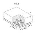
- the semiconductor component presented in FIG. 1conventionally comprises a silicon wafer or chip 1, connected by wires link conductors 2, such as 2A, 2B, 2C, 2D, 2E to a network of metallic connection areas 3, such as 3A, 3B, 3C, 3D, 3E, which ensure the electrical connection of the circuits contained in the chip 1 with the outside of the component.
- a metal zone 4preferably coplanar with the connection zones 3 ensures the thermal connection of the patch 1 with the outside, for the evacuation of the calories generated by the operation.
- the patch, the connecting wires 2 and the connection zones 3are covered by a hardened resin 5 which provides electrical isolation and immobilization of the wires 2 and of the patch 1 between them and with respect to the connection zones 3 and 4 .
- connection zones 3 and 4intended to ensure their connection with non-illustrated connections serving non-illustrated external circuits, is welded to a conductive layer of low-melting alloy 6 covering a metallic substrate 7, said to be temporary , ensuring protection of the connection areas against deterioration and pollution before use of the component.
- the fusion of the alloy layer 6allows the withdrawal of the temporary substrate 7 which ensures the updating of the faces of the connection zones 3 and 4 used to connect the component with the outside.
- the encapsulation processis as follows. First, a thin conductive layer of low-melting point alloy 6 is produced on a normally conductive metal substrate 7.
- the substrateis composed for example of a conventional sheet metal and the alloy is for example of the tin-lead type allowing the welding and the tinning of the metals on which it is deposited.
- This depositing of alloycan be carried out by any suitable means, it is for example an electrolytic deposit of sufficient thickness to avoid the creation of ternary alloy of the tin-lead-copper type at relatively high melting temperature during the next step in forming the metal connection zones, for example a minimum thickness of the order of ten to thirty microns will be chosen.
- This first stepis not necessarily directly followed by the following steps insofar as it is possible to use plates or a metallic tape previously covered alloy with low melting point.
- the metal connection zones 3 and 4are produced in the form of a network which is arranged on the alloy layer 6 (FIG. 2).
- a first of theseconsists in using a precut metal sheet comprising the different connection zones 3 and 4 connected together by temporary connections not shown here which are removed after welding from the connection zones on the alloy layer.
- This solutionmakes it possible to significantly reduce the surface occupied by the connection zones of a wafer insofar as one can benefit from temporary connections when welding connection zones 3 and 4 on the alloy layer 6 to resist mechanical stresses which will then be supported by the hardened resin including the component obtained.
- the metal intended to form the metallic connection networkis deposited on the alloy layer 6 carried by the substrate 7.
- the networkis for example obtained by selective deposition, through a mask, of a metal such as copper or nickel or by selective removal of an overall uniform metallic deposit according in particular to photolithography techniques.
- the result obtainedis a metal network preferably arranged in a regular repeating pattern such as those presented in Figures 4 and 5, allowing the simultaneous and / or continuous production of components encapsulated according to the invention.
- the thickness and dimensions of the studs that constitute the different connection zones 3 and 4 as well as their spacingare chosen as a function of the usual electrical stresses, without the mechanical stresses introduced by the use of networks made from sheets precut since the pads thus obtained are subject to the temporary substrate 7 by the alloy layer which served as a basis for their production.
- connection network of minimum size for each patch 1 on the temporary substrate 7 covered with alloyIt is therefore possible to use the usual techniques in microelectronics to produce a connection network of minimum size for each patch 1 on the temporary substrate 7 covered with alloy.
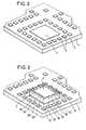
- the pads 1are then placed on their respective areas 4 and their electrical connection to the corresponding connection areas 3 by connecting wires 2 such as the pad 1 on the area 4 and with the areas 3A, 3B ... via the connecting wires 2A, 2B ... as shown in FIG. 3.
- the means usedare those usually used for positioning and connecting pads on an insulating substrate provided with connection zones.
- each componentis carried out by means of a hardenable resin 5 cast or molded covering the patch 1, the connecting wires 2 and the connection zones 3 is also produced in a conventional manner.
- the hardening of this resin by cooling or polymerizationmakes it possible to subject the various elements 1, 2, 3 and 4 of each component to each other.
- the melting of the alloy layer 6 by simple heating at a relatively low temperaturemakes it possible to eliminate the temporary metallic substrate 7 which has made it possible to produce a small metallic connection network.
- the removal of the temporary substrate 7which can be carried out either at the end of the component production process, or subsequently during the implementation of the components makes it possible to update the faces of the connection zones 3 and 4 which are intended for the electrical and / or thermal connection with the outside.
- the withdrawal of the temporary substrate 7 just before implementationhas the advantage of providing protection against damage by shock or friction and against pollution of the areas on which contacts with the outside will be established.
- the fusion of the alloy layeralso leaves a tinning film on the bare faces of the connection zones, which makes it possible to avoid a tinning operation normally necessary for welding the connections coming from the outside not figured here.
- the metallic connection networkhas a regular repeating pattern, preferably in a matrix, in which diffusion pads thermal 4 whose dimensions correspond to those of the pellets 1 are respectively surrounded by satellite connection zones 3.
- Each componentis separated from the others after coating in the resin and hardening of the latter, by sawing or cutting, either before or after removal of the temporary substrate ..
- FIG. 4presents a view of such a unitary component whose connection areas 3 and 4 have been exposed.
- the metallic connection networkis produced according to a regular pattern composed of identical studs arranged in a matrix, as shown in FIG. 5.
- the thermal diffusion zone arranged under the patchis then composed of a plurality of pads 3 shown in gray which are identical to the electrical connection pad 3 which surrounds them.
Landscapes
- Engineering & Computer Science (AREA)
- Computer Hardware Design (AREA)
- Microelectronics & Electronic Packaging (AREA)
- Power Engineering (AREA)
- Physics & Mathematics (AREA)
- Condensed Matter Physics & Semiconductors (AREA)
- General Physics & Mathematics (AREA)
- Manufacturing & Machinery (AREA)
- Wire Bonding (AREA)
- Structures Or Materials For Encapsulating Or Coating Semiconductor Devices Or Solid State Devices (AREA)
Abstract
Translated fromFrenchDescription
Translated fromFrenchLa présente invention a pour objet un procédé d'encapsulation de composants semi-conducteurs, notamment de composants de grande complexité et les composants encapsulés obtenus.The subject of the present invention is a method of encapsulating semiconductor components, in particular very complex components and the encapsulated components obtained.
L'encapsulation de composants semi-conducteurs de grande complexité est un élément important de la fabrication des circuits intégrés dans la mesure où les techniques utilisées sont souvent coûteuses, notamment si la production envisagée ne porte pas sur des séries suffisantes. Ceci est par exemple le cas de la technique de report de pastilles sur support-film dite TAB.The encapsulation of highly complex semiconductor components is an important element in the manufacture of integrated circuits since the techniques used are often expensive, especially if the production envisaged does not relate to sufficient series. This is for example the case of the technique of transferring pellets onto film support known as TAB.
Le principal problème posé est la réalisation des connexions permettant de relier les circuits intégrés avec l'extérieur, dans la mesure où l'on recherche à augmenter le nombre de connexions possibles en réduisant au maximum la taille du composant unitaire fabriqué. Or ce sont les nécessaires connexions avec l'extérieur qui exigent le plus de place, car on ne sait pas les réduire aux dimensions de celles qui sont mises en oeuvre à l'intérieur des circuits intégrés qu'elles desservent.The main problem posed is the creation of connections making it possible to connect integrated circuits with the outside, insofar as it is sought to increase the number of possible connections by reducing as much as possible the size of the unitary component manufactured. However, these are the necessary connections with the outside which require the most space, because we do not know how to reduce them to the dimensions of those which are implemented inside the integrated circuits which they serve.
En effet, si l'on reporte les pastilles par soudage sur un réseau métallique de connexion réalisé à partir d'une feuille métallique, les contraintes mécaniques de tenue du réseau avant soudage limitent la réduction des dimensions des pattes de connexion.In fact, if the pellets are transferred by welding onto a metallic connection network produced from a metal sheet, the mechanical constraints of the network holding before welding limit the reduction in the dimensions of the connection tabs.
Si par contre il est possible de réaliser un réseau de connexion de très petites dimensions sur un substrat par différentes techniques usuelles en microélectronique, telles que dépôt sélectif à travers un masque, ou photolithographie additive ou éventuellement soustractive si le substrat a été préalablement revêtu d'une couche métallique, on ne sait pas séparer le réseau de connexion du substrat isolant qui le porte et l'on ne peut donc utiliser le réseau de connexion ainsi formé sauf à placer les connexions du même côté que la pastille, ce qui n'est pas le but recherché.If, on the other hand, it is possible to produce a very small connection network on a substrate by various usual techniques in microelectronics, such as selective deposition through a mask, or additive or possibly subtractive photolithography if the substrate has been previously coated with a metallic layer, we do not know how to separate the connection network from the insulating substrate that carries it and we cannot therefore use the connection network thus formed unless the connections are placed on the same side as the patch, which is not not the goal.
La présente invention a donc pour objet un procédé d'encapsu- lation de composants semi-conducteurs et notamment de composants de grande complexité permettant la production de composants encapsulés ayant un réseau de connexion de très petites dimensions.The present invention therefore relates to a process for encapsulating semiconductor components and in particular components of high complexity allowing the production of encapsulated components having a very small connection network.
Selon une caractéristique de l'invention les connexions destinées à relier chaque composant avec l'extérieur sont réalisées sous forme d'un réseau métallique disposé sur une couche conductrice d'alliage à bas point de fusion qui recouvre un substrat métallique temporaire, après mise en place et, raccordement de chaque composant puis immobilisation au moyen d'une résine durcissable, le retrait du substrat temporaire par fusion de la couche d'alliage met à jour les faces des zones des connexions qui sont destinées à la mise en liaison électrique et/ou thermique des composants avec l'extérieur.According to a characteristic of the invention, the connections intended to connect each component with the outside are made in the form of a metal network disposed on a conductive layer of low-melting alloy which covers a temporary metallic substrate, after setting in place. place and, connection of each component then immobilization by means of a hardenable resin, the removal of the temporary substrate by fusion of the alloy layer updates the faces of the areas of the connections which are intended for the electrical connection and / or thermal components with the outside.
De plus les composants encapsulés, selon le procédé objet de l'invention, qui comportent chacun au moins une pastille immobilisée dans une résine durcie avec ses fils de liaison à des zones de connexion métalliques et coplanaires destinées à assurer sa mise en liaison avec l'extérieur, comportent également un substrat métallique temporaire de protection lié aux zones métalliques de connexion par une couche d'alliage à bas point de fusion dont la fusion permet de retirer le substrat temporaire et de mettre à jour les faces des zones de connexion qui sont destinées à la mise en liaison électrique et/ou thermique avec l'extérieur.
- La figure 1 présente une vue en arraché partiel d'un composant réalisé selon l'invention.
- La figure 2 présente une vue d'un ensemble substrat temporaire, couche d'alliage, couche métallique correspondant à une étape intermédiaire du procédé d'encapsulation de composants selon l'invention.
- La figure 3 présente une vue d'un ensemble selon la figure 2 d'une pastille montée et raccordée correspondant à une étape ultérieure du procédé d'encapsulation selon l'invention.
- La figure 4 présente une vue de dessous d'un composant encapsulé selon l'invention.
- La figure 5 présente une vue de dessous d'un composant encapsulé selon une variante de l'invention.
- Figure 1 shows a partial cutaway view of a component produced according to the invention.
- FIG. 2 shows a view of a temporary substrate, alloy layer and metal layer assembly corresponding to an intermediate step in the process for encapsulating components according to the invention.
- FIG. 3 shows a view of an assembly according to FIG. 2 of a wafer mounted and connected corresponding to a later stage of the encapsulation method according to the invention.
- Figure 4 shows a bottom view of an encapsulated component according to the invention.
- Figure 5 shows a bottom view of an encapsulated component according to a variant of the invention.
Le composant semi-conducteur présenté à la figure 1 comporte classiquement une pastille ou puce de silicium 1, reliée par des fils conducteurs de liaisons 2, tels 2A, 2B, 2C, 2D, 2E à un réseau de zones métalliques de connexion 3, tels 3A, 3B, 3C, 3D, 3E, qui assurent la mise en liaison électrique des circuits contenus dans la pastille 1 avec l'extérieur du composant. Dans l'exemple présenté une zone métallique 4 préférablement coplanaire avec les zones de connexion 3 assure la mise en liaison thermique de la pastille 1 avec l'extérieur, pour l'évacuation des calories engendrées par le fonctionnement.The semiconductor component presented in FIG. 1 conventionally comprises a silicon wafer or chip 1, connected by wires link conductors 2, such as 2A, 2B, 2C, 2D, 2E to a network of metallic connection areas 3, such as 3A, 3B, 3C, 3D, 3E, which ensure the electrical connection of the circuits contained in the chip 1 with the outside of the component. In the example presented a
La pastille, les fils de liaison 2 et les zones de connexion 3 sont recouvertes par une résine 5 durcie qui assure un isolement électrique et l'immobilisation des fils 2 et de la pastille 1 entre eux et par rapport aux zones de connexion 3 et 4.The patch, the connecting wires 2 and the connection zones 3 are covered by a hardened
La face de ces zones de connexion 3 et 4 destinée à assurer leur connexion avec des liaisons non figurées desservant des circuits extérieurs non figurés, est soudée à une couche conductrice d'alliage à bas point de fusion 6 recouvrant un substrat métallique 7, dit temporaire, assurant une protection des zones de connexion contre les détériorations et les pollutions avant utilisation du composant. La fusion de la couche d'alliage 6 permet le retrait du substrat temporaire 7 ce qui assure la mise à jour des faces des zones de connexion 3 et 4 servant à raccorder le composant avec l'extérieur.The face of these
Selon l'invention le procédé d'encapsulation est le suivant. En premier lieu on réalise une mince couche conductrice d'alliage à bas point de fusion 6 sur un substrat métallique 7 normalement conducteur.According to the invention, the encapsulation process is as follows. First, a thin conductive layer of low-
Le substrat est composé par exemple d'une classique tôle et l'alliage est par exemple du type étain-plomb permettant le soudage et l'étamage des métaux sur lequel on le dépose. Ce dépôt d'alliage peut être effectué par tout moyen approprié, c'est par exemple un dépôt électrolytique d'épaisseur suffisante pour éviter la création d'alliage ternaire du type étain-plomb-cuivre à température de fusion relativement élevée lors de l'étape suivante de constitution des zones de connexion métallique, on choisira par exemple une épaisseur minimale de l'ordre de dix à trente microns.The substrate is composed for example of a conventional sheet metal and the alloy is for example of the tin-lead type allowing the welding and the tinning of the metals on which it is deposited. This depositing of alloy can be carried out by any suitable means, it is for example an electrolytic deposit of sufficient thickness to avoid the creation of ternary alloy of the tin-lead-copper type at relatively high melting temperature during the next step in forming the metal connection zones, for example a minimum thickness of the order of ten to thirty microns will be chosen.
Cette première étape n'est pas nécessairement directement suivie par les étapes suivantes dans la mesure où il est envisageable d'utiliser des plaques ou un ruban métallique préalablement recouverts d'alliage à bas point de fusion.This first step is not necessarily directly followed by the following steps insofar as it is possible to use plates or a metallic tape previously covered alloy with low melting point.
En second lieu on réalise les zones de connexion métallique 3 et 4 sous forme d'un réseau qui est disposé sur la couche d'alliage 6 (figure 2).Secondly, the
Plusieurs techniques sont possibles, une première d'entre elles consiste à utiliser une feuille métallique prédécoupée comportant les différentes zones de connexion 3 et 4 reliées entre elles par des liaisons temporaires non figurées ici que l'on retire après soudage des zones de connexion sur la couche d'alliage. Cette solution permet de réduire notablement la surface occupée par les zones de connexion d'une pastille dans la mesure où l'on peut bénéficier des liaisons temporaires lors du soudage des zones de connexion 3 et 4 sur la couche d'alliage 6 pour résister aux contraintes mécaniques qui seront ensuite supportées par la résine durcie englobant la composant obtenu.Several techniques are possible, a first of these consists in using a precut metal sheet comprising the
Selon une variante de l'invention le métal destiné à former le réseau métallique de connexion est déposé sur la couche d'alliage 6 portée par le substrat 7. Le réseau est par exemple obtenu par dépôt sélectif, à travers un masque, d'un métal tel que du cuivre ou du nickel ou par enlèvement sélectif d'un dépôt métallique uniforme global selon notamment les techniques de photolithographie. Le résultat obtenu est un réseau métallique disposé préférablement selon un motif répétitif régulier tel que ceux présentés aux figures 4 et 5, permettant la réalisation simultanée et/ou en continu de composants encapsulés selon l'invention. L'épaisseur et les dimensions des plots que constituent les différentes zones de connexion 3 et 4 ainsi que leur écartement sont choisis en fonction des contraintes électriques usuelles, sans qu'interviennent les contraintes mécaniques introduites par l'emploi de réseaux réalisée à partir de feuilles prédécoupées puisque les plots ainsi obtenus sont assujettis au substrat temporaire 7 par la couche d'alliage qui a servi de base à leur réalisation.According to a variant of the invention, the metal intended to form the metallic connection network is deposited on the
Il est donc possible d'utiliser les techniques usuelles en microélectronique pour réaliser un réseau de connexion de taille minimle pour chaque pastille 1 sur le substrat temporaire 7 recouvert d'alliage.It is therefore possible to use the usual techniques in microelectronics to produce a connection network of minimum size for each patch 1 on the
On effectue ensuite la mise en place des pastilles 1 sur leurs zones 4 respectives et leur raccordement électrique aux zones de connexion 3 correspondantes par des fils de liaison 2 telle la pastille 1 sur la zone 4 et avec les zones 3A, 3B... via les fils de liaisons 2A, 2B... ainsi que le montre la figure 3. Les moyens utilisés sont ceux habituellement mis en oeuvre pour le positionnement et le raccordement de pastilles sur un substrat isolant doté de zones de connexion.The pads 1 are then placed on their
L'enrobage de chaque composant s'effectue au moyen d'une résine durcissable 5 coulée ou moulée recouvrant la pastille 1, les fils de liaison 2 et-les zones de connexion 3 est également réalisé de manière classique. Le durcissement de cette résine par refroidissement ou polymérisation permet d'assujettir les uns aux autres les différents éléments 1, 2, 3 et 4 de chaque composant.The coating of each component is carried out by means of a
Après durcissement de la résine 5 la fusion de la couche d'alliage 6 par simple chauffage à relativement basse température permet d'éliminer le substrat métallique temporaire 7 qui a permis la réalisation d'un réseau métallique de connexion de faibles dimensions.After the
Le retrait du substrat temporaire 7 qui peut s'effectuer soit en fin de procédé de production des composants, soit ultérieurement lors de la mise en oeuvre des composants permet de mettre à jour les faces des zones de connexion 3 et 4 qui sont destinées à la mise en liaison électrique et/ou thermique avec l'extérieur.The removal of the
Le retrait du substrat temporaire 7 juste avant mise en oeuvre présente l'avantage d'assurer la protection contre les détériorations par choc ou frottement et contre les pollutions des zones sur lesquelles les contacts avec l'extérieur seront établis.The withdrawal of the
la fusion de la couche d'alliage laisse de plus subsister un film d'étamage sur les faces à nu des zones de connexion, ce qui permet d'éviter une opération d'étamage normalement nécessaire au soudage des liaisons venant de l'extérieur non figurés ici.the fusion of the alloy layer also leaves a tinning film on the bare faces of the connection zones, which makes it possible to avoid a tinning operation normally necessary for welding the connections coming from the outside not figured here.
Ainsi qu'amorcé sur les dessins des figures 2 et 3 généralement on réalise bien entendu simultanément une pluralité de composants et le réseau métallique de connexion présente un motif répétitif régulier préférablement matriciel dans lequel des plots de diffusion thermique 4 dont les dimensions correspondent à celles des pastilles 1 sont respectivement entourés par des zones satellites de connexion 3. Chaque composant est séparé des autres après enrobage dans la résine et durcissement de cette dernière, par sciage ou sectionnement, soit avant soit après retrait du substrat temporaire..As started in the drawings of FIGS. 2 and 3, a plurality of components is of course produced simultaneously, of course, and the metallic connection network has a regular repeating pattern, preferably in a matrix, in which diffusion pads thermal 4 whose dimensions correspond to those of the pellets 1 are respectively surrounded by satellite connection zones 3. Each component is separated from the others after coating in the resin and hardening of the latter, by sawing or cutting, either before or after removal of the temporary substrate ..
La figure 4 présente une vue d'un tel composant unitaire dont les zones de connexion 3 et 4 ont été mise à nu.FIG. 4 presents a view of such a unitary component whose
Selon une variante de l'invention, on réalise le réseau métallique de connexion selon un motif régulier composé de plots identiques disposés matriciellement, ainsi que présenté à la figure 5. La zone de diffusion thermique disposée sous la pastille est alors composée d'une pluralité de plots 3 représentés en grisé qui sont identiques au plot de connexion électrique 3 qui les entourent.According to a variant of the invention, the metallic connection network is produced according to a regular pattern composed of identical studs arranged in a matrix, as shown in FIG. 5. The thermal diffusion zone arranged under the patch is then composed of a plurality of pads 3 shown in gray which are identical to the electrical connection pad 3 which surrounds them.
Ceci permet d'utiliser le même motif pour différents composants, ce qui présente un intérêt certain s'il est nécessaire de réaliser des petites séries de composants dont les pastilles sont différentes.This makes it possible to use the same pattern for different components, which is of certain interest if it is necessary to produce small series of components whose pellets are different.
Claims (8)
Translated fromFrenchApplications Claiming Priority (2)
| Application Number | Priority Date | Filing Date | Title |
|---|---|---|---|
| FR8205624 | 1982-04-01 | ||
| FR8205624AFR2524707B1 (en) | 1982-04-01 | 1982-04-01 | METHOD OF ENCAPSULATION OF SEMICONDUCTOR COMPONENTS, AND ENCAPSULATED COMPONENTS OBTAINED |
Publications (2)
| Publication Number | Publication Date |
|---|---|
| EP0091072A1true EP0091072A1 (en) | 1983-10-12 |
| EP0091072B1 EP0091072B1 (en) | 1987-01-21 |
Family
ID=9272637
Family Applications (1)
| Application Number | Title | Priority Date | Filing Date |
|---|---|---|---|
| EP83103114AExpiredEP0091072B1 (en) | 1982-04-01 | 1983-03-29 | Process for encapsulating semi-conductor components and encapsulated components so obtained |
Country Status (5)
| Country | Link |
|---|---|
| US (1) | US4530152A (en) |
| EP (1) | EP0091072B1 (en) |
| JP (1) | JPS58182853A (en) |
| DE (1) | DE3369428D1 (en) |
| FR (1) | FR2524707B1 (en) |
Cited By (5)
| Publication number | Priority date | Publication date | Assignee | Title |
|---|---|---|---|---|
| FR2561040A1 (en)* | 1984-03-09 | 1985-09-13 | Lohja Ab Oy | METHOD FOR ENCAPSULATING ELECTRONIC COMPONENTS MOUNTED ON A CARRIER BELT |
| EP0472451A1 (en)* | 1990-08-21 | 1992-02-26 | Thomson-Csf | Hybrid integrated circuit interconnection structure and method of fabrication |
| EP0751561A4 (en)* | 1994-03-18 | 1997-05-07 | Hitachi Chemical Co Ltd | Semiconductor package manufacturing method and semiconductor package |
| WO1997044822A1 (en)* | 1995-05-11 | 1997-11-27 | National Semiconductor Corporation | Ultra thin ball grid array package using a flex tape or printed wiring board substrate and method |
| WO2000022668A1 (en)* | 1998-10-09 | 2000-04-20 | Tyco Electronics Logistics Ag | Electronic module, especially a multichip module, with multi-layer metallization and corresponding production method |
Families Citing this family (212)
| Publication number | Priority date | Publication date | Assignee | Title |
|---|---|---|---|---|
| JPS6149432A (en)* | 1984-08-18 | 1986-03-11 | Matsushita Electric Ind Co Ltd | Manufacturing method of semiconductor device |
| IT1202657B (en)* | 1987-03-09 | 1989-02-09 | Sgs Microelettronica Spa | MANUFACTURING PROCEDURE OF A SEMICONDUCTOR MODULAR POWER DEVICE AND DEVICE WITH IT OBTAINED |
| US5032543A (en)* | 1988-06-17 | 1991-07-16 | Massachusetts Institute Of Technology | Coplanar packaging techniques for multichip circuits |
| US5008997A (en)* | 1988-09-16 | 1991-04-23 | National Semiconductor | Gold/tin eutectic bonding for tape automated bonding process |
| US5200362A (en)* | 1989-09-06 | 1993-04-06 | Motorola, Inc. | Method of attaching conductive traces to an encapsulated semiconductor die using a removable transfer film |
| US5293072A (en)* | 1990-06-25 | 1994-03-08 | Fujitsu Limited | Semiconductor device having spherical terminals attached to the lead frame embedded within the package body |
| EP0509065A1 (en)* | 1990-08-01 | 1992-10-21 | Staktek Corporation | Ultra high density integrated circuit packages, method and apparatus |
| US5475920A (en)* | 1990-08-01 | 1995-12-19 | Burns; Carmen D. | Method of assembling ultra high density integrated circuit packages |
| US5446620A (en)* | 1990-08-01 | 1995-08-29 | Staktek Corporation | Ultra high density integrated circuit packages |
| US5367766A (en)* | 1990-08-01 | 1994-11-29 | Staktek Corporation | Ultra high density integrated circuit packages method |
| US5377077A (en)* | 1990-08-01 | 1994-12-27 | Staktek Corporation | Ultra high density integrated circuit packages method and apparatus |
| DE4141775A1 (en)* | 1991-12-18 | 1993-06-24 | Manfred Band | Electronic circuits mfr. - using temporary substrate for assembly and fixing with cast epoxy] resin |
| US5273940A (en)* | 1992-06-15 | 1993-12-28 | Motorola, Inc. | Multiple chip package with thinned semiconductor chips |
| US5344795A (en)* | 1992-09-22 | 1994-09-06 | Microelectronics And Computer Technology Corporation | Method for encapsulating an integrated circuit using a removable heatsink support block |
| US5497032A (en)* | 1993-03-17 | 1996-03-05 | Fujitsu Limited | Semiconductor device and lead frame therefore |
| US5369056A (en)* | 1993-03-29 | 1994-11-29 | Staktek Corporation | Warp-resistent ultra-thin integrated circuit package fabrication method |
| US5644161A (en)* | 1993-03-29 | 1997-07-01 | Staktek Corporation | Ultra-high density warp-resistant memory module |
| US5801437A (en)* | 1993-03-29 | 1998-09-01 | Staktek Corporation | Three-dimensional warp-resistant integrated circuit module method and apparatus |
| GB9401770D0 (en)* | 1994-01-31 | 1994-03-23 | Philips Electronics Uk Ltd | Manufacture of electronic devices comprising thin-film circuits |
| US6465743B1 (en)* | 1994-12-05 | 2002-10-15 | Motorola, Inc. | Multi-strand substrate for ball-grid array assemblies and method |
| US5832600A (en)* | 1995-06-06 | 1998-11-10 | Seiko Epson Corporation | Method of mounting electronic parts |
| US6025642A (en)* | 1995-08-17 | 2000-02-15 | Staktek Corporation | Ultra high density integrated circuit packages |
| JP3207738B2 (en)* | 1996-01-15 | 2001-09-10 | 株式会社東芝 | Resin-sealed semiconductor device and method of manufacturing the same |
| US6821821B2 (en) | 1996-04-18 | 2004-11-23 | Tessera, Inc. | Methods for manufacturing resistors using a sacrificial layer |
| US6001671A (en)* | 1996-04-18 | 1999-12-14 | Tessera, Inc. | Methods for manufacturing a semiconductor package having a sacrificial layer |
| KR100418743B1 (en)* | 1996-07-12 | 2004-02-18 | 후지쯔 가부시끼가이샤 | Method for manufacturing semiconductor device and semiconductor device |
| US6881611B1 (en)* | 1996-07-12 | 2005-04-19 | Fujitsu Limited | Method and mold for manufacturing semiconductor device, semiconductor device and method for mounting the device |
| US5776798A (en)* | 1996-09-04 | 1998-07-07 | Motorola, Inc. | Semiconductor package and method thereof |
| US5981314A (en)* | 1996-10-31 | 1999-11-09 | Amkor Technology, Inc. | Near chip size integrated circuit package |
| US6962829B2 (en)* | 1996-10-31 | 2005-11-08 | Amkor Technology, Inc. | Method of making near chip size integrated circuit package |
| US6150193A (en)* | 1996-10-31 | 2000-11-21 | Amkor Technology, Inc. | RF shielded device |
| US6583444B2 (en)* | 1997-02-18 | 2003-06-24 | Tessera, Inc. | Semiconductor packages having light-sensitive chips |
| US5945732A (en)* | 1997-03-12 | 1999-08-31 | Staktek Corporation | Apparatus and method of manufacturing a warp resistant thermally conductive integrated circuit package |
| US6034429A (en)* | 1997-04-18 | 2000-03-07 | Amkor Technology, Inc. | Integrated circuit package |
| US6117705A (en)* | 1997-04-18 | 2000-09-12 | Amkor Technology, Inc. | Method of making integrated circuit package having adhesive bead supporting planar lid above planar substrate |
| US5962810A (en)* | 1997-09-09 | 1999-10-05 | Amkor Technology, Inc. | Integrated circuit package employing a transparent encapsulant |
| US7247526B1 (en) | 1998-06-10 | 2007-07-24 | Asat Ltd. | Process for fabricating an integrated circuit package |
| US6635957B2 (en) | 1998-06-10 | 2003-10-21 | Asat Ltd. | Leadless plastic chip carrier with etch back pad singulation and die attach pad array |
| US7270867B1 (en) | 1998-06-10 | 2007-09-18 | Asat Ltd. | Leadless plastic chip carrier |
| US7049177B1 (en) | 2004-01-28 | 2006-05-23 | Asat Ltd. | Leadless plastic chip carrier with standoff contacts and die attach pad |
| US8330270B1 (en) | 1998-06-10 | 2012-12-11 | Utac Hong Kong Limited | Integrated circuit package having a plurality of spaced apart pad portions |
| US7226811B1 (en) | 1998-06-10 | 2007-06-05 | Asat Ltd. | Process for fabricating a leadless plastic chip carrier |
| US6585905B1 (en)* | 1998-06-10 | 2003-07-01 | Asat Ltd. | Leadless plastic chip carrier with partial etch die attach pad |
| US6294100B1 (en) | 1998-06-10 | 2001-09-25 | Asat Ltd | Exposed die leadless plastic chip carrier |
| US7271032B1 (en) | 1998-06-10 | 2007-09-18 | Asat Ltd. | Leadless plastic chip carrier with etch back pad singulation |
| US6872661B1 (en) | 1998-06-10 | 2005-03-29 | Asat Ltd. | Leadless plastic chip carrier with etch back pad singulation and die attach pad array |
| US6989294B1 (en) | 1998-06-10 | 2006-01-24 | Asat, Ltd. | Leadless plastic chip carrier with etch back pad singulation |
| US6229200B1 (en) | 1998-06-10 | 2001-05-08 | Asat Limited | Saw-singulated leadless plastic chip carrier |
| US6498099B1 (en)* | 1998-06-10 | 2002-12-24 | Asat Ltd. | Leadless plastic chip carrier with etch back pad singulation |
| US6933594B2 (en)* | 1998-06-10 | 2005-08-23 | Asat Ltd. | Leadless plastic chip carrier with etch back pad singulation |
| US7332375B1 (en) | 1998-06-24 | 2008-02-19 | Amkor Technology, Inc. | Method of making an integrated circuit package |
| US7030474B1 (en) | 1998-06-24 | 2006-04-18 | Amkor Technology, Inc. | Plastic integrated circuit package and method and leadframe for making the package |
| US7005326B1 (en) | 1998-06-24 | 2006-02-28 | Amkor Technology, Inc. | Method of making an integrated circuit package |
| US6893900B1 (en) | 1998-06-24 | 2005-05-17 | Amkor Technology, Inc. | Method of making an integrated circuit package |
| US7071541B1 (en) | 1998-06-24 | 2006-07-04 | Amkor Technology, Inc. | Plastic integrated circuit package and method and leadframe for making the package |
| US6143981A (en) | 1998-06-24 | 2000-11-07 | Amkor Technology, Inc. | Plastic integrated circuit package and method and leadframe for making the package |
| US7112474B1 (en) | 1998-06-24 | 2006-09-26 | Amkor Technology, Inc. | Method of making an integrated circuit package |
| US6092281A (en) | 1998-08-28 | 2000-07-25 | Amkor Technology, Inc. | Electromagnetic interference shield driver and method |
| US6281568B1 (en) | 1998-10-21 | 2001-08-28 | Amkor Technology, Inc. | Plastic integrated circuit device package and leadframe having partially undercut leads and die pad |
| US6448633B1 (en) | 1998-11-20 | 2002-09-10 | Amkor Technology, Inc. | Semiconductor package and method of making using leadframe having lead locks to secure leads to encapsulant |
| JP3575001B2 (en)* | 1999-05-07 | 2004-10-06 | アムコー テクノロジー コリア インコーポレーティド | Semiconductor package and manufacturing method thereof |
| USRE40112E1 (en) | 1999-05-20 | 2008-02-26 | Amkor Technology, Inc. | Semiconductor package and method for fabricating the same |
| JP3398721B2 (en)* | 1999-05-20 | 2003-04-21 | アムコー テクノロジー コリア インコーポレーティド | Semiconductor package and manufacturing method thereof |
| JP3416737B2 (en) | 1999-05-20 | 2003-06-16 | アムコー テクノロジー コリア インコーポレーティド | Semiconductor package manufacturing method |
| JP3314304B2 (en) | 1999-06-07 | 2002-08-12 | アムコー テクノロジー コリア インコーポレーティド | Circuit board for semiconductor package |
| KR200309906Y1 (en) | 1999-06-30 | 2003-04-14 | 앰코 테크놀로지 코리아 주식회사 | lead frame for fabricating semiconductor package |
| US6247229B1 (en) | 1999-08-25 | 2001-06-19 | Ankor Technology, Inc. | Method of forming an integrated circuit device package using a plastic tape as a base |
| US20020100165A1 (en) | 2000-02-14 | 2002-08-01 | Amkor Technology, Inc. | Method of forming an integrated circuit device package using a temporary substrate |
| US6448635B1 (en) | 1999-08-30 | 2002-09-10 | Amkor Technology, Inc. | Surface acoustical wave flip chip |
| US20040038451A1 (en)* | 1999-10-06 | 2004-02-26 | Hawks Douglas A. | Method suitable for forming a microelectronic device package |
| KR100403142B1 (en)* | 1999-10-15 | 2003-10-30 | 앰코 테크놀로지 코리아 주식회사 | semiconductor package |
| KR20010037254A (en) | 1999-10-15 | 2001-05-07 | 마이클 디. 오브라이언 | Semiconductor package |
| KR100355796B1 (en) | 1999-10-15 | 2002-10-19 | 앰코 테크놀로지 코리아 주식회사 | structure of leadframe for semiconductor package and mold for molding the same |
| KR20010037247A (en) | 1999-10-15 | 2001-05-07 | 마이클 디. 오브라이언 | Semiconductor package |
| KR100526844B1 (en)* | 1999-10-15 | 2005-11-08 | 앰코 테크놀로지 코리아 주식회사 | semiconductor package and its manufacturing method |
| US6525406B1 (en) | 1999-10-15 | 2003-02-25 | Amkor Technology, Inc. | Semiconductor device having increased moisture path and increased solder joint strength |
| KR20010056618A (en) | 1999-12-16 | 2001-07-04 | 프랑크 제이. 마르쿠치 | Semiconductor package |
| KR100355795B1 (en)* | 1999-10-15 | 2002-10-19 | 앰코 테크놀로지 코리아 주식회사 | manufacturing method of semiconductor package |
| KR100379089B1 (en) | 1999-10-15 | 2003-04-08 | 앰코 테크놀로지 코리아 주식회사 | leadframe and semiconductor package using it |
| KR100355794B1 (en) | 1999-10-15 | 2002-10-19 | 앰코 테크놀로지 코리아 주식회사 | leadframe and semiconductor package using the same |
| KR20010037252A (en) | 1999-10-15 | 2001-05-07 | 마이클 디. 오브라이언 | Mold for manufacturing semiconductor package |
| KR100364978B1 (en) | 1999-10-15 | 2002-12-16 | 앰코 테크놀로지 코리아 주식회사 | Clamp and Heat Block for Wire Bonding in Semiconductor Package |
| US6580159B1 (en) | 1999-11-05 | 2003-06-17 | Amkor Technology, Inc. | Integrated circuit device packages and substrates for making the packages |
| US20070176287A1 (en)* | 1999-11-05 | 2007-08-02 | Crowley Sean T | Thin integrated circuit device packages for improved radio frequency performance |
| US6847103B1 (en) | 1999-11-09 | 2005-01-25 | Amkor Technology, Inc. | Semiconductor package with exposed die pad and body-locking leadframe |
| US6476478B1 (en) | 1999-11-12 | 2002-11-05 | Amkor Technology, Inc. | Cavity semiconductor package with exposed leads and die pad |
| US6639308B1 (en)* | 1999-12-16 | 2003-10-28 | Amkor Technology, Inc. | Near chip size semiconductor package |
| KR100421774B1 (en) | 1999-12-16 | 2004-03-10 | 앰코 테크놀로지 코리아 주식회사 | semiconductor package and its manufacturing method |
| KR100426494B1 (en) | 1999-12-20 | 2004-04-13 | 앰코 테크놀로지 코리아 주식회사 | Semiconductor package and its manufacturing method |
| KR20010058583A (en) | 1999-12-30 | 2001-07-06 | 마이클 디. 오브라이언 | Lead End Grid Array Semiconductor package |
| KR100559664B1 (en) | 2000-03-25 | 2006-03-10 | 앰코 테크놀로지 코리아 주식회사 | Semiconductor Package |
| KR100583494B1 (en)* | 2000-03-25 | 2006-05-24 | 앰코 테크놀로지 코리아 주식회사 | Semiconductor Package |
| US7042068B2 (en) | 2000-04-27 | 2006-05-09 | Amkor Technology, Inc. | Leadframe and semiconductor package made using the leadframe |
| US6624005B1 (en) | 2000-09-06 | 2003-09-23 | Amkor Technology, Inc. | Semiconductor memory cards and method of making same |
| NL1016334C2 (en)* | 2000-10-05 | 2002-04-08 | Boschman Tech Bv | A laser cutting method for a composite integrated circuit structure includes measuring the radiation emitted during cutting with a light-sensitive element and adjusting the power of the laser when a material transition is detected |
| NL1018403C1 (en)* | 2000-10-05 | 2002-04-08 | Boschman Tech Bv | Method for cutting a composite structure with one or more electronic components using a laser. |
| KR20020058209A (en) | 2000-12-29 | 2002-07-12 | 마이클 디. 오브라이언 | Semiconductor package |
| KR100731007B1 (en)* | 2001-01-15 | 2007-06-22 | 앰코 테크놀로지 코리아 주식회사 | Stacked Semiconductor Packages |
| KR100394030B1 (en)* | 2001-01-15 | 2003-08-06 | 앰코 테크놀로지 코리아 주식회사 | stack-type semiconductor package |
| WO2002061827A1 (en)* | 2001-01-31 | 2002-08-08 | Sony Corporation | Semiconductor device and its manufacturing method |
| US6486537B1 (en) | 2001-03-19 | 2002-11-26 | Amkor Technology, Inc. | Semiconductor package with warpage resistant substrate |
| US6605865B2 (en) | 2001-03-19 | 2003-08-12 | Amkor Technology, Inc. | Semiconductor package with optimized leadframe bonding strength |
| US6967395B1 (en) | 2001-03-20 | 2005-11-22 | Amkor Technology, Inc. | Mounting for a package containing a chip |
| US6545345B1 (en) | 2001-03-20 | 2003-04-08 | Amkor Technology, Inc. | Mounting for a package containing a chip |
| KR100369393B1 (en) | 2001-03-27 | 2003-02-05 | 앰코 테크놀로지 코리아 주식회사 | Lead frame and semiconductor package using it and its manufacturing method |
| KR100393448B1 (en) | 2001-03-27 | 2003-08-02 | 앰코 테크놀로지 코리아 주식회사 | Semiconductor package and method for manufacturing the same |
| US6597059B1 (en) | 2001-04-04 | 2003-07-22 | Amkor Technology, Inc. | Thermally enhanced chip scale lead on chip semiconductor package |
| US7045883B1 (en) | 2001-04-04 | 2006-05-16 | Amkor Technology, Inc. | Thermally enhanced chip scale lead on chip semiconductor package and method of making same |
| US7064009B1 (en) | 2001-04-04 | 2006-06-20 | Amkor Technology, Inc. | Thermally enhanced chip scale lead on chip semiconductor package and method of making same |
| US6756658B1 (en) | 2001-04-06 | 2004-06-29 | Amkor Technology, Inc. | Making two lead surface mounting high power microleadframe semiconductor packages |
| US6534338B1 (en) | 2001-06-29 | 2003-03-18 | Amkor Technology, Inc. | Method for molding semiconductor package having a ceramic substrate |
| US7485952B1 (en) | 2001-09-19 | 2009-02-03 | Amkor Technology, Inc. | Drop resistant bumpers for fully molded memory cards |
| US6900527B1 (en) | 2001-09-19 | 2005-05-31 | Amkor Technology, Inc. | Lead-frame method and assembly for interconnecting circuits within a circuit module |
| DE10148043A1 (en)* | 2001-09-28 | 2003-01-02 | Infineon Technologies Ag | Electronic component comprises a plastic housing having islands arranged on the lower side of the housing in a matrix |
| US6611047B2 (en) | 2001-10-12 | 2003-08-26 | Amkor Technology, Inc. | Semiconductor package with singulation crease |
| US6630726B1 (en) | 2001-11-07 | 2003-10-07 | Amkor Technology, Inc. | Power semiconductor package with strap |
| US6798046B1 (en) | 2002-01-22 | 2004-09-28 | Amkor Technology, Inc. | Semiconductor package including ring structure connected to leads with vertically downset inner ends |
| US6885086B1 (en) | 2002-03-05 | 2005-04-26 | Amkor Technology, Inc. | Reduced copper lead frame for saw-singulated chip package |
| US6608366B1 (en) | 2002-04-15 | 2003-08-19 | Harry J. Fogelson | Lead frame with plated end leads |
| US6627977B1 (en) | 2002-05-09 | 2003-09-30 | Amkor Technology, Inc. | Semiconductor package including isolated ring structure |
| US6841414B1 (en) | 2002-06-19 | 2005-01-11 | Amkor Technology, Inc. | Saw and etch singulation method for a chip package |
| US6867071B1 (en) | 2002-07-12 | 2005-03-15 | Amkor Technology, Inc. | Leadframe including corner leads and semiconductor package using same |
| US7732914B1 (en) | 2002-09-03 | 2010-06-08 | Mclellan Neil | Cavity-type integrated circuit package |
| US6818973B1 (en) | 2002-09-09 | 2004-11-16 | Amkor Technology, Inc. | Exposed lead QFP package fabricated through the use of a partial saw process |
| US6919620B1 (en) | 2002-09-17 | 2005-07-19 | Amkor Technology, Inc. | Compact flash memory card with clamshell leadframe |
| US7723210B2 (en) | 2002-11-08 | 2010-05-25 | Amkor Technology, Inc. | Direct-write wafer level chip scale package |
| US7190062B1 (en) | 2004-06-15 | 2007-03-13 | Amkor Technology, Inc. | Embedded leadframe semiconductor package |
| US7361533B1 (en) | 2002-11-08 | 2008-04-22 | Amkor Technology, Inc. | Stacked embedded leadframe |
| US6905914B1 (en) | 2002-11-08 | 2005-06-14 | Amkor Technology, Inc. | Wafer level package and fabrication method |
| US6798047B1 (en) | 2002-12-26 | 2004-09-28 | Amkor Technology, Inc. | Pre-molded leadframe |
| US6847099B1 (en) | 2003-02-05 | 2005-01-25 | Amkor Technology Inc. | Offset etched corner leads for semiconductor package |
| US6750545B1 (en) | 2003-02-28 | 2004-06-15 | Amkor Technology, Inc. | Semiconductor package capable of die stacking |
| US6794740B1 (en) | 2003-03-13 | 2004-09-21 | Amkor Technology, Inc. | Leadframe package for semiconductor devices |
| US7001799B1 (en) | 2003-03-13 | 2006-02-21 | Amkor Technology, Inc. | Method of making a leadframe for semiconductor devices |
| US7095103B1 (en) | 2003-05-01 | 2006-08-22 | Amkor Technology, Inc. | Leadframe based memory card |
| US7008825B1 (en) | 2003-05-27 | 2006-03-07 | Amkor Technology, Inc. | Leadframe strip having enhanced testability |
| US6897550B1 (en) | 2003-06-11 | 2005-05-24 | Amkor Technology, Inc. | Fully-molded leadframe stand-off feature |
| US7033517B1 (en) | 2003-09-15 | 2006-04-25 | Asat Ltd. | Method of fabricating a leadless plastic chip carrier |
| US7245007B1 (en) | 2003-09-18 | 2007-07-17 | Amkor Technology, Inc. | Exposed lead interposer leadframe package |
| US6921967B2 (en)* | 2003-09-24 | 2005-07-26 | Amkor Technology, Inc. | Reinforced die pad support structure |
| US7138707B1 (en) | 2003-10-21 | 2006-11-21 | Amkor Technology, Inc. | Semiconductor package including leads and conductive posts for providing increased functionality |
| US7144517B1 (en) | 2003-11-07 | 2006-12-05 | Amkor Technology, Inc. | Manufacturing method for leadframe and for semiconductor package using the leadframe |
| US7211879B1 (en) | 2003-11-12 | 2007-05-01 | Amkor Technology, Inc. | Semiconductor package with chamfered corners and method of manufacturing the same |
| US7009286B1 (en) | 2004-01-15 | 2006-03-07 | Asat Ltd. | Thin leadless plastic chip carrier |
| US7009296B1 (en) | 2004-01-15 | 2006-03-07 | Amkor Technology, Inc. | Semiconductor package with substrate coupled to a peripheral side surface of a semiconductor die |
| US7057268B1 (en) | 2004-01-27 | 2006-06-06 | Amkor Technology, Inc. | Cavity case with clip/plug for use on multi-media card |
| US7091594B1 (en) | 2004-01-28 | 2006-08-15 | Amkor Technology, Inc. | Leadframe type semiconductor package having reduced inductance and its manufacturing method |
| US20080003722A1 (en)* | 2004-04-15 | 2008-01-03 | Chun David D | Transfer mold solution for molded multi-media card |
| US7411289B1 (en) | 2004-06-14 | 2008-08-12 | Asat Ltd. | Integrated circuit package with partially exposed contact pads and process for fabricating the same |
| US7091581B1 (en) | 2004-06-14 | 2006-08-15 | Asat Limited | Integrated circuit package and process for fabricating the same |
| US7202554B1 (en) | 2004-08-19 | 2007-04-10 | Amkor Technology, Inc. | Semiconductor package and its manufacturing method |
| US7595225B1 (en) | 2004-10-05 | 2009-09-29 | Chun Ho Fan | Leadless plastic chip carrier with contact standoff |
| US7217991B1 (en) | 2004-10-22 | 2007-05-15 | Amkor Technology, Inc. | Fan-in leadframe semiconductor package |
| US7358119B2 (en)* | 2005-01-12 | 2008-04-15 | Asat Ltd. | Thin array plastic package without die attach pad and process for fabricating the same |
| US20060170081A1 (en)* | 2005-02-03 | 2006-08-03 | Gerber Mark A | Method and apparatus for packaging an electronic chip |
| US7348663B1 (en) | 2005-07-15 | 2008-03-25 | Asat Ltd. | Integrated circuit package and method for fabricating same |
| DE102005039165B4 (en)* | 2005-08-17 | 2010-12-02 | Infineon Technologies Ag | Wire and strip bonded semiconductor power device and method of making the same |
| US7410830B1 (en) | 2005-09-26 | 2008-08-12 | Asat Ltd | Leadless plastic chip carrier and method of fabricating same |
| US7507603B1 (en) | 2005-12-02 | 2009-03-24 | Amkor Technology, Inc. | Etch singulated semiconductor package |
| US7572681B1 (en) | 2005-12-08 | 2009-08-11 | Amkor Technology, Inc. | Embedded electronic component package |
| US7902660B1 (en) | 2006-05-24 | 2011-03-08 | Amkor Technology, Inc. | Substrate for semiconductor device and manufacturing method thereof |
| US7968998B1 (en) | 2006-06-21 | 2011-06-28 | Amkor Technology, Inc. | Side leaded, bottom exposed pad and bottom exposed lead fusion quad flat semiconductor package |
| US7687893B2 (en)* | 2006-12-27 | 2010-03-30 | Amkor Technology, Inc. | Semiconductor package having leadframe with exposed anchor pads |
| US7829990B1 (en) | 2007-01-18 | 2010-11-09 | Amkor Technology, Inc. | Stackable semiconductor package including laminate interposer |
| US9466545B1 (en) | 2007-02-21 | 2016-10-11 | Amkor Technology, Inc. | Semiconductor package in package |
| US7982297B1 (en) | 2007-03-06 | 2011-07-19 | Amkor Technology, Inc. | Stackable semiconductor package having partially exposed semiconductor die and method of fabricating the same |
| US7977774B2 (en) | 2007-07-10 | 2011-07-12 | Amkor Technology, Inc. | Fusion quad flat semiconductor package |
| US7687899B1 (en) | 2007-08-07 | 2010-03-30 | Amkor Technology, Inc. | Dual laminate package structure with embedded elements |
| US7777351B1 (en) | 2007-10-01 | 2010-08-17 | Amkor Technology, Inc. | Thin stacked interposer package |
| US8089159B1 (en) | 2007-10-03 | 2012-01-03 | Amkor Technology, Inc. | Semiconductor package with increased I/O density and method of making the same |
| US7847386B1 (en) | 2007-11-05 | 2010-12-07 | Amkor Technology, Inc. | Reduced size stacked semiconductor package and method of making the same |
| US7956453B1 (en) | 2008-01-16 | 2011-06-07 | Amkor Technology, Inc. | Semiconductor package with patterning layer and method of making same |
| US7723852B1 (en) | 2008-01-21 | 2010-05-25 | Amkor Technology, Inc. | Stacked semiconductor package and method of making same |
| US8067821B1 (en) | 2008-04-10 | 2011-11-29 | Amkor Technology, Inc. | Flat semiconductor package with half package molding |
| US7768135B1 (en) | 2008-04-17 | 2010-08-03 | Amkor Technology, Inc. | Semiconductor package with fast power-up cycle and method of making same |
| US7808084B1 (en) | 2008-05-06 | 2010-10-05 | Amkor Technology, Inc. | Semiconductor package with half-etched locking features |
| US8125064B1 (en) | 2008-07-28 | 2012-02-28 | Amkor Technology, Inc. | Increased I/O semiconductor package and method of making same |
| US8184453B1 (en) | 2008-07-31 | 2012-05-22 | Amkor Technology, Inc. | Increased capacity semiconductor package |
| US7847392B1 (en) | 2008-09-30 | 2010-12-07 | Amkor Technology, Inc. | Semiconductor device including leadframe with increased I/O |
| US7989933B1 (en) | 2008-10-06 | 2011-08-02 | Amkor Technology, Inc. | Increased I/O leadframe and semiconductor device including same |
| US8008758B1 (en) | 2008-10-27 | 2011-08-30 | Amkor Technology, Inc. | Semiconductor device with increased I/O leadframe |
| US8089145B1 (en) | 2008-11-17 | 2012-01-03 | Amkor Technology, Inc. | Semiconductor device including increased capacity leadframe |
| US8072050B1 (en) | 2008-11-18 | 2011-12-06 | Amkor Technology, Inc. | Semiconductor device with increased I/O leadframe including passive device |
| US7875963B1 (en) | 2008-11-21 | 2011-01-25 | Amkor Technology, Inc. | Semiconductor device including leadframe having power bars and increased I/O |
| US7982298B1 (en) | 2008-12-03 | 2011-07-19 | Amkor Technology, Inc. | Package in package semiconductor device |
| US8487420B1 (en) | 2008-12-08 | 2013-07-16 | Amkor Technology, Inc. | Package in package semiconductor device with film over wire |
| US8680656B1 (en) | 2009-01-05 | 2014-03-25 | Amkor Technology, Inc. | Leadframe structure for concentrated photovoltaic receiver package |
| US20170117214A1 (en) | 2009-01-05 | 2017-04-27 | Amkor Technology, Inc. | Semiconductor device with through-mold via |
| US8058715B1 (en) | 2009-01-09 | 2011-11-15 | Amkor Technology, Inc. | Package in package device for RF transceiver module |
| US8026589B1 (en) | 2009-02-23 | 2011-09-27 | Amkor Technology, Inc. | Reduced profile stackable semiconductor package |
| US7960818B1 (en) | 2009-03-04 | 2011-06-14 | Amkor Technology, Inc. | Conformal shield on punch QFN semiconductor package |
| US8575742B1 (en) | 2009-04-06 | 2013-11-05 | Amkor Technology, Inc. | Semiconductor device with increased I/O leadframe including power bars |
| US8796561B1 (en) | 2009-10-05 | 2014-08-05 | Amkor Technology, Inc. | Fan out build up substrate stackable package and method |
| US8937381B1 (en) | 2009-12-03 | 2015-01-20 | Amkor Technology, Inc. | Thin stackable package and method |
| US9691734B1 (en) | 2009-12-07 | 2017-06-27 | Amkor Technology, Inc. | Method of forming a plurality of electronic component packages |
| US8324511B1 (en) | 2010-04-06 | 2012-12-04 | Amkor Technology, Inc. | Through via nub reveal method and structure |
| US8294276B1 (en) | 2010-05-27 | 2012-10-23 | Amkor Technology, Inc. | Semiconductor device and fabricating method thereof |
| US8440554B1 (en) | 2010-08-02 | 2013-05-14 | Amkor Technology, Inc. | Through via connected backside embedded circuit features structure and method |
| US8487445B1 (en) | 2010-10-05 | 2013-07-16 | Amkor Technology, Inc. | Semiconductor device having through electrodes protruding from dielectric layer |
| US8791501B1 (en) | 2010-12-03 | 2014-07-29 | Amkor Technology, Inc. | Integrated passive device structure and method |
| US8674485B1 (en) | 2010-12-08 | 2014-03-18 | Amkor Technology, Inc. | Semiconductor device including leadframe with downsets |
| US8390130B1 (en) | 2011-01-06 | 2013-03-05 | Amkor Technology, Inc. | Through via recessed reveal structure and method |
| TWI557183B (en) | 2015-12-16 | 2016-11-11 | 財團法人工業技術研究院 | Oxane composition, and photovoltaic device comprising the same |
| US8648450B1 (en) | 2011-01-27 | 2014-02-11 | Amkor Technology, Inc. | Semiconductor device including leadframe with a combination of leads and lands |
| US8552548B1 (en) | 2011-11-29 | 2013-10-08 | Amkor Technology, Inc. | Conductive pad on protruding through electrode semiconductor device |
| US9704725B1 (en) | 2012-03-06 | 2017-07-11 | Amkor Technology, Inc. | Semiconductor device with leadframe configured to facilitate reduced burr formation |
| US9048298B1 (en) | 2012-03-29 | 2015-06-02 | Amkor Technology, Inc. | Backside warpage control structure and fabrication method |
| US9129943B1 (en) | 2012-03-29 | 2015-09-08 | Amkor Technology, Inc. | Embedded component package and fabrication method |
| KR101486790B1 (en) | 2013-05-02 | 2015-01-28 | 앰코 테크놀로지 코리아 주식회사 | Micro Lead Frame for semiconductor package |
| KR101563911B1 (en) | 2013-10-24 | 2015-10-28 | 앰코 테크놀로지 코리아 주식회사 | Semiconductor package |
| RU2600113C2 (en)* | 2014-01-29 | 2016-10-20 | Федеральное государственное бюджетное образовательное учреждение высшего профессионального образования "Российский химико-технологический университет им. Д.И. Менделеева" (РХТУ им. Д.И. Менделеева) | Method for manufacturing printed circuit boards |
| US9673122B2 (en) | 2014-05-02 | 2017-06-06 | Amkor Technology, Inc. | Micro lead frame structure having reinforcing portions and method |
Citations (9)
| Publication number | Priority date | Publication date | Assignee | Title |
|---|---|---|---|---|
| US3371148A (en)* | 1966-04-12 | 1968-02-27 | Radiation Inc | Semiconductor device package and method of assembly therefor |
| US3739462A (en)* | 1971-01-06 | 1973-06-19 | Texas Instruments Inc | Method for encapsulating discrete semiconductor chips |
| US3924323A (en)* | 1973-04-30 | 1975-12-09 | Rca Corp | Method of making a multiplicity of multiple-device semiconductor chips and article so produced |
| US3959874A (en)* | 1974-12-20 | 1976-06-01 | Western Electric Company, Inc. | Method of forming an integrated circuit assembly |
| DE2543968A1 (en)* | 1975-10-02 | 1977-04-07 | Licentia Gmbh | INTEGRATED CIRCUIT ARRANGEMENT |
| DE2806567A1 (en)* | 1977-02-24 | 1978-08-31 | Rca Corp | METHOD FOR PRODUCING A SEMICONDUCTOR COMPONENT |
| GB1552144A (en)* | 1975-05-23 | 1979-09-12 | Seiko Instr & Electronics | Semi-conductor device |
| GB2046024A (en)* | 1979-03-30 | 1980-11-05 | Ferranti Ltd | Circuit assembly |
| US4237607A (en)* | 1977-06-01 | 1980-12-09 | Citizen Watch Co., Ltd. | Method of assembling semiconductor integrated circuit |
Family Cites Families (1)
| Publication number | Priority date | Publication date | Assignee | Title |
|---|---|---|---|---|
| US3689336A (en)* | 1971-01-04 | 1972-09-05 | Sylvania Electric Prod | Fabrication of packages for integrated circuits |
- 1982
- 1982-04-01FRFR8205624Apatent/FR2524707B1/ennot_activeExpired
- 1983
- 1983-03-29DEDE8383103114Tpatent/DE3369428D1/ennot_activeExpired
- 1983-03-29EPEP83103114Apatent/EP0091072B1/ennot_activeExpired
- 1983-03-31JPJP58056817Apatent/JPS58182853A/enactivePending
- 1983-04-01USUS06/481,523patent/US4530152A/ennot_activeExpired - Fee Related
Patent Citations (9)
| Publication number | Priority date | Publication date | Assignee | Title |
|---|---|---|---|---|
| US3371148A (en)* | 1966-04-12 | 1968-02-27 | Radiation Inc | Semiconductor device package and method of assembly therefor |
| US3739462A (en)* | 1971-01-06 | 1973-06-19 | Texas Instruments Inc | Method for encapsulating discrete semiconductor chips |
| US3924323A (en)* | 1973-04-30 | 1975-12-09 | Rca Corp | Method of making a multiplicity of multiple-device semiconductor chips and article so produced |
| US3959874A (en)* | 1974-12-20 | 1976-06-01 | Western Electric Company, Inc. | Method of forming an integrated circuit assembly |
| GB1552144A (en)* | 1975-05-23 | 1979-09-12 | Seiko Instr & Electronics | Semi-conductor device |
| DE2543968A1 (en)* | 1975-10-02 | 1977-04-07 | Licentia Gmbh | INTEGRATED CIRCUIT ARRANGEMENT |
| DE2806567A1 (en)* | 1977-02-24 | 1978-08-31 | Rca Corp | METHOD FOR PRODUCING A SEMICONDUCTOR COMPONENT |
| US4237607A (en)* | 1977-06-01 | 1980-12-09 | Citizen Watch Co., Ltd. | Method of assembling semiconductor integrated circuit |
| GB2046024A (en)* | 1979-03-30 | 1980-11-05 | Ferranti Ltd | Circuit assembly |
Cited By (13)
| Publication number | Priority date | Publication date | Assignee | Title |
|---|---|---|---|---|
| FR2561040A1 (en)* | 1984-03-09 | 1985-09-13 | Lohja Ab Oy | METHOD FOR ENCAPSULATING ELECTRONIC COMPONENTS MOUNTED ON A CARRIER BELT |
| EP0472451A1 (en)* | 1990-08-21 | 1992-02-26 | Thomson-Csf | Hybrid integrated circuit interconnection structure and method of fabrication |
| FR2666173A1 (en)* | 1990-08-21 | 1992-02-28 | Thomson Csf | HYBRID INTERCONNECTION STRUCTURE FOR INTEGRATED CIRCUITS AND MANUFACTURING METHOD. |
| US5262351A (en)* | 1990-08-21 | 1993-11-16 | Thomson-Csf | Process for manufacturing a multilayer integrated circuit interconnection |
| US5976912A (en)* | 1994-03-18 | 1999-11-02 | Hitachi Chemical Company, Ltd. | Fabrication process of semiconductor package and semiconductor package |
| EP0751561A4 (en)* | 1994-03-18 | 1997-05-07 | Hitachi Chemical Co Ltd | Semiconductor package manufacturing method and semiconductor package |
| US6365432B1 (en) | 1994-03-18 | 2002-04-02 | Hitachi Chemical Company, Ltd. | Fabrication process of semiconductor package and semiconductor package |
| US6746897B2 (en) | 1994-03-18 | 2004-06-08 | Naoki Fukutomi | Fabrication process of semiconductor package and semiconductor package |
| EP1213754A3 (en)* | 1994-03-18 | 2005-05-25 | Hitachi Chemical Co., Ltd. | Fabrication process of semiconductor package and semiconductor package |
| EP1213755A3 (en)* | 1994-03-18 | 2005-05-25 | Hitachi Chemical Co., Ltd. | Fabrication process of semiconductor package and semiconductor package |
| US7187072B2 (en) | 1994-03-18 | 2007-03-06 | Hitachi Chemical Company, Ltd. | Fabrication process of semiconductor package and semiconductor package |
| WO1997044822A1 (en)* | 1995-05-11 | 1997-11-27 | National Semiconductor Corporation | Ultra thin ball grid array package using a flex tape or printed wiring board substrate and method |
| WO2000022668A1 (en)* | 1998-10-09 | 2000-04-20 | Tyco Electronics Logistics Ag | Electronic module, especially a multichip module, with multi-layer metallization and corresponding production method |
Also Published As
| Publication number | Publication date |
|---|---|
| US4530152A (en) | 1985-07-23 |
| JPS58182853A (en) | 1983-10-25 |
| DE3369428D1 (en) | 1987-02-26 |
| FR2524707B1 (en) | 1985-05-31 |
| FR2524707A1 (en) | 1983-10-07 |
| EP0091072B1 (en) | 1987-01-21 |
Similar Documents
| Publication | Publication Date | Title |
|---|---|---|
| EP0091072B1 (en) | Process for encapsulating semi-conductor components and encapsulated components so obtained | |
| EP0159208B1 (en) | Method of manufacturing miniaturized electronic power circuits | |
| EP1005089B1 (en) | Power Semiconductor Device | |
| EP2053646A1 (en) | Method for vertical interconnection inside 3D electronic modules using vias | |
| EP3154082B1 (en) | Improved dbc structure provided with a mounting including a phase-change material | |
| FR2525815A1 (en) | HIGH THERMAL CONDUCTION COMPOSITE SUBSTRATE AND APPLICATION TO HOUSINGS OF SEMICONDUCTOR DEVICES | |
| FR2668310A1 (en) | INTERCONNECTION DEVICE HAVING COPLANAR CONTACT DAMAGE AND METHOD FOR MANUFACTURING SAME. | |
| FR2992467A1 (en) | METHOD FOR MAKING A COMPONENT WITH A THROUGH ELECTRIC CONTACT AND COMPONENT OBTAINED | |
| US9003654B2 (en) | Method for metalizing blind vias | |
| FR2646018A1 (en) | SEMICONDUCTOR DEVICE AND MANUFACTURING METHOD THEREOF | |
| EP0751556B1 (en) | Fabrication process for an interconnection substrate allowing to connect a die to a carrier substrate | |
| FR3018953A1 (en) | INTEGRATED CIRCUIT CHIP MOUNTED ON AN INTERPOSER | |
| EP0188838B1 (en) | Housing for an electronic component | |
| EP0228119B1 (en) | Centering device for the realization of the pin insertion of a multipin case | |
| FR2572849A1 (en) | High-density monolithic module containing interconnected electronic components and its method of manufacture. | |
| EP0740341A1 (en) | Connecting legs for electronic device | |
| FR2688628A1 (en) | Three-dimensional assembly of electronic components using microwires and blobs of solder, and method of producing this assembly | |
| FR2974942A1 (en) | PROCESS FOR PRODUCING RECONSTITUTED PLATES WITH THE MAINTENANCE OF CHIPS DURING THEIR ENCAPSULATION | |
| FR2939963A1 (en) | METHOD FOR MANUFACTURING SEMICONDUCTOR COMPONENT CARRIER, SUPPORT AND SEMICONDUCTOR DEVICE | |
| GB2235090A (en) | "Contacts for semiconductor transducers" | |
| EP1657749B1 (en) | Multilevel microelectronic package with internal shielding | |
| FR2571545A1 (en) | Method of manufacturing a non-planar-shaped hybrid circuit substrate, and non-planar hybrid circuit obtained by this method | |
| WO2003081669A1 (en) | Integrated circuit module and method for making same | |
| FR2754416A1 (en) | Manufacture of module of several ICs on interconnection structure | |
| WO2002078088A1 (en) | Method for assembling components of different thicknesses |
Legal Events
| Date | Code | Title | Description |
|---|---|---|---|
| PUAI | Public reference made under article 153(3) epc to a published international application that has entered the european phase | Free format text:ORIGINAL CODE: 0009012 | |
| AK | Designated contracting states | Designated state(s):CH DE FR GB IT LI NL SE | |
| 17P | Request for examination filed | Effective date:19840412 | |
| 17Q | First examination report despatched | Effective date:19860402 | |
| R17C | First examination report despatched (corrected) | Effective date:19860404 | |
| RAP1 | Party data changed (applicant data changed or rights of an application transferred) | Owner name:ALCATEL | |
| GRAA | (expected) grant | Free format text:ORIGINAL CODE: 0009210 | |
| AK | Designated contracting states | Kind code of ref document:B1 Designated state(s):CH DE FR GB IT LI NL SE | |
| REF | Corresponds to: | Ref document number:3369428 Country of ref document:DE Date of ref document:19870226 | |
| ITF | It: translation for a ep patent filed | ||
| PGFP | Annual fee paid to national office [announced via postgrant information from national office to epo] | Ref country code:NL Payment date:19870331 Year of fee payment:5 | |
| PLBE | No opposition filed within time limit | Free format text:ORIGINAL CODE: 0009261 | |
| STAA | Information on the status of an ep patent application or granted ep patent | Free format text:STATUS: NO OPPOSITION FILED WITHIN TIME LIMIT | |
| 26N | No opposition filed | ||
| PG25 | Lapsed in a contracting state [announced via postgrant information from national office to epo] | Ref country code:SE Effective date:19880330 | |
| PG25 | Lapsed in a contracting state [announced via postgrant information from national office to epo] | Ref country code:LI Effective date:19880331 Ref country code:CH Effective date:19880331 | |
| PG25 | Lapsed in a contracting state [announced via postgrant information from national office to epo] | Ref country code:NL Effective date:19881001 | |
| NLV4 | Nl: lapsed or anulled due to non-payment of the annual fee | ||
| PG25 | Lapsed in a contracting state [announced via postgrant information from national office to epo] | Ref country code:GB Free format text:LAPSE BECAUSE OF NON-PAYMENT OF DUE FEES Effective date:19881122 | |
| GBPC | Gb: european patent ceased through non-payment of renewal fee | ||
| PG25 | Lapsed in a contracting state [announced via postgrant information from national office to epo] | Ref country code:FR Free format text:LAPSE BECAUSE OF NON-PAYMENT OF DUE FEES Effective date:19881130 | |
| REG | Reference to a national code | Ref country code:CH Ref legal event code:PL | |
| PG25 | Lapsed in a contracting state [announced via postgrant information from national office to epo] | Ref country code:DE Effective date:19881201 | |
| REG | Reference to a national code | Ref country code:FR Ref legal event code:ST | |
| EUG | Se: european patent has lapsed | Ref document number:83103114.1 Effective date:19881206 |