EP0088601B1 - Analyzer for chemical analysis of a liquid - Google Patents
Analyzer for chemical analysis of a liquidDownload PDFInfo
- Publication number
- EP0088601B1 EP0088601B1EP83301163AEP83301163AEP0088601B1EP 0088601 B1EP0088601 B1EP 0088601B1EP 83301163 AEP83301163 AEP 83301163AEP 83301163 AEP83301163 AEP 83301163AEP 0088601 B1EP0088601 B1EP 0088601B1
- Authority
- EP
- European Patent Office
- Prior art keywords
- analyzer
- station
- test
- loading
- test element
- Prior art date
- Legal status (The legal status is an assumption and is not a legal conclusion. Google has not performed a legal analysis and makes no representation as to the accuracy of the status listed.)
- Expired
Links
- 239000007788liquidSubstances0.000titleclaimsdescription18
- 239000000126substanceSubstances0.000titleclaimsdescription5
- 238000001514detection methodMethods0.000claimsdescription6
- 238000011144upstream manufacturingMethods0.000claimsdescription4
- 230000002441reversible effectEffects0.000claimsdescription3
- 230000000694effectsEffects0.000claims1
- 230000007246mechanismEffects0.000description14
- 239000000835fiberSubstances0.000description8
- 230000008878couplingEffects0.000description4
- 238000010168coupling processMethods0.000description4
- 238000005859coupling reactionMethods0.000description4
- 239000012491analyteSubstances0.000description3
- 230000008901benefitEffects0.000description2
- 230000008859changeEffects0.000description2
- 238000011534incubationMethods0.000description2
- 239000002184metalSubstances0.000description2
- 229910052751metalInorganic materials0.000description2
- 150000002739metalsChemical class0.000description2
- 239000004033plasticSubstances0.000description2
- 229920003023plasticPolymers0.000description2
- 230000009471actionEffects0.000description1
- 238000006243chemical reactionMethods0.000description1
- 238000000576coating methodMethods0.000description1
- 238000000151depositionMethods0.000description1
- 239000007789gasSubstances0.000description1
- 238000010438heat treatmentMethods0.000description1
- 239000004973liquid crystal related substanceSubstances0.000description1
- 239000000463materialSubstances0.000description1
- 230000003287optical effectEffects0.000description1
- 230000000284resting effectEffects0.000description1
- 210000002966serumAnatomy0.000description1
Images


Classifications
- G—PHYSICS
- G01—MEASURING; TESTING
- G01N—INVESTIGATING OR ANALYSING MATERIALS BY DETERMINING THEIR CHEMICAL OR PHYSICAL PROPERTIES
- G01N35/00—Automatic analysis not limited to methods or materials provided for in any single one of groups G01N1/00 - G01N33/00; Handling materials therefor
- G01N35/00029—Automatic analysis not limited to methods or materials provided for in any single one of groups G01N1/00 - G01N33/00; Handling materials therefor provided with flat sample substrates, e.g. slides
- G01N2035/00039—Transport arrangements specific to flat sample substrates, e.g. pusher blade
- G—PHYSICS
- G01—MEASURING; TESTING
- G01N—INVESTIGATING OR ANALYSING MATERIALS BY DETERMINING THEIR CHEMICAL OR PHYSICAL PROPERTIES
- G01N35/00—Automatic analysis not limited to methods or materials provided for in any single one of groups G01N1/00 - G01N33/00; Handling materials therefor
- G01N35/00029—Automatic analysis not limited to methods or materials provided for in any single one of groups G01N1/00 - G01N33/00; Handling materials therefor provided with flat sample substrates, e.g. slides
- G01N2035/00089—Magazines
- G—PHYSICS
- G01—MEASURING; TESTING
- G01N—INVESTIGATING OR ANALYSING MATERIALS BY DETERMINING THEIR CHEMICAL OR PHYSICAL PROPERTIES
- G01N35/00—Automatic analysis not limited to methods or materials provided for in any single one of groups G01N1/00 - G01N33/00; Handling materials therefor
- G01N2035/00346—Heating or cooling arrangements
- G01N2035/00356—Holding samples at elevated temperature (incubation)
Definitions
- the present inventionrelates to an analyzer for the chemical analysis of substances, known as analytes, in liquids. More specifically, the invention relates to an analyzer having apparatus for automatically advancing a test element through such an analyzer.
- US-A-4303611describes an analyzer having an incubator for generally flat test elements in which the test elements are supported in the incubator in a vertical stack with adjacent test elements resting against each other. Such an arrangement has produced a greatly simplified analyzer in which the loss of gases from the test elements during incubation is substantially reduced.
- the disclosed arrangementAlthough significant advantages are obtained by the disclosed arrangement, there is a problem in that one mechanism is required to load test elements onto the top of the stack in the incubator and a separately-driven mechanism is needed to unload test elements from the bottom of the stack upon completion of the incubation cycle.
- the mechanism for unloading test elementsis disposed at an angle to the loading mechanism; such an arrangement makes it necessary to also locate the detection station at an angle to the path of test element movement into the incubator.
- the loading and unloading mechanismsare relatively complex and require a substantial amount of room in the analyzer.
- the present inventionovercomes the problems noted above.
- the loading and unloading mechanismsare arranged such that a test element is moved through the analyzer in a generally linear path, and both the mechanisms are continuously coupled to a single drive means.
- the continuous couplingis achieved by providing for one member to move to an idle position when the other member is operative to advance a test element.
- an analyzerfor the chemical analysis of a liquid contained in a test element, said analyzer comprising a metering station, a storage station and a detection station, through which said test element is moved during the analysis of said liquid, and transport means for sequentially advancing said test element through said stations, said transport means comprising a loading member moveable from (1) an idle position upstream of said metering station, to (2) an element-engaging position at said metering station, and to (3) an element-loading position at said storage station, and back to the other positions while not disturbing said test elements, and an unloading member movable from (1') an idle position upstream of said storage station, to (2') an element-engaging position at said storage station, and to (3') an element-loading position at said detection station, and back to the other positions while not disturbing said test elements, characterized by a single reversible drive means simultaneously coupled to said loading member and said unloading member and which operates in one direction to move said loading member to its (1), (2), and
- the analyzerhas a single drive means simultaneously driving both the loading and unloading mechanisms in a manner such that the loading and unloading functions occur independently.
- Such an arrangementprovides for a greatly simplified device in which test elements can be advanced through the analyzer along a generally linear path.
- the specific embodiments hereinafter describedrefer to an analyzer having an incubator in which test elements contained therein are arranged in a stack, and the detector is a fiber optics reflectometer.
- the inventionis a also applicable to an analyzer using any kind of storage chamber adapted to contain more than one test element. Further, it is applicable to an analyzer using any detector means for detecting properties of the test element, whether it be a reflectometer for measuring an optical density change, a fluorimeter for measuring fluorescence or phosphorescence in a test element, or some other kind of detector.
- the invention hereinafter describedrefers to blood serum as the preferred liquid under analysis.
- other analyte-containing liquidscan be analyzed, including industrial liquids containing nonbiological analytes.
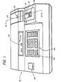
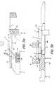
- FIGs. 1 and 2there is shown an analyzer 10 which comprises a load station 19, a metering station 20, a storage station 49 at which a storage chamber or incubator 50 is located, a pusher mechanism 40 for moving a test element E from the load station 19 to the station 20, and a detection station 109 at which a detector 110 is located.
- a transport means 57includes a loading member 60 for loading a test element E into incubator 50, an unloading member 80 for unloading an element from the incubator 50, and drive means 100 for driving the members 60 and 80 in a reciprocating motion.
- a pivotable cover 120is hinged at 122 to a bracket 124.
- Analyzer 10is capable of measuring a variety of analytes of liquids, particularly those of biological liquids. This is accomplished preferably through the use of test elements E which are generally flat (Fig. 2) and have one or more liquid-containing portions (not shown) mounted in a plastic frame member 15; the liquid-containing portions (not shown) are mounted on a transparent, liquid- impervious support (not shown). The liquid is applied by depositing a quantity, for example in the form of a drop, onto the test element E. Edges 16 and 17 of test element E define the leading and trailing edges, respectively, of the elements E as they are moved through the analyzer.
- test elements Epreferably are constructed in the manner described in, for example, US-A-3,992,158 and US ⁇ A ⁇ Re 30,267. Deposited sample liquid spreads into the layers (not shown) of element E where a reaction takes place that generates a detectable change.
- a molded portion 22 of cover 120is shaped to accommodate a conventional pipette (not shown). Portion 22 projects inwardly from the exterior surface 24 of cover 120 to form a shoulder 21 and terminates in a truncated cone 26 which includes an aperture 28. Cone 26 and aperture 28 are sized to align and support a pipette tip 29 (shown in dashed lines) such that a quantity of liquid can be dispensed therefrom onto a test element E.
- Cover 120includes, at front portion 30 thereof, a slot 32 sized to permit passage of the test element E.
- the test element Eis moved through the slot 32 by means of mechanism 40 which is mounted for manual actuation between a cover plate 41 and a support plate 42 (Fig. 3). Edge surfaces 43 of plate 41 are spaced at a distance sufficient to allow mechanism 40 to reciprocate between them.
- Support plate 42is mounted between two linear and parallel shoulders 44.
- the portion of plate 42 that extends under front portion 30 of cover 120comprises a slot 46 extending generally parallel to shoulders 44. Slot 46 permits loading member 60, discussed hereinafter, to engage test elements E located at metering station 20.
- Incubator 50is preferably collinear with the path travelled by mechanism 40 between edge surfaces 43 and is preferably constructed in the manner described in the aforesaid US ⁇ A ⁇ 4,303,611.
- Incubator 50comprises a first pair of walls 52 which are joined to a second pair of walls 54, a weighted cover 56, and camming means 58 adapted to raise cover 56 when a test element E is advanced into incubator 50.
- the wall 52 adjacent station 20is provided with a slot 59 which receives a finger 70 of loading member 60 when member 60 reaches its most advanced position (shown in solid lines in Fig. 2).
- the walls 52 and 54are dimensioned to receive test elements E in a stack S such that each element E, except for the uppermost element E, is covered and contacted by the test element E above it; the uppermost element E is covered by cover 56.
- Conventional heating elementsare preferably included in walls 52 and 54 to maintain the temperature of the incubator 50 at a desired level.
- Member 60is mounted for reciprocative movement under support plate 42 and within a passage defined by opposed surfaces 66 and supporting shoulders 68 (Fig. 3). Member 60 comprises a notch 62 (Fig. 3) which receives a rack 64 along its length thereof. As shown in Fig. 5a, member 60 is moved through positions A, B, and C, as will be explained in more detail hereinafter.
- Finger 70 (Fig. 2) on member 60is flexible and projects upwardly into the path of test elements E moved through metering station 20. Slots 46 and 59 are disposed to accommodate finger 70. Tip 72 of finger 70 is curved to provide a camming surface that engages support plate 42 when member 60 is retracted to its most rearward, or idle, position C (shown in dashed lines in Fig. 5a). The flexibility of finger 70 permits finger 70 to bend back under plate 42 and also permits a test element E to override the finger 70 and enter metering station 20, when member 60 occupies position A.
- Member 80is provided to unload test elements E from the stack S on a first-in, first-out basis.
- Member 80is mounted under member 60 (Fig. 2) for reciprocative movement through positions A', B', and C' as shown in Fig. 5b.
- Member 80comprises a notch 82 which receives a rack 84.
- Rack 84is located opposite to rack 64 such that the members 60 and 80 are driven in opposite directions by a pinion 106.
- Member 80is supported on shoulders 86, and members 60 and 80 are constrained to move along parallel paths which are spaced one above the other and are generally parallel to the path of movement of test elements E through analyzer 10.
- Member 80comprises an end portion 88 (Fig. 2) that is adapted to remove the bottommost element E from stack S in incubator 50.
- End portion 88comprises arms 90 and a raised shoulder 92 which are adapted to engage the bottommost element E, in the manner described in US ⁇ A ⁇ 4,302,420.
- a slot 93is provided in the wall 52 adjacent station 20 to allow arms 90 and shoulder 92, but not a test element, E, to pass therethrough. (See Fig. 5b).
- the opposite wall 52has a slot 95 which is sufficiently large to allow passage of arms 90 and the test elements E.
- a surface 97 on member 80, extending under the position occupied by test elements E carried by member 80,is preferably provided with white and dark reference coatings for detector 110.
- Arms 90include ends 94 having camming surfaces 96 thereon which are adapted to raise test elements E off detector 110 before sliding elements E relative to the detector 110, as described in the aforesaid US-A-4,302,402. This action by camming surface 96 prevents unnecessary wear on detector 110.
- a "continuous coupling”refers to a coupling that produces movement in both members 60 and 80 whenever drive means 100 is operative. In the disclosed arrangement, there is no necessity for means for disengaging the coupling when one of the members 60, 80, is not actively moving a test element E along its path.
- Drive means 100comprises a motor 102, a rotatable drive shaft 104, and pinion 106 mounted on shaft 104 (Fig. 2). Pinion 106 is continuously coupled to, or engaged with, both rack 64 and rack 84 (Fig. 3). Any reversible motor 102 is useful, for example, a stepper motor such as the motor manufactured by Airpex Co.
- detector 110is aligned with incubator 50 and metering station 20 and is a fiber optics reflectometer, constructed, for example, in the manner described in the aforesaid US-A-4,302,420.
- a fiber optics head 112is provided with at least one conventional light-emitting fiber 114 (Fig. 4).
- a plurality of conventional light-collecting fibers 116are bonded together as a coparallel bundle forming a face 118 at which the light is emitted and collected.
- Face 118is flat, as shown in Fig. 2, or slightly convexly curved.
- Weight 119forces a properly positioned test element E into contact with face 118.
- Detector 110preferably includes at least one light-emitting diode (not shown) connected to fiber 114 and a photodetector (not shown) connected to fibers 116.
- the advancement of the test elements E through stations 20, 49, and-109,is preferably done automatically, following the metering of the liquid at station 20.
- the devices (not shown) useful for such automatic controlinclude sensors, switches, and a microprocessor all of which are conventional devices. Display of the analyte concentration is acheived by conventional display devices, for example, a liquid crystal display 160 and/or a thermal printer 170 (Fig. 1).
- test element Eis placed in load station 19 on plate 42, as shown in Fig. 2.
- Manual operation of mechanism 40serves to push the test element E under pipette tip 29 which is positioned at metering station 20.
- the analyte for which that test element E is constructedis either keyed into the microprocessor (not shown) by using a command key 155 of a keyboard 150 (Fig. 1) or, preferably, appropriate code markings (not shown) on test element E are automatically sensed and recorded in the microprocessor (not shown).
- the liquid sampleis metered onto the test element E at station 20, and either an additional command is keyed into the microprocessor (not shown) when metering is complete, or a sensor (not shown) automatically generates that command.
- the subsequent sequence of movement of members 60 and 80is best illustrated in Figs. 5a and 5b.
- motor 102is automatically actuated to move member 60 and finger 70 to position A (Fig. 5a).
- finger 70engages trailing edge 17 of the test element E.
- motor 102also moves member 80 so that shoulder 92 is in the position A' (Fig. 5b).
- Motor 102is then actuated to advance member 60 and finger 70 to position B (shown in dashed lines in Fig. 5a).
- Camming means 58raises cover 56 during this movement so that a test element E can be loaded into incubator 50.
- member 80is moved rearwardly by motor 102 to position B' (Fig. 5b).
- the microprocessor(not shown) times the residence of all test elements E in incubator 50.
- motor 102is reversed, causing member 60 and finger 70 to be withdrawn from position B (Fig. 5a). Finger 70 passes through position A and retreats to position C shown in dashed lines (Fig. 5a).
- member 80advances from position B' (Fig. 5b) passes through position A' where it engages and unloads test element E from incubator 50, and moves to position C' (shown in dashed lines in Fig. 5b).
- shoulder 92is effective to transfer the test element E into detector 110.
- the test element E in detector 110is pushed out by the advancing test element E. After the last test element E is detected, it remains in detector 110 until a new test element E ejects it.
- member 80After member 80 is withdrawn to position A', the test. element E in detector 110 is read. The withdrawal of member 80 to position A' also acts to advance finger 70 from position C to position A, where it is in position to engage the next test element E that is moved into metering station 20.
- the density reading obtained by detector 110is converted by suitable, conventional programming of the microprocessor (not shown) into a concentration reading.
- the concentrationis displayed, for example, by display 160 and printer 170.
- Parts that are to convey heatare not critical, metals and plastics being the preferred choices.
- Parts that are to convey heatare preferably formed from metals.
Landscapes
- Physics & Mathematics (AREA)
- Health & Medical Sciences (AREA)
- Life Sciences & Earth Sciences (AREA)
- Chemical & Material Sciences (AREA)
- Analytical Chemistry (AREA)
- Biochemistry (AREA)
- General Health & Medical Sciences (AREA)
- General Physics & Mathematics (AREA)
- Immunology (AREA)
- Pathology (AREA)
- Automatic Analysis And Handling Materials Therefor (AREA)
Description
- The present invention relates to an analyzer for the chemical analysis of substances, known as analytes, in liquids. More specifically, the invention relates to an analyzer having apparatus for automatically advancing a test element through such an analyzer.
- US-A-4303611 describes an analyzer having an incubator for generally flat test elements in which the test elements are supported in the incubator in a vertical stack with adjacent test elements resting against each other. Such an arrangement has produced a greatly simplified analyzer in which the loss of gases from the test elements during incubation is substantially reduced.
- Although significant advantages are obtained by the disclosed arrangement, there is a problem in that one mechanism is required to load test elements onto the top of the stack in the incubator and a separately-driven mechanism is needed to unload test elements from the bottom of the stack upon completion of the incubation cycle. To accommodate the separate mechanisms in the analyzer, the mechanism for unloading test elements is disposed at an angle to the loading mechanism; such an arrangement makes it necessary to also locate the detection station at an angle to the path of test element movement into the incubator. Thus, the loading and unloading mechanisms are relatively complex and require a substantial amount of room in the analyzer.
- The present invention overcomes the problems noted above. The loading and unloading mechanisms are arranged such that a test element is moved through the analyzer in a generally linear path, and both the mechanisms are continuously coupled to a single drive means. The continuous coupling is achieved by providing for one member to move to an idle position when the other member is operative to advance a test element.
- In accordance with the present invention there is provided an analyzer for the chemical analysis of a liquid contained in a test element, said analyzer comprising a metering station, a storage station and a detection station, through which said test element is moved during the analysis of said liquid, and transport means for sequentially advancing said test element through said stations, said transport means comprising a loading member moveable from (1) an idle position upstream of said metering station, to (2) an element-engaging position at said metering station, and to (3) an element-loading position at said storage station, and back to the other positions while not disturbing said test elements, and an unloading member movable from (1') an idle position upstream of said storage station, to (2') an element-engaging position at said storage station, and to (3') an element-loading position at said detection station, and back to the other positions while not disturbing said test elements, characterized by a single reversible drive means simultaneously coupled to said loading member and said unloading member and which operates in one direction to move said loading member to its (1), (2), and (3) positions while synchronously moving said unloading member to its (3'), (2') and (1') position, and vice versa.
- It is an advantage of the present invention that the analyzer has a single drive means simultaneously driving both the loading and unloading mechanisms in a manner such that the loading and unloading functions occur independently. Such an arrangement provides for a greatly simplified device in which test elements can be advanced through the analyzer along a generally linear path.
- Embodiments of the present invention will now be described, by way of example, with reference to the accompanying drawings in which:
- Fig. 1 is a perspective view of an analyzer constructed in accordance with the present invention.
- Fig. 2 is a fragmentary elevational view, in section, taken generally along the line II-II of Fig. 1 ;
- Fig. 3 is a section view taken generally along the line III-III of Fig. 2;
- Fig. 4 is a plan view of the face of the fiber optics reflectometer; and
- Figs. 5a and 5b are enlarged section views, similar to a portion of Fig. 2, illustrating the steps in the operation of the analyzer.
- The specific embodiments hereinafter described refer to an analyzer having an incubator in which test elements contained therein are arranged in a stack, and the detector is a fiber optics reflectometer. The invention is a also applicable to an analyzer using any kind of storage chamber adapted to contain more than one test element. Further, it is applicable to an analyzer using any detector means for detecting properties of the test element, whether it be a reflectometer for measuring an optical density change, a fluorimeter for measuring fluorescence or phosphorescence in a test element, or some other kind of detector.
- The invention hereinafter described refers to blood serum as the preferred liquid under analysis. In addition, other analyte-containing liquids can be analyzed, including industrial liquids containing nonbiological analytes.
- In Figs. 1 and 2, there is shown an
analyzer 10 which comprises a load station 19, ametering station 20, astorage station 49 at which a storage chamber orincubator 50 is located, apusher mechanism 40 for moving a test element E from the load station 19 to thestation 20, and adetection station 109 at which adetector 110 is located. A transport means 57 includes aloading member 60 for loading a test element E intoincubator 50, anunloading member 80 for unloading an element from theincubator 50, and drive means 100 for driving themembers pivotable cover 120 is hinged at 122 to abracket 124. - Analyzer 10 is capable of measuring a variety of analytes of liquids, particularly those of biological liquids. This is accomplished preferably through the use of test elements E which are generally flat (Fig. 2) and have one or more liquid-containing portions (not shown) mounted in a plastic frame member 15; the liquid-containing portions (not shown) are mounted on a transparent, liquid- impervious support (not shown). The liquid is applied by depositing a quantity, for example in the form of a drop, onto the test
element E. Edges - The test elements E preferably are constructed in the manner described in, for example, US-A-3,992,158 and US―A―Re 30,267. Deposited sample liquid spreads into the layers (not shown) of element E where a reaction takes place that generates a detectable change.
- As shown in Fig. 2, a molded
portion 22 ofcover 120 is shaped to accommodate a conventional pipette (not shown).Portion 22 projects inwardly from theexterior surface 24 ofcover 120 to form ashoulder 21 and terminates in atruncated cone 26 which includes anaperture 28.Cone 26 andaperture 28 are sized to align and support a pipette tip 29 (shown in dashed lines) such that a quantity of liquid can be dispensed therefrom onto a test element E. Cover 120 includes, at front portion 30 thereof, aslot 32 sized to permit passage of the test element E. The test element E is moved through theslot 32 by means ofmechanism 40 which is mounted for manual actuation between a cover plate 41 and a support plate 42 (Fig. 3).Edge surfaces 43 of plate 41 are spaced at a distance sufficient to allowmechanism 40 to reciprocate between them.Support plate 42 is mounted between two linear andparallel shoulders 44. The portion ofplate 42 that extends under front portion 30 ofcover 120 comprises aslot 46 extending generally parallel toshoulders 44.Slot 46 permitsloading member 60, discussed hereinafter, to engage test elements E located atmetering station 20.- Incubator 50 is preferably collinear with the path travelled by
mechanism 40 betweenedge surfaces 43 and is preferably constructed in the manner described in the aforesaid US―A―4,303,611. Incubator 50 comprises a first pair ofwalls 52 which are joined to a second pair of walls 54, a weightedcover 56, andcamming means 58 adapted to raisecover 56 when a test element E is advanced intoincubator 50. Thewall 52adjacent station 20 is provided with aslot 59 which receives afinger 70 ofloading member 60 whenmember 60 reaches its most advanced position (shown in solid lines in Fig. 2). Thewalls 52 and 54 are dimensioned to receive test elements E in a stack S such that each element E, except for the uppermost element E, is covered and contacted by the test element E above it; the uppermost element E is covered bycover 56. Conventional heating elements (not shown) are preferably included inwalls 52 and 54 to maintain the temperature of theincubator 50 at a desired level. Member 60 is mounted for reciprocative movement undersupport plate 42 and within a passage defined byopposed surfaces 66 and supporting shoulders 68 (Fig. 3).Member 60 comprises a notch 62 (Fig. 3) which receives arack 64 along its length thereof. As shown in Fig. 5a,member 60 is moved through positions A, B, and C, as will be explained in more detail hereinafter.- Finger 70 (Fig. 2) on
member 60 is flexible and projects upwardly into the path of test elements E moved throughmetering station 20.Slots finger 70.Tip 72 offinger 70 is curved to provide a camming surface that engagessupport plate 42 whenmember 60 is retracted to its most rearward, or idle, position C (shown in dashed lines in Fig. 5a). The flexibility offinger 70 permitsfinger 70 to bend back underplate 42 and also permits a test element E to override thefinger 70 and entermetering station 20, whenmember 60 occupies position A. Member 80 is provided to unload test elements E from the stack S on a first-in, first-out basis.Member 80 is mounted under member 60 (Fig. 2) for reciprocative movement through positions A', B', and C' as shown in Fig. 5b.Member 80 comprises anotch 82 which receives arack 84. Rack 84 is located opposite torack 64 such that themembers pinion 106.Member 80 is supported onshoulders 86, andmembers analyzer 10.Member 80 comprises an end portion 88 (Fig. 2) that is adapted to remove the bottommost element E from stack S inincubator 50.End portion 88 comprisesarms 90 and a raisedshoulder 92 which are adapted to engage the bottommost element E, in the manner described in US―A―4,302,420. Aslot 93 is provided in thewall 52adjacent station 20 to allowarms 90 andshoulder 92, but not a test element, E, to pass therethrough. (See Fig. 5b). Theopposite wall 52 has aslot 95 which is sufficiently large to allow passage ofarms 90 and the test elementsE. A surface 97 onmember 80, extending under the position occupied by test elements E carried bymember 80, is preferably provided with white and dark reference coatings fordetector 110.- Forward movement of shoulder 9-2 toward
detector 110 serves to move the test element E under aweight 119 atdetector 110. During retraction ofshoulder 92 to the position B' (Fig. 5b), retaining springs (not shown) prevent rearward movement of the test element E at thedetector 110.Arms 90 include ends 94 having camming surfaces 96 thereon which are adapted to raise test elements E offdetector 110 before sliding elements E relative to thedetector 110, as described in the aforesaid US-A-4,302,402. This action by cammingsurface 96 prevents unnecessary wear ondetector 110. Members members members motor 102, arotatable drive shaft 104, andpinion 106 mounted on shaft 104 (Fig. 2).Pinion 106 is continuously coupled to, or engaged with, both rack 64 and rack 84 (Fig. 3). Anyreversible motor 102 is useful, for example, a stepper motor such as the motor manufactured by Airpex Co.- Preferably,
detector 110 is aligned withincubator 50 andmetering station 20 and is a fiber optics reflectometer, constructed, for example, in the manner described in the aforesaid US-A-4,302,420. Indetector 110, afiber optics head 112 is provided with at least one conventional light-emitting fiber 114 (Fig. 4). A plurality of conventional light-collectingfibers 116 are bonded together as a coparallel bundle forming aface 118 at which the light is emitted and collected. Face 118 is flat, as shown in Fig. 2, or slightly convexly curved.Weight 119 forces a properly positioned test element E into contact withface 118.Detector 110 preferably includes at least one light-emitting diode (not shown) connected tofiber 114 and a photodetector (not shown) connected tofibers 116. - The advancement of the test elements E through
stations station 20. The devices (not shown) useful for such automatic control include sensors, switches, and a microprocessor all of which are conventional devices. Display of the analyte concentration is acheived by conventional display devices, for example, aliquid crystal display 160 and/or a thermal printer 170 (Fig. 1). - The operation of
analyzer 10 will be readily apparent from the preceding description. A test element E is placed in load station 19 onplate 42, as shown in Fig. 2. Manual operation ofmechanism 40 serves to push the test element E under pipette tip 29 which is positioned atmetering station 20. The analyte for which that test element E is constructed is either keyed into the microprocessor (not shown) by using acommand key 155 of a keyboard 150 (Fig. 1) or, preferably, appropriate code markings (not shown) on test element E are automatically sensed and recorded in the microprocessor (not shown). The liquid sample is metered onto the test element E atstation 20, and either an additional command is keyed into the microprocessor (not shown) when metering is complete, or a sensor (not shown) automatically generates that command. The subsequent sequence of movement ofmembers metering station 20,motor 102 is automatically actuated to movemember 60 andfinger 70 to position A (Fig. 5a). Whenmember 60 andfinger 70 are in the A position,finger 70 engages trailingedge 17 of the test element E. Whenmember 60 is moved in this fashion,motor 102 also movesmember 80 so thatshoulder 92 is in the position A' (Fig. 5b).Motor 102 is then actuated to advancemember 60 andfinger 70 to position B (shown in dashed lines in Fig. 5a). Camming means 58 raises cover 56 during this movement so that a test element E can be loaded intoincubator 50. Simultaneously,member 80 is moved rearwardly bymotor 102 to position B' (Fig. 5b). - The microprocessor (not shown) times the residence of all test elements E in
incubator 50. When the timing sequence dictates that the bottommost element E inincubator 50 is to be unloaded,motor 102 is reversed, causingmember 60 andfinger 70 to be withdrawn from position B (Fig. 5a).Finger 70 passes through position A and retreats to position C shown in dashed lines (Fig. 5a). During the same time,member 80 advances from position B' (Fig. 5b) passes through position A' where it engages and unloads test element E fromincubator 50, and moves to position C' (shown in dashed lines in Fig. 5b). In position C',shoulder 92 is effective to transfer the test element E intodetector 110. The test element E indetector 110 is pushed out by the advancing test element E. After the last test element E is detected, it remains indetector 110 until a new test element E ejects it. - After
member 80 is withdrawn to position A', the test. element E indetector 110 is read. The withdrawal ofmember 80 to position A' also acts to advancefinger 70 from position C to position A, where it is in position to engage the next test element E that is moved intometering station 20. - It will be apparent, therefore, that as
member 60 is advancing to load elements E intoincubator 50,member 80 is withdrawing in a manner that leaves undisturbed the elements in stack S. Whenmember 80 advances to unload an element E in stack S,member 60 withdraws without disturbing test elements E being- prepared for loading on stack S. Only one of themembers incubator 50. - The density reading obtained by
detector 110 is converted by suitable, conventional programming of the microprocessor (not shown) into a concentration reading. The concentration is displayed, for example, bydisplay 160 andprinter 170. - The materials used to make the parts described above are not critical, metals and plastics being the preferred choices. Parts that are to convey heat, such as
walls 52, 54, and cover 56, are preferably formed from metals.
Claims (5)
Applications Claiming Priority (2)
| Application Number | Priority Date | Filing Date | Title |
|---|---|---|---|
| US354859 | 1982-03-04 | ||
| US06/354,859US4424191A (en) | 1982-03-04 | 1982-03-04 | Analyzer featuring loading and unloading means for a storage chamber, and common drive means |
Publications (2)
| Publication Number | Publication Date |
|---|---|
| EP0088601A1 EP0088601A1 (en) | 1983-09-14 |
| EP0088601B1true EP0088601B1 (en) | 1987-04-15 |
Family
ID=23395209
Family Applications (1)
| Application Number | Title | Priority Date | Filing Date |
|---|---|---|---|
| EP83301163AExpiredEP0088601B1 (en) | 1982-03-04 | 1983-03-04 | Analyzer for chemical analysis of a liquid |
Country Status (5)
| Country | Link |
|---|---|
| US (1) | US4424191A (en) |
| EP (1) | EP0088601B1 (en) |
| JP (1) | JPS58161867A (en) |
| CA (1) | CA1174872A (en) |
| DE (1) | DE3371001D1 (en) |
Cited By (1)
| Publication number | Priority date | Publication date | Assignee | Title |
|---|---|---|---|---|
| US8417013B2 (en) | 2008-03-04 | 2013-04-09 | 3M Innovative Properties Company | Information management in automated processing of biological growth media |
Families Citing this family (47)
| Publication number | Priority date | Publication date | Assignee | Title |
|---|---|---|---|---|
| US4566798A (en)* | 1983-11-10 | 1986-01-28 | Eastman Kodak Company | Method for calibrating a reflectometer containing black and white references displaced from the sample position |
| US4710352A (en)* | 1985-09-20 | 1987-12-01 | Eastman Kodak Company | Simplified test element advancing mechanism having positive engagement with element |
| US4695430A (en)* | 1985-10-31 | 1987-09-22 | Bio/Data Corporation | Analytical apparatus |
| US4798705A (en)* | 1985-12-24 | 1989-01-17 | Eastman Kodak Company | Compact analyzer |
| US5169600A (en)* | 1987-07-15 | 1992-12-08 | Fuji Photo Film Co., Ltd. | Biochemical analysis apparatus for incubating and analyzing test sites on a long tape test film |
| US5108708A (en)* | 1988-06-22 | 1992-04-28 | The United States Of America As Represented By The Secretary Of The Department Of Health And Human Services | Aliquot collection adapter for HPLC automatic injector enabling simultaneous sample analysis and sample collection |
| US5059393A (en)* | 1989-01-05 | 1991-10-22 | Eastman Kodak Company | Analysis slide positioning apparatus and method for a chemical analyzer |
| US5053198A (en)* | 1989-02-14 | 1991-10-01 | Eastman Kodak Company | Used test element collection apparatus and method |
| CA2015910C (en)* | 1989-05-09 | 1995-01-03 | James David Shaw | Flexible pusher blade and housing |
| US5250262A (en)* | 1989-11-22 | 1993-10-05 | Vettest S.A. | Chemical analyzer |
| US5089229A (en)* | 1989-11-22 | 1992-02-18 | Vettest S.A. | Chemical analyzer |
| JP2618727B2 (en)* | 1990-01-19 | 1997-06-11 | 富士写真フイルム株式会社 | Method for quantifying test components in whole blood |
| US5089418A (en)* | 1990-03-28 | 1992-02-18 | Eastman Kodak Company | Analyzer featuring a circular track of cartridges centered on an incubator and method of use |
| US5176202A (en)* | 1991-03-18 | 1993-01-05 | Cryo-Cell International, Inc. | Method and apparatus for use in low-temperature storage |
| US5174960A (en)* | 1990-11-19 | 1992-12-29 | Eastman Kodak Company | Apparatus for shuttling a test element from a discharge path to a wash station |
| EP0734435B1 (en)* | 1993-12-17 | 1999-03-31 | Minnesota Mining And Manufacturing Company | Automated incubating and imaging apparatus for disposable microorganism culturing media |
| US5419871A (en)* | 1994-04-29 | 1995-05-30 | Muszak; Martin F. | Analyzer elevator assembly |
| JP3624203B2 (en)* | 1995-10-26 | 2005-03-02 | アークレイ株式会社 | Analysis equipment |
| EP0901634B1 (en)* | 1996-05-30 | 2002-03-20 | Radiometer Medical A/S | A system for determining at least one parameter of at least one sample of a physiological liquid and a cassette |
| US20020064884A1 (en)* | 2000-11-30 | 2002-05-30 | Devlin William Jackson | Method for automatically storing and reprocessing patient specimen's in an automatic clinical analyzer |
| US20020064881A1 (en)* | 2000-11-30 | 2002-05-30 | Devlin William Jackson | Method for automatically storing and reprocessing patient specimen's in an automatic clinical analyzer |
| US6936224B2 (en)* | 2001-06-21 | 2005-08-30 | Perseptive Biosystems, Inc. | Apparatus and process for transporting sample plates |
| US6941234B2 (en) | 2001-10-17 | 2005-09-06 | Midtronics, Inc. | Query based electronic battery tester |
| US7319031B2 (en) | 2002-11-27 | 2008-01-15 | 3M Innovative Properties Company | Mounting platform for biological growth plate scanner |
| US20040101954A1 (en) | 2002-11-27 | 2004-05-27 | Graessle Josef A. | Back side plate illumination for biological growth plate scanner |
| US20040102903A1 (en) | 2002-11-27 | 2004-05-27 | Graessle Josef A. | Biological growth plate scanner |
| US7298885B2 (en) | 2002-11-27 | 2007-11-20 | 3M Innovative Properties Company | Biological growth plate scanner with automated image processing profile selection |
| US7351574B2 (en) | 2002-11-27 | 2008-04-01 | 3M Innovative Properties Company | Loading and ejection systems for biological growth plate scanner |
| AU2003296703A1 (en)* | 2002-12-23 | 2004-07-14 | F.Hoffmann-La Roche Ag | Transport device for transporting test strips in an analysis system |
| US7273591B2 (en)* | 2003-08-12 | 2007-09-25 | Idexx Laboratories, Inc. | Slide cartridge and reagent test slides for use with a chemical analyzer, and chemical analyzer for same |
| US7496225B2 (en) | 2003-09-04 | 2009-02-24 | 3M Innovative Properties Company | Biological growth plate scanner with automated intake |
| US7298886B2 (en) | 2003-09-05 | 2007-11-20 | 3M Innovative Properties Company | Counting biological agents on biological growth plates |
| US7588733B2 (en) | 2003-12-04 | 2009-09-15 | Idexx Laboratories, Inc. | Retaining clip for reagent test slides |
| US7553451B2 (en)* | 2004-09-29 | 2009-06-30 | Cytyc Corporation | Platform apparatus with horizontal slide translation and method |
| WO2006092980A1 (en) | 2005-02-28 | 2006-09-08 | Fujifilm Corporation | Dry analysis element |
| WO2008140742A1 (en)* | 2007-05-08 | 2008-11-20 | Idexx Laboratories, Inc. | Chemical analyzer |
| EP2597146A1 (en) | 2007-07-09 | 2013-05-29 | 3M Innovative Properties Company of 3M Center | Modular system for detecting microorganisms |
| EP2065708B1 (en) | 2007-11-28 | 2014-01-01 | FUJIFILM Corporation | Method for measuring high-density lipoprotein cholesterol |
| US9933446B2 (en) | 2008-03-04 | 2018-04-03 | 3M Innovative Properties Company | Processing of biological growth media based on measured manufacturing characteristics |
| JP4889670B2 (en) | 2008-03-26 | 2012-03-07 | 富士フイルム株式会社 | Dry analytical element for measuring body fluid components with reduced hemolysis |
| JP5313537B2 (en) | 2008-04-10 | 2013-10-09 | 富士フイルム株式会社 | Dry analytical element for high density lipoprotein cholesterol measurement |
| JP5543798B2 (en)* | 2009-03-25 | 2014-07-09 | 富士フイルム株式会社 | Method for measuring low density lipoprotein cholesterol |
| JP5285000B2 (en)* | 2010-02-23 | 2013-09-11 | 富士フイルム株式会社 | Method for measuring low density lipoprotein cholesterol |
| JP5355674B2 (en) | 2011-01-11 | 2013-11-27 | 富士フイルム株式会社 | Method for removing high density lipoprotein in blood |
| WO2015106008A1 (en) | 2014-01-10 | 2015-07-16 | Idexx Laboratories, Inc. | Chemical analyzer |
| IT201800005662A1 (en) | 2018-05-24 | 2019-11-24 | Method for the construction of a wall, a floor or the like formed by a plurality of interconnected wooden panels, a wall implemented with this method and a connecting element for wooden panels, in particular wooden panels with crossed layers glued or mechanically joined for the construction of a wall of this type | |
| CA3185353A1 (en) | 2020-07-10 | 2022-01-13 | Jonathan W. LAWRENCE | Point-of-care medical diagnostic analyzer and devices, systems, and methods for medical diagnostic analysis of samples |
Citations (1)
| Publication number | Priority date | Publication date | Assignee | Title |
|---|---|---|---|---|
| US4302420A (en)* | 1981-01-09 | 1981-11-24 | Eastman Kodak Company | Analyzer featuring a contacting reflectometer |
Family Cites Families (10)
| Publication number | Priority date | Publication date | Assignee | Title |
|---|---|---|---|---|
| DE1250160B (en)* | 1960-10-10 | |||
| US3418084A (en)* | 1966-10-27 | 1968-12-24 | Instrumentation Specialties Co | Rectangular fraction collector |
| US3955930A (en) | 1975-04-07 | 1976-05-11 | Justin Joel Shapiro | Automatic dilutor having coupled diluent and reagent plungers |
| US4152390A (en)* | 1976-12-17 | 1979-05-01 | Eastman Kodak Company | Chemical analyzer |
| US4142656A (en) | 1976-12-17 | 1979-03-06 | Eastman Kodak Company | Drop former utilizing gas pressure |
| US4298571A (en) | 1976-12-17 | 1981-11-03 | Eastman Kodak Company | Incubator including cover means for an analysis slide |
| US4269803A (en) | 1979-07-02 | 1981-05-26 | Eastman Kodak Company | Slide transfer mechanism |
| US4321122A (en) | 1980-03-31 | 1982-03-23 | Eastman Kodak Company | Apparatus for forming electrical contact with an analysis slide |
| US4296069A (en) | 1980-06-16 | 1981-10-20 | Eastman Kodak Company | Apparatus for processing an analysis slide |
| US4303611A (en) | 1980-08-11 | 1981-12-01 | Eastman Kodak Company | Analyzer apparatus featuring a simplified incubator |
- 1982
- 1982-03-04USUS06/354,859patent/US4424191A/ennot_activeExpired - Lifetime
- 1982-08-10CACA000409098Apatent/CA1174872A/ennot_activeExpired
- 1983
- 1983-03-01JPJP58033694Apatent/JPS58161867A/enactiveGranted
- 1983-03-04DEDE8383301163Tpatent/DE3371001D1/ennot_activeExpired
- 1983-03-04EPEP83301163Apatent/EP0088601B1/ennot_activeExpired
Patent Citations (1)
| Publication number | Priority date | Publication date | Assignee | Title |
|---|---|---|---|---|
| US4302420A (en)* | 1981-01-09 | 1981-11-24 | Eastman Kodak Company | Analyzer featuring a contacting reflectometer |
Cited By (1)
| Publication number | Priority date | Publication date | Assignee | Title |
|---|---|---|---|---|
| US8417013B2 (en) | 2008-03-04 | 2013-04-09 | 3M Innovative Properties Company | Information management in automated processing of biological growth media |
Also Published As
| Publication number | Publication date |
|---|---|
| US4424191A (en) | 1984-01-03 |
| JPH0352828B2 (en) | 1991-08-13 |
| CA1174872A (en) | 1984-09-25 |
| EP0088601A1 (en) | 1983-09-14 |
| DE3371001D1 (en) | 1987-05-21 |
| JPS58161867A (en) | 1983-09-26 |
Similar Documents
| Publication | Publication Date | Title |
|---|---|---|
| EP0088601B1 (en) | Analyzer for chemical analysis of a liquid | |
| US4152390A (en) | Chemical analyzer | |
| AU671663B2 (en) | Assay module transport apparatus for use in an automated analytical instrument | |
| US4302420A (en) | Analyzer featuring a contacting reflectometer | |
| CA1217790A (en) | Method and apparatus for storing and dispensing analysis slides | |
| US5518688A (en) | Automated analytical instrument having a fluid sample holding tray transport assembly | |
| US9823109B2 (en) | Chemical analyzer | |
| EP0148203B1 (en) | Apparatus for processing analysis slides | |
| AU630847B2 (en) | Slide analysis system | |
| US4731225A (en) | Automatic analysis apparatus | |
| EP0216616B1 (en) | Test element advancing mechanism having positive engagement with element | |
| EP3361261A1 (en) | Specimen rack transfer device and automatic analysis system | |
| CA1099951A (en) | Automatic chemical analysis of biological fluids | |
| US5674454A (en) | Stacking disposal system for test sample cards or other similarly shaped objects | |
| GB2116711A (en) | Automatic chemical analysis | |
| EP0301743B1 (en) | Analyzer with wash station separate from incubator | |
| EP0620440A2 (en) | Analytic test sheet feeder | |
| JPH0353172Y2 (en) | ||
| JPH05264557A (en) | Test piece feeder |
Legal Events
| Date | Code | Title | Description |
|---|---|---|---|
| PUAI | Public reference made under article 153(3) epc to a published international application that has entered the european phase | Free format text:ORIGINAL CODE: 0009012 | |
| AK | Designated contracting states | Designated state(s):DE FR GB | |
| 17P | Request for examination filed | Effective date:19840210 | |
| GRAA | (expected) grant | Free format text:ORIGINAL CODE: 0009210 | |
| AK | Designated contracting states | Kind code of ref document:B1 Designated state(s):DE FR GB | |
| REF | Corresponds to: | Ref document number:3371001 Country of ref document:DE Date of ref document:19870521 | |
| ET | Fr: translation filed | ||
| PLBE | No opposition filed within time limit | Free format text:ORIGINAL CODE: 0009261 | |
| STAA | Information on the status of an ep patent application or granted ep patent | Free format text:STATUS: NO OPPOSITION FILED WITHIN TIME LIMIT | |
| 26N | No opposition filed | ||
| PGFP | Annual fee paid to national office [announced via postgrant information from national office to epo] | Ref country code:GB Payment date:19940221 Year of fee payment:12 | |
| PGFP | Annual fee paid to national office [announced via postgrant information from national office to epo] | Ref country code:FR Payment date:19940315 Year of fee payment:12 | |
| PG25 | Lapsed in a contracting state [announced via postgrant information from national office to epo] | Ref country code:GB Effective date:19950304 | |
| GBPC | Gb: european patent ceased through non-payment of renewal fee | Effective date:19950304 | |
| PG25 | Lapsed in a contracting state [announced via postgrant information from national office to epo] | Ref country code:FR Free format text:LAPSE BECAUSE OF NON-PAYMENT OF DUE FEES Effective date:19951130 | |
| REG | Reference to a national code | Ref country code:FR Ref legal event code:ST | |
| PGFP | Annual fee paid to national office [announced via postgrant information from national office to epo] | Ref country code:DE Payment date:19970307 Year of fee payment:15 | |
| PG25 | Lapsed in a contracting state [announced via postgrant information from national office to epo] | Ref country code:DE Free format text:LAPSE BECAUSE OF NON-PAYMENT OF DUE FEES Effective date:19981201 |