EP0086552B1 - Bone fracture fixation nail - Google Patents
Bone fracture fixation nailDownload PDFInfo
- Publication number
- EP0086552B1 EP0086552B1EP83300142AEP83300142AEP0086552B1EP 0086552 B1EP0086552 B1EP 0086552B1EP 83300142 AEP83300142 AEP 83300142AEP 83300142 AEP83300142 AEP 83300142AEP 0086552 B1EP0086552 B1EP 0086552B1
- Authority
- EP
- European Patent Office
- Prior art keywords
- end portion
- midportion
- bone
- generally
- nail according
- Prior art date
- Legal status (The legal status is an assumption and is not a legal conclusion. Google has not performed a legal analysis and makes no representation as to the accuracy of the status listed.)
- Expired
Links
- 208000010392Bone FracturesDiseases0.000title1
- 210000000988bone and boneAnatomy0.000claimsdescription24
- 230000000087stabilizing effectEffects0.000claimsdescription7
- 238000003780insertionMethods0.000claimsdescription5
- 230000037431insertionEffects0.000claimsdescription5
- 229910052751metalInorganic materials0.000claimsdescription5
- 239000002184metalSubstances0.000claimsdescription5
- 210000002758humerusAnatomy0.000description13
- 229910000771VitalliumInorganic materials0.000description3
- 239000000602vitalliumSubstances0.000description3
- 238000005452bendingMethods0.000description2
- 238000010276constructionMethods0.000description2
- 238000001356surgical procedureMethods0.000description2
- 210000000689upper legAnatomy0.000description2
- VYZAMTAEIAYCRO-UHFFFAOYSA-NChromiumChemical compound[Cr]VYZAMTAEIAYCRO-UHFFFAOYSA-N0.000description1
- WAIPAZQMEIHHTJ-UHFFFAOYSA-N[Cr].[Co]Chemical class[Cr].[Co]WAIPAZQMEIHHTJ-UHFFFAOYSA-N0.000description1
- 230000002411adverseEffects0.000description1
- 239000000560biocompatible materialSubstances0.000description1
- 229910052804chromiumInorganic materials0.000description1
- 239000011651chromiumSubstances0.000description1
- 229910017052cobaltInorganic materials0.000description1
- 239000010941cobaltSubstances0.000description1
- GUTLYIVDDKVIGB-UHFFFAOYSA-Ncobalt atomChemical compound[Co]GUTLYIVDDKVIGB-UHFFFAOYSA-N0.000description1
- 238000005260corrosionMethods0.000description1
- 230000007797corrosionEffects0.000description1
- 238000006073displacement reactionMethods0.000description1
- -1e.g.Substances0.000description1
- 230000000694effectsEffects0.000description1
- 210000003414extremityAnatomy0.000description1
- 230000005484gravityEffects0.000description1
- 239000000463materialSubstances0.000description1
- 239000000203mixtureSubstances0.000description1
- 238000010079rubber tappingMethods0.000description1
- 230000006641stabilisationEffects0.000description1
- 238000011105stabilizationMethods0.000description1
- 239000010935stainless steelSubstances0.000description1
- 229910001220stainless steelInorganic materials0.000description1
- 210000001519tissueAnatomy0.000description1
Images
Classifications
- A—HUMAN NECESSITIES
- A61—MEDICAL OR VETERINARY SCIENCE; HYGIENE
- A61B—DIAGNOSIS; SURGERY; IDENTIFICATION
- A61B17/00—Surgical instruments, devices or methods
- A61B17/56—Surgical instruments or methods for treatment of bones or joints; Devices specially adapted therefor
- A61B17/58—Surgical instruments or methods for treatment of bones or joints; Devices specially adapted therefor for osteosynthesis, e.g. bone plates, screws or setting implements
- A61B17/68—Internal fixation devices, including fasteners and spinal fixators, even if a part thereof projects from the skin
- A61B17/72—Intramedullary devices, e.g. pins or nails
- A61B17/7208—Flexible pins, e.g. ENDER pins
Definitions
- the present inventionrelates to a prosthetic device for stabilizing fractures in bones and particularly, to an elongated prosthetic nail for stabilizing fractures in a region of a bone, e.g., a femur or the humerus.
- pins or nailsfor the purpose of attempting to stabilize certain types of fractures, for example, comminuted or complex fractures which are best treated by stabilization or internal fixation of the bone.
- Such pins or nailsare described and illustrated in U.S. Patent Nos. 2,579,968; 2,998,007; 3,433,220 and 3,439,671.
- the pins which are illustrated for example in the aforementioned '968 patentalthough providing for connection of the broken pieces of bone, do not provide for rotational stability because of their rod-like construction.
- most of these known nails or pinsdo not provide for any securement of the same to a portion of the bone.
- U.S. Patent No. 4,011,863(as defined in the pre-characterising portion of claim 1) discloses an elongated configurated prosthetic nail which is flat along the length and has two upturned end portions.
- the nail according to the '863 patentis not appropriate for use in bones where the intramedullary canal is not of a generally cylindrical nature or constant cross-section along its length.
- such nailcannot be satisfactorily used in the humerus bone of the human body since the humerus has a region which is varyingly elliptical in cross section at the junction of the middle and distant thirds of the humeral bone.
- the nail of the '863 patentmay be useful for the femur, it would not be satisfactory for use in the humerus or like bones which have an elliptical or varying elliptical configuration in cross section along the length of the bone.
- the present inventionrelates to a prosthetic nail for stabilizing fractures of a bone having an intramedullary canal, comprising a continuous length of biocompatible metal having a first end portion terminating in an arcuate blunt ended configuration, a second end portion configured so as to be capable of being secured to the bone, and an elongated midportion positioned between the first and the second end portions, the midportion having a twisted configuration and together with said first end portion being configured and dimensioned for insertion into the intramedullary canal of the bone.
- the present inventionrelates to a prosthetic nail for stabilizing fractures of a bone having an intramedullary canal, comprising a continuous length of biocompatible metal having a first end portion terminating in a generally upturned arcuate blunt ended configuration, a second end portion being generally upturned in generally the same direction as the first end portion and being configured so as to be capable of being secured to the bone, and an elongated midportion having a twisted configuration generally along its length and together with the first end portion being configured and dimensioned for insertion into the intramedullary canal of the bone.
- the midportionis generally tapered in width along its length from the second end portion toward the first end portion. Also the midportion preferably is generally tapered in its thickness along its length from said second end portion toward said first end portion. Also the nail is generally tapered in its thickness along its length from the second end portion toward the first end portion.
- the second end portionis of a generally constant width and is of a generally squared-off configuration at its topmost upturned portion. The sides of the second end portion are generally parallel to each other.
- the first end portionis also of a generally constant width and the first end portion substantially continues the thickness of the thinner portion of said midportion.
- the second end portionincludes one or two holes configured and dimensioned for receiving means such as retaining screws for securing the second end portion to the bone.
- the holesare parallel and are disposed generally transverse to said midportion.
- a supracondylar prosthetic nailcomprises an elongated length of biocompatible metal having plan and elevational configurations, the plan configuration tapering from a relatively larger head to a rounded blunt tip, the elevational configuration having a relatively thin tapered elongated midportion and arcuate head and tip ends extending on the same side of said midportion, the midportion having at least a slightly twisted configuration generally along its length, the arcuate head end having ample inner and outer radii providing a thickness at the extremity similar to that of the plan head configuration, the arcuate tip end of the elevational configuration having relatively smaller radii smoothly continuing the smaller end of the midportion a short distance, and at least one hole for a retaining screw through the end of the head being disposed substantially at right angles to the midportion in the elevational configuration.
- the retaining screw holehas an axis disposed at right angles to the midportion of the nail in elevational configuration.
- the screw hold axisis disposed at slightly less than right angles to said midportion of the nail in elevational configuration.
- the plan configurationhas a tapered midportion and substantially parallel sided head and tip sections connected thereto, and the tapered midportion has a ratio of taper of about two to one from wider to narrower ends.
- the midportion in elevational configurationsubstantially continues the thickness of the thinner portion of the midportion.
- the head end in elevational configurationis squared off at its top and terminal sides about the retaining screw hole.
- FIG. 1a pair of prosthethic nails 10 and 12A according to the present invention are shown in FIG. 1 for securing a T-shaped fracture designated by phantom lines 14 in a region 16 of a bone 18 such as the humerus, which is partially shown in FIG. 1.
- Retaining screws 20secure the head of nails 10 and 12A to the area of humerus 18 and secure the split portions of humerus 18 together.
- Nails 10 and 12are inserted with their longer ends disposed within the intramedullary canal (not shown) of humerus 18.
- Prosthetic nails 10 and 12Amay be used for stabilizing various types of fractures of a region of the humerus either singly or in pairs.
- Nails 10 and 12A and retaining screws 20are made of a biocompatible metal such as stainless steel which is known under the tradename LVM 316.
- other suitable materiale.g., Vitallium may be used. Vitallium is the trademark of Howmedica, Inc., for a special cobalt-chromium alloy developed and used for cast partial and full dentures and for internal applications by surgeons. Cobalt and chromium constitute over 90% of its composition. Vitallium is characterized by a specific gravity of 8.29; tensile strength, 95,000 lb./sq.
- a nail 10is shown in a side elevational and top plan view, respectively. Also an end configuration is shown in FIG. 4.
- the nail 10has a substantially twisted thin midportion 22 disposed between a second end portion, i.e., an upwardly curved head end 24 and a first end portion, i.e., upwardly curved tip end 26.
- Midportion 22also preferably tapers from a maximum thickness at the head end 24 to a minimum thickness at the tip end 26.
- the head end 24is formed for example by an inner and outer radii which are different in dimension.
- the curved head portion 24extends longitudinally from the twisted midportion 22.
- the curved tip end 26extends longitudinally from the outer end of twisted midportion 22 and has parallel outer and inner radii, e.g., forming an arc of about 30°.
- the nail 10has a tapered intermediate portion I extending from the head end 24 from a distance H inside from the head of nail 10.
- the rest of the plan configuration of nail 10has parallel sides.
- Plan tip 28has a rounded blunt end of full radius.
- Head end 24 as shown in FIG. 2has square top and side ends, 30 and 32, which contain hole 34 for receiving retaining screw 20.
- Hole 34has its axis 36 disposed substantially perpendicular to the length of nail 10. This is described as a lateral configuration for retaining screw 20.
- FIG. 5shows what is described as a medial disposition for lag screw 20 by inclination of its axis 36A in a direction toward the first end position at an angle A of about 15° relative to a perpendicular line 38A to the length of nail 12A.
- FIG. 5also shows an alternative embodiment having two retaining screws 34A and 34B. Retaining screw holes 34, 34A and 34B have upper countersunk ends.
- the retaining screws 20may vary in length, as desired.
- Each screw 20has a tapered flat head with a hexagonal socket. The tip is pointed and has V-shaped self-tapping threads for firm bone engagement.
- the screw 20has a broad shank as illustrated in FIG. 10 of a six page Howmedica bulletin entitled “Howmedica Surgical Techniques: The Mouradian Humeral Fixation Device Surgical Technique” (hereinafter the "Howmedica bulletin”). This Howmedica bulletin is incorporated herein in its entirety as a reference.
- the twisted configuration of nails 10 and 12Aallows them to be used in the humerus whose shaft becomes elliptical by the junction of the middle and distal thirds and helps prevent rotational displacement of the implanted nail.
- the gentle taper over substantially the entire length of the nailsprovides variable resistance to bending in different portions of its length in a manner similar to that obtained by a varying layer spring.
- the blunt dull tip endprevents the wall of the intramedullary canal from being pierced.
- Nails 10 and 12Aare intended for use in stabilizing fractures in the proximal one-third area of the humerus, for repairing various types of fractures such as T-shaped, condylar or any other fracture therein.
- the nail 10 shown in FIG. 3has a clockwise twist as seen in the direction of the arrow "A".
- This nail 10is preferred for the right humerus which has an intramedullary canal which twists clockwise in the direction from the shoulderto the elbow.
- a pair of nailsone having a clockwise twist and the other having a counterclockwise twist can be used simultaneously in any given humerus.
- the pair of nailsare accordingly inserted in the greater and the lesser tuberosities, with the insertion in the former being directed to the lateral condyle and the latter to the medial condyle.
- the use and insertion of the prosthetic nailsare described in even greater detail in the Howmedica bulletin whose comments have been incorporated here in their entirety.
- the prosthetic nails according to the present inventionprovide not only for greater rotational and bending stability but also as well for proximal and distal fixation.
Landscapes
- Health & Medical Sciences (AREA)
- Orthopedic Medicine & Surgery (AREA)
- Surgery (AREA)
- Life Sciences & Earth Sciences (AREA)
- Heart & Thoracic Surgery (AREA)
- Animal Behavior & Ethology (AREA)
- Engineering & Computer Science (AREA)
- Biomedical Technology (AREA)
- Neurology (AREA)
- Medical Informatics (AREA)
- Molecular Biology (AREA)
- Nuclear Medicine, Radiotherapy & Molecular Imaging (AREA)
- General Health & Medical Sciences (AREA)
- Public Health (AREA)
- Veterinary Medicine (AREA)
- Surgical Instruments (AREA)
- Prostheses (AREA)
- Medicines Containing Material From Animals Or Micro-Organisms (AREA)
Description
- The present invention relates to a prosthetic device for stabilizing fractures in bones and particularly, to an elongated prosthetic nail for stabilizing fractures in a region of a bone, e.g., a femur or the humerus.
- It is well known to employ pins or nails for the purpose of attempting to stabilize certain types of fractures, for example, comminuted or complex fractures which are best treated by stabilization or internal fixation of the bone. Such pins or nails are described and illustrated in U.S. Patent Nos. 2,579,968; 2,998,007; 3,433,220 and 3,439,671. However, the pins which are illustrated for example in the aforementioned '968 patent, although providing for connection of the broken pieces of bone, do not provide for rotational stability because of their rod-like construction. In addition, most of these known nails or pins do not provide for any securement of the same to a portion of the bone.
- In an attempt to overcome the above-identified limitations of the prior art, U.S. Patent No. 4,011,863 (as defined in the pre-characterising portion of claim 1) discloses an elongated configurated prosthetic nail which is flat along the length and has two upturned end portions. However, the nail according to the '863 patent is not appropriate for use in bones where the intramedullary canal is not of a generally cylindrical nature or constant cross-section along its length. In particular, such nail cannot be satisfactorily used in the humerus bone of the human body since the humerus has a region which is varyingly elliptical in cross section at the junction of the middle and distant thirds of the humeral bone. Thus, although the nail of the '863 patent may be useful for the femur, it would not be satisfactory for use in the humerus or like bones which have an elliptical or varying elliptical configuration in cross section along the length of the bone.
- Also known in the art is the prosthetic nail of US-A-4169470 which is curved in two mutually normal longitudinal planes.
- The present invention relates to a prosthetic nail for stabilizing fractures of a bone having an intramedullary canal, comprising a continuous length of biocompatible metal having a first end portion terminating in an arcuate blunt ended configuration, a second end portion configured so as to be capable of being secured to the bone, and an elongated midportion positioned between the first and the second end portions, the midportion having a twisted configuration and together with said first end portion being configured and dimensioned for insertion into the intramedullary canal of the bone.
- In a preferred embodiment, the present invention relates to a prosthetic nail for stabilizing fractures of a bone having an intramedullary canal, comprising a continuous length of biocompatible metal having a first end portion terminating in a generally upturned arcuate blunt ended configuration, a second end portion being generally upturned in generally the same direction as the first end portion and being configured so as to be capable of being secured to the bone, and an elongated midportion having a twisted configuration generally along its length and together with the first end portion being configured and dimensioned for insertion into the intramedullary canal of the bone.
- The midportion is generally tapered in width along its length from the second end portion toward the first end portion. Also the midportion preferably is generally tapered in its thickness along its length from said second end portion toward said first end portion. Also the nail is generally tapered in its thickness along its length from the second end portion toward the first end portion. In addition, the second end portion is of a generally constant width and is of a generally squared-off configuration at its topmost upturned portion. The sides of the second end portion are generally parallel to each other. The first end portion is also of a generally constant width and the first end portion substantially continues the thickness of the thinner portion of said midportion.
- In order to permit securement of the nail to the bone, the second end portion includes one or two holes configured and dimensioned for receiving means such as retaining screws for securing the second end portion to the bone. Preferably the holes are parallel and are disposed generally transverse to said midportion.
- In a second preferred embodiment of the present invention, a supracondylar prosthetic nail comprises an elongated length of biocompatible metal having plan and elevational configurations, the plan configuration tapering from a relatively larger head to a rounded blunt tip, the elevational configuration having a relatively thin tapered elongated midportion and arcuate head and tip ends extending on the same side of said midportion, the midportion having at least a slightly twisted configuration generally along its length, the arcuate head end having ample inner and outer radii providing a thickness at the extremity similar to that of the plan head configuration, the arcuate tip end of the elevational configuration having relatively smaller radii smoothly continuing the smaller end of the midportion a short distance, and at least one hole for a retaining screw through the end of the head being disposed substantially at right angles to the midportion in the elevational configuration. The retaining screw hole has an axis disposed at right angles to the midportion of the nail in elevational configuration. In an alternative embodiment, the screw hold axis is disposed at slightly less than right angles to said midportion of the nail in elevational configuration. The plan configuration has a tapered midportion and substantially parallel sided head and tip sections connected thereto, and the tapered midportion has a ratio of taper of about two to one from wider to narrower ends. The midportion in elevational configuration substantially continues the thickness of the thinner portion of the midportion. The head end in elevational configuration is squared off at its top and terminal sides about the retaining screw hole.
- The present invention is described in detail below herein with reference to the drawings in which:
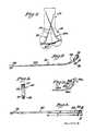
- FIG. 1 is a schematic view in elevation of a pair of prosthetic nails of a construction according to the present invention used to stabilize the fracture of a bone.
- FIG. 2 is an elevational longitudinal view of one of the prosthetic nails shown in FIG. 1.
- FIG. 3 is a top plan longitudinal view of the prosthetic nail shown in FIG. 2.
- FIG. 4 is a left end elevational view of the prosthetic nail shown in FIG. 2.
- FIG. 5 is a partial top plan longitudinal view of an alternative embodiment of the supracondylar prosthetic nail shown in FIG. 2 illustrating two retaining screw holes.
- In the description which follows, any reference to either orientation or direction is intended primarily for the purpose of illustration and is not intended in any way as a limitation of the scope of the present invention. Referring to the drawings, a pair of
prosthethic nails 10 and 12A according to the present invention are shown in FIG. 1 for securing a T-shaped fracture designated byphantom lines 14 in aregion 16 of a bone 18 such as the humerus, which is partially shown in FIG. 1. Retainingscrews 20 secure the head ofnails 10 and 12A to the area of humerus 18 and secure the split portions of humerus 18 together.Nails 10 and 12 are inserted with their longer ends disposed within the intramedullary canal (not shown) of humerus 18. Prosthetic nails 10 and 12A may be used for stabilizing various types of fractures of a region of the humerus either singly or in pairs.Nails 10 and 12A and retainingscrews 20 are made of a biocompatible metal such as stainless steel which is known under the tradename LVM 316. If desired, other suitable material, e.g., Vitallium may be used. Vitallium is the trademark of Howmedica, Inc., for a special cobalt-chromium alloy developed and used for cast partial and full dentures and for internal applications by surgeons. Cobalt and chromium constitute over 90% of its composition. Vitallium is characterized by a specific gravity of 8.29; tensile strength, 95,000 lb./sq. in minimum; 2% offset yield strength, 65,000 Ib./sq. in. minimum; reduction of area, 8% minimum, elongation 8% Ib./sq. in. When polished it is exceedingly smooth and permanently lustrous. Its outstanding qualities are clinical inertness in relation to living tissues and high degree of resistance to corrosion. Use of such biocompatible materials permits the prosthetic nail to be implanted in a human body without any adverse effects.- Referring to FIG. 2 and 3, a
nail 10 is shown in a side elevational and top plan view, respectively. Also an end configuration is shown in FIG. 4. Thenail 10 has a substantially twistedthin midportion 22 disposed between a second end portion, i.e., an upwardlycurved head end 24 and a first end portion, i.e., upwardlycurved tip end 26. The purpose of the twist will be explained in more detail below.Midportion 22 also preferably tapers from a maximum thickness at thehead end 24 to a minimum thickness at thetip end 26. Thehead end 24 is formed for example by an inner and outer radii which are different in dimension. Thecurved head portion 24 extends longitudinally from thetwisted midportion 22. Thecurved tip end 26 extends longitudinally from the outer end oftwisted midportion 22 and has parallel outer and inner radii, e.g., forming an arc of about 30°. - Referring to FIG. 3, the
nail 10 has a tapered intermediate portion I extending from thehead end 24 from a distance H inside from the head ofnail 10. The rest of the plan configuration ofnail 10 has parallel sides.Plan tip 28 has a rounded blunt end of full radius. - Head
end 24 as shown in FIG. 2 has square top and side ends, 30 and 32, which contain hole 34 for receiving retainingscrew 20. Hole 34 has its axis 36 disposed substantially perpendicular to the length ofnail 10. This is described as a lateral configuration for retainingscrew 20. FIG. 5 shows what is described as a medial disposition forlag screw 20 by inclination of itsaxis 36A in a direction toward the first end position at an angle A of about 15° relative to a perpendicular line 38A to the length of nail 12A. FIG. 5 also shows an alternative embodiment having two retainingscrews 34A and 34B. Retainingscrew holes 34, 34A and 34B have upper countersunk ends. - The
retaining screws 20 may vary in length, as desired. Eachscrew 20 has a tapered flat head with a hexagonal socket. The tip is pointed and has V-shaped self-tapping threads for firm bone engagement. In addition, thescrew 20 has a broad shank as illustrated in FIG. 10 of a six page Howmedica bulletin entitled "Howmedica Surgical Techniques: The Mouradian Humeral Fixation Device Surgical Technique" (hereinafter the "Howmedica bulletin"). This Howmedica bulletin is incorporated herein in its entirety as a reference. - The twisted configuration of
nails 10 and 12A allows them to be used in the humerus whose shaft becomes elliptical by the junction of the middle and distal thirds and helps prevent rotational displacement of the implanted nail. The gentle taper over substantially the entire length of the nails provides variable resistance to bending in different portions of its length in a manner similar to that obtained by a varying layer spring. The blunt dull tip end prevents the wall of the intramedullary canal from being pierced.Nails 10 and 12A are intended for use in stabilizing fractures in the proximal one-third area of the humerus, for repairing various types of fractures such as T-shaped, condylar or any other fracture therein. - The
nail 10 shown in FIG. 3 has a clockwise twist as seen in the direction of the arrow "A". Thisnail 10 is preferred for the right humerus which has an intramedullary canal which twists clockwise in the direction from the shoulderto the elbow. If desired, a pair of nails, one having a clockwise twist and the other having a counterclockwise twist can be used simultaneously in any given humerus. In such case, the pair of nails are accordingly inserted in the greater and the lesser tuberosities, with the insertion in the former being directed to the lateral condyle and the latter to the medial condyle. The use and insertion of the prosthetic nails are described in even greater detail in the Howmedica bulletin whose comments have been incorporated here in their entirety. - Thus, the prosthetic nails according to the present invention provide not only for greater rotational and bending stability but also as well for proximal and distal fixation.
Claims (10)
Applications Claiming Priority (2)
| Application Number | Priority Date | Filing Date | Title |
|---|---|---|---|
| US339513 | 1982-01-15 | ||
| US06/339,513US4503847A (en) | 1982-01-15 | 1982-01-15 | Prosthetic nail |
Publications (2)
| Publication Number | Publication Date |
|---|---|
| EP0086552A1 EP0086552A1 (en) | 1983-08-24 |
| EP0086552B1true EP0086552B1 (en) | 1986-07-02 |
Family
ID=23329347
Family Applications (1)
| Application Number | Title | Priority Date | Filing Date |
|---|---|---|---|
| EP83300142AExpiredEP0086552B1 (en) | 1982-01-15 | 1983-01-12 | Bone fracture fixation nail |
Country Status (9)
| Country | Link |
|---|---|
| US (1) | US4503847A (en) |
| EP (1) | EP0086552B1 (en) |
| AU (1) | AU540266B2 (en) |
| DE (1) | DE3364286D1 (en) |
| DK (1) | DK14183A (en) |
| ES (1) | ES8402502A1 (en) |
| FI (1) | FI71872C (en) |
| IE (1) | IE53790B1 (en) |
| NO (1) | NO830113L (en) |
Cited By (1)
| Publication number | Priority date | Publication date | Assignee | Title |
|---|---|---|---|---|
| US10251682B2 (en) | 2017-03-22 | 2019-04-09 | DePuy Synthes Products, Inc. | Distal radius nail |
Families Citing this family (52)
| Publication number | Priority date | Publication date | Assignee | Title |
|---|---|---|---|---|
| RO89820B1 (en)* | 1985-11-05 | 2002-06-28 | îNTREPRINDEREA INDUSTRIA TEHNICO MEDICALA | Elastic implants for a stable elastic osteorrhaphy of femoral and tibial fractures, respectively, as well as corresponding instrumentation |
| US4790303A (en)* | 1987-03-11 | 1988-12-13 | Acromed Corporation | Apparatus and method for securing bone graft |
| US5066296A (en)* | 1989-02-02 | 1991-11-19 | Pfizer Hopsital Products Group, Inc. | Apparatus for treating a fracture |
| GB2256802B (en)* | 1991-06-01 | 1995-10-25 | Dr Subhash Chandra Halder | Improvements in or relating to bone support |
| US5472444A (en)* | 1994-05-13 | 1995-12-05 | Acumed, Inc. | Humeral nail for fixation of proximal humeral fractures |
| US5766174A (en)* | 1995-09-26 | 1998-06-16 | Orthologic Corporation | Intramedullary bone fixation device |
| US5776194A (en)* | 1996-04-25 | 1998-07-07 | Nuvana Medical Innovations, Llc | Intermedullary rod apparatus and methods of repairing proximal humerus fractures |
| DE69624008T2 (en)* | 1996-12-02 | 2003-05-22 | Synthes Ag Chur, Chur | FLAT MARKEL NAIL |
| US6296641B2 (en)* | 1998-04-03 | 2001-10-02 | Bionx Implants Oy | Anatomical fixation implant |
| US6010506A (en)* | 1998-09-14 | 2000-01-04 | Smith & Nephew, Inc. | Intramedullary nail hybrid bow |
| US7008425B2 (en) | 1999-05-27 | 2006-03-07 | Jonathan Phillips | Pediatric intramedullary nail and method |
| CA2391062C (en) | 1999-11-11 | 2008-01-08 | Synthes (U.S.A.) | Radially expandable intramedullary nail |
| US6706046B2 (en)* | 2000-02-01 | 2004-03-16 | Hand Innovations, Inc. | Intramedullary fixation device for metaphyseal long bone fractures and methods of using the same |
| US20040153073A1 (en)* | 2000-02-01 | 2004-08-05 | Hand Innovations, Inc. | Orthopedic fixation system including plate element with threaded holes having divergent axes |
| US6562042B2 (en) | 2000-02-02 | 2003-05-13 | Owen A. Nelson | Orthopedic implant used to repair intertrochanteric fractures and a method for inserting the same |
| US6409730B1 (en) | 2000-05-31 | 2002-06-25 | Synthes (Usa) | Humeral spiral blade |
| US6527775B1 (en) | 2000-09-22 | 2003-03-04 | Piper Medical, Inc. | Intramedullary interlocking fixation device for the distal radius |
| KR100423699B1 (en)* | 2000-12-27 | 2004-03-19 | 최인호 | nail for the treatment of bone fractures |
| US7780664B2 (en) | 2002-12-10 | 2010-08-24 | Depuy Products, Inc. | Endosteal nail |
| US7635365B2 (en) | 2003-08-28 | 2009-12-22 | Ellis Thomas J | Bone plates |
| CA2548469A1 (en)* | 2003-12-01 | 2005-06-16 | Smith & Nephew, Inc. | Humeral nail with insert for fixing a screw |
| US7771428B2 (en) | 2004-06-11 | 2010-08-10 | Synthes Usa, Llc | Intramedullary rod with spiraling flutes |
| JP5060308B2 (en)* | 2004-12-31 | 2012-10-31 | シンセス ゲゼルシャフト ミット ベシュレンクテル ハフツング | Intramedullary nail |
| US7410488B2 (en) | 2005-02-18 | 2008-08-12 | Smith & Nephew, Inc. | Hindfoot nail |
| US9060820B2 (en) | 2005-05-18 | 2015-06-23 | Sonoma Orthopedic Products, Inc. | Segmented intramedullary fracture fixation devices and methods |
| US20060264951A1 (en)* | 2005-05-18 | 2006-11-23 | Nelson Charles L | Minimally Invasive Actuable Bone Fixation Devices Having a Retractable Interdigitation Process |
| US8961516B2 (en) | 2005-05-18 | 2015-02-24 | Sonoma Orthopedic Products, Inc. | Straight intramedullary fracture fixation devices and methods |
| JP2009512522A (en)* | 2005-10-21 | 2009-03-26 | アキュームド・エルエルシー | Orthopedic rod with a clamping opening |
| US8740903B2 (en)* | 2006-02-09 | 2014-06-03 | DePuy Synthes Products, LLC | Method and apparatus for bone fracture fixation |
| JP4950579B2 (en)* | 2006-07-06 | 2012-06-13 | 株式会社ホムズ技研 | Intramedullary nail and orthopedic surgical instrument set |
| US20080149115A1 (en)* | 2006-11-22 | 2008-06-26 | Sonoma Orthopedic Products, Inc. | Surgical station for orthopedic reconstruction surgery |
| WO2008064346A2 (en) | 2006-11-22 | 2008-05-29 | Sonoma Orthopedic Products, Inc. | Fracture fixation device, tools and methods |
| EP2094163A2 (en)* | 2006-11-22 | 2009-09-02 | Sonoma Orthopedic Products, Inc. | Curved orthopedic tool |
| US8308806B2 (en) | 2007-01-11 | 2012-11-13 | Depuy Products, Inc. | Orthopaedic stem with protrusion and associated surgical procedure |
| GB2450247B (en)* | 2007-06-15 | 2010-01-13 | Joel Gillard | Rib fixation with an intramedullary nail |
| JP2011523889A (en)* | 2008-06-10 | 2011-08-25 | ソノマ・オーソペディック・プロダクツ・インコーポレーテッド | Device, tool and method for fixing fractures |
| JP2012504027A (en) | 2008-09-26 | 2012-02-16 | ソノマ・オーソペディック・プロダクツ・インコーポレーテッド | Bone fixation device, tool and method |
| WO2010039969A2 (en)* | 2008-10-01 | 2010-04-08 | Upex, Llc | Intramedullary tubular bone fixation |
| US12285197B2 (en) | 2008-10-10 | 2025-04-29 | Acumed Llc | Bone fixation system with opposed mounting portions |
| US9237910B2 (en) | 2012-01-26 | 2016-01-19 | Acute Innovations Llc | Clip for rib stabilization |
| US8568417B2 (en)* | 2009-12-18 | 2013-10-29 | Charles River Engineering Solutions And Technologies, Llc | Articulating tool and methods of using |
| WO2011136747A1 (en)* | 2010-04-27 | 2011-11-03 | Tst Rkor Ve Tibbi Aletler Sanayi Ve Ticaret Limited Şirket | Radius intramedullar locking nail |
| WO2012174258A2 (en)* | 2011-06-14 | 2012-12-20 | Amit Gupta | Intramedullary system for managing a bone fracture |
| WO2013049849A2 (en) | 2011-09-30 | 2013-04-04 | Acute Innovations, Llc, An Oregon Limited Liability Company | Bone fixation system with opposed mounting portions |
| WO2013133888A1 (en)* | 2012-03-08 | 2013-09-12 | Trimed, Incorporated | System and method for treating a fractured bone |
| US11051864B2 (en)* | 2012-08-30 | 2021-07-06 | DePuy Synthes Products, Inc. | Intramedullary fixation assembly |
| US9770278B2 (en) | 2014-01-17 | 2017-09-26 | Arthrex, Inc. | Dual tip guide wire |
| US9814499B2 (en) | 2014-09-30 | 2017-11-14 | Arthrex, Inc. | Intramedullary fracture fixation devices and methods |
| US10258328B2 (en) | 2015-01-12 | 2019-04-16 | Extremity Medical, Llc | Fixation assembly and method of use |
| US20220151664A1 (en)* | 2015-04-16 | 2022-05-19 | Texas Tech University System | Ankle (Tibio-Talar) Fusion Nail |
| AU2016382956A1 (en)* | 2015-12-28 | 2018-08-09 | Glenhurst Labs, Llc | Surgical devices for small bone fracture surgery |
| US10881436B2 (en) | 2017-10-27 | 2021-01-05 | Wright Medical Technology, Inc. | Implant with intramedullary portion and offset extramedullary portion |
Family Cites Families (15)
| Publication number | Priority date | Publication date | Assignee | Title |
|---|---|---|---|---|
| US2518019A (en)* | 1946-11-29 | 1950-08-08 | Kane John Timothy | Intramedullary splint |
| US2579968A (en)* | 1949-02-15 | 1951-12-25 | Leslie V Rush | Medullary pin |
| DE1054659B (en)* | 1955-02-19 | 1959-04-09 | Dr Med Kurt Herzog | Tubular bone nail |
| US3025853A (en)* | 1958-07-07 | 1962-03-20 | Christopher A Mason | Fixation device for fractured femur |
| DE1248228B (en)* | 1965-03-24 | 1967-08-24 | Hans Juergen Kaessmann Dr | Device for the treatment of broken tubular bones by means of pressure osteosynthesis |
| DE1260077B (en)* | 1965-04-01 | 1968-02-01 | Ortopedia Gmbh | Instrument for performing nailing in the event of bone fractures |
| US3433220A (en)* | 1966-12-30 | 1969-03-18 | Robert E Zickel | Intramedullary rod and cross-nail assembly for treating femur fractures |
| AT349607B (en)* | 1973-07-18 | 1979-04-10 | Ender Josef | CURVED BONE NAIL AND RELATED PROPOSAL IRON FOR FIXING BREAKS IN THE PROXIMUM THIGH AREA |
| US4055172A (en)* | 1973-07-18 | 1977-10-25 | Josef Ender | Nail and set for correctly resetting fractured bones for their immediate re-use |
| US4011863A (en)* | 1976-07-19 | 1977-03-15 | Zickel Robert E | Supracondylar prosthetic nail |
| US4135507A (en)* | 1977-05-20 | 1979-01-23 | Harris Leslie J | Condylocephalic nail for fixation of pertrochanteric fractures |
| US4103683A (en)* | 1977-06-03 | 1978-08-01 | Neufeld John A | Sub-trochanteric nail |
| US4169470A (en)* | 1977-10-19 | 1979-10-02 | Ender Hans G | Surgical nail for use in setting bone fractures, and tool for emplacing same |
| US4275717A (en)* | 1979-07-27 | 1981-06-30 | Zimmer Usa, Inc. | Intramedullary fixation device for fractured tubular bones |
| AT363172B (en)* | 1979-09-07 | 1981-07-10 | Novex Foreign Trade Co Ltd | MARKHOEHLENNAGEL |
- 1982
- 1982-01-15USUS06/339,513patent/US4503847A/ennot_activeExpired - Lifetime
- 1983
- 1983-01-12DEDE8383300142Tpatent/DE3364286D1/ennot_activeExpired
- 1983-01-12EPEP83300142Apatent/EP0086552B1/ennot_activeExpired
- 1983-01-13FIFI830121Apatent/FI71872C/ennot_activeIP Right Cessation
- 1983-01-14AUAU10390/83Apatent/AU540266B2/ennot_activeCeased
- 1983-01-14DKDK14183Apatent/DK14183A/ennot_activeApplication Discontinuation
- 1983-01-14NONO830113Apatent/NO830113L/enunknown
- 1983-01-14IEIE70/83Apatent/IE53790B1/ennot_activeIP Right Cessation
- 1983-01-14ESES519016Apatent/ES8402502A1/ennot_activeExpired
Cited By (1)
| Publication number | Priority date | Publication date | Assignee | Title |
|---|---|---|---|---|
| US10251682B2 (en) | 2017-03-22 | 2019-04-09 | DePuy Synthes Products, Inc. | Distal radius nail |
Also Published As
| Publication number | Publication date |
|---|---|
| US4503847A (en) | 1985-03-12 |
| IE53790B1 (en) | 1989-02-15 |
| AU540266B2 (en) | 1984-11-08 |
| FI830121L (en) | 1983-07-16 |
| IE830070L (en) | 1983-07-15 |
| NO830113L (en) | 1983-07-18 |
| DE3364286D1 (en) | 1986-08-07 |
| EP0086552A1 (en) | 1983-08-24 |
| FI830121A0 (en) | 1983-01-13 |
| ES519016A0 (en) | 1984-02-16 |
| DK14183D0 (en) | 1983-01-14 |
| FI71872C (en) | 1987-03-09 |
| ES8402502A1 (en) | 1984-02-16 |
| DK14183A (en) | 1983-07-16 |
| FI71872B (en) | 1986-11-28 |
| AU1039083A (en) | 1983-08-25 |
Similar Documents
| Publication | Publication Date | Title |
|---|---|---|
| EP0086552B1 (en) | Bone fracture fixation nail | |
| US4011863A (en) | Supracondylar prosthetic nail | |
| US5041115A (en) | Medullary nail for the tibia | |
| US9131973B2 (en) | Osteosynthesis system | |
| US9918757B2 (en) | Bone fixation system | |
| US5474553A (en) | System for setting tubular bone fractures | |
| US8728126B2 (en) | Bone fixation system and method | |
| US8764808B2 (en) | Bone fixation system | |
| US4805607A (en) | Modular intramedullary nail system | |
| US5167663A (en) | Femoral fracture device | |
| JP4932715B2 (en) | Intramedullary rod with spiral flutes | |
| US6953462B2 (en) | Apparatus for implantation into bone | |
| AU712089B2 (en) | Helical osteosynthetic implant | |
| US5312406A (en) | Method of treating an intertrochanteric fracture | |
| EP0355411A1 (en) | Intramedullary rod for femur stabilization | |
| US20150142065A1 (en) | Device for Fixing an Elongate Element in a Retaining Structure | |
| CN103860249B (en) | The anti-locking device that revolves of a kind of near end of thighbone | |
| US20060173462A1 (en) | Orthopedic screw for use in repairing small bones | |
| JPH04221548A (en) | Nail in shank pulpa fitted to cross section | |
| US6350265B1 (en) | Cover for plate for mandibular osteosynthesis | |
| JP2003509107A (en) | Bone plate system | |
| US20220175427A1 (en) | Suprapectineal Quadrilateral Bone Plating System and Methods of Making and Using Same | |
| US8758345B2 (en) | Interlocking nail geometry and method of use | |
| JP4611614B2 (en) | Osteosynthesis device | |
| JPH0576544A (en) | Cylindrical member forming screw thread on surface thereof |
Legal Events
| Date | Code | Title | Description |
|---|---|---|---|
| PUAI | Public reference made under article 153(3) epc to a published international application that has entered the european phase | Free format text:ORIGINAL CODE: 0009012 | |
| 17P | Request for examination filed | Effective date:19830118 | |
| AK | Designated contracting states | Designated state(s):CH DE FR GB IT LI SE | |
| RAP1 | Party data changed (applicant data changed or rights of an application transferred) | Owner name:PFIZER HOSPITAL PRODUCTS GROUP, INC. | |
| GRAA | (expected) grant | Free format text:ORIGINAL CODE: 0009210 | |
| AK | Designated contracting states | Kind code of ref document:B1 Designated state(s):CH DE FR GB IT LI SE | |
| REF | Corresponds to: | Ref document number:3364286 Country of ref document:DE Date of ref document:19860807 | |
| ITF | It: translation for a ep patent filed | ||
| ET | Fr: translation filed | ||
| PLBE | No opposition filed within time limit | Free format text:ORIGINAL CODE: 0009261 | |
| STAA | Information on the status of an ep patent application or granted ep patent | Free format text:STATUS: NO OPPOSITION FILED WITHIN TIME LIMIT | |
| 26N | No opposition filed | ||
| ITTA | It: last paid annual fee | ||
| ITPR | It: changes in ownership of a european patent | Owner name:CAMBIO RAGIONE SOCIALE;HOWMEDICA INC. | |
| REG | Reference to a national code | Ref country code:FR Ref legal event code:CD | |
| REG | Reference to a national code | Ref country code:CH Ref legal event code:PFA Free format text:HOWMEDICA, INC. | |
| EAL | Se: european patent in force in sweden | Ref document number:83300142.3 | |
| PGFP | Annual fee paid to national office [announced via postgrant information from national office to epo] | Ref country code:SE Payment date:19961211 Year of fee payment:15 Ref country code:DE Payment date:19961211 Year of fee payment:15 | |
| PGFP | Annual fee paid to national office [announced via postgrant information from national office to epo] | Ref country code:GB Payment date:19961218 Year of fee payment:15 | |
| PGFP | Annual fee paid to national office [announced via postgrant information from national office to epo] | Ref country code:FR Payment date:19961220 Year of fee payment:15 | |
| PGFP | Annual fee paid to national office [announced via postgrant information from national office to epo] | Ref country code:CH Payment date:19970212 Year of fee payment:15 | |
| PG25 | Lapsed in a contracting state [announced via postgrant information from national office to epo] | Ref country code:GB Free format text:LAPSE BECAUSE OF NON-PAYMENT OF DUE FEES Effective date:19980112 | |
| PG25 | Lapsed in a contracting state [announced via postgrant information from national office to epo] | Ref country code:SE Free format text:LAPSE BECAUSE OF NON-PAYMENT OF DUE FEES Effective date:19980113 | |
| PG25 | Lapsed in a contracting state [announced via postgrant information from national office to epo] | Ref country code:FR Free format text:THE PATENT HAS BEEN ANNULLED BY A DECISION OF A NATIONAL AUTHORITY Effective date:19980131 Ref country code:LI Free format text:LAPSE BECAUSE OF NON-PAYMENT OF DUE FEES Effective date:19980131 Ref country code:CH Free format text:LAPSE BECAUSE OF NON-PAYMENT OF DUE FEES Effective date:19980131 | |
| GBPC | Gb: european patent ceased through non-payment of renewal fee | Effective date:19980112 | |
| REG | Reference to a national code | Ref country code:CH Ref legal event code:PL | |
| PG25 | Lapsed in a contracting state [announced via postgrant information from national office to epo] | Ref country code:DE Free format text:LAPSE BECAUSE OF NON-PAYMENT OF DUE FEES Effective date:19981001 | |
| EUG | Se: european patent has lapsed | Ref document number:83300142.3 | |
| REG | Reference to a national code | Ref country code:FR Ref legal event code:ST |