EP0079326B1 - Fluid transfer assembly - Google Patents
Fluid transfer assemblyDownload PDFInfo
- Publication number
- EP0079326B1 EP0079326B1EP19830200009EP83200009AEP0079326B1EP 0079326 B1EP0079326 B1EP 0079326B1EP 19830200009EP19830200009EP 19830200009EP 83200009 AEP83200009 AEP 83200009AEP 0079326 B1EP0079326 B1EP 0079326B1
- Authority
- EP
- European Patent Office
- Prior art keywords
- wall
- vial
- conduit
- bag
- members
- Prior art date
- Legal status (The legal status is an assumption and is not a legal conclusion. Google has not performed a legal analysis and makes no representation as to the accuracy of the status listed.)
- Expired
Links
Images

Classifications
- A—HUMAN NECESSITIES
- A61—MEDICAL OR VETERINARY SCIENCE; HYGIENE
- A61J—CONTAINERS SPECIALLY ADAPTED FOR MEDICAL OR PHARMACEUTICAL PURPOSES; DEVICES OR METHODS SPECIALLY ADAPTED FOR BRINGING PHARMACEUTICAL PRODUCTS INTO PARTICULAR PHYSICAL OR ADMINISTERING FORMS; DEVICES FOR ADMINISTERING FOOD OR MEDICINES ORALLY; BABY COMFORTERS; DEVICES FOR RECEIVING SPITTLE
- A61J1/00—Containers specially adapted for medical or pharmaceutical purposes
- A61J1/14—Details; Accessories therefor
- A61J1/20—Arrangements for transferring or mixing fluids, e.g. from vial to syringe
- A61J1/2089—Containers or vials which are to be joined to each other in order to mix their contents
- A—HUMAN NECESSITIES
- A61—MEDICAL OR VETERINARY SCIENCE; HYGIENE
- A61J—CONTAINERS SPECIALLY ADAPTED FOR MEDICAL OR PHARMACEUTICAL PURPOSES; DEVICES OR METHODS SPECIALLY ADAPTED FOR BRINGING PHARMACEUTICAL PRODUCTS INTO PARTICULAR PHYSICAL OR ADMINISTERING FORMS; DEVICES FOR ADMINISTERING FOOD OR MEDICINES ORALLY; BABY COMFORTERS; DEVICES FOR RECEIVING SPITTLE
- A61J1/00—Containers specially adapted for medical or pharmaceutical purposes
- A61J1/05—Containers specially adapted for medical or pharmaceutical purposes for collecting, storing or administering blood, plasma or medical fluids ; Infusion or perfusion containers
- A61J1/10—Bag-type containers
- A—HUMAN NECESSITIES
- A61—MEDICAL OR VETERINARY SCIENCE; HYGIENE
- A61J—CONTAINERS SPECIALLY ADAPTED FOR MEDICAL OR PHARMACEUTICAL PURPOSES; DEVICES OR METHODS SPECIALLY ADAPTED FOR BRINGING PHARMACEUTICAL PRODUCTS INTO PARTICULAR PHYSICAL OR ADMINISTERING FORMS; DEVICES FOR ADMINISTERING FOOD OR MEDICINES ORALLY; BABY COMFORTERS; DEVICES FOR RECEIVING SPITTLE
- A61J1/00—Containers specially adapted for medical or pharmaceutical purposes
- A61J1/14—Details; Accessories therefor
- A61J1/1475—Inlet or outlet ports
- A—HUMAN NECESSITIES
- A61—MEDICAL OR VETERINARY SCIENCE; HYGIENE
- A61J—CONTAINERS SPECIALLY ADAPTED FOR MEDICAL OR PHARMACEUTICAL PURPOSES; DEVICES OR METHODS SPECIALLY ADAPTED FOR BRINGING PHARMACEUTICAL PRODUCTS INTO PARTICULAR PHYSICAL OR ADMINISTERING FORMS; DEVICES FOR ADMINISTERING FOOD OR MEDICINES ORALLY; BABY COMFORTERS; DEVICES FOR RECEIVING SPITTLE
- A61J1/00—Containers specially adapted for medical or pharmaceutical purposes
- A61J1/14—Details; Accessories therefor
- A61J1/20—Arrangements for transferring or mixing fluids, e.g. from vial to syringe
- A61J1/2003—Accessories used in combination with means for transfer or mixing of fluids, e.g. for activating fluid flow, separating fluids, filtering fluid or venting
- A61J1/2006—Piercing means
- A61J1/201—Piercing means having one piercing end
- A—HUMAN NECESSITIES
- A61—MEDICAL OR VETERINARY SCIENCE; HYGIENE
- A61J—CONTAINERS SPECIALLY ADAPTED FOR MEDICAL OR PHARMACEUTICAL PURPOSES; DEVICES OR METHODS SPECIALLY ADAPTED FOR BRINGING PHARMACEUTICAL PRODUCTS INTO PARTICULAR PHYSICAL OR ADMINISTERING FORMS; DEVICES FOR ADMINISTERING FOOD OR MEDICINES ORALLY; BABY COMFORTERS; DEVICES FOR RECEIVING SPITTLE
- A61J1/00—Containers specially adapted for medical or pharmaceutical purposes
- A61J1/14—Details; Accessories therefor
- A61J1/20—Arrangements for transferring or mixing fluids, e.g. from vial to syringe
- A61J1/2003—Accessories used in combination with means for transfer or mixing of fluids, e.g. for activating fluid flow, separating fluids, filtering fluid or venting
- A61J1/2006—Piercing means
- A61J1/2013—Piercing means having two piercing ends
Definitions
- parenteral solution therapysupplemental medication is often added to the patient along with the bulk solutions. This may be conveniently done, for example, by means of the ADD-A-LINE and the CONTINUFLO sets for parenteral solution administration sold by Travenol Laboratories, Inc. of Deerfield, Illinois, and described, for example, in US-A-4034754 and US-A-4105029.
- materials such as antibioticmay be administered at the physician's option on an intermittent basis during intravenous solution treatment by means of a connection into the main intravenous solution line communicating with the venous system of the patient, or on a continuous basis by addition to the bulk solution.
- supplemental medicament materialsready in their. liquid, diluted form for immediate administration at the option of the physician.
- many of these materialsmust be stored in the dry form until immediately before use, particularly because of the danger of contamination through bacterial growth, or lack of pharmaceutical stability, which may result when the liquid or dry medicament is mixed or reconstituted by adding a diluent a substantial period of time before its administration.
- One object of this inventionrelates to a sterile system in which liquid ordry medicament materials or the like may be mixed or reconstituted with a sterile diluent at a convenient time substantially prior to the time of use.
- the objectis to retain a reliable, sterile seal of the system so that multiplication of bacteria in the system is not a problem.
- fluid or dry medicaments and the likecan be mixed or reconstituted with diluent in a hospital pharmacy, for example, at a convenient slack period time, and stored for use at a future date. Then, when the medicament is needed, it is ready in liquid form for immediate use without having to go through the time-consuming effort of reconstituting the material with diluent at the time when it is needed.
- US-A-4022256describes opening an aperture through abutting walls by means of electrical heating to melt the walls. This is a much less convenient procedure than the simple procedure of applying radiant energy as described in US-A-4157723, since a special heating die is required and it is possible, due to material sticking to the die, for the connector to be opened or to be very weak.
- each connector housinghas to be made with a wall opaque to radiant energy surrounded by a region of the housing transparent to radiant energy.
- each housingis made of a transparent material and incorporates an opaque wall of different material. Both the body of the housing and the opaque wall can be made with the same plastics resin, such as polycarbonate, but the opaque wall portion only has to contain an opaque filler, such as carbon black.
- radiant energyhas to be applied to both opaque walls independently through transparent portions of the corresponding housings. On application of radiant energy to each wall, the wall melts and flows, so that an opening is formed between the members to bring them into fluid communication.
- the present inventionpermits an opening to be formed through two walls in facing contact by application of radiant energy to only one of the two walls.
- a fluid transfer assemblycomprising a first member attachable to a conduit and a second member attachable to a conduit, the members being connectible to permit fluid flow from one conduit through the two members to the other conduit, the flow path being blocked by a wall of the first member and a wall of the second member, the two walls being arranged in facing contact when the members are connected, said walls being meltable by absorption of applied radiant energy to open the walls to allow fluid flow through the members characterised in that only the wall of the first member is made of a material which absorbs radiant energy so as to melt the wall, the wall of the second member being made of a material which compared with the material of the wall of the first member is relatively transparent to said radiant energy and is meltable by conduction of heat from the wall of the first member.
- meltable wallse.g. carbon-filled poly(4-methyl-1-pentene) for the wall of the first member.
- Such materialspreferably have a crystalline melting point of above 200°C.
- the fusing and hole-opening stepcan provide indication that the walls of the newly- formed aperture through the abutting membranes have been exposed to a sterilizing temperature, giving a highly reliable indication of the formation of a sterile connection.
- the diluentin use, can pass through the sterile system to reconstitute the dry medicament with firm reliability that sterility has not been breached, despite the formation of a new connection between the two containers.
- Figure 1is an elevational view of a supplemental medication administering system, in which a vial and a flexible, collapsible container are linked together in sterile connection, using a transfer assembly according to this invention.
- Figure 2is an elevational view showing how the flexible collapsible container of Figure 1, after having dissolved and received the dry, solid contents of the vial, may be connected to a supplemental medication administration set positioned in connection with a conventional administration set for parenteral solution.
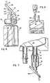
- Figure 3is a vertical sectional view of one embodiment of a vial which may be utilized in accordance with this invention in the connected system of Figure 1.
- Figures 4, 5 and 6are vertical sectional views showing alternative embodiments of vials which may be used as a substitute for the vial of Figure 3.
- Figure 7is detailed, fragmentary elevational view of a bag similar to Figure 1, but using the connector of Figure 6.
- Figure 8is a perspective view showing how the closed system of Figure 1 may be manipulated after opening of the connection between the two containers shown to remove liquid from container 12.
- Figure 1shows a supplemental medication administering system 10 in which a vial 12 is provided in sterile connection with a flexible, collapsible container 14, which may be generally similar in construction to the Mini-Bag sold by Travenol Laboratories, Inc., of Deerfield, Illinois, modified as described herein.
- Vial 12may be similar to conventional dosage ampules except for the modifications described below.
- Vial 12may typically contain a liquid or solid medicament material 16, and may further define a closure 20 for sealingly occluding mouth portion 18.
- Closure 20may further include a latex needle-pierceable stopper 22 ( Figure 3), and may carry in sealed manner a conduit member 24 which includes at its outer end a connection member 26 for providing sealed connection between itself and a corresponding connector member 28, whuch is carried on the end of conduit 30 in sealed relation with collapsible bag 14.
- Connector members 26, 28comprise a transparent housing means with a thermoplastic wall portion 34, positioned as part of the wall of the housing means.
- Connecting means 36are provided for connecting the respective connectors 26, 28 together, with the respective walls 34 being brought together into facing contact.
- One wallis opaque and the other is transparent, as previously described.
- sterile connectionis achieved as previously described by exposing the connected housings to radiant energy such as infrared radiation, so that the wall portions in facing contact can fuse together and open an aperture through the wall portions to provide a sterile connection between the interiors of the respective housings without disconnection thereof.
- radiant energysuch as infrared radiation
- Thisprovides of course a connection between containers 12 and 14, permitting diluent, for example, in bag 14 to flow into contact with the solid, dry material 16 of vial 12.
- the systemmay be agitated by shaking without opening, and then the liquid contents, carrying dissolved or suspended material 16, may be allowed to flow back into bag 14. If the contents 16 are liquid, then can directly flow into bag 14.
- Conduit member 24, carried by connector member 26,may carry a sharpened point or spike 58 at its end so that, after connection and opening between connector members 26, 28 has been made, a further connection between the contents of the vial 16 can be opened by the point 58 penetrating through stopper 22.
- connector member 28amounted on bag 14, may carry a hollow pointed spike member 37, which, in turn, is connected to conduit 30 of bag 14, by means of a flexible, tubular boot member 39.
- conduit 30Positioned within conduit 30 is a tubular member 41 which carries a needle-pierceable diaphragm 43. Accordingly, after the sealed connection has been made between connector member 28a and another connector member on a vial such as vial 12, spike member 37 may be advanced to penetrate diaphragm 43, which is possible because of the presence of flexible boot 39, so that an open channel is formed between the inside of vial 12 and the interior of bag 14.
- spike member 37 and diaphragm 43may be replaced, if desired, by a breakaway projecting member extending outwardly from a closed end of a tubular structure analogous to spike member 37, in a manner similar to that shown in Figure 4.
- conduit 30which may be made of a heat sealable material such as polyvinyl chloride plastic, may be clamped or preferably heat sealed to provide a sealed end 38 to bag 14 (see Figure 2), and the conduit 30 outside of the sealed end may be severed to get rid of vial 12 and the connectors 26, 28.
- the contents of bag 14remain reliably sterile, and may be stored for a period of time which is considerably longer than in the case where a conventional, aseptic connection between containers 12 and 14 has been made.
- an aseptic connectionmay be made through added conventional sealed port 40 in bag 14 by means of supplemental medication set 42, for example, which may be of the type previously described and sold by Travenol Laboratories, Inc.
- Supplemental medication set 42may, in turn, be connected to a Y-site 44 of an appropriate administration set 46 such as the ADD-A-LINE set described above.
- the setmay be connected with a conventional parenteral solution container 48; the set primed; and the set needle 50 may be inserted into the venous system of the patient as shown in Figure 2.
- flexible container 14is generally set at a vertically higher level than container 48. Accordingly, when clamp 54 is opened, the contents of container 14 preferentially flow into set 46, and into the patient's venous system through needle 50, for immediate administration of supplemental medication. When the contents of bag 14 are exhausted, or clamp 54 is closed, the normal flow of liquid from parenteral solution container 48 may be resumed.
- the generally rigid bottle member 54 shown in Figure 3includes, as stated, the puncturable resealable stopper means 22 retained in mouth portion 18 by a ring retention means 56, comprising a crimped metal ring of conventional design.
- Conduit member 24is defined in part by a rigid, tubular cannula which, in turn, defines an inwardly-pointed spike 58 adapted to penetrate puncturable stopper means 22.
- a flexible boot member 60is sealed to the mouth 18 of the vial 12 at one end 62, by clamping action as shown on the part of ring retention means 56. At its other end, boot 60 is sealed to cannula 24 at area 64.
- Boot 60is made of a flexible, elastomeric material so that cannula 24 may be manipulated upwardly and downwardly to cause pointed end 58 to penetrate stopper 22, for communication of cannula 24 with the interior of vial 12 in aseptic manner.
- Body 66 of the vial of Figure 4may be self-supporting in its shape, but sufficiently resilient to be manually collapsible to assist in the expulsion of the contents within body 66. Additionally, the body 66 may have sufficient plastic memory to tend to spring out again into its original shape after manual collapse, if desired, so that the container is capable of exerting gentle suction, for facilitating the filling of body 66 with a diluent or the like.
- a semi-rigid closure member 68is sealed to the open end of cup-like body 66 as shown, and defines a flexible tube 70 which is sealed at its outer end 72 to a conduit member 74.
- the outer end of conduit member 74may be integrally attached to a connector member 26a of similar or identical design to connector member 26 previously described.
- conduit member 74defines a closed end wall 76, sealed within tubing 70, so that its inner end is in communication with the interior of body 66 of the vial of Figure 4. Means for rupturing the closed wall 76 are provided.
- Projecting member 78extends outwardly from closed end wall 76 of conduit member 74.
- Tubing 70, consituting part of the closure of the mouth portion of the vial 66is sufficiently resilient to permit manual bending of projecting member 78 to cause rupture of the end wall 76, to permit the opening of conduit member 74, providing communication between the interior of connector 26a and vial 66.
- a vialcomprising a flexible body 80
- the flexible body 80defines a plurality of bellows-like convolutions 82 so that the vial may be manually collapsed by flexing of the convolutions, and will tend to spring back to its normal configuration, exerting suction for assisting and receiving diluent solution from another container, or the like.
- a closure member 68ais provided, being sealed to the mouth of vial body 80 as shown.
- the remaining parts including conduit 74a, tubing 70a, projecting member 78a and connector member 26a,may be identical in structure and function to the corresponding parts of Figure 4.
- a vial 84which may be a conventional rigid glass vial, for example, may contain a rubber stopper 86 as shown, which carries a vertically upstanding rubber sleeve 88 as an integral part of the stopper.
- Connector member 28adefines a transparent housing 92, having a thermoplastic wall member 94 having a function similar to the previous connector members.
- Bayonet 96 and aperture 98are proportioned to lockingly fit in the corresponding aperture and bayonet of a similar housing, for sterile connection.
- Conduit 100communicates at one end with the chamber 102 which is partially defined by the inner surface of thermoplastic wall member 94. At the other end of conduit 100 an end wall 104 is defined, and a projecting member 106 projecting out from wall 104 and rupturable by bending to open wall 104 in a manner similar to that described with respect to members 78 and 78a in Figures 4 and 5.
- this vialmay be opened, typically after connection of connector member 28a with mating connector member, attached, for example, to a bag similar to bag 14, by laterally bending connector member 28a.
- Connector member 28acan flex laterally because of the presence of sleeve 88, to snap away projecting member 106 by impingement with the inner wall of the vial 84. Projecting member 106 then falls to the bottom of the vial.
- the flexible bag 14may be positioned in the vertical position as shown in Figure 1, and manually squeezed to force some of the liquid contents of the bag 14 through the connection into vial 12.
- bubbles of air or other gas in vial 12which is compressed by the influx of the liquid move upwardly through the connection into bag 14.
- Another squeeze of the bag 14provides more liquid, until the desired amount of liquid is transferred. This technique may be used in the instance where the contents of the vial connected to bag 14 are solid.
- the vial 12(or other embodiment thereof) may then be shaken to dissolve the solid contents.
- the bag and vial systemmay then be inverted to the position as shown in Figure 8.
- bag 14may be squeezed again to force air or other gas in the bag into vial 12.
- the air bubblesrise to the top of the. vial, and upon release of the pressure on bag 14, the compressed air in vial 12 forces some of the liquid 110 in the vial downwardly back into bag 14.
- Repeated application of pressure to bag 14causes more air to pass into vial 12 under pressure, and, upon release, the pressurized air forces more of the liquid out until the vial 12 is empty.
- conduit 30may be heat-sealed and severed as described previously, and bag 14 may be placed into storage for ultimate use.
- the parameters of the closed system shown in Figures 1 and 8therefore preferably meet the following conditions: the air volume (which is intended to include any other gas present) in bag 14 and vial 12 (which is intended to include any design of vial used) must exceed the liquid volume of bag 14, plus the combined total internal volume of conduits 30 and 24, being the entire volume of the connection flow path for fluids between bag 14 and vial 12. Furthermore, the air volume of vial 12 must exceed the combined total internalvolume of conduits 30 and 24, including the internal volumes of connectors 26, 28.
- conduit 24does not include the volume within boot 60 but outside of tubular conduit member 24, since conduit member 24 is positioned in sealed relation within stopper 22.
- a means whereby the sterile contents of a vialmay be brought into contact with a diluent or other ingredient of a formulation which is desirably mixed without a breach of sterility.
- the reliability of sterilityis so high that sensitive materials may be stored for a substantial period of time following the mixing, when such would not be advisable if merely normal aseptic techniques were followed. After such storage, the contents may be administered in any manner desired for any use in or out of the medical field, using one or more of the connected containers as shown herein, or equivalent structures.
- vialsmay be utilized having more than one sterile connector system attached thereto, for connection with a multiplicity of other containers of various types as may be warranted by the situation.
Landscapes
- Health & Medical Sciences (AREA)
- Pharmacology & Pharmacy (AREA)
- Life Sciences & Earth Sciences (AREA)
- Animal Behavior & Ethology (AREA)
- General Health & Medical Sciences (AREA)
- Public Health (AREA)
- Veterinary Medicine (AREA)
- Medical Preparation Storing Or Oral Administration Devices (AREA)
- Materials For Medical Uses (AREA)
- Infusion, Injection, And Reservoir Apparatuses (AREA)
- Closures For Containers (AREA)
Description
- In parenteral solution therapy, supplemental medication is often added to the patient along with the bulk solutions. This may be conveniently done, for example, by means of the ADD-A-LINE and the CONTINUFLO sets for parenteral solution administration sold by Travenol Laboratories, Inc. of Deerfield, Illinois, and described, for example, in US-A-4034754 and US-A-4105029.
- Accordingly, materials such as antibiotic may be administered at the physician's option on an intermittent basis during intravenous solution treatment by means of a connection into the main intravenous solution line communicating with the venous system of the patient, or on a continuous basis by addition to the bulk solution.
- In a large hospital operation, it of course would be desirable to have the supplemental medicament materials ready in their. liquid, diluted form for immediate administration at the option of the physician. However, many of these materials must be stored in the dry form until immediately before use, particularly because of the danger of contamination through bacterial growth, or lack of pharmaceutical stability, which may result when the liquid or dry medicament is mixed or reconstituted by adding a diluent a substantial period of time before its administration.
- One object of this invention relates to a sterile system in which liquid ordry medicament materials or the like may be mixed or reconstituted with a sterile diluent at a convenient time substantially prior to the time of use. The object is to retain a reliable, sterile seal of the system so that multiplication of bacteria in the system is not a problem. As a result of this, fluid or dry medicaments and the like can be mixed or reconstituted with diluent in a hospital pharmacy, for example, at a convenient slack period time, and stored for use at a future date. Then, when the medicament is needed, it is ready in liquid form for immediate use without having to go through the time-consuming effort of reconstituting the material with diluent at the time when it is needed.
- It is known to connect two members to fluid conduits and to each other to provide a sterile connection, in which the two members have adjacent walls which close off the respective conduits to each other, the walls being openable by the application of radiant energy. This principle is described in US-A-4157723.
- US-A-4022256 describes opening an aperture through abutting walls by means of electrical heating to melt the walls. This is a much less convenient procedure than the simple procedure of applying radiant energy as described in US-A-4157723, since a special heating die is required and it is possible, due to material sticking to the die, for the connector to be opened or to be very weak.
- A disadvantage of the radiant-energy technique as described in US-A-4157723 is that each connector housing has to be made with a wall opaque to radiant energy surrounded by a region of the housing transparent to radiant energy. In practice, each housing is made of a transparent material and incorporates an opaque wall of different material. Both the body of the housing and the opaque wall can be made with the same plastics resin, such as polycarbonate, but the opaque wall portion only has to contain an opaque filler, such as carbon black. A further disadvantage is that radiant energy has to be applied to both opaque walls independently through transparent portions of the corresponding housings. On application of radiant energy to each wall, the wall melts and flows, so that an opening is formed between the members to bring them into fluid communication.
- The present invention permits an opening to be formed through two walls in facing contact by application of radiant energy to only one of the two walls.
- In accordance with this invention there is provided a fluid transfer assembly comprising a first member attachable to a conduit and a second member attachable to a conduit, the members being connectible to permit fluid flow from one conduit through the two members to the other conduit, the flow path being blocked by a wall of the first member and a wall of the second member, the two walls being arranged in facing contact when the members are connected, said walls being meltable by absorption of applied radiant energy to open the walls to allow fluid flow through the members characterised in that only the wall of the first member is made of a material which absorbs radiant energy so as to melt the wall, the wall of the second member being made of a material which compared with the material of the wall of the first member is relatively transparent to said radiant energy and is meltable by conduction of heat from the wall of the first member.
- It is generally currently preferred to select a predominantly crystalline plastic material for the meltable walls (e.g. carbon-filled poly(4-methyl-1-pentene) for the wall of the first member). Such materials preferably have a crystalline melting point of above 200°C.
- Accordingly, the fusing and hole-opening step can provide indication that the walls of the newly- formed aperture through the abutting membranes have been exposed to a sterilizing temperature, giving a highly reliable indication of the formation of a sterile connection.
- As the result of this, in use, the diluent can pass through the sterile system to reconstitute the dry medicament with firm reliability that sterility has not been breached, despite the formation of a new connection between the two containers.
- In the drawings, Figure 1 is an elevational view of a supplemental medication administering system, in which a vial and a flexible, collapsible container are linked together in sterile connection, using a transfer assembly according to this invention.
- Figure 2 is an elevational view showing how the flexible collapsible container of Figure 1, after having dissolved and received the dry, solid contents of the vial, may be connected to a supplemental medication administration set positioned in connection with a conventional administration set for parenteral solution.
- Figure 3 is a vertical sectional view of one embodiment of a vial which may be utilized in accordance with this invention in the connected system of Figure 1.
- Figures 4, 5 and 6 are vertical sectional views showing alternative embodiments of vials which may be used as a substitute for the vial of Figure 3.
- Figure 7 is detailed, fragmentary elevational view of a bag similar to Figure 1, but using the connector of Figure 6.
- Figure 8 is a perspective view showing how the closed system of Figure 1 may be manipulated after opening of the connection between the two containers shown to remove liquid from
container 12. - Referring to the drawings, Figure 1 shows a supplemental
medication administering system 10 in which avial 12 is provided in sterile connection with a flexible,collapsible container 14, which may be generally similar in construction to the Mini-Bag sold by Travenol Laboratories, Inc., of Deerfield, Illinois, modified as described herein.Vial 12, on the other hand, may be similar to conventional dosage ampules except for the modifications described below. Vial 12 may typically contain a liquid orsolid medicament material 16, and may further define aclosure 20 for sealingly occludingmouth portion 18. Closure 20 may further include a latex needle-pierceable stopper 22 (Figure 3), and may carry in sealed manner a conduit member 24 which includes at its outer end aconnection member 26 for providing sealed connection between itself and acorresponding connector member 28, whuch is carried on the end ofconduit 30 in sealed relation withcollapsible bag 14.Connector members respective connectors - Accordingly, sterile connection is achieved as previously described by exposing the connected housings to radiant energy such as infrared radiation, so that the wall portions in facing contact can fuse together and open an aperture through the wall portions to provide a sterile connection between the interiors of the respective housings without disconnection thereof. This provides of course a connection between
containers bag 14 to flow into contact with the solid,dry material 16 ofvial 12. The system may be agitated by shaking without opening, and then the liquid contents, carrying dissolved or suspendedmaterial 16, may be allowed to flow back intobag 14. If thecontents 16 are liquid, then can directly flow intobag 14. - Conduit member 24, carried by
connector member 26, may carry a sharpened point orspike 58 at its end so that, after connection and opening betweenconnector members vial 16 can be opened by thepoint 58 penetrating throughstopper 22. - Correspondingly, as shown in Figure 7, connector member 28a, mounted on
bag 14, may carry a hollowpointed spike member 37, which, in turn, is connected toconduit 30 ofbag 14, by means of a flexible,tubular boot member 39. - Positioned within
conduit 30 is a tubular member 41 which carries a needle-pierceable diaphragm 43. Accordingly, after the sealed connection has been made between connector member 28a and another connector member on a vial such asvial 12,spike member 37 may be advanced to penetratediaphragm 43, which is possible because of the presence offlexible boot 39, so that an open channel is formed between the inside ofvial 12 and the interior ofbag 14. - Alternatively,
spike member 37 anddiaphragm 43 may be replaced, if desired, by a breakaway projecting member extending outwardly from a closed end of a tubular structure analogous to spikemember 37, in a manner similar to that shown in Figure 4. - Following this,
conduit 30, which may be made of a heat sealable material such as polyvinyl chloride plastic, may be clamped or preferably heat sealed to provide a sealedend 38 to bag 14 (see Figure 2), and theconduit 30 outside of the sealed end may be severed to get rid ofvial 12 and theconnectors bag 14 remain reliably sterile, and may be stored for a period of time which is considerably longer than in the case where a conventional, aseptic connection betweencontainers - When the time arrives for use of the liquid contents, containing the
material 16 such as a powdered antibiotic, an aseptic connection may be made through added conventional sealed port 40 inbag 14 by means ofsupplemental medication set 42, for example, which may be of the type previously described and sold by Travenol Laboratories, Inc. Supplemental medication set 42 may, in turn, be connected to a Y-site 44 of an appropriate administration set 46 such as the ADD-A-LINE set described above. The set may be connected with a conventionalparenteral solution container 48; the set primed; and theset needle 50 may be inserted into the venous system of the patient as shown in Figure 2. - By this technique, conventional parenteral solution administration may be provided to the patient by appropriate adjustment of
roller clamp 52. - In use;
flexible container 14 is generally set at a vertically higher level thancontainer 48. Accordingly, whenclamp 54 is opened, the contents ofcontainer 14 preferentially flow intoset 46, and into the patient's venous system throughneedle 50, for immediate administration of supplemental medication. When the contents ofbag 14 are exhausted, orclamp 54 is closed, the normal flow of liquid fromparenteral solution container 48 may be resumed. - Turning to the details of
vial 12, the generallyrigid bottle member 54 shown in Figure 3 includes, as stated, the puncturable resealable stopper means 22 retained inmouth portion 18 by a ring retention means 56, comprising a crimped metal ring of conventional design. - Conduit member 24 is defined in part by a rigid, tubular cannula which, in turn, defines an inwardly-
pointed spike 58 adapted to penetrate puncturable stopper means 22. Aflexible boot member 60 is sealed to themouth 18 of thevial 12 at oneend 62, by clamping action as shown on the part of ring retention means 56. At its other end,boot 60 is sealed to cannula 24 atarea 64. Boot 60 is made of a flexible, elastomeric material so that cannula 24 may be manipulated upwardly and downwardly to causepointed end 58 to penetratestopper 22, for communication of cannula 24 with the interior ofvial 12 in aseptic manner.- Turning to Figure 4, another embodiment of the vial is disclosed.
Body 66 of the vial of Figure 4 may be self-supporting in its shape, but sufficiently resilient to be manually collapsible to assist in the expulsion of the contents withinbody 66. Additionally, thebody 66 may have sufficient plastic memory to tend to spring out again into its original shape after manual collapse, if desired, so that the container is capable of exerting gentle suction, for facilitating the filling ofbody 66 with a diluent or the like. - A
semi-rigid closure member 68 is sealed to the open end of cup-like body 66 as shown, and defines a flexible tube 70 which is sealed at its outer end 72 to a conduit member 74. The outer end of conduit member 74 may be integrally attached to a connector member 26a of similar or identical design toconnector member 26 previously described. - At its other end from the connector member 26a, conduit member 74 defines a
closed end wall 76, sealed within tubing 70, so that its inner end is in communication with the interior ofbody 66 of the vial of Figure 4. Means for rupturing theclosed wall 76 are provided. - Projecting
member 78 extends outwardly fromclosed end wall 76 of conduit member 74. Tubing 70, consituting part of the closure of the mouth portion of thevial 66 is sufficiently resilient to permit manual bending of projectingmember 78 to cause rupture of theend wall 76, to permit the opening of conduit member 74, providing communication between the interior of connector 26a andvial 66. - Turning to Figure 5, a vial comprising a
flexible body 80 is disclosed, in which theflexible body 80 defines a plurality of bellows-likeconvolutions 82 so that the vial may be manually collapsed by flexing of the convolutions, and will tend to spring back to its normal configuration, exerting suction for assisting and receiving diluent solution from another container, or the like. - As in the embodiment of Figure 4, a closure member 68a is provided, being sealed to the mouth of
vial body 80 as shown. The remaining parts including conduit 74a, tubing 70a, projecting member 78a and connector member 26a, may be identical in structure and function to the corresponding parts of Figure 4. - Referring to Figure 6, a
vial 84, which may be a conventional rigid glass vial, for example, may contain arubber stopper 86 as shown, which carries a verticallyupstanding rubber sleeve 88 as an integral part of the stopper. Connector member 28a defines atransparent housing 92, having athermoplastic wall member 94 having a function similar to the previous connector members.Bayonet 96 andaperture 98 are proportioned to lockingly fit in the corresponding aperture and bayonet of a similar housing, for sterile connection. Conduit 100 communicates at one end with thechamber 102 which is partially defined by the inner surface ofthermoplastic wall member 94. At the other end ofconduit 100 anend wall 104 is defined, and a projectingmember 106 projecting out fromwall 104 and rupturable by bending to openwall 104 in a manner similar to that described with respect tomembers 78 and 78a in Figures 4 and 5.- Accordingly, this vial may be opened, typically after connection of connector member 28a with mating connector member, attached, for example, to a bag similar to
bag 14, by laterally bending connector member 28a. Connector member 28a can flex laterally because of the presence ofsleeve 88, to snap away projectingmember 106 by impingement with the inner wall of thevial 84. Projectingmember 106 then falls to the bottom of the vial. - After opening of all of the connections between the vial (such as
vial 12 or any of the other vials shown) andbag 14, for example, theflexible bag 14 may be positioned in the vertical position as shown in Figure 1, and manually squeezed to force some of the liquid contents of thebag 14 through the connection intovial 12. Upon release of manual squeezing, bubbles of air or other gas invial 12 which is compressed by the influx of the liquid move upwardly through the connection intobag 14. Another squeeze of thebag 14 provides more liquid, until the desired amount of liquid is transferred. This technique may be used in the instance where the contents of the vial connected tobag 14 are solid. - The vial 12 (or other embodiment thereof) may then be shaken to dissolve the solid contents. The bag and vial system may then be inverted to the position as shown in Figure 8. In the event that the liquid contents of the vial do not readily flow into
bag 14 in a spontaneous manner,bag 14 may be squeezed again to force air or other gas in the bag intovial 12. The air bubbles rise to the top of the. vial, and upon release of the pressure onbag 14, the compressed air invial 12 forces some of the liquid 110 in the vial downwardly back intobag 14. Repeated application of pressure to bag 14 causes more air to pass intovial 12 under pressure, and, upon release, the pressurized air forces more of the liquid out until thevial 12 is empty. - Thereafter,
conduit 30 may be heat-sealed and severed as described previously, andbag 14 may be placed into storage for ultimate use. - The above technique for transferring liquid to and from the bag and the vial requires certain dimensional characteristics of the double container system, or the solid and liquid contents will not be completely removable from the
vial 12 in the closed system. - The parameters of the closed system shown in Figures 1 and 8 therefore preferably meet the following conditions: the air volume (which is intended to include any other gas present) in
bag 14 and vial 12 (which is intended to include any design of vial used) must exceed the liquid volume ofbag 14, plus the combined total internal volume ofconduits 30 and 24, being the entire volume of the connection flow path for fluids betweenbag 14 andvial 12. Furthermore, the air volume ofvial 12 must exceed the combined total internalvolume ofconduits 30 and 24, including the internal volumes ofconnectors - It is to be understood, of course, that in the specific instance of Figure 3, the volume of conduit 24 does not include the volume within
boot 60 but outside of tubular conduit member 24, since conduit member 24 is positioned in sealed relation withinstopper 22. - Under the above conditions, when one of the containers such as
bag 14 is compressible and the other of the containers such asvial 12 is non- expansible, the above conditions provide a joined container system in which the contents of non-expansible container 12 can be completely removed by, in effect, pumping liquid out ofcontainer 12, or fromcontainer 14 intocontainer 12 and then back out again. - Accordingly, there is provided a means whereby the sterile contents of a vial may be brought into contact with a diluent or other ingredient of a formulation which is desirably mixed without a breach of sterility. The reliability of sterility is so high that sensitive materials may be stored for a substantial period of time following the mixing, when such would not be advisable if merely normal aseptic techniques were followed. After such storage, the contents may be administered in any manner desired for any use in or out of the medical field, using one or more of the connected containers as shown herein, or equivalent structures.
- It is also contemplated that vials may be utilized having more than one sterile connector system attached thereto, for connection with a multiplicity of other containers of various types as may be warranted by the situation.
Claims (4)
Applications Claiming Priority (2)
| Application Number | Priority Date | Filing Date | Title |
|---|---|---|---|
| US9168879A | 1979-11-05 | 1979-11-05 | |
| US91688 | 1979-11-05 |
Related Parent Applications (2)
| Application Number | Title | Priority Date | Filing Date |
|---|---|---|---|
| EP19810900028DivisionEP0041071A4 (en) | 1979-11-05 | 1980-10-09 | System for the sterile mixing of materials. |
| EP81900028.2Division | 1980-10-09 |
Publications (3)
| Publication Number | Publication Date |
|---|---|
| EP0079326A2 EP0079326A2 (en) | 1983-05-18 |
| EP0079326A3 EP0079326A3 (en) | 1984-05-02 |
| EP0079326B1true EP0079326B1 (en) | 1987-02-04 |
Family
ID=22229146
Family Applications (3)
| Application Number | Title | Priority Date | Filing Date |
|---|---|---|---|
| EP19830200010WithdrawnEP0079327A3 (en) | 1979-11-05 | 1980-10-09 | Fluid transfer assembly |
| EP19830200009ExpiredEP0079326B1 (en) | 1979-11-05 | 1980-10-09 | Fluid transfer assembly |
| EP19810900028WithdrawnEP0041071A4 (en) | 1979-11-05 | 1980-10-09 | System for the sterile mixing of materials. |
Family Applications Before (1)
| Application Number | Title | Priority Date | Filing Date |
|---|---|---|---|
| EP19830200010WithdrawnEP0079327A3 (en) | 1979-11-05 | 1980-10-09 | Fluid transfer assembly |
Family Applications After (1)
| Application Number | Title | Priority Date | Filing Date |
|---|---|---|---|
| EP19810900028WithdrawnEP0041071A4 (en) | 1979-11-05 | 1980-10-09 | System for the sterile mixing of materials. |
Country Status (12)
| Country | Link |
|---|---|
| US (1) | US4434822A (en) |
| EP (3) | EP0079327A3 (en) |
| JP (1) | JPH0211257B2 (en) |
| BE (1) | BE885878A (en) |
| BR (1) | BR8008904A (en) |
| CA (1) | CA1171030A (en) |
| DK (1) | DK290281A (en) |
| ES (1) | ES496552A0 (en) |
| IL (1) | IL61252A (en) |
| NO (1) | NO812270L (en) |
| WO (1) | WO1981001241A1 (en) |
| ZA (1) | ZA806287B (en) |
Cited By (1)
| Publication number | Priority date | Publication date | Assignee | Title |
|---|---|---|---|---|
| DE102005056488A1 (en)* | 2005-11-21 | 2007-05-24 | Ing. Erich Pfeiffer Gmbh | Dispenser and dosing unit for medium dosing |
Families Citing this family (57)
| Publication number | Priority date | Publication date | Assignee | Title |
|---|---|---|---|---|
| ES274987Y (en)* | 1981-01-19 | 1985-04-01 | Baxter Travenol Laboratories, Inc. | PERFECTED STERILE CONNECTOR DEVICE. |
| US4465471A (en)* | 1981-08-26 | 1984-08-14 | Eli Lilly And Company | Intravenous administration system for dry medicine |
| US4484920A (en)* | 1982-04-06 | 1984-11-27 | Baxter Travenol Laboratories, Inc. | Container for mixing a liquid and a solid |
| US4458733A (en)* | 1982-04-06 | 1984-07-10 | Baxter Travenol Laboratories, Inc. | Mixing apparatus |
| US4534758A (en)* | 1983-07-15 | 1985-08-13 | Eli Lilly & Company | Controlled release infusion system |
| US4828557A (en)* | 1984-04-06 | 1989-05-09 | Persidsky Maxim D | Sterile connector and method |
| US4902287A (en)* | 1987-09-24 | 1990-02-20 | Miles Inc. | Sterilizable system for blood storage |
| JPS6485653A (en)* | 1987-09-28 | 1989-03-30 | Terumo Corp | Drug receiving container |
| US5964785A (en)* | 1988-01-25 | 1999-10-12 | Baxter International Inc. | Bayonet look cannula for pre-slit y-site |
| US5100394A (en)* | 1988-01-25 | 1992-03-31 | Baxter International Inc. | Pre-slit injection site |
| EP0544653B1 (en) | 1988-01-25 | 1996-06-05 | Baxter International Inc. | Injection site |
| CA1330412C (en) | 1988-07-08 | 1994-06-28 | Steven C. Jepson | Pre-slit injection site and tapered cannula |
| IE62767B1 (en) | 1989-03-17 | 1995-02-22 | Baxter Int | Pre-slit injection site and tapered cannula |
| JPH0351055A (en)* | 1989-07-19 | 1991-03-05 | Sekisui Chem Co Ltd | Chemical solving/delivering system and solution container used therefor |
| US5304163A (en)* | 1990-01-29 | 1994-04-19 | Baxter International Inc. | Integral reconstitution device |
| US5776125A (en)* | 1991-07-30 | 1998-07-07 | Baxter International Inc. | Needleless vial access device |
| US5858016A (en)* | 1992-07-14 | 1999-01-12 | Baxter International Inc. | Sterile/aseptic connector |
| US5300034A (en)* | 1992-07-29 | 1994-04-05 | Minnesota Mining And Manufacturing Company | Iv injection site for the reception of a blunt cannula |
| US5351383A (en)* | 1992-07-29 | 1994-10-04 | Minnesota Mining And Manufacturing Company | Method of making an injection or sampling site |
| US5385547A (en)* | 1992-11-19 | 1995-01-31 | Baxter International Inc. | Adaptor for drug delivery |
| US5827219A (en)* | 1993-10-28 | 1998-10-27 | Medrad, Inc. | Injection system and pumping system for use therein |
| DE69432582T2 (en)* | 1993-10-28 | 2003-11-27 | Medrad, Inc. | System for the administration of liquids in several patients |
| US5569181A (en)* | 1993-10-28 | 1996-10-29 | Medrad, Inc. | Sterility assurance for contrast delivery system |
| DE1258262T1 (en)* | 1993-10-28 | 2003-04-10 | Medrad, Inc. | Contrast delivery system |
| EP0692766B1 (en)* | 1994-07-12 | 2002-05-08 | Medrad, Inc. | Closed loop information path for medical fluid delivery systems |
| US5840026A (en)* | 1994-09-21 | 1998-11-24 | Medrad, Inc. | Patient specific dosing contrast delivery systems and methods |
| GB9503068D0 (en)* | 1995-02-16 | 1995-04-05 | Kodak Ltd | Photographic processing chemicals |
| US6162206A (en)* | 1997-12-23 | 2000-12-19 | Baxter International Inc. | Resealable access site |
| US6616626B2 (en)* | 2000-12-21 | 2003-09-09 | Scimed Life Systems, Inc. | Infusion devices and method |
| US7109974B2 (en)* | 2002-03-05 | 2006-09-19 | Matsushita Electric Industrial Co., Ltd. | Remote control system including an on-screen display (OSD) |
| EP1812101A4 (en) | 2004-11-16 | 2014-04-23 | Medrad Inc | Modeling of pharmaceutical propagation |
| HUE034171T2 (en) | 2004-11-24 | 2018-02-28 | Bayer Healthcare Llc | Devices, systems and methods for fluid delivery |
| EP3376504A1 (en)* | 2006-12-29 | 2018-09-19 | Bayer Healthcare, LLC | Patient-based parameter generation systems for medical injection procedures |
| US7938454B2 (en)* | 2007-04-24 | 2011-05-10 | Hyclone Laboratories, Inc. | Sterile connector systems |
| CA2682650A1 (en)* | 2007-04-24 | 2008-10-30 | Hyclone Laboratories, Inc. | Sterile connector systems |
| US8428694B2 (en) | 2007-07-17 | 2013-04-23 | Medrad, Inc. | Methods for determination of parameters for a procedure, for estimation of cardiopulmonary function and for fluid delivery |
| US9421330B2 (en)* | 2008-11-03 | 2016-08-23 | Bayer Healthcare Llc | Mitigation of contrast-induced nephropathy |
| AU2011270772C1 (en) | 2010-06-24 | 2017-04-20 | Bayer Healthcare Llc | Modeling of pharmaceutical propagation and parameter generation for injection protocols |
| US8448992B2 (en)* | 2011-02-16 | 2013-05-28 | Fenwal, Inc. | Sterile docking device, medical fluid flow system with sterile docking device and method of using same |
| JP2014527881A (en) | 2011-09-21 | 2014-10-23 | ベイヤー メディカル ケア インク. | Continuous multi-fluid pump device, drive and actuation system and method |
| DK2850418T3 (en) | 2012-05-14 | 2019-05-20 | Bayer Healthcare Llc | SYSTEMS AND PROCEDURES FOR DETERMINING PROTOCOLS FOR PHARMACEUTICAL LIQUID INJECTION BASED ON X-ray tube tension |
| US9555379B2 (en) | 2013-03-13 | 2017-01-31 | Bayer Healthcare Llc | Fluid path set with turbulent mixing chamber, backflow compensator |
| US9839582B2 (en) | 2014-12-02 | 2017-12-12 | Fenwal, Inc. | Sterile connection syringe assemblies |
| US10507319B2 (en) | 2015-01-09 | 2019-12-17 | Bayer Healthcare Llc | Multiple fluid delivery system with multi-use disposable set and features thereof |
| US10898638B2 (en) | 2016-03-03 | 2021-01-26 | Bayer Healthcare Llc | System and method for improved fluid delivery in multi-fluid injector systems |
| US12263326B2 (en) | 2016-11-14 | 2025-04-01 | Bayer Healthcare Llc | Methods and systems for verifying the contents of a syringe used for medical fluid delivery |
| US20200222281A1 (en)* | 2017-07-17 | 2020-07-16 | Baxter International Inc. | Sterile Product Bag with Filtered Port |
| WO2019046261A1 (en) | 2017-08-31 | 2019-03-07 | Bayer Healthcare Llc | System and method for drive member position and fluid injector system mechanical calibration |
| EP3676854A1 (en) | 2017-08-31 | 2020-07-08 | Bayer Healthcare LLC | Fluid path impedance assessment for improving fluid delivery performance |
| AU2018326386B2 (en) | 2017-08-31 | 2024-03-28 | Bayer Healthcare Llc | Fluid injector system volume compensation system and method |
| JP7493337B2 (en) | 2017-08-31 | 2024-05-31 | バイエル・ヘルスケア・エルエルシー | Method for dynamic pressure control in a fluid injector system - Patents.com |
| EP3675931B1 (en) | 2017-08-31 | 2021-08-11 | Bayer Healthcare LLC | Injector pressure calibration system and method |
| EP3781233B1 (en) | 2018-04-19 | 2025-09-17 | Bayer Healthcare LLC | System and method for air detection in fluid injector |
| CA3111209A1 (en) | 2018-08-28 | 2020-03-05 | Bayer Healthcare Llc | Fluid injector system with improved ratio performance |
| JP7450608B2 (en) | 2018-08-28 | 2024-03-15 | バイエル・ヘルスケア・エルエルシー | Fluid injector system, method for preventing fluid backflow, and computer program product |
| KR20240090380A (en)* | 2021-10-14 | 2024-06-21 | 엔테그리스, 아이엔씨. | Integrated aseptic system and method of manufacturing the same |
| CN114920403B (en)* | 2022-05-24 | 2023-04-07 | 余江县宏鑫特种水产养殖有限公司 | Water quality improving device for aquaculture |
Family Cites Families (56)
| Publication number | Priority date | Publication date | Assignee | Title |
|---|---|---|---|---|
| US1928998A (en)* | 1930-02-12 | 1933-10-03 | Kovacs Nikolaus | Double ampule for sterile solutions |
| US1921809A (en) | 1931-11-06 | 1933-08-08 | Crain Earl | Gas pipe stop |
| US2342215A (en)* | 1942-08-03 | 1944-02-22 | Harold N Perelson | Dispensing and sealing stopper |
| US2622053A (en) | 1945-12-04 | 1952-12-16 | Henry W Clowe | Method of joining surfaces of heat-fusible materials |
| US2553259A (en) | 1946-09-02 | 1951-05-15 | Nordisk Insulinlab | Process of joining plastic substances |
| US2668364A (en) | 1950-10-27 | 1954-02-09 | Dry Freeze Corp | Drying of materials by infrared radiation |
| US2726656A (en)* | 1952-10-21 | 1955-12-13 | Compule Corp | Hypodermic syringe structure |
| US2839788A (en) | 1953-04-24 | 1958-06-24 | Dembiak Matthew | Method of making hollow plastic or rubber articles |
| US2782495A (en) | 1953-10-14 | 1957-02-26 | Gen Motors Corp | Joining of metals |
| US2894510A (en)* | 1954-02-25 | 1959-07-14 | Fenwal Lab Inc | Sealing closures for fluid containers |
| US2744432A (en) | 1954-07-27 | 1956-05-08 | Sherman Klove Company | Reversible ratchet wrench |
| US2767744A (en)* | 1954-12-27 | 1956-10-23 | Beerman Jack | Liquid transfer device |
| BE548456A (en)* | 1955-09-23 | 1956-06-30 | ||
| US2903004A (en) | 1955-11-01 | 1959-09-08 | Carrier Corp | Coupling devices |
| GB801162A (en) | 1955-11-01 | 1958-09-10 | Carrier Engineering Co Ltd | Improvements in or relating to coupling elements and devices for fluid-flow conduits |
| US2910083A (en) | 1958-01-10 | 1959-10-27 | C W Fuelling Inc | Method and apparatus for terminating and extending fluid transmission mains |
| US3416528A (en)* | 1959-08-17 | 1968-12-17 | Cutter Lab | Blood handling equipment |
| US3214502A (en) | 1960-08-08 | 1965-10-26 | Kendall & Co | Method and apparatus for making adhesive tapes |
| US3023762A (en) | 1960-08-30 | 1962-03-06 | Charles W Fuelling Inc | Gas main terminal fixture |
| US3186450A (en)* | 1962-06-01 | 1965-06-01 | Abbott Lab | Dispensing assembly |
| US3244412A (en) | 1962-10-18 | 1966-04-05 | Northwestern Steel & Wire Comp | Apparatus for melting meltable materials |
| CH402286A (en)* | 1963-05-17 | 1965-11-15 | Hera Ag | Infusion device |
| GB1027528A (en) | 1964-01-28 | 1966-04-27 | Kugler Emanuel | Improvements in the heat sealing and severing of materials |
| US3410979A (en) | 1964-05-28 | 1968-11-12 | Burroughs Corp | Method and apparatus for drilling holes by means of a focused laser beam |
| US3404051A (en) | 1965-03-09 | 1968-10-01 | Morey Paper Mill Supply Co | Method of splicing thermoplastic rope ends by flame treatment |
| US3384526A (en) | 1965-09-02 | 1968-05-21 | Research Inc | Method and machine for joining plastics |
| US3493002A (en) | 1967-12-11 | 1970-02-03 | Chrysler Corp | Coupling apparatus |
| US3549451A (en) | 1968-03-06 | 1970-12-22 | Emanuel Kugler | Method of manufacturing satchel bottom bags |
| CA864509A (en) | 1969-05-21 | 1971-02-23 | K. Rowley Edward | Sealing plastic film |
| US3588440A (en) | 1969-06-26 | 1971-06-28 | Hughes Aircraft Co | Laser combination energy system |
| US3616024A (en) | 1969-07-14 | 1971-10-26 | Phillips Petroleum Co | Method and apparatus for welding heat sealable pipes |
| FR2098873A5 (en)* | 1970-07-30 | 1972-03-10 | Labaz Laboratoires | |
| US3732981A (en)* | 1970-09-01 | 1973-05-15 | Bio Rad Laboratories | Filtration column |
| US3768697A (en)* | 1971-04-20 | 1973-10-30 | Braun Co W | Multi-product dispenser package |
| US3788369A (en)* | 1971-06-02 | 1974-01-29 | Upjohn Co | Apparatus for transferring liquid between a container and a flexible bag |
| US3874384A (en)* | 1971-11-01 | 1975-04-01 | American Hospital Supply Corp | Improved blood storage unit and method of storing blood |
| US3826261A (en)* | 1971-12-27 | 1974-07-30 | Upjohn Co | Vial and syringe assembly |
| US3828779A (en)* | 1972-12-13 | 1974-08-13 | Ims Ltd | Flex-o-jet |
| US4030494A (en) | 1973-11-05 | 1977-06-21 | Francis Tenczar | Fluid connectors |
| US4022205A (en) | 1973-11-05 | 1977-05-10 | Tenczar Francis J | Fluid connectors |
| AR205565A1 (en)* | 1974-04-29 | 1976-05-14 | Abbott Lab | STORAGE AND TRANSFER UNIT FOR AN ADDITIVE PARTICULARLY APPLICABLE TO TRANSFER OF MEDICINES |
| US3968195A (en) | 1974-06-17 | 1976-07-06 | Marilyn Bishop | Method for making sterile connections |
| US3913348A (en) | 1974-07-22 | 1975-10-21 | Gen Electric | Refrigerant system connecting apparatus |
| US3938518A (en)* | 1975-01-15 | 1976-02-17 | Astra Pharmaceutical Products Inc. | Syringe attachment device |
| US3991912A (en)* | 1975-01-23 | 1976-11-16 | Ricardo Hurtado Soto | Flexible package with counter-pressure dispenser |
| US4022256A (en)* | 1975-08-06 | 1977-05-10 | California Institute Of Technology | Aseptic fluid transfer system |
| US3997385A (en) | 1975-08-18 | 1976-12-14 | W. R. Grace & Co. | Clamping of film-like material for radiant energy welding |
| JPS52143755A (en) | 1976-05-26 | 1977-11-30 | Hitachi Ltd | Laser, zone melting device |
| DE2653993C3 (en)* | 1976-11-27 | 1980-05-14 | Stella-Kg Werner Deussen, 6229 Walluf | Container with breakable closure |
| US4105484A (en) | 1977-05-16 | 1978-08-08 | Phillips Petroleum Company | Infrared apparatus for producing a fused fabric |
| US4181140A (en)* | 1978-02-10 | 1980-01-01 | Baxter Travenol Laboratories, Inc. | Frangible resealable closure for a flexible tube having hold open means |
| US4157723A (en)* | 1977-10-19 | 1979-06-12 | Baxter Travenol Laboratories, Inc. | Method of forming a connection between two sealed conduits using radiant energy |
| US4169475A (en)* | 1977-12-08 | 1979-10-02 | Abbott Laboratories | Additive transfer unit |
| US4203443A (en)* | 1977-12-08 | 1980-05-20 | Abbott Laboratories | Additive transfer unit with interlocking means |
| US4265280A (en) | 1979-01-23 | 1981-05-05 | Baxter Travenol Laboratories, Inc. | Connector member for sealed conduits |
| US4325417A (en) | 1979-04-06 | 1982-04-20 | Baxter Travenol Laboratories, Inc. | Connector member for sealed conduits utilizing crystalline plastic barrier membrane |
- 1980
- 1980-10-07CACA000361983Apatent/CA1171030A/ennot_activeExpired
- 1980-10-09BRBR8008904Apatent/BR8008904A/enunknown
- 1980-10-09EPEP19830200010patent/EP0079327A3/ennot_activeWithdrawn
- 1980-10-09EPEP19830200009patent/EP0079326B1/ennot_activeExpired
- 1980-10-09WOPCT/US1980/001336patent/WO1981001241A1/ennot_activeApplication Discontinuation
- 1980-10-09JPJP50021280Apatent/JPH0211257B2/janot_activeExpired - Lifetime
- 1980-10-09EPEP19810900028patent/EP0041071A4/ennot_activeWithdrawn
- 1980-10-10ILIL6125280Apatent/IL61252A/enunknown
- 1980-10-13ZAZA00806287Apatent/ZA806287B/enunknown
- 1980-10-24BEBE0/202594Apatent/BE885878A/ennot_activeIP Right Cessation
- 1980-11-04ESES496552Apatent/ES496552A0/enactiveGranted
- 1981
- 1981-06-30DKDK290281Apatent/DK290281A/enunknown
- 1981-07-03NONO812270Apatent/NO812270L/enunknown
- 1981-10-27USUS06/315,399patent/US4434822A/ennot_activeExpired - Lifetime
Cited By (1)
| Publication number | Priority date | Publication date | Assignee | Title |
|---|---|---|---|---|
| DE102005056488A1 (en)* | 2005-11-21 | 2007-05-24 | Ing. Erich Pfeiffer Gmbh | Dispenser and dosing unit for medium dosing |
Also Published As
| Publication number | Publication date |
|---|---|
| EP0041071A1 (en) | 1981-12-09 |
| BE885878A (en) | 1981-02-16 |
| IL61252A (en) | 1984-02-29 |
| WO1981001241A1 (en) | 1981-05-14 |
| ES8204596A1 (en) | 1982-05-01 |
| ZA806287B (en) | 1981-10-28 |
| JPH0211257B2 (en) | 1990-03-13 |
| EP0079326A2 (en) | 1983-05-18 |
| EP0079327A3 (en) | 1984-04-25 |
| US4434822A (en) | 1984-03-06 |
| CA1171030A (en) | 1984-07-17 |
| NO812270L (en) | 1981-07-03 |
| IL61252A0 (en) | 1980-12-31 |
| BR8008904A (en) | 1981-08-25 |
| EP0079326A3 (en) | 1984-05-02 |
| JPS57500412A (en) | 1982-03-11 |
| DK290281A (en) | 1981-06-30 |
| EP0079327A2 (en) | 1983-05-18 |
| EP0041071A4 (en) | 1983-03-07 |
| ES496552A0 (en) | 1982-05-01 |
Similar Documents
| Publication | Publication Date | Title |
|---|---|---|
| EP0079326B1 (en) | Fluid transfer assembly | |
| EP0172836B1 (en) | Closed drug delivery system | |
| EP0554988B1 (en) | Mixing apparatus | |
| US4392851A (en) | In-line transfer unit | |
| EP0091311B1 (en) | Sterile coupling and method of making same | |
| US4410321A (en) | Closed drug delivery system | |
| EP0104232B1 (en) | Container for mixing a liquid and a solid | |
| EP0442406B1 (en) | Filled and sealed, self-contained mixing container | |
| US5257986A (en) | Container for the separate sterile storage of at least two substances and for mixing said substances | |
| US4368729A (en) | Aseptic system for total parenteral nutrition and the like | |
| US4392850A (en) | In-line transfer unit | |
| GB2117733A (en) | Sterilized liquid mixing system | |
| AU6577280A (en) | System for the sterile mixing of materials | |
| JPH0373307B2 (en) | ||
| JPH05245185A (en) | Aseptic preparation method and device for intravenously administered drug solution | |
| JPH11267181A (en) | Chemical container meltable on use | |
| JPH11198974A (en) | Liquid medicine container for preparing medicine when needed |
Legal Events
| Date | Code | Title | Description |
|---|---|---|---|
| PUAI | Public reference made under article 153(3) epc to a published international application that has entered the european phase | Free format text:ORIGINAL CODE: 0009012 | |
| 17P | Request for examination filed | Effective date:19830119 | |
| AC | Divisional application: reference to earlier application | Ref document number:41071 Country of ref document:EP | |
| AK | Designated contracting states | Designated state(s):CH DE FR GB LI NL SE | |
| PUAL | Search report despatched | Free format text:ORIGINAL CODE: 0009013 | |
| AK | Designated contracting states | Designated state(s):CH DE FR GB LI NL SE | |
| GRAA | (expected) grant | Free format text:ORIGINAL CODE: 0009210 | |
| AC | Divisional application: reference to earlier application | Ref document number:41071 Country of ref document:EP | |
| AK | Designated contracting states | Kind code of ref document:B1 Designated state(s):CH DE FR GB LI NL SE | |
| REF | Corresponds to: | Ref document number:3071903 Country of ref document:DE Date of ref document:19870312 | |
| ET | Fr: translation filed | ||
| PG25 | Lapsed in a contracting state [announced via postgrant information from national office to epo] | Ref country code:SE Effective date:19871010 | |
| PG25 | Lapsed in a contracting state [announced via postgrant information from national office to epo] | Ref country code:LI Effective date:19871031 Ref country code:CH Effective date:19871031 | |
| PLBE | No opposition filed within time limit | Free format text:ORIGINAL CODE: 0009261 | |
| 26N | No opposition filed | ||
| PG25 | Lapsed in a contracting state [announced via postgrant information from national office to epo] | Ref country code:NL Effective date:19880501 | |
| NLV4 | Nl: lapsed or anulled due to non-payment of the annual fee | ||
| REG | Reference to a national code | Ref country code:CH Ref legal event code:PL | |
| REG | Reference to a national code | Ref country code:FR Ref legal event code:CD | |
| PGFP | Annual fee paid to national office [announced via postgrant information from national office to epo] | Ref country code:FR Payment date:19900922 Year of fee payment:11 | |
| PGFP | Annual fee paid to national office [announced via postgrant information from national office to epo] | Ref country code:GB Payment date:19900925 Year of fee payment:11 | |
| PGFP | Annual fee paid to national office [announced via postgrant information from national office to epo] | Ref country code:DE Payment date:19901228 Year of fee payment:11 | |
| PG25 | Lapsed in a contracting state [announced via postgrant information from national office to epo] | Ref country code:GB Effective date:19911009 | |
| GBPC | Gb: european patent ceased through non-payment of renewal fee | ||
| PG25 | Lapsed in a contracting state [announced via postgrant information from national office to epo] | Ref country code:FR Effective date:19920630 | |
| PG25 | Lapsed in a contracting state [announced via postgrant information from national office to epo] | Ref country code:DE Effective date:19920701 | |
| REG | Reference to a national code | Ref country code:FR Ref legal event code:ST | |
| EUG | Se: european patent has lapsed | Ref document number:83200009.5 Effective date:19880712 |