EP0079068A2 - Trailer for motor vehicles - Google Patents
Trailer for motor vehiclesDownload PDFInfo
- Publication number
- EP0079068A2 EP0079068A2EP82110261AEP82110261AEP0079068A2EP 0079068 A2EP0079068 A2EP 0079068A2EP 82110261 AEP82110261 AEP 82110261AEP 82110261 AEP82110261 AEP 82110261AEP 0079068 A2EP0079068 A2EP 0079068A2
- Authority
- EP
- European Patent Office
- Prior art keywords
- frame
- plate
- profile
- leg
- angled
- Prior art date
- Legal status (The legal status is an assumption and is not a legal conclusion. Google has not performed a legal analysis and makes no representation as to the accuracy of the status listed.)
- Granted
Links
Images

Classifications
- B—PERFORMING OPERATIONS; TRANSPORTING
- B62—LAND VEHICLES FOR TRAVELLING OTHERWISE THAN ON RAILS
- B62D—MOTOR VEHICLES; TRAILERS
- B62D63/00—Motor vehicles or trailers not otherwise provided for
- B62D63/06—Trailers
- B—PERFORMING OPERATIONS; TRANSPORTING
- B62—LAND VEHICLES FOR TRAVELLING OTHERWISE THAN ON RAILS
- B62D—MOTOR VEHICLES; TRAILERS
- B62D63/00—Motor vehicles or trailers not otherwise provided for
- B62D63/06—Trailers
- B62D63/062—Trailers with one axle or two wheels
- B62D63/064—Trailers with one axle or two wheels light luggage or equipment trailers, e.g. for batteries, gas generators, gas bottles, stretchers
Definitions
- the inventionrelates to a single or tandem axle trailer for motor vehicles with a structure consisting of a platform which is delimited by side walls which consist of plates surrounded by metal profile frames.
- the inventionhas set itself the task of avoiding the disadvantages mentioned and other disadvantages of known trailer structures and creating a trailer for motor vehicles, the individual parts of which can also be standardized to a certain extent, which are therefore interchangeable and also allow different types of structures perform the same individual elements.
- a trailer of the generic typeis characterized in that the profile of the frame has two mutually parallel legs for resting on the outer and inner surface of the plate, and a central part angled from one leg, which abuts against the edge of the plate and on one side this edge protrudes by an amount which corresponds to at least about half the plate thickness and, angled towards the plate, runs out into the other leg.
- the angling of the middle part of the profile of the framecan be formed at right angles and directed against the plate with a further right-angled bend, directly in front of the plane of the plate with a right-angled bend outwards into the leg.
- the angling of the central part of the profile of the framecan also be formed at an acute angle and immediately before the plane of the Pass the plate into the leg with a correspondingly obtuse angle to the outside.
- the type of configuration of the profiles described aboveensures that these profiles have a substantially higher strength and that the plates surrounded by the profiles can therefore be significantly thinner, because. they are considerably relieved of forces.
- Such thinner platescan also advantageously be designed such that they are significantly more resistant to other influences, such as moisture, wetness, temperatures and the like.
- the formation of the frame profilesresults in the further advantage that the surfaces of the plates are much better protected against mechanical influences, particularly in traffic, by the frame edges projecting outwards, and that these frame edges can also be used to produce special connections.
- the metal profile frameis mitered and angled on its legs, corresponding to the corners of the panel to be framed.
- the frame profileis preferably finished on a long side of the plate at a distance from the corners and a straight profile piece is inserted between these ends.
- the ends of the angled frame part surrounding the platecan lie at the point of the plate where they are covered by half of a screwed or riveted fitting, the other half of the fitting covering the ends of the straight profile piece used.
- the framecan consist of two parts, the ends of which abut each other on two opposite side edges of the plate.
- the framecan also consist of one part and abut one another with its two ends in the course of a side edge of the plate.
- the frame of only a few or a partis composed so that not only the production much easier and cheaper, but also that the power flow is ensured within the individual pieces of the frame.
- the joints of the ends of the frameare preferably designed and arranged in such a way that fittings are attached there, such as hinges, locking hooks or the like. . cover half of the two abutting frame ends with fastening tabs and their fastening means in the form of screws, rivets or the like are passed through the limbs of the fitting resting on the plate. Fittings and / or connecting means are by means of screws, rivets or the like. attached to the frame, which are passed through holes which are arranged in the part of the frame profile which extends beyond the plate edge and extends parallel to the plate plane. With this arrangement, too, a substantial improvement in the general strength is achieved, because without additional measures, the unavoidable frame joints are connected to one another in such a way that, for example, fitting parts are used, so that there is a metallic connection between the frame joints.
- connecting screws with their screw heads or weld nutsare preferably inserted so firmly that they are covered by the part of the frame profile which projects beyond the plate edge.
- an indentationcan be provided in the area of the screws, nuts or rivets inserted into the frame profile, which displaces the profile wall inwards by approximately its thickness.
- the outer edges of the two mutually parallel legsare advantageously bent inwards relative to one another. This also prevents accidents.
- the connection between the frame profile and the plateis improved.
- a frame profile for the trailer platformwhich is essentially designed as a U-profile encompassing the platform at its edges, with the upper leg. in the width of about the frame profile of the upstanding side edges and behind, angled upwards, and reaching up to the height of the wall frame profile, while the lower leg projects above the contact surface of the upper, on the platform.
- the upwardly angled legis connected to the side wall by means of screws or rivets which penetrate this leg and the two legs of the side wall frame and the plate in between.
- a vehicle trailer according to the inventionconsists of the chassis with the wheels 1 and a platform or base plate 2, the side walls 3 and the front wall 4 and the rear wall 5.
- the individual wallsare made of wood, wood material or other material, and they are of Metal profiles surrounded on all sides.
- the metal frames which surround the plate 6have two parallel legs, namely an inner leg 7 and an outer leg 8. From the inner leg 7, the frame profile is bent around the edge 9 of the wall plate or angled and forms a central part 1 0 , which projects over this edge 9 of the plate 6 on one side. Middle part 10 and leg 7 preferably have the same length. That part of the central part 10 which projects beyond the thickness of the plate 6 is at least approximately as long as half the plate thickness 6.
- an oblique connection 12 to the leg 8 of the profilecan be made from the outer end of the middle part 10 with a double bend 11. An obtuse angle is then present between the leg 8 and the inclined part 12, while an acute angle is present between the middle part 10 and the inclined part 12.
- FIG. 5there is first one of the middle part at the end of the projecting part made right-angled bend 13, and from this leads a further right-angled bend 14 to the leg 8 of the frame profile.
- the framewhich surrounds a side wall 3, 4 or 5 consists of two parts 15 and 16, which are mirror-symmetrical and are pushed over the plate from above and below. Holes 17 are arranged for connection, two of which lie in the two mutually abutting ends 18 of the frame parts. Another of the holes 17 can also be in the plate 6. These holes, which serve to connect the two frame parts, are used at the same time for attaching fittings, in the present case for example for attaching a locking fitting, in the event that a rear wall 5 is involved.
- the entire frame surrounding the plate 6is formed in one piece, mitred cuts are made at the corners, so that the parts of the profiles forming the outer frame edges are angled.
- an embodiment not shown hereis applicable to a side wall 3. Thereafter, the surrounding profile frame for the side wall 3 is formed such that it surrounds all side edges similar to FIG. 3, but at the lower side edge between the joints 19 there is a greater distance.
- a separate profile frame partis used, and at the double joints in this case there are attachment points for fasteners of the fender 26, which is the upper part of the wheel 1 surrounds.
- FIG. 6shows the corner connection of two side walls.
- the side wall 3is connected to the front wall 4.
- the central part lo of the frame profile of the side wall 3is placed against the leg 7 of the frame profile of the end wall 4, which leg is approximately the same length.
- the two parts lying one on top of the otherare provided with a through hole.
- the plate 6 of the end wall 4is provided with a through hole and likewise the leg 8 on the outside of the end wall.
- a screw with its headcan be inserted in a recess in the plate 6, which is assigned to the frame perforation, in such a way that its shaft projects from the frame of the side wall.
- the shaft of this screwis passed through the through holes in the end wall, and a nut is screwed onto the outside.
- a welding nutcan also be placed on the hole in the central part 1o of the frame within the central part 10 of the frame of the side wall, so that a screw can be screwed into this welding nut from the outside through the prepared perforation in the end wall 4.
- one part of this screw connectionis invisible and protected against damage.
- the exposed part of the connectionis surmounted by the projecting part of the frame of the front wall 4. This projecting part consists of the extension of the central part 10 and the angled parts 13 and 14.
- the central part lo of the frame on the profile wallis offset inward by approximately the thickness of this wall, so that, for example, there is still space between the two superposed frame parts for the attachment of a Z intermediate washer, which consists of an elastic Material can exist.
- the welding nut 19is preferably arranged in the region of the edge 9 of the plate 6 used, and for this purpose the plate is provided with a recess at this point.
- weld nut 19can also be placed in the area of the "bulge" of the frame profile from the inside onto the elongated central part 10 opposite the profile part 14, which means that the side wall 3 in the connection has moved further inwards and the "bulge" of the profile of the Frame of the side wall 3 is aligned with the hole in the two legs 7 and 8 of the profile of the frame of the end wall 4.
- the "bulge”also extends beyond the fasteners or their heads for the frame on a side wall itself.
- These fasteningsare generally carried out with rivets in which the heads are flat, lenticular, so that there are no significant projections beyond the plane of the side wall or are present inside.
- screwscan also be used for fastening the frame to the plate, which lie on the long legs 8 with flat lens heads, while they are secured on the opposite side, the short leg 8, for example with head nuts. It does not matter that these head nuts protrude further, because they are protected and covered by the "bulges" of the frame profile.
Landscapes
- Engineering & Computer Science (AREA)
- Chemical & Material Sciences (AREA)
- Combustion & Propulsion (AREA)
- Transportation (AREA)
- Mechanical Engineering (AREA)
- Body Structure For Vehicles (AREA)
- Connection Of Plates (AREA)
Abstract
Translated fromGerman
Description
Translated fromGermanDieErfindung bezieht sich auf einen ein- oder tandemachsigen Anhänger für Kraftfahrzeuge mit einem Aufbau aus einer Plattform, die von Seitenwänden begrenzt ist, die aus mit Metall-Profil-Rahmen umgebenen Platten bestehen.The invention relates to a single or tandem axle trailer for motor vehicles with a structure consisting of a platform which is delimited by side walls which consist of plates surrounded by metal profile frames.
Insbesondere bei Anhängern von Kraftfahrzeugen, die zum Transport von Lasten verwendet werden, wurde bisher der Aufbau vielfach derart ausgebildet, daß die dafür verwendeten Platten mit einem U-förmigen Profil oder auch nur einem Winkelprofil aus Metall umgeben wurden. Dieses Profil hatte im wesentlichen die Aufgabe, den Schutz der Plattenkanten zu übernehmen - es leistete keinen wesentlichen Beitrag zur Festigkeit des gesamten Aufbaus. Aus diesem Grunde wurden auch die Verbindungen der einzelnen Platten miteinander, beispielsweise die Eckverbindungen zwischen Seiten und Hinterwand oder auch die Eckverbindung zwischen Boden und Seitenwänden derart ausgeführt, daß dafür gesonderte Beschläge verwendet wurden, die im wesentlichen mit den die eigentlichen Wände bildenden Platten verbunden waren und nur in wenigen Fällen zusätzliche Verbindungen mit den die Platten umgebenden Profilen aufwiesen. Dadurch ergab sich insgesamt eine besondere Bauart, die von der Konstruktion und der Montage besondere Anforderungen stellte und insgesamt verhältnismäßig umständlich und auch schwer war. Nicht nur das Gewicht des Anhängers wurde dadurch zu Ungunsten der Nutzlast erhöht, sondern es waren auch die Kosten für Herstellung und Reparaturen wesentlich höher.In particular, in the case of trailers of motor vehicles which are used for the transport of loads, the structure has hitherto been designed in such a way that the plates used for this have been surrounded by a U-shaped profile or even just an angle profile made of metal. The main task of this profile was to protect the panel edges - it made no significant contribution to the strength of the entire structure. For this reason, the connections of the individual panels with each other, for example the corner connections between sides and The rear wall or the corner connection between the floor and the side walls was carried out in such a way that separate fittings were used, which were essentially connected to the panels forming the actual walls and only in a few cases had additional connections to the profiles surrounding the panels. This resulted overall in a special type of construction, which made special demands on the construction and assembly and was overall relatively cumbersome and also difficult. Not only did this increase the weight of the trailer to the detriment of the payload, it also made manufacturing and repairs much more expensive.
Die Erfindunq hat sich die Aufgabe gestellt, die genannten Nachteile und auch weitere Nachteile bekannter Anhängeraufbauten zu vermeiden und einen Anhänger für Kraftfahrzeuge zu schaffen, dessen Einzelteile sich darüber hinaus in gewissem Umfang standardisieren lassen, die daher untereinander austauschbar sind und auch erlauben, verschiedenartige Aufbauten mitteilweise gleichen Einzelelementen auszuführen.The invention has set itself the task of avoiding the disadvantages mentioned and other disadvantages of known trailer structures and creating a trailer for motor vehicles, the individual parts of which can also be standardized to a certain extent, which are therefore interchangeable and also allow different types of structures perform the same individual elements.
Zur Lösung dieser Aufgabe ist ein Anhänger der gattungsgemäßen Art dadurch gekennzeichnet, daß das Profil der Rahmen zwei zueinander parallele Schenkel aufweist zur Auflage auf der Außen- und Innenfläche der Platte, sowie ein, von einem Schenkel abgewinkeltes Mittelteil, das gegen die Kante der Platte anliegt und auf einer Seite diese Kante überragt um einen Betrag, der mindestens etwa der halben Plattenstärke entspricht und, zur Platte hin abgewinkelt, in den anderen Schenkel ausläuft. Die Abwinklung des Mittelteils des Profils des Rahmens kann rechtwinklig ausgebildet sein und mit einer weiteren rechtwinkligen Abwinklung gegen die Platte gerichtet, unmittelbar vor der Ebene der Platte mit einer rechtwinkligen Abwinklung nach außen in den Schenkel übergehen. Die Abwinklung des Mittelteils des Profils des Rahmens kann auch spitzwinklig ausgebildet sein und unmittelbar vor der Ebene der Platte mit einer entsprechend stumpfwinkligen Abwinklung nach außen in den Schenkel übergehen.To solve this problem, a trailer of the generic type is characterized in that the profile of the frame has two mutually parallel legs for resting on the outer and inner surface of the plate, and a central part angled from one leg, which abuts against the edge of the plate and on one side this edge protrudes by an amount which corresponds to at least about half the plate thickness and, angled towards the plate, runs out into the other leg. The angling of the middle part of the profile of the frame can be formed at right angles and directed against the plate with a further right-angled bend, directly in front of the plane of the plate with a right-angled bend outwards into the leg. The angling of the central part of the profile of the frame can also be formed at an acute angle and immediately before the plane of the Pass the plate into the leg with a correspondingly obtuse angle to the outside.
Durch die vorstehend beschriebene Art der Ausbildung der Profile wird erreicht, daß diese Profile eine wesentlich höhere Festigkeit aufweisen und daß daher die von den Profilen umgebenen Platten wesentlich dünner sein können, -weil. sie erheblich von Kräften entlastet sind. Derart dünnere Platte können auch vorteilhaft derart ausgebildet werden, daß sie wesentlich widerstandsfähiger gegen andere Einflüsse, wie beispielsweise Feuchtigkeit, Nässe, Temperaturen u.dgl., sind. Die Ausbildung der Rahmenprofile ergibt den weiteren Vorteil, daß die Flächen der Platten durch die nach außen vorstehenden Rahmenkanten wesentlich besser gegen mechanische Einwirkungen, besonders im Verkehr geschützt sind und daß diese Rahmenkanten auch benutzt werden können, um besondere Verbindungen herzustellen.The type of configuration of the profiles described above ensures that these profiles have a substantially higher strength and that the plates surrounded by the profiles can therefore be significantly thinner, because. they are considerably relieved of forces. Such thinner plates can also advantageously be designed such that they are significantly more resistant to other influences, such as moisture, wetness, temperatures and the like. The formation of the frame profiles results in the further advantage that the surfaces of the plates are much better protected against mechanical influences, particularly in traffic, by the frame edges projecting outwards, and that these frame edges can also be used to produce special connections.
Dazu ist der Metall-Profil-Rahmen an seinen Schenkeln, den Ecken der zu umrahmenden Platte entsprechend, mit Gehrungsausschnitten versehen und abgewinkelt. Dadurch ist ein materieller Zusammenhang sämtlicher Rahmenteile erreicht und eine entsprechend bessere Kraftflußübermittlung. Nach einer vorteilhaften Ausbildung ist vorzugsweise auf einer Langseite der Platte das Rahmenprofil im Abstand von den Ecken beendet und zwischen diese Enden ein gerades Profilstück eingesetzt. Dabei können die Enden des die Platte umgebend gewinkelten Rahmenteils an der Stelle der Platte liegen, an der sie von der Hälfte eines aufgeschraubten oder -genieteten Beschlages überdeckt sind, wobei die andere Hälfte des Beschlages die Enden des eingesetzten geraden Profilstückes überdeckt.For this purpose, the metal profile frame is mitered and angled on its legs, corresponding to the corners of the panel to be framed. As a result, a material connection of all frame parts is achieved and a correspondingly better transmission of power flow. According to an advantageous embodiment, the frame profile is preferably finished on a long side of the plate at a distance from the corners and a straight profile piece is inserted between these ends. The ends of the angled frame part surrounding the plate can lie at the point of the plate where they are covered by half of a screwed or riveted fitting, the other half of the fitting covering the ends of the straight profile piece used.
Nach einer anderen vorteilhaften Ausführungsform kann der Rahmen aus zwei Teilen bestehen, deren Enden an zwei einander gegenüberliegenden Seitenkanten der Platte gegeneinanderstoßen. Der Rahmen kann auch aus einem Teil bestehen und mit seinen beiden Enden im Verlauf einer Seitenkante der Platte aneinanderstoßen.According to another advantageous embodiment, the frame can consist of two parts, the ends of which abut each other on two opposite side edges of the plate. The frame can also consist of one part and abut one another with its two ends in the course of a side edge of the plate.
Es ist erkennbar, daß durch die verschiedenen, vorstehend beschriebenenRahmenausführungen der Rahmen aus wenigen bzw. einem Teil besteht, so daß nicht nur die Herstellung wesentlich einfacher und günstiger, sondern daß auch der Kraftfluß innerhalb der Einzelstücke des Rahmens gewährleistet ist.It will be appreciated that mimic versions through the various above-describedR, the frame of only a few or a part is composed so that not only the production much easier and cheaper, but also that the power flow is ensured within the individual pieces of the frame.
Vorzugsweise sind die Stoßstellen der Enden des Rahmens derart ausgebildet und angeordnet, daß dort Beschläge angesetzt sind, wie Scharniere, Schließhaken o.dgl.. die mit Befestigungslaschen je zur Hälfte die beiden aneinanderstoßenden Rahmenenden überdekken und deren Befestigungsmittel in Form von Schrauben, Nieten o. dgl. durch die auf der Platte aufliegenden Schenkel des Beschlages hindurchgeführt sind. Beschläge und/oder Verbindungsmittel sind mittels Schrauben, Nieten o.dgl. an dem Rahmen befestigt, die durch Löcher hindurchgeführt sind, die in dem über die Plattenkante hinausstehenden Teil des Rahmenprofils, parallel zur Plattenebene verlaufend, angeordnet sind. Auch mit dieser Anordnung wird eine wesentliche Verbesserung der allgemeinen Festigkeit erreicht, denn ohne zusätzliche Maßnahmen sind die nicht vermeidbaren Rahmenstöße derart miteinander verbunden, daß dafür beispielsweise Beschlagteile verwendet werden, so daß eine metallische Verbindung zwischen den Rahmenstößen vorhanden ist.The joints of the ends of the frame are preferably designed and arranged in such a way that fittings are attached there, such as hinges, locking hooks or the like.. cover half of the two abutting frame ends with fastening tabs and their fastening means in the form of screws, rivets or the like are passed through the limbs of the fitting resting on the plate. Fittings and / or connecting means are by means of screws, rivets or the like. attached to the frame, which are passed through holes which are arranged in the part of the frame profile which extends beyond the plate edge and extends parallel to the plate plane. With this arrangement, too, a substantial improvement in the general strength is achieved, because without additional measures, the unavoidable frame joints are connected to one another in such a way that, for example, fitting parts are used, so that there is a metallic connection between the frame joints.
Im Randbereich der Platte sind vorzugsweise Verbindungsschrauben mit ihren Schraubenköpfen oder Schweißmuttern derart fest eingesetzt, daß sie von dem über die Plattenkante hinausstehenden Teil des Rahmenprofils überdeckt sind. Dafür kann im Bereich der in das Rahmenprofil eingesetzten Schrauben, Muttern oder Nieten eine Einprägung vorgesehen sein, die die Profilwandung um etwa ihre Stärke nach innen versetzt. Durch diese, durch das besondere Rahmenprofil nach der Neuerung ermöglichte Anbringung von Verbindungsmitteln wird u.a. erreicht, daß diese Verbindungsmittel gegen jegliche nachteilige Einflüsse hervorragend geschützt sind. An wesentlichen Stellen bilden die Verbindungsmittel keine Vorsprünge,.die beispielsweise zu Unfällen Anlaß geben können.In the edge region of the plate, connecting screws with their screw heads or weld nuts are preferably inserted so firmly that they are covered by the part of the frame profile which projects beyond the plate edge. For this purpose, an indentation can be provided in the area of the screws, nuts or rivets inserted into the frame profile, which displaces the profile wall inwards by approximately its thickness. This, thanks to the special frame profile made possible by the attachment of connecting means, among other things, achieved that these connecting means are well protected against any adverse influences. At essential points, the connecting means do not form projections which can give rise to accidents, for example.
Vorteilhaft sind die Außenkanten der beiden zueinander parallelen Schenkel gegeneinander nach innen gebogen. Auch dadurch werden Unfälle vermieden. Die Verbindung zwischen dem Rahmenprofil und der Platte wird verbessert.The outer edges of the two mutually parallel legs are advantageously bent inwards relative to one another. This also prevents accidents. The connection between the frame profile and the plate is improved.
Nach derErfindung ist ein Rahmenprofil für die Anhängerplattform, das im wesentlichen als, die Plattform an ihren Kanten umgreifendes U-Profil ausgebildet ist, mit dem oberen Schenkel. in der Breite von etwa dem Rahmenprofil der aufstehenden Seitenkanten anliegend und dahinter, nach oben abgewinkelt, und bis über die Höhe des Wandrahmenprofils reichend, während der untere Schenkel die Anlagefläche des oberen, an der Plattform überragt. Der nach oben abgewinkelte Schenkel ist mit der Seitenwand mittels Schrauben oder Nieten verbunden, die diesen Schenkel sowie die beiden Schenkel der Seitenwandumrahmung und die dazwischen liegende Platte durchdringen. Durch diese Anordnung wird eine erhebliche Steigerung der Festigkeit der Verbindungen der Plattform bzw. Kastenbodens mit den Seitenwandungen erreicht, weil Profilteile des Rahmens der Plattform mit Profilteilen des Rahmens der Seitenwände parallel und unmittelbar aufeinanderliegen, so daß zu der Verbindung mittels Verbindungsmitteln eine teilweise formschlüssige Verbindung hinzutritt. Eine Erhöhung der Steifigkeit und Festigkeit und so auch ein gegenseitiger Schutz gegen nachteilige Witterungseinflüsse ist die Folge.According to the invention is a frame profile for the trailer platform, which is essentially designed as a U-profile encompassing the platform at its edges, with the upper leg. in the width of about the frame profile of the upstanding side edges and behind, angled upwards, and reaching up to the height of the wall frame profile, while the lower leg projects above the contact surface of the upper, on the platform. The upwardly angled leg is connected to the side wall by means of screws or rivets which penetrate this leg and the two legs of the side wall frame and the plate in between. With this arrangement, a considerable increase in the strength of the connections of the platform or box bottom with the side walls is achieved because profile parts of the frame of the platform with profile parts of the frame of the side walls lie parallel and directly on one another, so that a partially positive connection is added to the connection by means of connecting means . The result is an increase in rigidity and strength and thus mutual protection against adverse weather conditions.
DieErfindung wird nachstehend anhand von Ausführungsbeispielen mit Bezug auf die Zeichnungen näher erläutert. In den Zeichnungen zeigen:
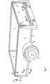
- Fig. 1 die perspektivische Ansicht eines einachsigen Anhängers für Kraftfahrezeuge,
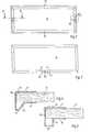
- Fig. 2 die Draufsicht auf eine Seitenwand mit Metallrahmen,
- Fig. 3 Aufsicht auf eine Seitenwand mit Metallrahmen anderer Ausführung,
- Fig. 4 einen Schnitt durch einen Metallrahmen, entlang der Linie V-V der Fig. 2,
- Fig. 5 einen Schnitt durch einen Metallrahmen einer anderen Ausführungsform, ebenfalls entlang dem Querschnitt V-V der Fig. 2,
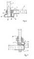
- Fig. 6 eine Eckverbindung zwischen zwei Seitenwandteilen,
- Fig. 7 eine Eckverbindung zwischen Boden und Seitenwand, jeweils im Schnitt,
- Fig. 8 eine andere Ausführungsform der Anbringung eines Verbindungsmittels im Schnitt,
- Fig. 9 einen Längsschnitt zugehörig zur Fig. 8,
- Fig.lo Darstellung des Schnittes des Bodenplattenprofils.
- 1 is a perspective view of a single-axle trailer for motor vehicles,
- 2 is a top view of a side wall with a metal frame,
- 3 top view of a side wall with a metal frame of another design,
- 4 shows a section through a metal frame, along the line VV of FIG. 2,
- 5 shows a section through a metal frame of another embodiment, likewise along the cross section VV of FIG. 2,
- 6 shows a corner connection between two side wall parts,
- 7 is a corner connection between the bottom and side wall, each in section,
- 8 shows another embodiment of the attachment of a connecting means in section,
- 9 is a longitudinal section belonging to FIG. 8,
- Fig.lo representation of the section of the base plate profile.
Ein Fahrzeuganhänger nach derErfindung besteht aus dem Fahrgestell mit den Rädern 1 sowie einer Plattform oder Bodenplatte 2, den Seitenwänden 3 und der Vorderwand 4 sowie der Rückwand 5. Die einzelnen Wände bestehen aus Holz, Holzmaterial oder auch aus einem anderen Material, und sie sind von Metallprofilen allseits umgeben.A vehicle trailer according to the invention consists of the chassis with the
Entsprechend den Figuren 4 und 5 haben die Metallrahmen, die die Platte 6 umgeben, zwei miteinander parallele Schenkel, und zwar einen inneren Schenkel 7 und einen äußeren Schenkel 8. Von dem inneren Schenkel 7 ist das Rahmenprofil um die Kante 9 der Wandplatte herumgebogen bzw. abgewinkelt und bildet ein Mittelteil 10, das auf einer Seite diese Kante 9 der Platte 6 überragt. Mittelteil 1o und Schenkel 7 haben vorzugsweise gleiche Länge. Derjenige Teil des Mittelteils lo, der die Stärke der Platte 6 überragt, ist mindestens etwa so lang wie der halben Plattenstärke 6 entspricht. Nach dem Ausführungsbeispiel in Fig. 4 kann von dem äußeren Ende des Mittelteils 1o mit einem Doppelknick 11 eine Schrägverbindung 12 zu dem Schenkel 8 des Profils erfolgt sein. Zwischen dem Schenkel 8 und dem schrägen Teil 12 ist dann ein stumpfer Winkel vorhanden,währendzwischen dem Mittelteil 1o und dem schrägen Teil 12 ein spitzer Winkel vorhanden ist.According to FIGS. 4 and 5, the metal frames which surround the
Nach dem anderen Ausführungsbeispiel, der Fig. 5, ist von dem Mittelteil an dem Ende des überragenden Teiles zunächst eine rechtwinklige Abwinklung 13 vorgenommen, und von dieser führt eine weitere rechtwinklige Abwinklung 14 zu dem Schenkel 8 des Rahmenprofils.According to the other exemplary embodiment, FIG. 5, there is first one of the middle part at the end of the projecting part made right-
In den Figuren 2 und 3 sind verschiedene Ausführungen der gesamten Anordnung des Rahmens dargestellt. Nach der Figur besteht der Rahmen, der eine Seitenwand 3, 4 oder 5 umgibt, aus zwei Teilen 15 und 16, die spiegelsymmetrisch sind und von oben bzw. unten über die Platte geschoben sind. Zur Verbindung sind Löcher 17 angeordnet, von denen zwei in den beiden gegeneinanderstoßenden Endungen 18 der Rahmenteile liegen. Ein weiteres der Löcher 17 kann auch in der Platte 6 liegen. Diese der Verbindung der beiden Rahmenteile dienenden Löcher, dienen gleichzeitig zur Anbringung von Beschlägen, in dem hier vorliegenden Fall beispielsweise zur Anbringung eines Schließbeschlages, in dem Falle, daß es sich um eine Rückwand 5 handelt.In Figures 2 and 3 different versions of the entire arrangement of the frame are shown. According to the figure, the frame, which surrounds a
Nach der Figur 3 ist der gesamte, die Platte 6 umgebende Rahmen durchgehend einteilig ausgebildet, an den Ecken sind Gehrungen eingeschnitten, so daß die die äußeren Rahmenkanten bildenden Teile der Profile abzuwinkeln sind. Lediglich eine einzige Stoßstelle 19 ist vorhanden, die auch in diesem Falle wieder mittels eines, zweckmäßig an dieser Stelle anzubringenden Beschlages, beispielsweise des Beschlages zur Verbindung mit der Deichsel, mit Löchern 17 versehen ist, wenn es sich um eine Vorderwand 4 handelt.According to Figure 3, the entire frame surrounding the
Ein hier nicht dargestelltes Ausführungsbeispiel ist auf eine Seitenwand 3 anwendbar. Danach ist der umgebende Profilrahmen für die Seitenwand 3 derart ausgebildet, daß ere ähnlich wie bei Fig. 3 sämtliche Seitenkanten umgibt, an der unteren Seitenkante jedoch zwischen den Stößen 19 ein größerer Abstand freibleibt. Hier wird ein gesondertes Profilrahmenteil eingesetzt, und an den in diesem Falle doppelten Stößen befinden sich die Anbringungspunkte für Befestigungsmittel des Schutzbleches 26, das den oberen Teil des Rades 1 umgibt.An embodiment not shown here is applicable to a side wall 3. Thereafter, the surrounding profile frame for the side wall 3 is formed such that it surrounds all side edges similar to FIG. 3, but at the lower side edge between the
In der Figur 6 ist die Eckverbindung zweier Seitenwände dargestellt. Beispielsweise ist die Seitenwand 3 mit der Stirnwand 4 verbunden. Das Mittelteil lo des Rahmenprofils der Seitenwand 3 ist gegen den etwa gleich langen Schenkel 7 des Rahmenprofils der Stirnwand 4 angelegt. Im Bereich der Stirnkante die Seitenwand bildenden Platte 6 sind die beiden aufeinanderliegenden Teile mit einem Durchgangsloch versehen. Fluchtend zu diesem Durchgangsloch ist die Platte 6 der Stirnwand 4 mit einem Durchgangsloch versehen und ebenfalls der Schenkel 8 an der Außenseite der Stirnwand. Schon bei der Herstellung der Seitenwand 3, vor dem Aufsetzen des Rahmens kann in einer Aussparung der Platte 6, die der Rahmenlochung zugeordnet ist, eine Schraube mit ihrem Kopf derart eingesetzt sein, daß sie mit ihrem Schaft aus dem Rahmen der Seitenwand herausragt. Der Schaft dieser Schraube wird durch die Durchgangslöcher der Stirnwand hindurchgeführt,und an der Außenseite wird eine Mutter aufgeschraubt. Es kann auch innerhalb des Mittelteils 1o des Rahmens der Seitenwand eine Schweißmutter auf das Loch im Mittelteil 1o des Rahmens aufgesetzt sein, so daß von außen her durch die vorbereitete Lochung in der Stirnwand 4 eine Schraube in diese Schweißmutter eingeschraubt werden kann. In jedem Fall ist der eine Teil dieser Schraubverbindung unsichtbar und gegen Beschädigungen geschützt. Der offenliegende Teil der Verbindung wird überragt durch den vorspringenden Teil des Rahmens der Stirnwand 4. Dieser vorspringende Teil besteht aus der Verlängerung des Mittelteils 1o sowie den abgewinkelten Teilen 13 und 14.FIG. 6 shows the corner connection of two side walls. For example, the side wall 3 is connected to the
Bei der Verwendung einer Schweißmutter innerhalb des Rahmens der Seitenwand 3 kann diese auch entsprechend den Figuren 8 und 9 angeordnet sein. Im Bereich der Schweißmutter ist der Mittelteil lo des Rahmens an der Profilwandung um etwa die Stärke dieser Wandung nach innen versetzt, so daß beispielsweise zwischen den beiden aufeinanderliegenden Rahmenteilen noch Raum für die Anbringung einerZwischenlegscheibe besteht, die aus einem elastischen Material bestehen kann. Die Schweißmutter 19 ist vorzugsweise im Bereich der Kante 9 der eingesetzten Platte 6 angeordnet, und zu diesem Zweck ist die Platte an dieser Stelle mit einer Ausnehmung versehen. Die Schweißmutter19 kann jedoch auch im Bereich der "Auswölbung" des Rahmenprofils von innen auf das verlängerte Mittelteil 1o gegenüber dem Profilteil 14 aufgesetzt sein, das bedingt, daß die Seitenwand 3 in der Verbindung weiter nach innen gerückt ist und die "Auswölbung" des Profils des Rahmens der Seitenwand 3 fluchtend mit dem Loch in den beiden Schenkeln 7 und 8 des Profils des Rahmens der Stirnwand 4 liegt.When using a welding nut within the frame of the side wall 3, this can also be arranged in accordance with FIGS. 8 and 9. In the area of the weld nut, the central part lo of the frame on the profile wall is offset inward by approximately the thickness of this wall, so that, for example, there is still space between the two superposed frame parts for the attachment of aZ intermediate washer, which consists of an elastic Material can exist. The
Die"Auswölbung" überragt auch die Befestigungsmittel bzw. deren Köpfe für den Rahmen auf einer Seitenwand selbst. Diese Befestigungen werden im allgemeinen mit Nieten vorgenommen, bei denen die Köpfe flach linsenförmig ausgebildet sind, so daß dadurchkeine wesentlichen Vorsprünge über die Ebene der Seitenwand nach außen oder innen vorhanden sind. Bei einer Rahmenausbildung nach der Neuerung ist jedoch die Möglichkeit gegeben, die mit einer derartigen Nietenbefestigung des Profilrahmens verbundenen Nachteile zu vermeiden, es können vielmehr auch zur Befestigung des Rahmens an der Platte Schrauben verwendet werden, die auf den langen Schenkel 8 mit flachen Linsenköpfen aufliegen, während sie auf der gegenüberliegenden Seite, dem kurzen Schenkel 8, beispielsweise mit Kopfmuttern gesichert sind. Daß diese Kopfmuttern weiter vorstehen, spielt keine Rolle, denn sie sind geschützt und überdeckt durch die "Auswölbungen" des Rahmenprofils. Gleiches trifft zu für die Befestigung sämtlicher Beschläge, wie beispielsweise Scharniere 2o für die Rückwandklappe , und Befestigungen und Riegelverschlüsse 21 ebenfalls für die Rückwandklappe.The "bulge" also extends beyond the fasteners or their heads for the frame on a side wall itself. These fastenings are generally carried out with rivets in which the heads are flat, lenticular, so that there are no significant projections beyond the plane of the side wall or are present inside. In the case of a frame design according to the innovation, however, there is the possibility of avoiding the disadvantages associated with such a rivet fastening of the profile frame. Rather, screws can also be used for fastening the frame to the plate, which lie on the
Die Ausbildung der Boden-Plattform und die Verbindung der Wände mit der Plattform ist auf die folgende Art durchgeführt:
- Bei
dem unteren Schenkel 22 ist durch eine Abwinklung ein die Kante der Bodenplatte bzw. Plattform abdeckendes Mittelteil 23 erzeugt, von der wiederum der obereSchenkel 24 nach innen abgewinkelt ist. Daran schließt sich eine hochstehende Abwinklung 25 an, deren Länge etwa der Länge des langen Flansches 7 der Rahmenprofile der Seitenwandungen entspricht.Aus der Figur 7 ist zu erkennen wie die Verbindung hergestellt ist. Es ist weiterhin daraus auch zu erkennen, daß der obereSchenkel 24 in der Länge etwa dem Mittelstück 1o der Seitenwandprofile entspricht, so daß beim Einsetzen der Seitenwände das Mittelteil 1o und derlange Flansch 7 parallelzu dem Schenkel 24 des Bodenprofils unddem hochstehenden Teil 25 des Bodenprofils verlaufen, wobei das letztere an seiner Oberkante mit einer nach außen gerichteten Abwinklung versehen ist, die die entsprechende Abwinklung an dem langen Schenkel des Profils des Rahmens der Seitenwandungen übergreift. Beim Einsetzen der Seitenwandungen in das Profil des Bodens wird also eine teilweise formschlüssige Anlage erreicht. Die Verbindung erfolgt mit-, telsSchrauben oder Schweißmuttern 19, wie das zuvor schon in Zusammenhang mit der Verbindung der Seitenwände untereinander anhand der Figur 6 beschrieben ist. Ein weitere Verbindung kann oberhalb dieser Eckverbindung mittels Durchführen einer Schraube durch die parallel zueinander liegenden Schenkel der Seitenwandprofile unddas hochstehende Teil 25 des Bodenprofils erfolgen. Es ist damit eine besonders gute Sicherung dieser Eckverbindung erreicht. Die obere Verbindung kann zusätzlich benutzt werden, um beispielsweise die seitlichen Kotflügel 26 zu befestigen.
- In the case of the
lower leg 22, amiddle part 23 covering the edge of the base plate or platform is produced by an angling, from which in turn theupper leg 24 is angled inwards. This is followed by anupstanding bend 25 whose length corresponds approximately to the length of thelong flange 7 of the frame profiles of the side walls. It can be seen from FIG. 7 how the connection is established. It can also be seen therefrom that the length of theupper leg 24 corresponds approximately to themiddle piece 10 of the side wall profiles, so that when the side walls are inserted, themiddle part 10 and thelong flange 7 parallel to theleg 24 of the floor profile and theupstanding part 25 of the floor profile, the latter being provided on its upper edge with an outward angled portion which overlaps the corresponding angled portion on the long leg of the profile of the frame of the side walls. When the side walls are inserted into the profile of the floor, a partially positive fit is achieved. The connection is made by means of screws or weld nuts 19, as described above in connection with the connection of the side walls to one another with reference to FIG. 6. Another connection can be made above this corner connection by passing a screw through the parallel legs of the side wall profiles and theupstanding part 25 of the floor profile. A particularly good securing of this corner connection is thus achieved. The upper connection can also be used, for example, to attach theside fenders 26.
Claims (15)
Translated fromGermanApplications Claiming Priority (2)
| Application Number | Priority Date | Filing Date | Title |
|---|---|---|---|
| DE8132786U | 1981-11-10 | ||
| DE19818132786DE8132786U1 (en) | 1981-11-10 | 1981-11-10 | TRAILER FOR MOTOR VEHICLES |
Publications (3)
| Publication Number | Publication Date |
|---|---|
| EP0079068A2true EP0079068A2 (en) | 1983-05-18 |
| EP0079068A3 EP0079068A3 (en) | 1983-09-07 |
| EP0079068B1 EP0079068B1 (en) | 1986-10-29 |
Family
ID=6732866
Family Applications (2)
| Application Number | Title | Priority Date | Filing Date |
|---|---|---|---|
| EP82110260AExpiredEP0087504B1 (en) | 1981-11-10 | 1982-11-06 | Trailer for motor vehicles |
| EP82110261AExpiredEP0079068B1 (en) | 1981-11-10 | 1982-11-06 | Trailer for motor vehicles |
Family Applications Before (1)
| Application Number | Title | Priority Date | Filing Date |
|---|---|---|---|
| EP82110260AExpiredEP0087504B1 (en) | 1981-11-10 | 1982-11-06 | Trailer for motor vehicles |
Country Status (3)
| Country | Link |
|---|---|
| EP (2) | EP0087504B1 (en) |
| DE (1) | DE8132786U1 (en) |
| DK (2) | DK155719C (en) |
Cited By (5)
| Publication number | Priority date | Publication date | Assignee | Title |
|---|---|---|---|---|
| FR2807991A1 (en)* | 2000-04-21 | 2001-10-26 | Amca Noval | Lightweight modular car trailer has supports with slideways on at least one side of body to allow side panel to be fitted by vertical movement |
| KR100364251B1 (en)* | 2000-04-15 | 2002-12-11 | 옵티시스 주식회사 | Universal Serial Bus connecting apparatus |
| US6669271B2 (en)* | 2001-06-22 | 2003-12-30 | East Manufacturing Corporation | Smooth side body structure and method |
| US7152909B2 (en) | 2001-06-22 | 2006-12-26 | East Manufacturing Corporation | Trailer and trailer body construction and extruded panel for same |
| EP1757516A1 (en)* | 2005-08-26 | 2007-02-28 | Linamar Corporation | Trailer with multi position tailgate |
Families Citing this family (3)
| Publication number | Priority date | Publication date | Assignee | Title |
|---|---|---|---|---|
| EP0235330B1 (en)* | 1986-03-04 | 1990-01-03 | Waldemar Heinemann GmbH & Co. KG | Trailer for a passenger vehicle |
| SE458110B (en)* | 1987-06-26 | 1989-02-27 | Gisebo Vagnindustri Ab | HAIRSTOLPE FOR SLAEPKAERRA |
| DE202018001409U1 (en) | 2018-03-16 | 2019-06-18 | Jansen Ag | frame profile |
Family Cites Families (3)
| Publication number | Priority date | Publication date | Assignee | Title |
|---|---|---|---|---|
| DE7126992U (en)* | 1971-10-28 | Brandt W | Profile bar or frame, especially for plastic sheets and the like | |
| DE802212C (en)* | 1949-01-14 | 1951-02-05 | Ernst Hahn | Method for producing a trailer box body and box body, in particular for trailers of passenger cars |
| DE8211026U1 (en)* | 1982-04-19 | 1982-08-12 | Schultheis, Wilhelm, 6050 Offenbach | AUTOMATIC LIFTING AND SWIVELING DEVICE FOR BARRELS OR THE LIKE |
- 1981
- 1981-11-10DEDE19818132786patent/DE8132786U1/ennot_activeExpired
- 1982
- 1982-11-06EPEP82110260Apatent/EP0087504B1/ennot_activeExpired
- 1982-11-06EPEP82110261Apatent/EP0079068B1/ennot_activeExpired
- 1982-11-09DKDK498282Apatent/DK155719C/ennot_activeIP Right Cessation
- 1982-11-09DKDK498182Apatent/DK155426C/ennot_activeIP Right Cessation
Cited By (13)
| Publication number | Priority date | Publication date | Assignee | Title |
|---|---|---|---|---|
| KR100364251B1 (en)* | 2000-04-15 | 2002-12-11 | 옵티시스 주식회사 | Universal Serial Bus connecting apparatus |
| FR2807991A1 (en)* | 2000-04-21 | 2001-10-26 | Amca Noval | Lightweight modular car trailer has supports with slideways on at least one side of body to allow side panel to be fitted by vertical movement |
| US7152909B2 (en) | 2001-06-22 | 2006-12-26 | East Manufacturing Corporation | Trailer and trailer body construction and extruded panel for same |
| US6929311B2 (en) | 2001-06-22 | 2005-08-16 | East Manufacturing Corporation | Smooth side body structure and method |
| US7014252B2 (en) | 2001-06-22 | 2006-03-21 | East Manufacturing Corporation | Trailer construction using vertical extruded aluminum panels |
| US7100972B2 (en) | 2001-06-22 | 2006-09-05 | East Manufacturing Corporation | Trailer wall structure defined by vertical extruded aluminum panels |
| US6669271B2 (en)* | 2001-06-22 | 2003-12-30 | East Manufacturing Corporation | Smooth side body structure and method |
| US7267393B2 (en) | 2001-06-22 | 2007-09-11 | East Manufacturing Corporation | Trailer and trailer body construction and extruded panel for same |
| US7296846B2 (en) | 2001-06-22 | 2007-11-20 | East Manufacturing Corporation | Trailer wall structure defined by vertical extruded aluminum panels |
| US7390053B2 (en) | 2001-06-22 | 2008-06-24 | East Manufacturing Corporation | Trailer and trailer body construction and extruded panel for same |
| US7762617B2 (en) | 2001-06-22 | 2010-07-27 | East Manufacturing Corporation | Trailer and trailer body construction and extruded panel for same |
| US7950722B2 (en) | 2001-06-22 | 2011-05-31 | East Manufacturing Corporation | Smooth side body structure and method |
| EP1757516A1 (en)* | 2005-08-26 | 2007-02-28 | Linamar Corporation | Trailer with multi position tailgate |
Also Published As
| Publication number | Publication date |
|---|---|
| EP0087504A1 (en) | 1983-09-07 |
| EP0087504B1 (en) | 1988-10-12 |
| DK498182A (en) | 1983-05-11 |
| EP0079068B1 (en) | 1986-10-29 |
| DK155719C (en) | 1989-09-25 |
| DK155426B (en) | 1989-04-10 |
| DK498282A (en) | 1983-05-11 |
| DE8132786U1 (en) | 1982-04-22 |
| DK155426C (en) | 1989-08-21 |
| EP0079068A3 (en) | 1983-09-07 |
| DK155719B (en) | 1989-05-08 |
Similar Documents
| Publication | Publication Date | Title |
|---|---|---|
| DE69104687T2 (en) | METAL FRAME FOR A CABINET. | |
| DE19638156B4 (en) | Structure for the upper body portion of a vehicle body | |
| DE69423972T2 (en) | FINAL SECTION OF A FRAME PART FOR A VEHICLE | |
| DE2829671A1 (en) | CORNER CONNECTION FOR THE ROLL-ON PROTECTION ON VEHICLES FORMING, IN A CORNER, BEARING, STRUTS, SUPPORTS O.DGL. | |
| DE2945550A1 (en) | LOAD CARRIER | |
| DE3343682A1 (en) | CARRYING STRUCTURE FOR A MOTOR VEHICLE | |
| EP0267152B1 (en) | Set of profiles for the body framework of utility vehicles | |
| DE29800368U1 (en) | Screwed subframe | |
| DE2638440A1 (en) | ROLL-OVER FRAME FOR MOTOR VEHICLES | |
| EP0079068B1 (en) | Trailer for motor vehicles | |
| DE3303306A1 (en) | Snow guard device | |
| DE9418262U1 (en) | Profile arrangement and its use for the production of frame profiles for superstructures | |
| EP2524855B1 (en) | Structure for a commercial vehicle | |
| DE3927082A1 (en) | Motor vehicle bumper structure | |
| DE10144213C1 (en) | Bearer for vehicle frame has bearer parts with complementary teeth | |
| DE9308329U1 (en) | Frame of a commercial vehicle | |
| DE20021088U1 (en) | Base frame of containers and trailers for motor vehicles | |
| DE69204672T2 (en) | FRAME PART FOR A VEHICLE. | |
| DE2728963C3 (en) | Stake for trucks and trailers | |
| DE8030653U1 (en) | HARDTOP FOR MOTOR VEHICLES | |
| DE2949684A1 (en) | Trailer for transporting horses - has light alloy chassis comprising box section base frame with flange extensions for side wall fixings | |
| DE3247078A1 (en) | Stake for lorries and trailers | |
| DE4036413C2 (en) | Crossbeam for containers and swap bodies | |
| DE8219290U1 (en) | Single or tandem axle motor vehicle trailer | |
| DE8715774U1 (en) | Wardrobe |
Legal Events
| Date | Code | Title | Description |
|---|---|---|---|
| PUAI | Public reference made under article 153(3) epc to a published international application that has entered the european phase | Free format text:ORIGINAL CODE: 0009012 | |
| AK | Designated contracting states | Designated state(s):BE FR NL | |
| PUAL | Search report despatched | Free format text:ORIGINAL CODE: 0009013 | |
| AK | Designated contracting states | Designated state(s):BE FR NL | |
| 17P | Request for examination filed | Effective date:19831014 | |
| GRAA | (expected) grant | Free format text:ORIGINAL CODE: 0009210 | |
| AK | Designated contracting states | Kind code of ref document:B1 Designated state(s):BE FR NL | |
| ET | Fr: translation filed | ||
| PLBE | No opposition filed within time limit | Free format text:ORIGINAL CODE: 0009261 | |
| STAA | Information on the status of an ep patent application or granted ep patent | Free format text:STATUS: NO OPPOSITION FILED WITHIN TIME LIMIT | |
| 26N | No opposition filed | ||
| PGFP | Annual fee paid to national office [announced via postgrant information from national office to epo] | Ref country code:FR Payment date:19931115 Year of fee payment:12 | |
| PGFP | Annual fee paid to national office [announced via postgrant information from national office to epo] | Ref country code:BE Payment date:19931208 Year of fee payment:12 | |
| PG25 | Lapsed in a contracting state [announced via postgrant information from national office to epo] | Ref country code:BE Effective date:19941130 | |
| PGFP | Annual fee paid to national office [announced via postgrant information from national office to epo] | Ref country code:NL Payment date:19941130 Year of fee payment:13 | |
| BERE | Be: lapsed | Owner name:WESTFALIA-WERKE FRANZ KNOBEL & SOHNE K.G. Effective date:19941130 | |
| PG25 | Lapsed in a contracting state [announced via postgrant information from national office to epo] | Ref country code:FR Effective date:19950731 | |
| REG | Reference to a national code | Ref country code:FR Ref legal event code:ST | |
| PG25 | Lapsed in a contracting state [announced via postgrant information from national office to epo] | Ref country code:NL Effective date:19960601 | |
| NLV4 | Nl: lapsed or anulled due to non-payment of the annual fee | Effective date:19960601 |