EP0078139B1 - Reduction gear having a magnet clutch mechanism - Google Patents
Reduction gear having a magnet clutch mechanismDownload PDFInfo
- Publication number
- EP0078139B1 EP0078139B1EP82305541AEP82305541AEP0078139B1EP 0078139 B1EP0078139 B1EP 0078139B1EP 82305541 AEP82305541 AEP 82305541AEP 82305541 AEP82305541 AEP 82305541AEP 0078139 B1EP0078139 B1EP 0078139B1
- Authority
- EP
- European Patent Office
- Prior art keywords
- yoke
- armature
- worm wheel
- casing
- annular
- Prior art date
- Legal status (The legal status is an assumption and is not a legal conclusion. Google has not performed a legal analysis and makes no representation as to the accuracy of the status listed.)
- Expired
Links
Images

Classifications
- F—MECHANICAL ENGINEERING; LIGHTING; HEATING; WEAPONS; BLASTING
- F16—ENGINEERING ELEMENTS AND UNITS; GENERAL MEASURES FOR PRODUCING AND MAINTAINING EFFECTIVE FUNCTIONING OF MACHINES OR INSTALLATIONS; THERMAL INSULATION IN GENERAL
- F16D—COUPLINGS FOR TRANSMITTING ROTATION; CLUTCHES; BRAKES
- F16D27/00—Magnetically- or electrically- actuated clutches; Control or electric circuits therefor
- F16D27/10—Magnetically- or electrically- actuated clutches; Control or electric circuits therefor with an electromagnet not rotating with a clutching member, i.e. without collecting rings
- E—FIXED CONSTRUCTIONS
- E05—LOCKS; KEYS; WINDOW OR DOOR FITTINGS; SAFES
- E05F—DEVICES FOR MOVING WINGS INTO OPEN OR CLOSED POSITION; CHECKS FOR WINGS; WING FITTINGS NOT OTHERWISE PROVIDED FOR, CONCERNED WITH THE FUNCTIONING OF THE WING
- E05F15/00—Power-operated mechanisms for wings
- E05F15/60—Power-operated mechanisms for wings using electrical actuators
- E05F15/603—Power-operated mechanisms for wings using electrical actuators using rotary electromotors
- F—MECHANICAL ENGINEERING; LIGHTING; HEATING; WEAPONS; BLASTING
- F16—ENGINEERING ELEMENTS AND UNITS; GENERAL MEASURES FOR PRODUCING AND MAINTAINING EFFECTIVE FUNCTIONING OF MACHINES OR INSTALLATIONS; THERMAL INSULATION IN GENERAL
- F16D—COUPLINGS FOR TRANSMITTING ROTATION; CLUTCHES; BRAKES
- F16D27/00—Magnetically- or electrically- actuated clutches; Control or electric circuits therefor
- F16D27/10—Magnetically- or electrically- actuated clutches; Control or electric circuits therefor with an electromagnet not rotating with a clutching member, i.e. without collecting rings
- F16D27/108—Magnetically- or electrically- actuated clutches; Control or electric circuits therefor with an electromagnet not rotating with a clutching member, i.e. without collecting rings with axially movable clutching members
- F16D27/112—Magnetically- or electrically- actuated clutches; Control or electric circuits therefor with an electromagnet not rotating with a clutching member, i.e. without collecting rings with axially movable clutching members with flat friction surfaces, e.g. discs
- F—MECHANICAL ENGINEERING; LIGHTING; HEATING; WEAPONS; BLASTING
- F16—ENGINEERING ELEMENTS AND UNITS; GENERAL MEASURES FOR PRODUCING AND MAINTAINING EFFECTIVE FUNCTIONING OF MACHINES OR INSTALLATIONS; THERMAL INSULATION IN GENERAL
- F16H—GEARING
- F16H1/00—Toothed gearings for conveying rotary motion
- F16H1/02—Toothed gearings for conveying rotary motion without gears having orbital motion
- F16H1/04—Toothed gearings for conveying rotary motion without gears having orbital motion involving only two intermeshing members
- F16H1/12—Toothed gearings for conveying rotary motion without gears having orbital motion involving only two intermeshing members with non-parallel axes
- F16H1/16—Toothed gearings for conveying rotary motion without gears having orbital motion involving only two intermeshing members with non-parallel axes comprising worm and worm-wheel
- E—FIXED CONSTRUCTIONS
- E05—LOCKS; KEYS; WINDOW OR DOOR FITTINGS; SAFES
- E05Y—INDEXING SCHEME ASSOCIATED WITH SUBCLASSES E05D AND E05F, RELATING TO CONSTRUCTION ELEMENTS, ELECTRIC CONTROL, POWER SUPPLY, POWER SIGNAL OR TRANSMISSION, USER INTERFACES, MOUNTING OR COUPLING, DETAILS, ACCESSORIES, AUXILIARY OPERATIONS NOT OTHERWISE PROVIDED FOR, APPLICATION THEREOF
- E05Y2201/00—Constructional elements; Accessories therefor
- E05Y2201/20—Brakes; Disengaging means; Holders; Stops; Valves; Accessories therefor
- E05Y2201/214—Disengaging means
- E05Y2201/216—Clutches
- E—FIXED CONSTRUCTIONS
- E05—LOCKS; KEYS; WINDOW OR DOOR FITTINGS; SAFES
- E05Y—INDEXING SCHEME ASSOCIATED WITH SUBCLASSES E05D AND E05F, RELATING TO CONSTRUCTION ELEMENTS, ELECTRIC CONTROL, POWER SUPPLY, POWER SIGNAL OR TRANSMISSION, USER INTERFACES, MOUNTING OR COUPLING, DETAILS, ACCESSORIES, AUXILIARY OPERATIONS NOT OTHERWISE PROVIDED FOR, APPLICATION THEREOF
- E05Y2201/00—Constructional elements; Accessories therefor
- E05Y2201/20—Brakes; Disengaging means; Holders; Stops; Valves; Accessories therefor
- E05Y2201/23—Actuation thereof
- E05Y2201/246—Actuation thereof by auxiliary motors, magnets, springs or weights
- E—FIXED CONSTRUCTIONS
- E05—LOCKS; KEYS; WINDOW OR DOOR FITTINGS; SAFES
- E05Y—INDEXING SCHEME ASSOCIATED WITH SUBCLASSES E05D AND E05F, RELATING TO CONSTRUCTION ELEMENTS, ELECTRIC CONTROL, POWER SUPPLY, POWER SIGNAL OR TRANSMISSION, USER INTERFACES, MOUNTING OR COUPLING, DETAILS, ACCESSORIES, AUXILIARY OPERATIONS NOT OTHERWISE PROVIDED FOR, APPLICATION THEREOF
- E05Y2201/00—Constructional elements; Accessories therefor
- E05Y2201/40—Motors; Magnets; Springs; Weights; Accessories therefor
- E05Y2201/46—Magnets
- E05Y2201/462—Electromagnets
- E—FIXED CONSTRUCTIONS
- E05—LOCKS; KEYS; WINDOW OR DOOR FITTINGS; SAFES
- E05Y—INDEXING SCHEME ASSOCIATED WITH SUBCLASSES E05D AND E05F, RELATING TO CONSTRUCTION ELEMENTS, ELECTRIC CONTROL, POWER SUPPLY, POWER SIGNAL OR TRANSMISSION, USER INTERFACES, MOUNTING OR COUPLING, DETAILS, ACCESSORIES, AUXILIARY OPERATIONS NOT OTHERWISE PROVIDED FOR, APPLICATION THEREOF
- E05Y2900/00—Application of doors, windows, wings or fittings thereof
- E05Y2900/50—Application of doors, windows, wings or fittings thereof for vehicles
- E05Y2900/53—Type of wing
- E05Y2900/531—Doors
Definitions
- This inventionrelates to a reduction gear mechanism having a magnet clutch mechanism therein and comprising a worm and a worm wheel.
- a final reduction gearcomprising a worm and a worm wheel in combination is used to multiply output torque of the motor.
- a clutchis interposed between the motor and the final reduction gear which is operable to connect and disconnect transmission of power between them.
- Fig. 1illustrates an example of such a construction, which comprises a motor (a), a clutch (b), a final reduction gear (c) comprising a worm and a worm wheel in combination, and an output power shaft (d).
- This constructionis disadvantageous in that it requires a large spacing for installation.
- the combination of a worm and a worm wheelhas a deficiency that it does not allow a reverse operation thereof from its output side. Accordingly, even if the clutch is disengaged to stop an automatic operation, it does not result in availability of a manual operation from the output side.
- the constructionis modified to increase the lead angle of the worm to reduce the reduction ratio of the reduction gear mechanism, it will enable a reversing operation of the reduction gear mechanism from its output side. But, such modification will not lead to a smooth reversing operation of the reduction gear mechanism since such a reversing operation will be opposed by a load arising at the reduction stage. Also, such modification will result in an employment of a larger motor to meet the requirement of larger torque.
- a reduction gear mechanismis known from US-PS 3,874,117 comprising a casing, an output power shaft supported for rotation on said casing, an armature mounted to said output power shaft within said casing, an annular armature yoke having an annular coil housed within it in an opposing relationship to said armature, a worm wheel which is-rotatably mounted to said casing so as to be rotated freely apart from said coil and said armature when the coil is not energized, and a worm mounted on a driving shaft.
- this mechanismis designed for use as an opener for doors in buildings and the construction is comparatively bulky.
- An object of the present inventionto provide a reduction gear mechanism incorporating a magnet clutch mechanism to facilitate installation of the reduction gear mechanism within a restricted spacing.
- a reduction gear mechanismgenerally of the kind discussed above in relation to US-PS-3,874,117, which is characterised in that said armature is mounted adjacent to the rear side of said casing; said armature yoke is made of magnetic material and has a front side fixed to the front side of the casing and upper and lower sides extending rearwardlytherefrom to define an opening on the rear side of said yoke; at the rear side of said yoke adjacent to said coil an annular non-magnetic member is extended across the opening of said annular yoke; said worm wheel is interposed between said yoke and said armature, and comprises a cylindrical hub portion, an end wall extending from a rear side end of the hub portion, a ring portion extending forwardly from an outer circumferential edge of said end wall, and an annular toothed member integrally fitted on an outer periphery of said ring portion, said hub portion, end wall and ring portion of said worm wheel defining an annular hollow
- the reduction gear mechanismcomprises a casing 1 in the form of a box which is open at the rear thereof.
- the rear opening of the casing 1is covered and closed up by a rear lid 2 to define a room 3 within the casing 1.
- a plurality of flanges 1aare formed around a periphery of the casing 1 to enable mounting of the casing 1.
- a shaft 4 extending in parallel with the rear lid 2is rotatably and horizontally arranged in an lower part of the room 3 of the casing 1 and is supported at opposite end portions 4b and 4c thereof on the casing 1 via respective bushes 5.
- the shaft 4has a worm 4a in its intermediate portion.
- the shaft 4may be connected at a left-hand side end 4c thereof to motor or the like by way of a connecting rod (not shown).
- the casing 1Adjacent to a right-hand side end 4b of the shaft 4, the casing 1 has a threaded hole 6 formed therein in an opposing relationship to the end face of the shaft 4.
- a thread screw 7is screwed in the threaded hole 6 such that an end face of the thread screw 7 presses a steel ball 8 against the center of the end face of the shaft 4.
- the casing 1has a post-like bearing portion 1b formed to extend therefrom into the room 3.
- An output power shaft 9extends through and is mounted on the bearing portion 1b of the casing 1 for rotation and for axial motion by a limited distance.
- a pinion 10is fitted on a forward end of the output shaft 9 which is projected outside the casing 1.
- an armature 11in the form of a disk made of ferromagnetic soft iron and constituting a magnet clutch.
- An annular yoke 12is provided which is made of a magnetic material and presents a channel- like cross section which is open to the rear side of the casing 1.
- the yoke 12is fixed to an inner surface of the casing 1 such that an inner circumferehtial surface of the yoke. 12 is spaced from an outer periphery of the bearing portion 1 b of the casing 1 with a predetermined gap being left therebetween.
- An annular coil 13is inserted in the yoke 12 through the opening on the rear side.
- a lead wire 13a of the coil 13extends through the yoke 12 and the casing 1 and is drawn out to the front side of the casing 1.
- a non-magnetic member 14 made of a synthetic resin materialis mounted to cover the rear open end of the yoke 12 to secure the coil 13 within the yoke 12.
- a worm wheel 15which serves also as a rotor of the magnet clutch.
- the worm wheel 15is made of ferromagnetic soft iron and comprises a cylindrical hub portion 15a, an end wall 15b extending from a rear side of the hub portion 15a, a ring portion 15c extending forwardly from an outer circumferential edge of the end wall 15b, and an annular toothed member 15d made of a suitable synthetic resin material and integrally fitted on an outer periphery of the ring portion 15c.
- the hub portion 15a of the worm wheel 15is fitted for rotation around the bearing portion 1 b of the casing 1 and has its outer peripheral surface opposed to an inner peripheral surface of the yoke 12 with a slight gap being left therebetween.
- a front end face of the end wall 15b of the worm wheel 15is opposed to the non-magnetic member 14 of the yoke 12 with a slight gap being left therebetween while a rear end face of the end wall 15b is opposed to a front end face of the armature 11 also with a slight gap being left therebetween.
- an inner peripheral surface of the ring portion 15c of the worm wheel 15is opposed to an outer peripheral surface of the yoke 12 with a slight gap being left therebetween.
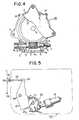
- the toothed member 15d of the worm wheel 15is always in a meshing engagement with the worm 4a, as apparently seen in Fig. 4.
- the worm wheel 15can be freely rotated around the bearing portion 1b of the casing 1, apart from the armature 11, the yoke 12, the coil 13 and the non-magnetic member 14 when the coil 13 is not actuated, while the yoke 12, the coil 13 and the non-magnetic member 14 are fitted in the annular hollow defined by the hub portion 15a, the end wall 15b and the ring portion 15c of the worm wheel 15 with a slight gap therebetween.
- a snap ring 16is fitted in a groove formed in the rear end portion of the bearing portion 1b of the casing 1, and prevents the worm wheel 15 from coming out rearwards.
- An O-ring 17is fitted in a groove formed on and around the outer periphery of the output power shaft 9 in its front end portion.
- a washer 18is-fifted on the output power shaft 9 adjacent to the rear end of the pinion 10, and prevents the output power shaft 9 from further moving rearwards.
- a plurality of screws 19are used for mounting the rear lid 2 to the casing 1.
- the worm wheel 15on one hand, cooperates with the worm 4a to provide a speed reducing function, and on the other hand, acts as a rotor of the magnet clutch with reference to the armature 11.
- FIG. 5there is illustrated an exemplary application of the mechanism according to the present invention to an automatic door opening and closing apparatus of an automobile, which is one of applications which can present the maximum effect of the invention the spirit of which resides in simultaneous employment of a magnet clutch and a reduction gear in a reduction gear mechanism.
- the automobilehas a rear door 20 mounted for opening and closing motion on a car body (not shown) by means of a door hinge (not shown).
- the door 20has a motor 21 fixedly mounted thereon to which a reduction gear mechanism 22 including a clutch mechanism according to the present invention is directly connected.
- a sector gear 23is supported at a central portion thereof for pivotal motion on the door 20 by means of a pivot 24.
- the sector gear 23has a toothed edge 23a which is meshed with the pinion 10 of the reduction gear 22.
- a push rod 25is pivotally connected at a rear end thereof to an upper end of the sector gear 23 by means of a pin 26 and is pivotally connected at a front end thereof to a bracket 28 by means of a pivot 27.
- the bracket 28is fixedly mounted on a center pillar 29 located at the center of the car body of the automobile.
- a switch(not shown in the drawings) is turned on to bring the clutch mechanism included in the reduction gear mechanism into engagement to allow the motor 21 to rotate in the forward or reverse direction.
- the sector gear 23is pivoted in the clockwise or counterclockwise direction as viewed in Fig. 5 through the pinion 10 of the reduction gear mechanism 22, and thereupon the push rod 25 is pushed or pulled in an axial direction thereof to open or close the door 20.
- the reduction gear mechanism 22includes a clutch mechanism therein which allows disconnection of transmission of such a force so that the output power shaft can be rotated independently. Accordingly, manual opening and closing operations of the door can be easily carried out without being confronted by a resisting force of the motor, the reduction gear mechanism, and so on.
- a reduction gear mechanismcomprising a worm and a worm wheel includes a magnet clutch, wherein a coil is disposed in one side of the worm wheel which serves as a rotor, while an armature is disposed in the other side of the same.
- the reduction gear mechanismacts as a normal reduction gear.
- the output shaftcan be rotated freely.
- a reduction gear mechanism according to the present inventionis incorporated in an automatic door opening and closing apparatus of an automobile, the door can be advantageously opened or closed by a manual operation thereof.
- a reduction gear mechanism according to the present inventioncan be incorporated also in any other device or apparatus which requires automatic operations as well as manual operations thereof.
- a reduction gear mechanism according to the present inventionhas a great number of applications thereof.
- a reduction gear mechanismincludes a magnet clutch mechanism incorporated therein although it has a similar overall size to that of a conventional reduction gear. Consequently, it can be installed where a space is restricted, for example, in a door of an automobile and so on.
- the magnet clutchis of the type utilizing friction, it only produces very small attracting noises upon engagement and disengagement thereof. Also, an electric current for energizing a coil can be reduced sufficiently weak, and hence it is apparently economical.
Landscapes
- Engineering & Computer Science (AREA)
- General Engineering & Computer Science (AREA)
- Mechanical Engineering (AREA)
- Physics & Mathematics (AREA)
- Electromagnetism (AREA)
- Connection Of Motors, Electrical Generators, Mechanical Devices, And The Like (AREA)
- Power-Operated Mechanisms For Wings (AREA)
Description
- This invention relates to a reduction gear mechanism having a magnet clutch mechanism therein and comprising a worm and a worm wheel.
- Conventionally, automobiles and the like vehicles commonly employ an electric motor as a source of a driving force to automatically operate various devices and apparatus provided therein.
- In such conventional automobiles, a final reduction gear comprising a worm and a worm wheel in combination is used to multiply output torque of the motor. A clutch is interposed between the motor and the final reduction gear which is operable to connect and disconnect transmission of power between them.
- Fig. 1 illustrates an example of such a construction, which comprises a motor (a), a clutch (b), a final reduction gear (c) comprising a worm and a worm wheel in combination, and an output power shaft (d).
- This construction, however, is disadvantageous in that it requires a large spacing for installation.
- Besides, the combination of a worm and a worm wheel has a deficiency that it does not allow a reverse operation thereof from its output side. Accordingly, even if the clutch is disengaged to stop an automatic operation, it does not result in availability of a manual operation from the output side.
- If the construction is modified to increase the lead angle of the worm to reduce the reduction ratio of the reduction gear mechanism, it will enable a reversing operation of the reduction gear mechanism from its output side. But, such modification will not lead to a smooth reversing operation of the reduction gear mechanism since such a reversing operation will be opposed by a load arising at the reduction stage. Also, such modification will result in an employment of a larger motor to meet the requirement of larger torque.
- A reduction gear mechanism is known from US-PS 3,874,117 comprising a casing, an output power shaft supported for rotation on said casing, an armature mounted to said output power shaft within said casing, an annular armature yoke having an annular coil housed within it in an opposing relationship to said armature, a worm wheel which is-rotatably mounted to said casing so as to be rotated freely apart from said coil and said armature when the coil is not energized, and a worm mounted on a driving shaft. However this mechanism is designed for use as an opener for doors in buildings and the construction is comparatively bulky.
- An object of the present invention to provide a reduction gear mechanism incorporating a magnet clutch mechanism to facilitate installation of the reduction gear mechanism within a restricted spacing.
- It is another object of the invention to provide a reduction gear mechanism which allows a rotational operation, and especially a manual rotation operation, of the same from its output side.
- According to the present invention, there is provided a reduction gear mechanism generally of the kind discussed above in relation to US-PS-3,874,117, which is characterised in that said armature is mounted adjacent to the rear side of said casing; said armature yoke is made of magnetic material and has a front side fixed to the front side of the casing and upper and lower sides extending rearwardlytherefrom to define an opening on the rear side of said yoke; at the rear side of said yoke adjacent to said coil an annular non-magnetic member is extended across the opening of said annular yoke; said worm wheel is interposed between said yoke and said armature, and comprises a cylindrical hub portion, an end wall extending from a rear side end of the hub portion, a ring portion extending forwardly from an outer circumferential edge of said end wall, and an annular toothed member integrally fitted on an outer periphery of said ring portion, said hub portion, end wall and ring portion of said worm wheel defining an annular hollow in which said annularyoke is matingly housed; and said worm is in continuous meshing engagement with said annular toothed member of said worm wheel, whereby upon energization of said coil, said armature is magnetically attracted to said worm wheel thereby to contact transmission of rotation of said worm to said armature and said output power shaft.
- It will be appreciated that the scope of the invention includes door opening and closing apparatus, particularly for vehicles, which incorporates such a reduction gear mechanism.
- Further features, objects and advantages will be apparent from the following detailed description of a preferred embodiment of the present invention, taken in conjunction with the accompanying drawing, in which:
- Figure 1 is a front elevational view showing a conventional reduction gear mechanism;
- Figure 2 is a front elevational view showing an embodiment of the present invention;
- Figure 3 is a central longitudinal sectional view taken along line III-III of Fig. 2;
- Figure 4 is a rear elevational view, partly broken, of the mechanism of Fig. 2; and
- Figure 5 is a front elevational view of the embodiment of the invention as applied to an automatic door opening and closing apparatus.
- Referring first to Figs. 2-4, there is illustrated a reduction gear mechanism embodying the present invention. The reduction gear mechanism comprises a casing 1 in the form of a box which is open at the rear thereof. The rear opening of the casing 1 is covered and closed up by a
rear lid 2 to define aroom 3 within the casing 1. A plurality of flanges 1a are formed around a periphery of the casing 1 to enable mounting of the casing 1. - A shaft 4 extending in parallel with the
rear lid 2 is rotatably and horizontally arranged in an lower part of theroom 3 of the casing 1 and is supported atopposite end portions 4b and 4c thereof on the casing 1 viarespective bushes 5. The shaft 4 has a worm 4a in its intermediate portion. - As shown in Fig. 4, the shaft 4 may be connected at a left-
hand side end 4c thereof to motor or the like by way of a connecting rod (not shown). - Adjacent to a right-hand side end 4b of the shaft 4, the casing 1 has a threaded hole 6 formed therein in an opposing relationship to the end face of the shaft 4. A
thread screw 7 is screwed in the threaded hole 6 such that an end face of thethread screw 7 presses asteel ball 8 against the center of the end face of the shaft 4. - As shown in Fig. 3, the casing 1 has a post-like bearing portion 1b formed to extend therefrom into the
room 3. Anoutput power shaft 9 extends through and is mounted on the bearing portion 1b of the casing 1 for rotation and for axial motion by a limited distance. - A
pinion 10 is fitted on a forward end of theoutput shaft 9 which is projected outside the casing 1. On the other hand, to a rear end of theoutput power shaft 9 is fixed an armature 11 in the form of a disk made of ferromagnetic soft iron and constituting a magnet clutch. - An
annular yoke 12 is provided which is made of a magnetic material and presents a channel- like cross section which is open to the rear side of the casing 1. - The
yoke 12 is fixed to an inner surface of the casing 1 such that an inner circumferehtial surface of the yoke. 12 is spaced from an outer periphery of the bearing portion 1 b of the casing 1 with a predetermined gap being left therebetween. - An
annular coil 13 is inserted in theyoke 12 through the opening on the rear side. A lead wire 13a of thecoil 13 extends through theyoke 12 and the casing 1 and is drawn out to the front side of the casing 1. - A
non-magnetic member 14 made of a synthetic resin material is mounted to cover the rear open end of theyoke 12 to secure thecoil 13 within theyoke 12. - A
worm wheel 15 is provided which serves also as a rotor of the magnet clutch. In particular, theworm wheel 15 is made of ferromagnetic soft iron and comprises acylindrical hub portion 15a, anend wall 15b extending from a rear side of thehub portion 15a, aring portion 15c extending forwardly from an outer circumferential edge of theend wall 15b, and anannular toothed member 15d made of a suitable synthetic resin material and integrally fitted on an outer periphery of thering portion 15c. - The
hub portion 15a of theworm wheel 15 is fitted for rotation around the bearing portion 1 b of the casing 1 and has its outer peripheral surface opposed to an inner peripheral surface of theyoke 12 with a slight gap being left therebetween. - A front end face of the
end wall 15b of theworm wheel 15 is opposed to thenon-magnetic member 14 of theyoke 12 with a slight gap being left therebetween while a rear end face of theend wall 15b is opposed to a front end face of the armature 11 also with a slight gap being left therebetween. - Further, an inner peripheral surface of the
ring portion 15c of theworm wheel 15 is opposed to an outer peripheral surface of theyoke 12 with a slight gap being left therebetween. Thetoothed member 15d of theworm wheel 15 is always in a meshing engagement with the worm 4a, as apparently seen in Fig. 4. - Accordingly, the
worm wheel 15 can be freely rotated around the bearing portion 1b of the casing 1, apart from the armature 11, theyoke 12, thecoil 13 and thenon-magnetic member 14 when thecoil 13 is not actuated, while theyoke 12, thecoil 13 and thenon-magnetic member 14 are fitted in the annular hollow defined by thehub portion 15a, theend wall 15b and thering portion 15c of theworm wheel 15 with a slight gap therebetween. - In this case, when the number of the teeth of the
toothed member 15d with reference to the worm 4a is increased, the rotation of the worm 4a can be transmitted at a further reduced speed. - A
snap ring 16 is fitted in a groove formed in the rear end portion of the bearing portion 1b of the casing 1, and prevents theworm wheel 15 from coming out rearwards. An O-ring 17 is fitted in a groove formed on and around the outer periphery of theoutput power shaft 9 in its front end portion. Awasher 18 is-fifted on theoutput power shaft 9 adjacent to the rear end of thepinion 10, and prevents theoutput power shaft 9 from further moving rearwards. A plurality ofscrews 19 are used for mounting therear lid 2 to the casing 1. - The operation of the reduction gear mechanism having the construction described above will now be described in detail by referring mainly to Fig. 3.
- When the
coil 13 is energized, a magnetic field is produced and acts upon theend wall 15b of theworm wheel 15. The wormwheel end wall 15b then serves as a magnet and attractsthe armature 11 which is integral with theoutput shaft 9 to move in the forward direction. - As a result, the rotation of the worm 4a is transmitted to the
worm wheel 15 by way of thetoothed member 15d meshed with the worm 4a and further to theoutput power shaft 9 through a frictional engagement of theend wall 15b of theworm wheel 15 with the armature 11, resulting in rotation of theoutput power shaft 9. - On the other hand, when energization of the
coil 13 is stopped, the attracting force between the armature 11 and the wormwheel end wall 15b disappears and hence theoutput shaft 9 is disconnected from theworm wheel 15. Accordingly, even when a force is applied to theoutput power shaft 9 in the reverse way from thepinion 10, it is not transmitted to theworm wheel 15 so that theoutput power shaft 9 may be able to be rotated freely. - In this way, the
worm wheel 15, on one hand, cooperates with the worm 4a to provide a speed reducing function, and on the other hand, acts as a rotor of the magnet clutch with reference to the armature 11. - It may be noted that, while in the embodiment an axial play of the
output power shaft 9 relative to the bearing portion 1b accommodates a separating motion of the armature 11 from theworm wheel 15, the gap between the armature 11 and theend wall 15b of theworm wheel 15 may otherwise be widened sufficiently such that a spring (not shown) may be suitably disposed therein which urges the armature 11 in a direction away from theworm wheel 15. - Referring now to Fig. 5, there is illustrated an exemplary application of the mechanism according to the present invention to an automatic door opening and closing apparatus of an automobile, which is one of applications which can present the maximum effect of the invention the spirit of which resides in simultaneous employment of a magnet clutch and a reduction gear in a reduction gear mechanism.
- The automobile has a
rear door 20 mounted for opening and closing motion on a car body (not shown) by means of a door hinge (not shown). - The
door 20 has amotor 21 fixedly mounted thereon to which areduction gear mechanism 22 including a clutch mechanism according to the present invention is directly connected. - A
sector gear 23 is supported at a central portion thereof for pivotal motion on thedoor 20 by means of apivot 24. Thesector gear 23 has a toothed edge 23a which is meshed with thepinion 10 of thereduction gear 22. - A
push rod 25 is pivotally connected at a rear end thereof to an upper end of thesector gear 23 by means of apin 26 and is pivotally connected at a front end thereof to abracket 28 by means of apivot 27. - The
bracket 28 is fixedly mounted on acenter pillar 29 located at the center of the car body of the automobile. - If it is intended to automatically open or close the
door 20, a switch (not shown in the drawings) is turned on to bring the clutch mechanism included in the reduction gear mechanism into engagement to allow themotor 21 to rotate in the forward or reverse direction. - Thus, the
sector gear 23 is pivoted in the clockwise or counterclockwise direction as viewed in Fig. 5 through thepinion 10 of thereduction gear mechanism 22, and thereupon thepush rod 25 is pushed or pulled in an axial direction thereof to open or close thedoor 20. - On the other hand, if the
door 20 is opened or closed by a manual operation thereof, thesector gear 23 is pivoted now in the opposite direction through thepush rod 25 so that a force is applied to thepinion 10. - The
reduction gear mechanism 22 according to the present invention, however, includes a clutch mechanism therein which allows disconnection of transmission of such a force so that the output power shaft can be rotated independently. Accordingly, manual opening and closing operations of the door can be easily carried out without being confronted by a resisting force of the motor, the reduction gear mechanism, and so on. - As apparent from the foregoing description, a reduction gear mechanism comprising a worm and a worm wheel includes a magnet clutch, wherein a coil is disposed in one side of the worm wheel which serves as a rotor, while an armature is disposed in the other side of the same.
- Thus, if a motor is energized, the reduction gear mechanism acts as a normal reduction gear. On the other hand, if the motor is deenergized, the output shaft can be rotated freely.
- Accordingly, if a reduction gear mechanism according to the present invention is incorporated in an automatic door opening and closing apparatus of an automobile, the door can be advantageously opened or closed by a manual operation thereof. Thus, a reduction gear mechanism according to the present invention can be incorporated also in any other device or apparatus which requires automatic operations as well as manual operations thereof. Thus, it is apparent that a reduction gear mechanism according to the present invention has a great number of applications thereof.
- Also, a reduction gear mechanism according to the present invention includes a magnet clutch mechanism incorporated therein although it has a similar overall size to that of a conventional reduction gear. Consequently, it can be installed where a space is restricted, for example, in a door of an automobile and so on.
- Further, since the magnet clutch is of the type utilizing friction, it only produces very small attracting noises upon engagement and disengagement thereof. Also, an electric current for energizing a coil can be reduced sufficiently weak, and hence it is apparently economical.
Claims (4)
Applications Claiming Priority (2)
| Application Number | Priority Date | Filing Date | Title |
|---|---|---|---|
| JP56169717AJPS5872728A (en) | 1981-10-23 | 1981-10-23 | Speed reducer having electromagnetic clutch mechanism |
| JP169717/81 | 1981-10-23 |
Publications (3)
| Publication Number | Publication Date |
|---|---|
| EP0078139A2 EP0078139A2 (en) | 1983-05-04 |
| EP0078139A3 EP0078139A3 (en) | 1984-05-16 |
| EP0078139B1true EP0078139B1 (en) | 1988-01-07 |
Family
ID=15891552
Family Applications (1)
| Application Number | Title | Priority Date | Filing Date |
|---|---|---|---|
| EP82305541AExpiredEP0078139B1 (en) | 1981-10-23 | 1982-10-19 | Reduction gear having a magnet clutch mechanism |
Country Status (4)
| Country | Link |
|---|---|
| US (1) | US4566576A (en) |
| EP (1) | EP0078139B1 (en) |
| JP (1) | JPS5872728A (en) |
| DE (1) | DE3277929D1 (en) |
Families Citing this family (19)
| Publication number | Priority date | Publication date | Assignee | Title |
|---|---|---|---|---|
| US4802706A (en)* | 1985-06-04 | 1989-02-07 | Nippon Soken, Inc. | Rotary seat for vehicle |
| US4644693A (en)* | 1985-08-20 | 1987-02-24 | Wang Hong J | Electric device for opening or shutting automative doors |
| US4766777A (en)* | 1986-06-05 | 1988-08-30 | The United States Of America As Represented By The Secretary Of The Army | Interrupted thread lock mechanism for an engine-transmission assembly |
| US5088347A (en)* | 1987-12-09 | 1992-02-18 | Auto-Vation Inc. | Door lock actuator |
| US4885954A (en)* | 1987-12-09 | 1989-12-12 | Wanlass Bert R | Door lock actuator |
| GB2219637B (en)* | 1988-06-08 | 1992-05-06 | Mitsubishi Electric Corp | Electromagnetic clutch in motor-powered drive device |
| JPH0450536A (en)* | 1990-06-15 | 1992-02-19 | Oi Seisakusho Co Ltd | Reduction gear |
| CH684358A5 (en)* | 1990-07-07 | 1994-08-31 | Stoeber Antriebstech Gmbh & Co | Gear housing, particularly for spur / worm gear or worm gear. |
| US5448856A (en)* | 1994-08-18 | 1995-09-12 | Chrysler Corporation | Vehicle body with powered lift type tailgate |
| CA2205143C (en)* | 1996-05-14 | 2003-07-15 | Ethyl Corporation | Enhanced combustion of hydrocarbonaceous burner fuels |
| DE19736757A1 (en)* | 1997-08-23 | 1999-02-25 | Volkswagen Ag | Window arrangement, in particular side windows for motor vehicles, with a displaceably mounted pane |
| AT406850B (en)* | 1998-10-12 | 2000-09-25 | Tesma Motoren Getriebetechnik | DRIVING DEVICE FOR A CLOSING DEVICE OF A VEHICLE TANK FILLING CONNECTOR |
| ATE299619T1 (en) | 1998-12-03 | 2005-07-15 | Atoma Int Corp | AUXILIARY DRIVE WITH AN ELECTROMAGNETIC CLUTCH UNIT |
| US9523231B2 (en) | 2003-11-10 | 2016-12-20 | Strattec Power Access Llc | Attachment assembly and drive unit having same |
| US7429073B2 (en) | 2004-05-10 | 2008-09-30 | Mitsui Mining & Smelting Co., Ltd. | Door operating apparatus, electromagnetic clutch, and coupling mechanism |
| EP1713160B1 (en)* | 2005-04-11 | 2020-06-17 | Delphi Technologies, Inc. | Drive device for motor operated vehicle door with movement sensor |
| JP4815275B2 (en)* | 2006-06-09 | 2011-11-16 | 株式会社ミツバ | Clutch, motor with reduction gear using the same, and automatic opening / closing device for vehicle |
| JP4971900B2 (en)* | 2007-07-31 | 2012-07-11 | ミネベア株式会社 | Electromagnetic clutch |
| US10337216B2 (en) | 2014-01-02 | 2019-07-02 | Strattec Power Access Llc | Vehicle door |
Family Cites Families (15)
| Publication number | Priority date | Publication date | Assignee | Title |
|---|---|---|---|---|
| US2621926A (en)* | 1948-04-10 | 1952-12-16 | Hupp Corp | Window regulating device |
| US3055475A (en)* | 1958-12-19 | 1962-09-25 | Jr Wade H Pitts | Electromagnetic drive |
| US3069151A (en)* | 1959-06-18 | 1962-12-18 | Dura Corp | Power actuated door operator |
| US3344554A (en)* | 1964-10-05 | 1967-10-03 | Isuzu Motors Ltd | Door open-and-close mechanism |
| US3455421A (en)* | 1967-06-12 | 1969-07-15 | Bendix Corp | Stationary field clutch |
| US3446322A (en)* | 1967-09-12 | 1969-05-27 | Stearns Electric Corp | Electromagnetic clutch with auxiliary clutch or brake independently energized |
| DE2134027A1 (en)* | 1971-07-08 | 1973-01-18 | Bosch Gmbh Robert | DRIVE DEVICE FOR MOVING WINDOWS, SUNROOFS AND THE LIKE OF MOTOR VEHICLES |
| US3874117A (en)* | 1973-09-28 | 1975-04-01 | R H Boehm Company Inc | Electric door opener |
| JPS5516199Y2 (en)* | 1975-03-20 | 1980-04-15 | ||
| DE2727582C1 (en)* | 1977-06-20 | 1985-10-10 | IBP Pietzsch GmbH, 7505 Ettlingen | Device for positioning and stabilizing the position of a sluggish mass pivoted on a base? |
| DE2743982A1 (en)* | 1977-09-30 | 1979-04-12 | Bosch Gmbh Robert | DEVICE FOR MOVING WINDOWS, SLIDING ROOFS, ETC. OF MOTOR VEHICLES |
| DE2804884A1 (en)* | 1978-02-04 | 1979-08-16 | Bosch Gmbh Robert | MAGNETIC CLUTCH |
| US4170278A (en)* | 1978-04-18 | 1979-10-09 | Schubert Karl P | Electromagnetic brake |
| EP0013175B1 (en)* | 1978-12-25 | 1983-06-22 | Sanden Corporation | Electromagnetic clutch |
| US4285421A (en)* | 1979-11-13 | 1981-08-25 | General Motors Corporation | Electromagnetic clutch |
- 1981
- 1981-10-23JPJP56169717Apatent/JPS5872728A/enactiveGranted
- 1982
- 1982-10-19EPEP82305541Apatent/EP0078139B1/ennot_activeExpired
- 1982-10-19DEDE8282305541Tpatent/DE3277929D1/ennot_activeExpired
- 1982-10-21USUS06/435,691patent/US4566576A/ennot_activeExpired - Fee Related
Also Published As
| Publication number | Publication date |
|---|---|
| EP0078139A3 (en) | 1984-05-16 |
| US4566576A (en) | 1986-01-28 |
| EP0078139A2 (en) | 1983-05-04 |
| JPS5872728A (en) | 1983-04-30 |
| DE3277929D1 (en) | 1988-02-11 |
| JPS6222008B2 (en) | 1987-05-15 |
Similar Documents
| Publication | Publication Date | Title |
|---|---|---|
| EP0078139B1 (en) | Reduction gear having a magnet clutch mechanism | |
| US6397523B1 (en) | Drive device for a vehicle slide door | |
| US5755059A (en) | Solenoid operated clutch for powered sliding door | |
| US6408573B1 (en) | Drive device for vehicular slide doors | |
| US6270149B1 (en) | Slide door apparatus for vehicles | |
| US4885954A (en) | Door lock actuator | |
| JP3675202B2 (en) | Opening and closing body control device | |
| JP3428470B2 (en) | Automatic opening and closing device | |
| US4978155A (en) | Electric actuator for door lock | |
| US6270148B1 (en) | Slide door apparatus for vehicles | |
| US9102349B2 (en) | Electrically supported power steering having an immbolizer | |
| US4223927A (en) | Car door lock driving device | |
| CA2353472C (en) | Power actuator having an electromagnetic clutch assembly | |
| US3392799A (en) | Speed control device for an automotive vehicle | |
| US4609841A (en) | Three-rotary position control device | |
| JP3857459B2 (en) | Door opener | |
| US5214332A (en) | Electric motor | |
| JP3825818B2 (en) | Electromagnetic clutch | |
| JPS6248113B2 (en) | ||
| JPH0285487A (en) | Actuator | |
| JP2930630B2 (en) | Electric reel clutch | |
| JPH10257714A (en) | Reduction geared motor fitted with clutch | |
| JPS5876671A (en) | Automatic door opening/closing device for automobiles, etc. | |
| JPS59195980A (en) | Door holding device in automatic door opening/closing equipment | |
| JPH0258682A (en) | Actuator |
Legal Events
| Date | Code | Title | Description |
|---|---|---|---|
| PUAI | Public reference made under article 153(3) epc to a published international application that has entered the european phase | Free format text:ORIGINAL CODE: 0009012 | |
| AK | Designated contracting states | Designated state(s):DE FR GB | |
| PUAL | Search report despatched | Free format text:ORIGINAL CODE: 0009013 | |
| AK | Designated contracting states | Designated state(s):DE FR GB | |
| 17P | Request for examination filed | Effective date:19841106 | |
| RAP1 | Party data changed (applicant data changed or rights of an application transferred) | Owner name:NISSAN MOTOR CO., LTD. Owner name:OHI SEISAKUSHO CO., LTD. | |
| GRAA | (expected) grant | Free format text:ORIGINAL CODE: 0009210 | |
| AK | Designated contracting states | Kind code of ref document:B1 Designated state(s):DE FR GB | |
| REF | Corresponds to: | Ref document number:3277929 Country of ref document:DE Date of ref document:19880211 | |
| ET | Fr: translation filed | ||
| PLBE | No opposition filed within time limit | Free format text:ORIGINAL CODE: 0009261 | |
| STAA | Information on the status of an ep patent application or granted ep patent | Free format text:STATUS: NO OPPOSITION FILED WITHIN TIME LIMIT | |
| 26N | No opposition filed | ||
| PGFP | Annual fee paid to national office [announced via postgrant information from national office to epo] | Ref country code:GB Payment date:19951010 Year of fee payment:14 | |
| PGFP | Annual fee paid to national office [announced via postgrant information from national office to epo] | Ref country code:FR Payment date:19951030 Year of fee payment:14 | |
| PGFP | Annual fee paid to national office [announced via postgrant information from national office to epo] | Ref country code:DE Payment date:19951031 Year of fee payment:14 | |
| PG25 | Lapsed in a contracting state [announced via postgrant information from national office to epo] | Ref country code:GB Effective date:19961019 | |
| GBPC | Gb: european patent ceased through non-payment of renewal fee | Effective date:19961019 | |
| PG25 | Lapsed in a contracting state [announced via postgrant information from national office to epo] | Ref country code:FR Effective date:19970630 | |
| PG25 | Lapsed in a contracting state [announced via postgrant information from national office to epo] | Ref country code:DE Effective date:19970701 | |
| REG | Reference to a national code | Ref country code:FR Ref legal event code:ST |