EP0077526B1 - Endoscope system with an electric bending mechanism - Google Patents
Endoscope system with an electric bending mechanismDownload PDFInfo
- Publication number
- EP0077526B1 EP0077526B1EP82109478AEP82109478AEP0077526B1EP 0077526 B1EP0077526 B1EP 0077526B1EP 82109478 AEP82109478 AEP 82109478AEP 82109478 AEP82109478 AEP 82109478AEP 0077526 B1EP0077526 B1EP 0077526B1
- Authority
- EP
- European Patent Office
- Prior art keywords
- lever
- insertion section
- motor
- bending
- operating
- Prior art date
- Legal status (The legal status is an assumption and is not a legal conclusion. Google has not performed a legal analysis and makes no representation as to the accuracy of the status listed.)
- Expired
Links
Images


Classifications
- A—HUMAN NECESSITIES
- A61—MEDICAL OR VETERINARY SCIENCE; HYGIENE
- A61B—DIAGNOSIS; SURGERY; IDENTIFICATION
- A61B1/00—Instruments for performing medical examinations of the interior of cavities or tubes of the body by visual or photographical inspection, e.g. endoscopes; Illuminating arrangements therefor
- A61B1/005—Flexible endoscopes
- A61B1/0051—Flexible endoscopes with controlled bending of insertion part
- A61B1/0052—Constructional details of control elements, e.g. handles
- A—HUMAN NECESSITIES
- A61—MEDICAL OR VETERINARY SCIENCE; HYGIENE
- A61B—DIAGNOSIS; SURGERY; IDENTIFICATION
- A61B1/00—Instruments for performing medical examinations of the interior of cavities or tubes of the body by visual or photographical inspection, e.g. endoscopes; Illuminating arrangements therefor
- A61B1/00002—Operational features of endoscopes
- A61B1/00039—Operational features of endoscopes provided with input arrangements for the user
- A61B1/00042—Operational features of endoscopes provided with input arrangements for the user for mechanical operation
- A—HUMAN NECESSITIES
- A61—MEDICAL OR VETERINARY SCIENCE; HYGIENE
- A61B—DIAGNOSIS; SURGERY; IDENTIFICATION
- A61B1/00—Instruments for performing medical examinations of the interior of cavities or tubes of the body by visual or photographical inspection, e.g. endoscopes; Illuminating arrangements therefor
- A61B1/00147—Holding or positioning arrangements
- A61B1/0016—Holding or positioning arrangements using motor drive units
- Y—GENERAL TAGGING OF NEW TECHNOLOGICAL DEVELOPMENTS; GENERAL TAGGING OF CROSS-SECTIONAL TECHNOLOGIES SPANNING OVER SEVERAL SECTIONS OF THE IPC; TECHNICAL SUBJECTS COVERED BY FORMER USPC CROSS-REFERENCE ART COLLECTIONS [XRACs] AND DIGESTS
- Y10—TECHNICAL SUBJECTS COVERED BY FORMER USPC
- Y10S—TECHNICAL SUBJECTS COVERED BY FORMER USPC CROSS-REFERENCE ART COLLECTIONS [XRACs] AND DIGESTS
- Y10S388/00—Electricity: motor control systems
- Y10S388/907—Specific control circuit element or device
- Y10S388/91—Operational/differential amplifier
- Y—GENERAL TAGGING OF NEW TECHNOLOGICAL DEVELOPMENTS; GENERAL TAGGING OF CROSS-SECTIONAL TECHNOLOGIES SPANNING OVER SEVERAL SECTIONS OF THE IPC; TECHNICAL SUBJECTS COVERED BY FORMER USPC CROSS-REFERENCE ART COLLECTIONS [XRACs] AND DIGESTS
- Y10—TECHNICAL SUBJECTS COVERED BY FORMER USPC
- Y10S—TECHNICAL SUBJECTS COVERED BY FORMER USPC CROSS-REFERENCE ART COLLECTIONS [XRACs] AND DIGESTS
- Y10S388/00—Electricity: motor control systems
- Y10S388/923—Specific feedback condition or device
- Y10S388/93—Load or torque
Definitions
- the present inventionrelates to an endoscope system, and more particularly, to an endoscope system with an electric bending mechanism for electrically bending an insertion section.
- the insertion section of the endoscopeis directly inserted into a coeliac cavity of a living body, such as the stomach, intestines and the like.
- a subtle and precise control of the motor drive strictly according to the wishes of the operatoris required for the bending operation of the endoscope insertion section.
- Further requiredis to accurately know an actual direction and an actual amount of the bending of the insertion section inserted and now present in the coelum. Otherwise, the distal end of the insertion section is excessively and uncontrollably bent to possibly impair or, more adversely, break the inner wall of the coelum.
- an endoscopeis known according to the pre-characterizing parts of claims 1, 5 or 7.
- This known endoscopeis capable of bending its insertion section automatically by detecting differences in brightness between the inner wall of the body cavity and the space inside the cavity and thus it is possible to insert the insertion section into a body cavity wherein the tip of the insertion section automatically follows even a complicated curvature, e.g. of an intestine. Since endoscopic surgery is carried out inside the body of a living person, great care must be taken so as not to touch and possibly impair body tissue. To this end, a subtile and precise control of the motor drive strictly according to the wishes of the operator is required for the bending operation of the endoscopes insertion section.
- an endoscope apparatusbeing provided with an electric bending mechanism which is constructed such that the pressure applied to a resilient lever member by the operator is detected, and, in response to the magnitude of the pressure, the supply of electric energy to a bending motor is controlled.
- the lever and a drumare mechanically connected by gears and the lever operating amount detecting means, such as a distortion gauge, which detects the amount of pressure, is attached to this lever member.
- the manual pressure applied by the operator to the leveris detected by the gauge to thereby determine the rotation of the motor which bends the insertion section.
- an endoscope systemincludes an endoscope apparatus 10 and a light source apparatus 12.
- the endoscope system 10is comprised of an insertion section 14 to be directly inserted into the coeliac cavity of a living body, a main body section or an operating section 16 mechanically coupled to the insertion section 14 and having a variety of switches (not shown), and an ocular section 18 mounted to the operating section 16.
- the insertion section 14includes a flexible tube 19 bendable in a desired direction, and an end section 20 with a known structure mounted to the free end of the tube 19, which has a window (not shown) for allowing the passage of light rays and contains therein an objective lens 22.
- a light guide 24 using a bundle of optical fibers for transmitting light rays containing the data under observationis inserted into the insertion section 14 and the operating section 16, and extends at one end into the end section 20.
- the one end of the light guide 24is positioned close to the objective lens 22.
- the light guide 24is further passed through a code coupled with the operation section 16.
- This codeis known as a light guide code or a universal code by those skilled in the art.
- a connector 27 of the universal code 26is removably connected to the light source apparatus 12 in a known manner.
- the other end of the light guide 24 extending through the universal code 26is positioned facing a light source, or a lamp 28, in a light source apparatus 12 when the code 26 is coupled with the light source apparatus 12 through the connector 27. Further, the positioning of the other end of the light guide 24 is made in such a way that it may effectively receive the light rays emitted from the lamp 28.
- An image guide 30 for transmitting the reflected light from the inner surface of the coelom to which light rays are projected through the window of the end section 20is formed of a bundle of optical fibers.
- the image guide 30is passed through the insertion section 14 and the operation section 16 to extend into the ocular section 18.
- the image guide 30is positioned at one end close to an objective lens 32. Since the optical fibers forming the light guide 24 and the image guide 30 are made of flexible light transmitting material, the optical fibers may properly bend with the bending of the flexible tube 19 in the insertion section 14.
- the operating section 16 of the endoscopecontains a mechanism for an operator such as a doctor to remotely control the bending of the flexible tube 19 for changing the direction of the end section 20 in the coeliac cavity, such as the stomach or intestines, for diagnosing, inspecting or treating the patient.
- the bending control mechanism 34includes a continuous groove on the peripheral surface of the mechanism per se and a drum 36 freely rotatable in the forward or reverse direction.
- a wire 38is wound around the groove of the drum 36.
- Wires (angulation wires) 38a and 38bare led through the operating section 16 and the insertion section 14, and the ends thereof are fixed to the end section 20. With rotation of the drum 36, the angulation wires 38a and 38b are pulled to bend the flexible tube 19 and to change the end section 20 in a desired direction.
- a gear 40is fixed to a shaft 42 of the drum 36.
- the gear 40is in mesh with a worm gear 44 mounted to a rotating shaft 46 of the electric motor 48. Accordingly, the drum 36 rotates selectively forwardly or backwardly with the rotation of the motor 48.
- the flexible tube 19may be bent in a desired direction by the combination of the gear 44 and 40, the drum 36 and the wire 38, which is driven by a rotating torque of the motor 48.
- the peripheral portion of the motor 48 shown in Fig. 1is illustrated in detail in Fig. 2.
- the motor 48is fixed to a support plate 50 mounted rotatably in the direction 54 through a pin 52 at a given location in the operating section 16.
- An operation lever 56 partially projecting outside the operating section 16is formed integral with the support plate 10.
- the concave portions 58a and 58bare formed in the inner side wall of the operation lever 56.
- a resilient member 60engages with either of the concave portions 58a and 58b.
- the resilient member 60includes a hollowed tubular case 62, a coiled spring 64 fixed in the case 62, and a ball 68 fixed to the free end of the spring 64.
- a motor support plate 50is located at a position (normal state) as indicated by a continuous line in Fig. 2, or at a position (operating state) as indicated by a dotted line, by normally operating the lever 56.
- the worm gear 44 mounted to the motor 48 fixed to the support plate 50is in mesh with a spur gear 40 fixed to the drum 36.
- a rotating power from the motor 48may accordingly be transmitted to the drum 36.
- the support plate 50is positioned in an operating state as indicated by a dash-dot line. The gears 40 and 44 are released from their meshed state.
- a lever 66 for the bending operationis fixedly mounted at the bottom part to the rotating shaft 42 of the drum 36.
- the bending operation lever 66is made of relatively solid resilient material. When an operator manually applies a force to the lever 66, it is bent to some extent, resisting its resilient force in the longitudinal direction of the endoscope 10.
- a knob 68is fixed to the free end of the operation lever 66. The knob 68 protrudes outward from the operating section 16 of the endoscope system.
- a pressure-sensitive membersuch as a piezoelectric rubber 70 is attached to one of the two side walls of the curved operation lever 66, which are substantially normal to the rotation or a curved direction.
- the piezoelectric rubber 70(also called a resistor wire distortion gauge) changes its resistance according to a compression stress or a tension stress applied to the rubber 70 by a manual bending of the operation lever 66.
- the piezoelectric rubber 70serves as a detector for detecting the amount of operating force applied to the lever 66.
- Fig. 3shows an electric circuit 69 for driving and controlling the motor 48 of a control section 71, preferably housed in the light source apparatus 12 of Fig. 1.
- the resistor line distortion gauge 70together with resistors 72 to 74, make up a known bridge circuit 76.
- Two input terminals of the bridge circuit 76are connected to a DC power source 78, as is well known.
- One of the input terminals of the bridge circuit 76is connected to one of the input terminals of a differential amplifier 80 and the other input terminal of the bridge circuit 76 is connected to a first terminal of the motor 48.
- the output terminal of the amplifier 80is connected in series through a resistor 82 to the base electrodes of an NPN type transistor 84 and a PNP type transistor 86 to form a buffer circuit 88.
- the emitter electrodes of the connected transistors 84 and 86are connected to a second terminal of the motor 48.
- the emitter electrodesare also connected through a resistor 90 to the other input terminal of the amplifier 80 which is connected to the other output terminal of the bridge circuit 76 through a resistor 92.
- the first terminal of the motor 48is connected to a negative terminal of a DC power source 94 and a positive terminal of a DC power source 96.
- a positive terminal of a DC power source 94is connected to a collector electrode of the NPN transistor 84 and the amplifier 80.
- the negative terminal of the DC power source 96is connected to the collector electrode of the PNP transistor 96 and the amplifier 80.
- the lever 66When an operator operates the knob 68 coupled with the bending operation lever 66 for bending the flexible tube 19 of the insertion section, the lever 66 is bent. As the result of the knob operation, the compression stress of the tension stress is applied to the distortion gauge 70, thereby changing the resistance of the distortion gauge 70. A potential difference corresponding to that resistance change appears between the output terminals of the bridge circuit 76. The voltage corresponding to the potential difference is amplified by the amplifier 80 and is supplied to the buffer circuit 88 through the resistor 82. To be more specific, when the operator pulls the knob 68 to his side (toward the ocular section 18), the lever 66 is bent toward the ocular section 18 under the applied external force.
- the distortion gauge 70is slightly stretched by the tension to increase the resistance of the gauge 70.
- a positive potential corresponding to a resistance change of the gaugeis generated at the output terminal of the bridge circuit 76.
- a positive amplified signalis generated from the amplifier 80.
- the positive potential signalis applied to the base electrodes of the transistors 84 and 86 contained in the buffer circuit 88.
- the NPN transistor 84is conductive while the PNP transistor 86 is nonconductive.
- the electric power from the DC power source 94is supplied through the conductive transistor 84 to the motor 48.
- the motor 48is rotated forward.
- the drive power from the forward rotating motor 48is transmitted to the drum 36 through the gears 44 and 40, which are in mesh with each other. Then, the drum 36 rotates to wind up the angulation wire 38a and to bend the flexible tube 19 upward.
- the distortion gauge 70 attached to the lever 66is compressed.
- the resistance of the gauge 70decreases to cause the bridge circuit 76 to produce a negative voltage at one of the output terminals of the bridge circuit 76. Therefore, the detection signal produced from the amplifier 88 has a negative potential level and the PNP type transistor 86 contained in the buffer circuit 88 is conductive.
- the DC power source 96feeds a current to the motor 48 thereby rotating the motor 48.
- the direction of the rotation of the motoris opposite to that of the above-mentioned case, since the polarity of the current fed to the motor is opposite to that of the current in the above-mentioned case.
- the drum 36winds up the wire 38b to bend the flexible tube 19 downwardly.
- the first embodiment of the present inventionmay automatically bend the flexible tube 19 of the insertion section 14 strictly according to the operation of the knob 68.
- a pressure-sensing characteristic of the pressure-sensing element 70 used as a distortion gaugeis highly sensitive.
- a control circuit usedhas a response characteristic comparable to the pressure-sensing characteristic. Therefore, the endoscope system according to the present invention may easily effect a subtle bending of the insertion section according to the needs of the operator. Therefore, the insertion section eliminates the uncontrollable bending operation. Therefore, there is no danger of damaging the inner wall of the coeliac cavity of a living body.
- the endoscope system of the present inventionis quite safe when it is applied for inspecting the coelom.
- FIGs. 4 and 5there is shown a major part of a second embodiment of an endoscope according to the present invention. Like or equivalent portions in the figures of the drawings are designated by like symbols used in the drawings of the first embodiment, for simplicity.
- a knob 100 mounted at the free end of the bending operation lever 66is provided with two surfaces slanting toward the ocular section 18 and the insertion section 14 of the endoscope 10.
- Piezoelectric rubber pieces 102 and 104 as pressure sensorsare attached to these slanted surfaces, respectively.
- Fig. 5illustrates a control circuit 105 containing these piezoelectric pressure rubber pieces 102 and 104. These pieces 102 and 104 are each a kind of a pressure sensor which changes its resistance according to an external force applied thereto. These pieces are electrically connected to each other at a common junction 106.
- One end of the pressure sensor 102is coupled with a positive terminal of a DC power source 94 at a given voltage.
- One end of the other pressure sensor 104is connected to a negative terminal of the other DC power source 96 at the same voltage.
- the remaining circuit arrangementis similar to that of Fig. 3.
- the knob 100is pulled by or turned toward the operator, i.e. the ocular section 18, for example. At this time, most of the force is applied to first piezoelectric rubber 102.
- the pressure sensor element 102decreases its resistance according to the force applied.
- a positive voltageappears at the common junction 106 and is applied to one-of the input terminals of the amplifier 80.
- the amplifier 80produces an amplified detection signal of positive potential which is in turn applied to the buffer circuit 88.
- the NPN type transistor 84conductive, while the PNP transistor 86 is turned off.
- a positive currentflows from the DC power source 94 into the motor 48.
- the motor 48rotates forward.
- the subsequent operationis almost the same as that of the first embodiment.
- the forward rotation of the motor 48bends the insertion section 14 upward. If the application of the operating force applied to the knob 100 is discontinued, the potential at the common junction 106 in the control circuit shown in Fig. 5 is immediately returned to zero. Thus the motor 48 stops.
- the knob 100For bending the insertion section 14 downward, the knob 100 is pushed away from the ocular section 18. At this time, the resistance of the second pressure sensor 104 is decreased.
- the potential at the junction 106 of the control circuit of Fig. 5is negative and the amplifier 80 produces an amplified detection signal with negative polarity.
- the negative detection signalturns off the PNP type transistor 84 and turns on the PNP type transistor 86.
- the DC power source 96feeds a reverse current to the motor 48 through the conducting transistor 86.
- the motor 48rotates in reverse. Subsequently, the drum 36 rotates in reverse as in the case of the reverse rotation of the motor in the first embodiment.
- the insertion section 14is bent downward.
- the second embodiment as mentioned abovemay obtain effects similar to those obtained by the first embodiment. While the progressive bending of the insertion section 14, the lever 66 gradually turns with the rotating shaft 42 mounted to the rotating drum 36. A position of the knob 100 fixed to the lever 66 on the operating section 16 shifts linearly. An amount of the bending of the insertion section 14 may be quantitatively known on the basis of the degree of movement of the knob 100.
- Figs. 6 and 7there are schematically shown a bending operation lever and its related portion, and a control circuit for the lever, which are applied for a third embodiment of an endoscope system according to the present invention.
- the remaining arrangementis substantially the same as those of the above-mentioned embodiments.
- a lever support plate 110is fixed to the rotating shaft 42 of the drum 36.
- the plate 110rotates integrally with the rotating shaft 42.
- the bending operation lever 114is rotatably or swing- ably mounted at the base thereof on the plate 110.
- the lever 114may turn in the direction of an arrow 112 or 113.
- the lever 114is pulled in opposite directions by resilient members, for example, coiled springs 116 and 118. When no bending force is applied to the lever 114, it is set at a neutral position, as shown in Fig. 6.
- a pair of contact pins 120 and 122 made of resilient materialare provided on the plate 110, while being located on both sides of the lever 114.
- the lever 114 at the neutral positionequally divides a line connecting the contact pins 120 and 122.
- An electrode made of conductive materialis attached to the portion of the lever 114 where the lever 114 is in contact with the contact pins 120 and 122.
- the pair of pins 120 and 122 and the lever electrode 124equivalently made up a couple of switches 126 and 128 in the control circuit 129 of Fig. 7.
- a pair of stopper members 130 and 132are provided on the plate 110, with a lever 114 interposed therebetween.
- the stopper members 130 and 132are located by a predetermined small distance outside a turning range of the lever 114 which is defined by the contact pins 120 and 122. Accordingly, the lever 114 is in contact with the stopper members 130 and 132 after the lever electrode 124 contacts the contact pin 120 or 122 and the lever further travels outside of the turnable range.
- the stopper 130 of 132prevents the lever from further turning.
- an operatorturns the lever 114 in the direction of an arrow 112 in Fig. 6 until the lever 114 is in contact with the pin 120.
- the switch 126is equivalently closed in the circuit shown in Fig. 7.
- a positive currentis fed from the DC power source 94 to the motor 48.
- the motor 48rotates forward.
- the drum 36also rotates forward to wind up the wire 38 and to bend the insertion section 14 upward.
- the plate 110 mounted to the rotating shaft 42 of the drum 36is rotated clockwise during the bending operation of the insertion section 14, and rotates with the drum 36 in a unit manner. When the plate 110 rotates over a fixed angle, the contact pin 120 substantially departs from the lever electrode 124.
- the switch 126 in the Fig. 7 circuitis opened.
- the resultis that the power supply to the motor 48 is automatically stopped and the motor 48 is stopped.
- the motorstops at the time that the insertion section 14 is bent to a degree of the inclination angle of the lever 114.
- the insertion section 14also stops its bending operation. If an operator progressively turns the lever 114, the insertion section 14 is progressively bent. The amount of actual bending of the insertion section may be known from an inclination angle of the lever 114.
- the switches in the control circuit of Fig. 7are made up of the contact pins 120 and 122, and the lever electrode 124. These switches may of course be substituted by any other suitable switches using piezoelectric rubber, and the like.
- Figs. 8 and 9schematically show a modification of the third embodiment of the present invention.
- Three pairs of piezoelectric rubber pieces 130 and 131, 132 and 133, and 134 and 135, which form a lever angle detecting switch section 138,are provided on the lever support plate 110, sandwiching the lever 114.
- a first pair of the piezoelectric rubber pieces 130 and 131are located symmetrical with respect to the lever 114 at a neutral position.
- a second pair of the piezoelectric rubber pieces 132 and 133are disposed wider than the first pair of the piezoelectric rubber pieces 130 and 131.
- An interval between a third pair of the piezoelectric rubber pieces 134 and 135is wider than the interval between the second pair of the piezoelectric rubber pieces 132 and 133.
- each pair of the piezoelectric rubber piecesare series-connected to each other, and three pairs of the piezoelectric rubber pieces are connected to one another in parallel. These pairs of the piezoelectric rubber pieces 130 to 135 are inserted between a positive terminal of the DC power source 94 and a negative terminal of the DC power source 96.
- the remaining arrangementis substantially the same as those of the other embodiments.
- a higher positive voltage given by the further decreased resistanceis applied to the amplifier 80 to increase an output torque of the motor 48.
- the rubber piece 134is pushed together with the other two rubber pieces 130 and 132.
- a maximum positive voltageis applied to the amplifier 80 to maximize the output torque of the motor 48.
- the output torque of the motor 48may subtly be adjusted by changing the operating force applied to the operating lever 114.
- the bending speed of the output torque of the motor 48may be changed in the same way.
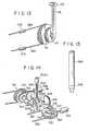
- Figs. 10 to 12show a major part of an endoscope as a fourth embodiment of the present invention.
- a bending operation lever 140made of solid material with a knob 141 at the free end thereof is coaxially and rotatably mounted through a shaft 142 to a spur gear 40 in mesh with a worm gear 44.
- the coiled spring 144is wound around the periphery of the shaft 142 fixed to the lever 140.
- the spring 144is fixed at one end to the spur gear 40 and at the other end to the lever 140.
- the lever 140is turned from a neutral position shown in Fig. 5 to either direction of an arrow 112 or 113, resisting a strength of stability of the spring 144.
- a resistor member 146 like an arcuate stripis provided at a given location on the side wall of the spur gear 40 in opposition to the lever 140.
- a contact bar 148disposed facing the resistor member 146, contacts at the L-shaped tip with the resistor member 146.
- the resistor member 146 and the contact member 148make up a potentiometer 150 in the control circuit 151 of Fig. 12.
- the remaining arrangement of the present embodimentis substantially the same as those of the other embodiments.
- the lever 140is at a neutral position by means of the coiled spring 144.
- the contact member 148 in contact with the resistor member 146 projecting from the lever 140is electrically connected to the resistor member 146 at the center position of the resistor member 146, as shown in Fig. 12. Under this condition, an input voltage applied to the amplifier 80 is zero.
- the contact member 148When the lever 140 is rotated resisting a strength of stability in one of the two opposite directions, the contact member 148, together with the lever 140, slides over the surface of the resistor member 146 toward one side. For example, the lever 140 is turned in the direction of an arrow 112, a positive voltage is applied to the amplifier 80. The motor 140 rotates forward and the insertion section 14 is bent upward. When the lever 140 is further turned in the same direction, the contact member 142 slides on the resistor member 146. A positive input voltage to the amplifier 80 raises. The output torque of the motor 48 increases to more greatly bent the insertion section upwardly.
- the present embodiment thus arrangedmay attain the useful effects comparable with those of the other embodiments.
- the pressure sensing elements 102 and 104 for detecting the operating force applied to the lever 66are mounted to the knob 100 attached to the lever 66.
- the pressure sensing elementsmay be attached to proper locations of the angulation wires 38a and 38b wound around the drum 36, as shown in Fig. 13. In this case, the pressure sensing elements are used for detecting the force applied to the wires.
- the flexible tube 19 of the insertion section 14is bent upward or downward. It is evident that the bending direction of the flexible tube may be up and down, and right and left.
- a ball member 300is provided at the bottom end of the operation lever 302. The ball member 300 is fitted in a spherical bearing 304 so as to allow the bending operation lever 302 to be turned in every direction.
- a couple of rotating members 306 and 308which are rotatable in the directions orthogonal to each other, are provided around the base portion of the lever 302.
- the rotating members 306 and 308are rotatably supported by shafts 310 and 308, which are arranged along the rotating members, respectively.
- the rotating members 306 and 308have elongated holes 306h and 308h extending along the shafts, respectively.
- the bending operation lever 302is passed through these holes.
- the shaft 310 of the rotating member 306 rotating in the back and forth directionis coupled with the rotating shaft 42 in the bending mechanism 34, through an intermediate gear 314, as in the first embodiment (Fig. 1).
- the shaft 312 of the rotating member 313 rotatable in the right and left directionsis coupled with the rotating shaft 322 of the drum 320 for bending the flexible tube in the right and left directions, through the intermediate gears 316 and 318.
- the gear 324is mounted to the gear 322 which is further in mesh with a warm gear 326 driven by the motor 328.
- Wires 330 and 332 for bending the flexible tube in the right and left directionsare wound around the drum 320.
- Resistor wire gauges 334 and 336 like those of the first embodimentare respectively attached to the side wall of the operation lever 302 facing the back and forth directions and the side wall of the lever facing the right and left directions.
- the flexible tube 19 of the insertion section 14(Fig. 1) is bent by driving the motors 48 and 328 by the signals derived from the resistor wire gauges 334 and 336.
- the releasing mechanism as shown in Fig. 2is also assembled into the present embodiment: Accordingly, when the motors 48 and 328 are trouble, the bending operation may easily be done by means of the bending operation lever 302. For more easy operation of the lever 302, it is preferable to use an auxiliary lever 340 provided with a hole into which the knob 302k of the operation lever 302 is fitted when the auxiliary lever is used, as shown in Fig. 15.
- the bending operating sectionis not necessary provided in the main body of the endoscope. It may be provided in the light source unit. Alternatively, it may be constructed in a separate unit for remotely controlling the bending operation of the insertion section 14.
Landscapes
- Life Sciences & Earth Sciences (AREA)
- Health & Medical Sciences (AREA)
- Surgery (AREA)
- Engineering & Computer Science (AREA)
- Biophysics (AREA)
- Medical Informatics (AREA)
- Nuclear Medicine, Radiotherapy & Molecular Imaging (AREA)
- Optics & Photonics (AREA)
- Pathology (AREA)
- Radiology & Medical Imaging (AREA)
- Veterinary Medicine (AREA)
- Biomedical Technology (AREA)
- Heart & Thoracic Surgery (AREA)
- Physics & Mathematics (AREA)
- Molecular Biology (AREA)
- Animal Behavior & Ethology (AREA)
- General Health & Medical Sciences (AREA)
- Public Health (AREA)
- Mechanical Engineering (AREA)
- Endoscopes (AREA)
- Instruments For Viewing The Inside Of Hollow Bodies (AREA)
Description
- The present invention relates to an endoscope system, and more particularly, to an endoscope system with an electric bending mechanism for electrically bending an insertion section.
- In a practical use of an endoscope, which is designed for specific mechanical purposes, the insertion section of the endoscope is directly inserted into a coeliac cavity of a living body, such as the stomach, intestines and the like. In bending the insertion section of the endoscope in the coeliac cavity, great care must be taken so as not to impair the coelum. To this end, a subtle and precise control of the motor drive strictly according to the wishes of the operator is required for the bending operation of the endoscope insertion section. Further required is to accurately know an actual direction and an actual amount of the bending of the insertion section inserted and now present in the coelum. Otherwise, the distal end of the insertion section is excessively and uncontrollably bent to possibly impair or, more adversely, break the inner wall of the coelum.
- From DE-A-29 51 764 an endoscope is known according to the pre-characterizing parts of claims 1, 5 or 7. This known endoscope is capable of bending its insertion section automatically by detecting differences in brightness between the inner wall of the body cavity and the space inside the cavity and thus it is possible to insert the insertion section into a body cavity wherein the tip of the insertion section automatically follows even a complicated curvature, e.g. of an intestine. Since endoscopic surgery is carried out inside the body of a living person, great care must be taken so as not to touch and possibly impair body tissue. To this end, a subtile and precise control of the motor drive strictly according to the wishes of the operator is required for the bending operation of the endoscopes insertion section. Also very necessary and strictly required is to accurately known the actual direction and the actual amount of the bending of the insertion section inserted and being present in the body cavity. Otherwise, the distal end of the insertion section is excessively and uncontrollably bent to possibly impair or - in the worst case - to break the inner wall of the body cavity. With the endoscope system according to DE-A-2 951 764 it is possible to bend the insertion section also by manual operation, but the operator bending the insertion section by hand is not aware of direction and actual amount of the bending degree, so that the aforementioned danger of possible impair of body tissue will occur.
- It is therefore an object of the present invention to provide an endoscope apparatus with a motor- driven bending mechanism which may reliably and accurately control the bending operation of its insertion section in quick response to the commands of an operator, whereby the operator is always aware of the actual direction and the actual amount of the bending degree, thus ensuring the safety of the living body into which the endoscope insertion section is inserted.
- The solution of this object is achieved by the characterizing features of claim 1, 5 or 7.
- According to the invention there is provided an endoscope apparatus being provided with an electric bending mechanism which is constructed such that the pressure applied to a resilient lever member by the operator is detected, and, in response to the magnitude of the pressure, the supply of electric energy to a bending motor is controlled. The lever and a drum are mechanically connected by gears and the lever operating amount detecting means, such as a distortion gauge, which detects the amount of pressure, is attached to this lever member. The manual pressure applied by the operator to the lever is detected by the gauge to thereby determine the rotation of the motor which bends the insertion section. The basic idea of the present invention is now the fact that as the insertion section is being bent, the corresponding drive of the motor is applied to the lever in such a way that - provided the operator does not apply further pressure to the lever - the elastic deformation of the lever is decreased.
- When the elastic deformation of the lever' becomes substantially zero, the deflection of the gauge also becomes zero and the supply of electricity to the motor is automatically stopped. (If, after this, the operator continues to operate the lever, the aforementioned operation will be repeated.) With this kind of mechanism, it is possible to automatically prevent further bending of the insertion section after it has been accurately bent by the amount corresponding to the amount the lever is actually operated. In order to carry out this bending operation, the operator needs only to move the lever by the desired amount and no separate operation, such as pressing a stop button is required.
- In order to change the direction of bending the operator just has to change the direction of operation of the lever member. So, it is also possible for the operator to see the actual direction and the actual amount of the bending by simply looking at the lever.
- The present invention is best understood by reference to the accompanying drawings, in which:
- Fig. 1 is a perspective view of an overall endoscope system which is a first embodiment of the present invention;
- Fig. 2 illustrates a structure of the peripheral portion of a motor provided in the endoscope system of Fig. 1;
- Fig. 3 is a circuit diagram of a control circuit for effecting a bending operation of an insertion section of the endoscope apparatus of Fig. 1;
- Fig. 4 is a perspective view of a major portion of an endoscope apparatus which is a second embodiment according to the present invention;
- Fig. 5 is a circuit diagram of a bending operation control circuit used in the endoscope of Fig. 4;
- Fig. 6 shows a perspective view of a partial structure containing an operation lever portion and its periphery portion, which is provided for effecting a bending operation of the insertion section in an operating section of an endoscope system as a third embodiment of the present invention;
- Fig. 7 is a circuit diagram of a bending operation control circuit containing the operation lever section of Fig. 6;
- Fig. 8 is an explanatory diagram illustrating a modification of the operation lever section of Fig. 7;
- Fig. 9 is a circuit diagram of a bending operation control circuit including the operation lever section of Fig. 8;
- Fig. 10 is a perspective view of an operation lever section including a potentiometer provided in an operating section of an endoscope system which is a fourth embodiment of the present invention;
- Fig. 11 is a perspective, exploded view illustrating in detail the structure of the operation lever section of Fig. 10;
- Fig. 12 is a circuit diagram illustrating a bending operation control circuit including the lever section of Fig. 10;
- Fig. 13 shows a perspective view of a modification of a bending operation lever of the embodiment shown in Figs. 4 and 5;
- Fig. 14 is a perspective view of the bending operation lever section of the embodiment shown in Figs. 1 to 3, which may be turned in every direction; and
- Fig. 15 is a perspective view of an auxiliary lever applied to the operation lever knob of Fig. 14 for improving operability in a manual operation of the operation lever.
- Referring now to Fig. 1, an endoscope system includes an
endoscope apparatus 10 and alight source apparatus 12. Theendoscope system 10 is comprised of aninsertion section 14 to be directly inserted into the coeliac cavity of a living body, a main body section or anoperating section 16 mechanically coupled to theinsertion section 14 and having a variety of switches (not shown), and anocular section 18 mounted to theoperating section 16. Theinsertion section 14 includes aflexible tube 19 bendable in a desired direction, and anend section 20 with a known structure mounted to the free end of thetube 19, which has a window (not shown) for allowing the passage of light rays and contains therein anobjective lens 22. Alight guide 24 using a bundle of optical fibers for transmitting light rays containing the data under observation is inserted into theinsertion section 14 and theoperating section 16, and extends at one end into theend section 20. In theend section 20, the one end of thelight guide 24 is positioned close to theobjective lens 22. Thelight guide 24 is further passed through a code coupled with theoperation section 16. This code is known as a light guide code or a universal code by those skilled in the art. Aconnector 27 of theuniversal code 26 is removably connected to thelight source apparatus 12 in a known manner. The other end of thelight guide 24 extending through theuniversal code 26 is positioned facing a light source, or alamp 28, in alight source apparatus 12 when thecode 26 is coupled with thelight source apparatus 12 through theconnector 27. Further, the positioning of the other end of thelight guide 24 is made in such a way that it may effectively receive the light rays emitted from thelamp 28. - An
image guide 30 for transmitting the reflected light from the inner surface of the coelom to which light rays are projected through the window of theend section 20 is formed of a bundle of optical fibers. Theimage guide 30 is passed through theinsertion section 14 and theoperation section 16 to extend into theocular section 18. In theocular section 18, theimage guide 30 is positioned at one end close to anobjective lens 32. Since the optical fibers forming thelight guide 24 and theimage guide 30 are made of flexible light transmitting material, the optical fibers may properly bend with the bending of theflexible tube 19 in theinsertion section 14. - The
operating section 16 of the endoscope contains a mechanism for an operator such as a doctor to remotely control the bending of theflexible tube 19 for changing the direction of theend section 20 in the coeliac cavity, such as the stomach or intestines, for diagnosing, inspecting or treating the patient. Thebending control mechanism 34 includes a continuous groove on the peripheral surface of the mechanism per se and adrum 36 freely rotatable in the forward or reverse direction. A wire 38 is wound around the groove of thedrum 36. Wires (angulation wires) 38a and 38b are led through theoperating section 16 and theinsertion section 14, and the ends thereof are fixed to theend section 20. With rotation of thedrum 36, theangulation wires flexible tube 19 and to change theend section 20 in a desired direction. - A
gear 40 is fixed to ashaft 42 of thedrum 36. Thegear 40 is in mesh with aworm gear 44 mounted to a rotatingshaft 46 of theelectric motor 48. Accordingly, thedrum 36 rotates selectively forwardly or backwardly with the rotation of themotor 48. Thus, theflexible tube 19 may be bent in a desired direction by the combination of thegear drum 36 and the wire 38, which is driven by a rotating torque of themotor 48. - The peripheral portion of the
motor 48 shown in Fig. 1 is illustrated in detail in Fig. 2. Themotor 48 is fixed to asupport plate 50 mounted rotatably in thedirection 54 through apin 52 at a given location in theoperating section 16. Anoperation lever 56 partially projecting outside the operatingsection 16 is formed integral with thesupport plate 10. Theconcave portions 58a and 58b are formed in the inner side wall of theoperation lever 56. A resilient member 60 engages with either of theconcave portions 58a and 58b. The resilient member 60 includes a hollowedtubular case 62, acoiled spring 64 fixed in thecase 62, and aball 68 fixed to the free end of thespring 64. Theball 68 is always energized by the spring to resiliently engage either of theconcave portions 58a and 58b. Amotor support plate 50 is located at a position (normal state) as indicated by a continuous line in Fig. 2, or at a position (operating state) as indicated by a dotted line, by normally operating thelever 56. In a normal state, theworm gear 44 mounted to themotor 48 fixed to thesupport plate 50, as illustrated by a continuous line, is in mesh with aspur gear 40 fixed to thedrum 36. A rotating power from themotor 48 may accordingly be transmitted to thedrum 36. When an operator pulls thelever 56, thesupport plate 50 is positioned in an operating state as indicated by a dash-dot line. Thegears - Returning to Fig. 1, a
lever 66 for the bending operation is fixedly mounted at the bottom part to therotating shaft 42 of thedrum 36. The bendingoperation lever 66 is made of relatively solid resilient material. When an operator manually applies a force to thelever 66, it is bent to some extent, resisting its resilient force in the longitudinal direction of theendoscope 10. Aknob 68 is fixed to the free end of theoperation lever 66. Theknob 68 protrudes outward from the operatingsection 16 of the endoscope system. A pressure-sensitive member such as apiezoelectric rubber 70 is attached to one of the two side walls of thecurved operation lever 66, which are substantially normal to the rotation or a curved direction. The piezoelectric rubber 70 (also called a resistor wire distortion gauge) changes its resistance according to a compression stress or a tension stress applied to therubber 70 by a manual bending of theoperation lever 66. Thus, thepiezoelectric rubber 70 serves as a detector for detecting the amount of operating force applied to thelever 66. - Fig. 3 shows an
electric circuit 69 for driving and controlling themotor 48 of acontrol section 71, preferably housed in thelight source apparatus 12 of Fig. 1. The resistorline distortion gauge 70, together withresistors 72 to 74, make up a knownbridge circuit 76. Two input terminals of thebridge circuit 76 are connected to aDC power source 78, as is well known. One of the input terminals of thebridge circuit 76 is connected to one of the input terminals of adifferential amplifier 80 and the other input terminal of thebridge circuit 76 is connected to a first terminal of themotor 48. The output terminal of theamplifier 80 is connected in series through aresistor 82 to the base electrodes of anNPN type transistor 84 and aPNP type transistor 86 to form abuffer circuit 88. The emitter electrodes of theconnected transistors motor 48. The emitter electrodes are also connected through aresistor 90 to the other input terminal of theamplifier 80 which is connected to the other output terminal of thebridge circuit 76 through aresistor 92. The first terminal of themotor 48 is connected to a negative terminal of aDC power source 94 and a positive terminal of aDC power source 96. A positive terminal of aDC power source 94 is connected to a collector electrode of theNPN transistor 84 and theamplifier 80. The negative terminal of theDC power source 96 is connected to the collector electrode of thePNP transistor 96 and theamplifier 80. - The operation of the endoscope system thus arranged, i.e., the first embodiment of the present invention, will now be described. When the bending
operation lever 66 of theendoscope system 10 is not operated, no external force is applied to thelever 66. The resistance of the resistorwire distortion gauge 70 at this time balances thebridge circuit 76 in the operation. Accordingly, thebridge circuit 76 produces no output voltage. - When an operator operates the
knob 68 coupled with the bendingoperation lever 66 for bending theflexible tube 19 of the insertion section, thelever 66 is bent. As the result of the knob operation, the compression stress of the tension stress is applied to thedistortion gauge 70, thereby changing the resistance of thedistortion gauge 70. A potential difference corresponding to that resistance change appears between the output terminals of thebridge circuit 76. The voltage corresponding to the potential difference is amplified by theamplifier 80 and is supplied to thebuffer circuit 88 through theresistor 82. To be more specific, when the operator pulls theknob 68 to his side (toward the ocular section 18), thelever 66 is bent toward theocular section 18 under the applied external force. Accordingly, thedistortion gauge 70 is slightly stretched by the tension to increase the resistance of thegauge 70. At this time, a positive potential corresponding to a resistance change of the gauge is generated at the output terminal of thebridge circuit 76. Accordingly, a positive amplified signal is generated from theamplifier 80. The positive potential signal is applied to the base electrodes of thetransistors buffer circuit 88. At this time, theNPN transistor 84 is conductive while thePNP transistor 86 is nonconductive. With this circuit connection, the electric power from theDC power source 94 is supplied through theconductive transistor 84 to themotor 48. As a result, themotor 48 is rotated forward. The drive power from the forwardrotating motor 48 is transmitted to thedrum 36 through thegears drum 36 rotates to wind up theangulation wire 38a and to bend theflexible tube 19 upward. - With the bending of the
tube 19, the rotation of thedrum 36 progresses and thelever 66, together with the rotatingshaft 42 of thedrum 36, turns progressively toward theocular section 18. During the course of the turning of thelever 66, when the force applied to theknob 68 is stopped, thelever 66 is released from its bending state after a fixed time lag (from the stoppage of the application of the force to the knob). Finally, the tension exerted on thedistortion gauge 70 becomes zero. At this time, the output voltage from thebridge circuit 76 is zero. The twotransistors buffer circuit 88 are shut off and themotor 48 automatically stops. - During the period when the rotation of the
drum 36 progresses with the bending operation of thetube 19, and thelever 66 and the rotating axis of thedrum 36 as well turn toward theocular section 18, if the operator continuously operates theknob 68, thelever 66 is further bent. Therefore, thebridge circuit 76 continuously produces a positive voltage. The positive voltage produced drives themotor 48 through thebuffer circuit 88. The motor keeps its rotation in the same direction. Theflexible tube 19 is further bent. In this condition, if the operator pulls theknob 68 further, an output voltage of thebridge circuit 76 further increases. A signal level of the detection signal produced from the amplifier also further increases. Themotor 48 rotates forward with a large torque to more forcibly bend theflexible tube 19. - Conversely, when the operator pushes the
knob 68 away from theocular section 18, thedistortion gauge 70 attached to thelever 66 is compressed. With compression of thegauge 70, the resistance of thegauge 70 decreases to cause thebridge circuit 76 to produce a negative voltage at one of the output terminals of thebridge circuit 76. Therefore, the detection signal produced from theamplifier 88 has a negative potential level and thePNP type transistor 86 contained in thebuffer circuit 88 is conductive. As a result, theDC power source 96 feeds a current to themotor 48 thereby rotating themotor 48. In this case, the direction of the rotation of the motor is opposite to that of the above-mentioned case, since the polarity of the current fed to the motor is opposite to that of the current in the above-mentioned case. With the reverse rotation of themotor 48, thedrum 36 winds up thewire 38b to bend theflexible tube 19 downwardly. - As seen from the foregoing description, the first embodiment of the present invention may automatically bend the
flexible tube 19 of theinsertion section 14 strictly according to the operation of theknob 68. A pressure-sensing characteristic of the pressure-sensing element 70 used as a distortion gauge is highly sensitive. Further, a control circuit used has a response characteristic comparable to the pressure-sensing characteristic. Therefore, the endoscope system according to the present invention may easily effect a subtle bending of the insertion section according to the needs of the operator. Therefore, the insertion section eliminates the uncontrollable bending operation. Therefore, there is no danger of damaging the inner wall of the coeliac cavity of a living body. Thus, the endoscope system of the present invention is quite safe when it is applied for inspecting the coelom. - When the
motor 48 and/or the control circuit of Fig. 3 malfunction during the course of use, it is very dangerous to pull out theinsertion section 14 from the coeliac cavity while theflexible tube 19 is left bent. In such a situation, however, when the endoscope system of the present invention is used, the motordrive release lever 56 is operated to remove theworm gear 44 from thespur gear 40. That is, the bending operation mode of the endoscope may easily be changed from a motor drive mode to a manual operation mode. Therefore, the danger mentioned above may be avoided. The safety of the endoscope system of the present invention is thus further enhanced. - Referring to Figs. 4 and 5, there is shown a major part of a second embodiment of an endoscope according to the present invention. Like or equivalent portions in the figures of the drawings are designated by like symbols used in the drawings of the first embodiment, for simplicity.
- In Fig. 4, a
knob 100 mounted at the free end of the bendingoperation lever 66 is provided with two surfaces slanting toward theocular section 18 and theinsertion section 14 of theendoscope 10.Piezoelectric rubber pieces control circuit 105 containing these piezoelectricpressure rubber pieces pieces common junction 106. One end of thepressure sensor 102 is coupled with a positive terminal of aDC power source 94 at a given voltage. One end of theother pressure sensor 104 is connected to a negative terminal of the otherDC power source 96 at the same voltage. The remaining circuit arrangement is similar to that of Fig. 3. - According to the second embodiment thus arranged, no extenal force is applied to the
piezoelectric rubber pieces knob 100 is not operated. Under this condition, in the control circuit shown in Fig. 5, the voltage drops across thepieces common junction 106 is substantially 0 V. No signal is produced from theamplifier 80. Twotransistors buffer circuit 88 are turned off so no electric power is supplied to themotor 86. The motor is at standstill. - For the bending operation of the
flexible tube 19, theknob 100 is pulled by or turned toward the operator, i.e. theocular section 18, for example. At this time, most of the force is applied to firstpiezoelectric rubber 102. Thepressure sensor element 102 decreases its resistance according to the force applied. In the control circuit shown in Fig. 5, a positive voltage appears at thecommon junction 106 and is applied to one-of the input terminals of theamplifier 80. Theamplifier 80 produces an amplified detection signal of positive potential which is in turn applied to thebuffer circuit 88. Upon receipt of the detection signal, theNPN type transistor 84 is conductive, while thePNP transistor 86 is turned off. A positive current flows from theDC power source 94 into themotor 48. Themotor 48 rotates forward. The subsequent operation is almost the same as that of the first embodiment. The forward rotation of themotor 48 bends theinsertion section 14 upward. If the application of the operating force applied to theknob 100 is discontinued, the potential at thecommon junction 106 in the control circuit shown in Fig. 5 is immediately returned to zero. Thus themotor 48 stops. - For bending the
insertion section 14 downward, theknob 100 is pushed away from theocular section 18. At this time, the resistance of thesecond pressure sensor 104 is decreased. The potential at thejunction 106 of the control circuit of Fig. 5 is negative and theamplifier 80 produces an amplified detection signal with negative polarity. The negative detection signal turns off thePNP type transistor 84 and turns on thePNP type transistor 86. TheDC power source 96 feeds a reverse current to themotor 48 through the conductingtransistor 86. Themotor 48 rotates in reverse. Subsequently, thedrum 36 rotates in reverse as in the case of the reverse rotation of the motor in the first embodiment. Theinsertion section 14 is bent downward. - Also, the second embodiment as mentioned above may obtain effects similar to those obtained by the first embodiment. While the progressive bending of the
insertion section 14, thelever 66 gradually turns with the rotatingshaft 42 mounted to therotating drum 36. A position of theknob 100 fixed to thelever 66 on theoperating section 16 shifts linearly. An amount of the bending of theinsertion section 14 may be quantitatively known on the basis of the degree of movement of theknob 100. - In Figs. 6 and 7, there are schematically shown a bending operation lever and its related portion, and a control circuit for the lever, which are applied for a third embodiment of an endoscope system according to the present invention. The remaining arrangement is substantially the same as those of the above-mentioned embodiments.
- In Fig. 6, a
lever support plate 110 is fixed to therotating shaft 42 of thedrum 36. Theplate 110 rotates integrally with the rotatingshaft 42. The bendingoperation lever 114 is rotatably or swing- ably mounted at the base thereof on theplate 110. Thelever 114 may turn in the direction of anarrow lever 114 is pulled in opposite directions by resilient members, for example,coiled springs lever 114, it is set at a neutral position, as shown in Fig. 6. A pair of contact pins 120 and 122 made of resilient material are provided on theplate 110, while being located on both sides of thelever 114. Thelever 114 at the neutral position equally divides a line connecting the contact pins 120 and 122. An electrode made of conductive material is attached to the portion of thelever 114 where thelever 114 is in contact with the contact pins 120 and 122. The pair ofpins lever electrode 124 equivalently made up a couple ofswitches control circuit 129 of Fig. 7. - A pair of
stopper members plate 110, with alever 114 interposed therebetween. Thestopper members lever 114 which is defined by the contact pins 120 and 122. Accordingly, thelever 114 is in contact with thestopper members lever electrode 124 contacts thecontact pin stopper 130 of 132 prevents the lever from further turning. - In the third embodiment thus arranged, an operator turns the
lever 114 in the direction of anarrow 112 in Fig. 6 until thelever 114 is in contact with thepin 120. Theswitch 126 is equivalently closed in the circuit shown in Fig. 7. At this time, as in the second embodiment, a positive current is fed from theDC power source 94 to themotor 48. Themotor 48 rotates forward. Thedrum 36 also rotates forward to wind up the wire 38 and to bend theinsertion section 14 upward. Theplate 110 mounted to therotating shaft 42 of thedrum 36 is rotated clockwise during the bending operation of theinsertion section 14, and rotates with thedrum 36 in a unit manner. When theplate 110 rotates over a fixed angle, thecontact pin 120 substantially departs from thelever electrode 124. At this time, theswitch 126 in the Fig. 7 circuit is opened. The result is that the power supply to themotor 48 is automatically stopped and themotor 48 is stopped. When thelever 14 is turned at a fixed angle and held as it is, the motor stops at the time that theinsertion section 14 is bent to a degree of the inclination angle of thelever 114. Theinsertion section 14 also stops its bending operation. If an operator progressively turns thelever 114, theinsertion section 14 is progressively bent. The amount of actual bending of the insertion section may be known from an inclination angle of thelever 114. In the present embodiment, the switches in the control circuit of Fig. 7 are made up of the contact pins 120 and 122, and thelever electrode 124. These switches may of course be substituted by any other suitable switches using piezoelectric rubber, and the like. - Figs. 8 and 9 schematically show a modification of the third embodiment of the present invention. Three pairs of
piezoelectric rubber pieces switch section 138, are provided on thelever support plate 110, sandwiching thelever 114. A first pair of thepiezoelectric rubber pieces lever 114 at a neutral position. A second pair of thepiezoelectric rubber pieces piezoelectric rubber pieces piezoelectric rubber pieces piezoelectric rubber pieces lever 114 is turned in the direction of anarrow 112, for example, thelever 114 first contacts thepiezoelectric rubber piece 130, and then thepiezoelectric rubber pieces - In the
control circuit 139 of Fig. 9, each pair of the piezoelectric rubber pieces are series-connected to each other, and three pairs of the piezoelectric rubber pieces are connected to one another in parallel. These pairs of thepiezoelectric rubber pieces 130 to 135 are inserted between a positive terminal of theDC power source 94 and a negative terminal of theDC power source 96. The remaining arrangement is substantially the same as those of the other embodiments. - In the endoscope shown in Figs. 8 and 9, it is assumed that an operator turns the bending
operation lever 114 in the direction of anarrow 112. In this case, only thepiezoelectric rubber piece 130 of the first pair of thepiezoelectric rubber pieces lever 114 to decrease its resistance. A positive voltage given by the decreased resistance is applied to theamplifier 80. Themotor 48 forwardly rotates in a similar manner to that of the above-mentioned embodiments to bend theinsertion section 14. Then, thelever 114 is further turned in the direction of anarrow 112. Thepiezoelectric rubber piece 132 of the second pair of the piezoelectric rubber pieces, together with therubber piece 130 is also pushed by thelever 114 to decrease its resistance. A higher positive voltage given by the further decreased resistance is applied to theamplifier 80 to increase an output torque of themotor 48. Subsequently, when thelever 114 is still further forcibly turned, therubber piece 134 is pushed together with the other tworubber pieces amplifier 80 to maximize the output torque of themotor 48. Thus, as the turn of thelever 114 is greater, the output torque of themotor 48 is larger and the bending speed increases. Accordingly, the output torque of themotor 48 may subtly be adjusted by changing the operating force applied to the operatinglever 114. And the bending speed of the output torque of themotor 48 may be changed in the same way. As a consequence, it is possible to realize a bending operation of the insertion section of the endoscope which is quick and accurate, and follows strictly the will of the operator. - Figs. 10 to 12 show a major part of an endoscope as a fourth embodiment of the present invention. In the present embodiment, a bending
operation lever 140 made of solid material with aknob 141 at the free end thereof is coaxially and rotatably mounted through ashaft 142 to aspur gear 40 in mesh with aworm gear 44. Thecoiled spring 144 is wound around the periphery of theshaft 142 fixed to thelever 140. Thespring 144 is fixed at one end to thespur gear 40 and at the other end to thelever 140. Thelever 140 is turned from a neutral position shown in Fig. 5 to either direction of anarrow spring 144. Aresistor member 146 like an arcuate strip is provided at a given location on the side wall of thespur gear 40 in opposition to thelever 140. Acontact bar 148, disposed facing theresistor member 146, contacts at the L-shaped tip with theresistor member 146. Theresistor member 146 and thecontact member 148 make up apotentiometer 150 in thecontrol circuit 151 of Fig. 12. The remaining arrangement of the present embodiment is substantially the same as those of the other embodiments. - In the endoscope incorporating such a potentiometer, the
lever 140 is at a neutral position by means of thecoiled spring 144. At the neutral position, thecontact member 148 in contact with theresistor member 146 projecting from thelever 140 is electrically connected to theresistor member 146 at the center position of theresistor member 146, as shown in Fig. 12. Under this condition, an input voltage applied to theamplifier 80 is zero. - When the
lever 140 is rotated resisting a strength of stability in one of the two opposite directions, thecontact member 148, together with thelever 140, slides over the surface of theresistor member 146 toward one side. For example, thelever 140 is turned in the direction of anarrow 112, a positive voltage is applied to theamplifier 80. Themotor 140 rotates forward and theinsertion section 14 is bent upward. When thelever 140 is further turned in the same direction, thecontact member 142 slides on theresistor member 146. A positive input voltage to theamplifier 80 raises. The output torque of themotor 48 increases to more greatly bent the insertion section upwardly. The present embodiment thus arranged may attain the useful effects comparable with those of the other embodiments. - Although the present invention has been shown and described with respect to particular embodiments, nevertheless, various changes and modifications are possible which are obvious to a person skilled in the art. For example, in the second embodiment of the endoscope shown in Figs. 4 and 5, the
pressure sensing elements lever 66 are mounted to theknob 100 attached to thelever 66. The pressure sensing elements may be attached to proper locations of theangulation wires drum 36, as shown in Fig. 13. In this case, the pressure sensing elements are used for detecting the force applied to the wires. - In the embodiment, shown in Figs. 1 to 3, the
flexible tube 19 of theinsertion section 14 is bent upward or downward. It is evident that the bending direction of the flexible tube may be up and down, and right and left. A major part of an embodiment of an endoscope in which theflexible tube 19 are bendable in various directions, as just mentioned, is illustrated in Figs. 14 and 15. In - the present embodiment, aball member 300 is provided at the bottom end of theoperation lever 302. Theball member 300 is fitted in aspherical bearing 304 so as to allow thebending operation lever 302 to be turned in every direction. A couple ofrotating members lever 302. The rotatingmembers shafts members holes 306h and 308h extending along the shafts, respectively. The bendingoperation lever 302 is passed through these holes. Theshaft 310 of the rotatingmember 306 rotating in the back and forth direction is coupled with the rotatingshaft 42 in thebending mechanism 34, through anintermediate gear 314, as in the first embodiment (Fig. 1). The shaft 312 of the rotatingmember 313 rotatable in the right and left directions is coupled with therotating shaft 322 of thedrum 320 for bending the flexible tube in the right and left directions, through theintermediate gears gear 324 is mounted to thegear 322 which is further in mesh with awarm gear 326 driven by the motor 328.Wires drum 320. Resistor wire gauges 334 and 336 like those of the first embodiment are respectively attached to the side wall of theoperation lever 302 facing the back and forth directions and the side wall of the lever facing the right and left directions. Theflexible tube 19 of the insertion section 14 (Fig. 1) is bent by driving themotors 48 and 328 by the signals derived from the resistor wire gauges 334 and 336. - The releasing mechanism as shown in Fig. 2 is also assembled into the present embodiment: Accordingly, when the
motors 48 and 328 are trouble, the bending operation may easily be done by means of the bendingoperation lever 302. For more easy operation of thelever 302, it is preferable to use an auxiliary lever 340 provided with a hole into which theknob 302k of theoperation lever 302 is fitted when the auxiliary lever is used, as shown in Fig. 15. - Additionally, the bending operating section is not necessary provided in the main body of the endoscope. It may be provided in the light source unit. Alternatively, it may be constructed in a separate unit for remotely controlling the bending operation of the
insertion section 14.
Claims (9)
Priority Applications (1)
| Application Number | Priority Date | Filing Date | Title |
|---|---|---|---|
| AT82109478TATE29655T1 (en) | 1981-10-15 | 1982-10-13 | ENDOSCOPE SYSTEM WITH ELECTRICALLY CONTROLLED BENDING. |
Applications Claiming Priority (6)
| Application Number | Priority Date | Filing Date | Title |
|---|---|---|---|
| JP164678/81 | 1981-10-15 | ||
| JP56164678AJPS5865132A (en) | 1981-10-15 | 1981-10-15 | Endoscope |
| JP56167594AJPS5869521A (en) | 1981-10-20 | 1981-10-20 | Endoscope |
| JP167594/81 | 1981-10-20 | ||
| JP176236/81 | 1981-11-02 | ||
| JP56176236AJPS5878635A (en) | 1981-11-02 | 1981-11-02 | Endoscope apparatus |
Publications (3)
| Publication Number | Publication Date |
|---|---|
| EP0077526A2 EP0077526A2 (en) | 1983-04-27 |
| EP0077526A3 EP0077526A3 (en) | 1984-05-02 |
| EP0077526B1true EP0077526B1 (en) | 1987-09-16 |
Family
ID=27322368
Family Applications (1)
| Application Number | Title | Priority Date | Filing Date |
|---|---|---|---|
| EP82109478AExpiredEP0077526B1 (en) | 1981-10-15 | 1982-10-13 | Endoscope system with an electric bending mechanism |
Country Status (3)
| Country | Link |
|---|---|
| US (1) | US4499895A (en) |
| EP (1) | EP0077526B1 (en) |
| DE (1) | DE3277287D1 (en) |
Families Citing this family (624)
| Publication number | Priority date | Publication date | Assignee | Title |
|---|---|---|---|---|
| EP0078017B1 (en)* | 1981-10-22 | 1988-03-30 | Olympus Optical Co., Ltd. | Endoscope apparatus with motor-driven bending mechanism |
| JPS5878639A (en)* | 1981-11-04 | 1983-05-12 | オリンパス光学工業株式会社 | Endoscope |
| JPS6148350A (en)* | 1984-08-15 | 1986-03-10 | オリンパス光学工業株式会社 | Medical laser apparatus |
| US4721099A (en)* | 1985-10-30 | 1988-01-26 | Kabushiki Kaisha Machida Seisakusho | Operating mechanism for bendable section of endoscope |
| JPH0336321Y2 (en)* | 1986-04-04 | 1991-08-01 | ||
| US4688555A (en)* | 1986-04-25 | 1987-08-25 | Circon Corporation | Endoscope with cable compensating mechanism |
| DE3734979A1 (en)* | 1986-10-16 | 1988-04-28 | Olympus Optical Co | ENDOSCOPE |
| US5060632A (en)* | 1989-09-05 | 1991-10-29 | Olympus Optical Co., Ltd. | Endoscope apparatus |
| US5125395A (en)* | 1990-09-12 | 1992-06-30 | Adair Edwin Lloyd | Deflectable sheath for optical catheter |
| US5217453A (en)* | 1991-03-18 | 1993-06-08 | Wilk Peter J | Automated surgical system and apparatus |
| US5217003A (en)* | 1991-03-18 | 1993-06-08 | Wilk Peter J | Automated surgical system and apparatus |
| JP3063784B2 (en)* | 1991-03-26 | 2000-07-12 | オリンパス光学工業株式会社 | Endoscope device |
| US5197649A (en)* | 1991-10-29 | 1993-03-30 | The Trustees Of Columbia University In The City Of New York | Gastrointestinal endoscoptic stapler |
| EP0543738A1 (en)* | 1991-11-22 | 1993-05-26 | Welch Allyn, Inc. | Detachable servo actuated insertion tube for borescope or endoscope |
| US5469840A (en)* | 1991-12-10 | 1995-11-28 | Olympus Optical, Ltd. | Electromotive warping type endoscope with velocity control |
| US5325845A (en)* | 1992-06-08 | 1994-07-05 | Adair Edwin Lloyd | Steerable sheath for use with selected removable optical catheter |
| US5549542A (en)* | 1992-11-17 | 1996-08-27 | Life Medical Technologies, Inc. | Deflectable endoscope |
| US5472017A (en)* | 1992-11-17 | 1995-12-05 | Life Medical Technologies, Inc. | Deflectable catheter |
| DE4496456D2 (en)* | 1993-08-30 | 1997-07-31 | Stm Medtech Starnberg | Endoscope with a movable front end area |
| KR0176025B1 (en)* | 1996-07-11 | 1999-04-01 | 최진호 | Product sales apparatus and method of vending machine |
| KR980010890A (en)* | 1996-07-13 | 1998-04-30 | 최진호 | Time display device and method of vending machine |
| US6221070B1 (en) | 1996-10-18 | 2001-04-24 | Irvine Biomedical, Inc. | Steerable ablation catheter system having disposable shaft |
| WO1999033392A1 (en) | 1997-12-29 | 1999-07-08 | Falko Skrabal | Deformable probe with automatic detection of the position of the probe |
| US7775972B2 (en)* | 1998-02-24 | 2010-08-17 | Hansen Medical, Inc. | Flexible instrument |
| US5967997A (en)* | 1998-04-30 | 1999-10-19 | Symbiosis Corporation | Endoscopic surgical instrument with deflectable and rotatable distal end |
| US6464711B1 (en)* | 1999-03-19 | 2002-10-15 | Medtronic Xomed, Inc. | Articulating mechanism for steerable surgical cutting instruments |
| US6716233B1 (en)* | 1999-06-02 | 2004-04-06 | Power Medical Interventions, Inc. | Electromechanical driver and remote surgical instrument attachment having computer assisted control capabilities |
| US7032798B2 (en) | 1999-06-02 | 2006-04-25 | Power Medical Interventions, Inc. | Electro-mechanical surgical device |
| US8229549B2 (en)* | 2004-07-09 | 2012-07-24 | Tyco Healthcare Group Lp | Surgical imaging device |
| US6981941B2 (en)* | 1999-06-02 | 2006-01-03 | Power Medical Interventions | Electro-mechanical surgical device |
| US6264087B1 (en) | 1999-07-12 | 2001-07-24 | Powermed, Inc. | Expanding parallel jaw device for use with an electromechanical driver device |
| US6517565B1 (en) | 1999-06-02 | 2003-02-11 | Power Medical Interventions, Inc. | Carriage assembly for controlling a steering wire steering mechanism within a flexible shaft |
| US8025199B2 (en) | 2004-02-23 | 2011-09-27 | Tyco Healthcare Group Lp | Surgical cutting and stapling device |
| US6793652B1 (en) | 1999-06-02 | 2004-09-21 | Power Medical Interventions, Inc. | Electro-mechanical surgical device |
| US6315184B1 (en)* | 1999-06-02 | 2001-11-13 | Powermed, Inc. | Stapling device for use with an electromechanical driver device for use with anastomosing, stapling, and resecting instruments |
| US7695485B2 (en) | 2001-11-30 | 2010-04-13 | Power Medical Interventions, Llc | Surgical device |
| US7951071B2 (en) | 1999-06-02 | 2011-05-31 | Tyco Healthcare Group Lp | Moisture-detecting shaft for use with an electro-mechanical surgical device |
| US6443973B1 (en) | 1999-06-02 | 2002-09-03 | Power Medical Interventions, Inc. | Electromechanical driver device for use with anastomosing, stapling, and resecting instruments |
| US6491201B1 (en) | 2000-02-22 | 2002-12-10 | Power Medical Interventions, Inc. | Fluid delivery mechanism for use with anastomosing, stapling, and resecting instruments |
| US6348061B1 (en) | 2000-02-22 | 2002-02-19 | Powermed, Inc. | Vessel and lumen expander attachment for use with an electromechanical driver device |
| US6533157B1 (en) | 2000-02-22 | 2003-03-18 | Power Medical Interventions, Inc. | Tissue stapling attachment for use with an electromechanical driver device |
| US8016855B2 (en)* | 2002-01-08 | 2011-09-13 | Tyco Healthcare Group Lp | Surgical device |
| US6488197B1 (en) | 2000-02-22 | 2002-12-03 | Power Medical Interventions, Inc. | Fluid delivery device for use with anastomosing resecting and stapling instruments |
| US6569086B2 (en)* | 2000-03-27 | 2003-05-27 | Olympus Optical Co., Ltd. | Controllable bending endoscope |
| US8888688B2 (en) | 2000-04-03 | 2014-11-18 | Intuitive Surgical Operations, Inc. | Connector device for a controllable instrument |
| US6984203B2 (en)* | 2000-04-03 | 2006-01-10 | Neoguide Systems, Inc. | Endoscope with adjacently positioned guiding apparatus |
| US8517923B2 (en)* | 2000-04-03 | 2013-08-27 | Intuitive Surgical Operations, Inc. | Apparatus and methods for facilitating treatment of tissue via improved delivery of energy based and non-energy based modalities |
| US6837846B2 (en)* | 2000-04-03 | 2005-01-04 | Neo Guide Systems, Inc. | Endoscope having a guide tube |
| US6858005B2 (en) | 2000-04-03 | 2005-02-22 | Neo Guide Systems, Inc. | Tendon-driven endoscope and methods of insertion |
| US6974411B2 (en)* | 2000-04-03 | 2005-12-13 | Neoguide Systems, Inc. | Endoscope with single step guiding apparatus |
| US6610007B2 (en)* | 2000-04-03 | 2003-08-26 | Neoguide Systems, Inc. | Steerable segmented endoscope and method of insertion |
| WO2005018428A2 (en)* | 2000-04-03 | 2005-03-03 | Neoguide Systems, Inc. | Activated polymer articulated instruments and methods of insertion |
| US6800056B2 (en) | 2000-04-03 | 2004-10-05 | Neoguide Systems, Inc. | Endoscope with guiding apparatus |
| US6468203B2 (en) | 2000-04-03 | 2002-10-22 | Neoguide Systems, Inc. | Steerable endoscope and improved method of insertion |
| US6982849B2 (en)* | 2000-09-14 | 2006-01-03 | Samsung Electronics Co., Ltd. | Method and apparatus for providing positional information on a disk |
| US6724553B2 (en) | 2001-03-26 | 2004-04-20 | Samsung Electronics Co., Ltd. | Method and apparatus for generating the optimum read timing for read and write offset of a magneto resistive head |
| DE10214174B4 (en)* | 2001-03-30 | 2008-08-28 | Fujinon Corp. | Curvature actuating device for an endoscope |
| US6522933B2 (en) | 2001-03-30 | 2003-02-18 | Biosense, Webster, Inc. | Steerable catheter with a control handle having a pulley mechanism |
| JP4617059B2 (en) | 2001-04-20 | 2011-01-19 | パワー メディカル インターベンションズ, エルエルシー | Imaging device |
| US6793622B2 (en) | 2001-09-05 | 2004-09-21 | Olympus Optical Co., Ltd. | Electric bending endoscope |
| KR100468764B1 (en) | 2001-09-13 | 2005-01-29 | 삼성전자주식회사 | Method and apparatus for providing positional information on a disk |
| US6835173B2 (en)* | 2001-10-05 | 2004-12-28 | Scimed Life Systems, Inc. | Robotic endoscope |
| US6770027B2 (en) | 2001-10-05 | 2004-08-03 | Scimed Life Systems, Inc. | Robotic endoscope with wireless interface |
| US6791780B2 (en) | 2001-10-15 | 2004-09-14 | Samsung Electronics Co., Inc. | Method and apparatus for providing write current optimization |
| US7035031B2 (en)* | 2001-11-26 | 2006-04-25 | Samsung Electronics Co., Ltd. | Installation of heater into hard disk drive to improve reliability and performance at low temperature |
| US9113878B2 (en) | 2002-01-08 | 2015-08-25 | Covidien Lp | Pinion clip for right angle linear cutter |
| US20030167007A1 (en)* | 2002-01-09 | 2003-09-04 | Amir Belson | Apparatus and method for spectroscopic examination of the colon |
| CA2472207A1 (en) | 2002-01-09 | 2003-07-24 | Neoguide Systems, Inc. | Apparatus and method for endoscopic colectomy |
| EP1478263B1 (en) | 2002-01-30 | 2011-03-09 | Tyco Healthcare Group LP | Surgical imaging device |
| CA2489727C (en) | 2002-06-14 | 2011-04-26 | Power Medical Interventions, Inc. | Surgical device |
| US20040059191A1 (en)* | 2002-06-17 | 2004-03-25 | Robert Krupa | Mechanical steering mechanism for borescopes, endoscopes, catheters, guide tubes, and working tools |
| US6679836B2 (en) | 2002-06-21 | 2004-01-20 | Scimed Life Systems, Inc. | Universal programmable guide catheter |
| AU2003275336A1 (en)* | 2002-09-30 | 2004-04-23 | Power Medical Interventions, Inc. | Self-contained sterilizable surgical system |
| US20040068161A1 (en)* | 2002-10-02 | 2004-04-08 | Couvillon Lucien Alfred | Thrombolysis catheter |
| US8882657B2 (en)* | 2003-03-07 | 2014-11-11 | Intuitive Surgical Operations, Inc. | Instrument having radio frequency identification systems and methods for use |
| US20040193014A1 (en)* | 2003-03-26 | 2004-09-30 | Olympus Optical Co., Ltd. | Electric bending endoscope |
| US7591783B2 (en)* | 2003-04-01 | 2009-09-22 | Boston Scientific Scimed, Inc. | Articulation joint for video endoscope |
| US20040199052A1 (en) | 2003-04-01 | 2004-10-07 | Scimed Life Systems, Inc. | Endoscopic imaging system |
| US20050245789A1 (en)* | 2003-04-01 | 2005-11-03 | Boston Scientific Scimed, Inc. | Fluid manifold for endoscope system |
| US8118732B2 (en) | 2003-04-01 | 2012-02-21 | Boston Scientific Scimed, Inc. | Force feedback control system for video endoscope |
| US7578786B2 (en)* | 2003-04-01 | 2009-08-25 | Boston Scientific Scimed, Inc. | Video endoscope |
| US20050222499A1 (en)* | 2003-04-01 | 2005-10-06 | Banik Michael S | Interface for video endoscope system |
| US20070084897A1 (en) | 2003-05-20 | 2007-04-19 | Shelton Frederick E Iv | Articulating surgical stapling instrument incorporating a two-piece e-beam firing mechanism |
| US9060770B2 (en) | 2003-05-20 | 2015-06-23 | Ethicon Endo-Surgery, Inc. | Robotically-driven surgical instrument with E-beam driver |
| US20050171467A1 (en)* | 2004-01-30 | 2005-08-04 | Jaime Landman | Multiple function surgical device |
| US7744619B2 (en)* | 2004-02-24 | 2010-06-29 | Boston Scientific Scimed, Inc. | Rotatable catheter assembly |
| US7922740B2 (en) | 2004-02-24 | 2011-04-12 | Boston Scientific Scimed, Inc. | Rotatable catheter assembly |
| US8215531B2 (en) | 2004-07-28 | 2012-07-10 | Ethicon Endo-Surgery, Inc. | Surgical stapling instrument having a medical substance dispenser |
| US11998198B2 (en) | 2004-07-28 | 2024-06-04 | Cilag Gmbh International | Surgical stapling instrument incorporating a two-piece E-beam firing mechanism |
| US9072535B2 (en) | 2011-05-27 | 2015-07-07 | Ethicon Endo-Surgery, Inc. | Surgical stapling instruments with rotatable staple deployment arrangements |
| US11890012B2 (en) | 2004-07-28 | 2024-02-06 | Cilag Gmbh International | Staple cartridge comprising cartridge body and attached support |
| US7597662B2 (en) | 2004-09-30 | 2009-10-06 | Boston Scientific Scimed, Inc. | Multi-fluid delivery system |
| US20060069310A1 (en)* | 2004-09-30 | 2006-03-30 | Couvillon Lucien A Jr | Programmable brake control system for use in a medical device |
| US20060068360A1 (en)* | 2004-09-30 | 2006-03-30 | Scimed Life Systems, Inc. | Single use fluid reservoir for an endoscope |
| JP2008514363A (en) | 2004-09-30 | 2008-05-08 | ボストン サイエンティフィック リミテッド | Multifunctional endoscope system for use in electrosurgical applications |
| US7479106B2 (en) | 2004-09-30 | 2009-01-20 | Boston Scientific Scimed, Inc. | Automated control of irrigation and aspiration in a single-use endoscope |
| WO2006039522A2 (en)* | 2004-09-30 | 2006-04-13 | Boston Scientific Scimed, Inc. | Adapter for use with digital imaging medical device |
| US7241263B2 (en)* | 2004-09-30 | 2007-07-10 | Scimed Life Systems, Inc. | Selectively rotatable shaft coupler |
| US8083671B2 (en) | 2004-09-30 | 2011-12-27 | Boston Scientific Scimed, Inc. | Fluid delivery system for use with an endoscope |
| US20060069305A1 (en)* | 2004-09-30 | 2006-03-30 | Boston Scientific Scimed, Inc. | Device with enhanced indication of use and prevention of re-use |
| EP1799096A2 (en)* | 2004-09-30 | 2007-06-27 | Boston Scientific Scimed, Inc. | System and method of obstruction removal |
| US20060235457A1 (en)* | 2005-04-15 | 2006-10-19 | Amir Belson | Instruments having a rigidizable external working channel |
| US7846107B2 (en) | 2005-05-13 | 2010-12-07 | Boston Scientific Scimed, Inc. | Endoscopic apparatus with integrated multiple biopsy device |
| US8097003B2 (en) | 2005-05-13 | 2012-01-17 | Boston Scientific Scimed, Inc. | Endoscopic apparatus with integrated variceal ligation device |
| US7618413B2 (en) | 2005-06-22 | 2009-11-17 | Boston Scientific Scimed, Inc. | Medical device control system |
| US8052597B2 (en)* | 2005-08-30 | 2011-11-08 | Boston Scientific Scimed, Inc. | Method for forming an endoscope articulation joint |
| US7673781B2 (en) | 2005-08-31 | 2010-03-09 | Ethicon Endo-Surgery, Inc. | Surgical stapling device with staple driver that supports multiple wire diameter staples |
| US11484312B2 (en) | 2005-08-31 | 2022-11-01 | Cilag Gmbh International | Staple cartridge comprising a staple driver arrangement |
| US11246590B2 (en) | 2005-08-31 | 2022-02-15 | Cilag Gmbh International | Staple cartridge including staple drivers having different unfired heights |
| US7934630B2 (en) | 2005-08-31 | 2011-05-03 | Ethicon Endo-Surgery, Inc. | Staple cartridges for forming staples having differing formed staple heights |
| US7669746B2 (en) | 2005-08-31 | 2010-03-02 | Ethicon Endo-Surgery, Inc. | Staple cartridges for forming staples having differing formed staple heights |
| US9237891B2 (en) | 2005-08-31 | 2016-01-19 | Ethicon Endo-Surgery, Inc. | Robotically-controlled surgical stapling devices that produce formed staples having different lengths |
| US10159482B2 (en) | 2005-08-31 | 2018-12-25 | Ethicon Llc | Fastener cartridge assembly comprising a fixed anvil and different staple heights |
| JP2009507617A (en)* | 2005-09-14 | 2009-02-26 | ネオガイド システムズ, インコーポレイテッド | Method and apparatus for performing transluminal and other operations |
| US20070106317A1 (en)* | 2005-11-09 | 2007-05-10 | Shelton Frederick E Iv | Hydraulically and electrically actuated articulation joints for surgical instruments |
| US20070161857A1 (en) | 2005-11-22 | 2007-07-12 | Neoguide Systems, Inc. | Method of determining the shape of a bendable instrument |
| US8083879B2 (en)* | 2005-11-23 | 2011-12-27 | Intuitive Surgical Operations, Inc. | Non-metallic, multi-strand control cable for steerable instruments |
| US20070167676A1 (en)* | 2006-01-13 | 2007-07-19 | Olympus Medical Systems Corp. | Overtube and medical procedure via natural orifice using the same |
| US20080255422A1 (en)* | 2006-01-13 | 2008-10-16 | Olympus Medical Systems Corp. | Medical device |
| US8728121B2 (en)* | 2006-01-13 | 2014-05-20 | Olympus Medical Systems Corp. | Puncture needle and medical procedure using puncture needle that is performed via natural orifice |
| US8721657B2 (en)* | 2006-01-13 | 2014-05-13 | Olympus Medical Systems Corp. | Medical instrument |
| US20070219411A1 (en)* | 2006-01-13 | 2007-09-20 | Olympus Medical Systems Corp. | Overtube and endoscopic treatment system |
| US7967759B2 (en) | 2006-01-19 | 2011-06-28 | Boston Scientific Scimed, Inc. | Endoscopic system with integrated patient respiratory status indicator |
| US7845537B2 (en) | 2006-01-31 | 2010-12-07 | Ethicon Endo-Surgery, Inc. | Surgical instrument having recording capabilities |
| US20120292367A1 (en) | 2006-01-31 | 2012-11-22 | Ethicon Endo-Surgery, Inc. | Robotically-controlled end effector |
| US11793518B2 (en) | 2006-01-31 | 2023-10-24 | Cilag Gmbh International | Powered surgical instruments with firing system lockout arrangements |
| US8708213B2 (en) | 2006-01-31 | 2014-04-29 | Ethicon Endo-Surgery, Inc. | Surgical instrument having a feedback system |
| US8186555B2 (en) | 2006-01-31 | 2012-05-29 | Ethicon Endo-Surgery, Inc. | Motor-driven surgical cutting and fastening instrument with mechanical closure system |
| US11278279B2 (en) | 2006-01-31 | 2022-03-22 | Cilag Gmbh International | Surgical instrument assembly |
| US20110295295A1 (en) | 2006-01-31 | 2011-12-01 | Ethicon Endo-Surgery, Inc. | Robotically-controlled surgical instrument having recording capabilities |
| US11224427B2 (en) | 2006-01-31 | 2022-01-18 | Cilag Gmbh International | Surgical stapling system including a console and retraction assembly |
| US9861359B2 (en) | 2006-01-31 | 2018-01-09 | Ethicon Llc | Powered surgical instruments with firing system lockout arrangements |
| US7753904B2 (en) | 2006-01-31 | 2010-07-13 | Ethicon Endo-Surgery, Inc. | Endoscopic surgical instrument with a handle that can articulate with respect to the shaft |
| US8820603B2 (en) | 2006-01-31 | 2014-09-02 | Ethicon Endo-Surgery, Inc. | Accessing data stored in a memory of a surgical instrument |
| US20110024477A1 (en) | 2009-02-06 | 2011-02-03 | Hall Steven G | Driven Surgical Stapler Improvements |
| US8236010B2 (en) | 2006-03-23 | 2012-08-07 | Ethicon Endo-Surgery, Inc. | Surgical fastener and cutter with mimicking end effector |
| US8992422B2 (en) | 2006-03-23 | 2015-03-31 | Ethicon Endo-Surgery, Inc. | Robotically-controlled endoscopic accessory channel |
| US8888684B2 (en)* | 2006-03-27 | 2014-11-18 | Boston Scientific Scimed, Inc. | Medical devices with local drug delivery capabilities |
| US7955255B2 (en)* | 2006-04-20 | 2011-06-07 | Boston Scientific Scimed, Inc. | Imaging assembly with transparent distal cap |
| US8202265B2 (en) | 2006-04-20 | 2012-06-19 | Boston Scientific Scimed, Inc. | Multiple lumen assembly for use in endoscopes or other medical devices |
| KR100764740B1 (en)* | 2006-05-16 | 2007-10-08 | 삼성전자주식회사 | Flash memory device and high voltage generating circuit for it |
| US8568299B2 (en) | 2006-05-19 | 2013-10-29 | Intuitive Surgical Operations, Inc. | Methods and apparatus for displaying three-dimensional orientation of a steerable distal tip of an endoscope |
| US8322455B2 (en) | 2006-06-27 | 2012-12-04 | Ethicon Endo-Surgery, Inc. | Manually driven surgical cutting and fastening instrument |
| US7506791B2 (en) | 2006-09-29 | 2009-03-24 | Ethicon Endo-Surgery, Inc. | Surgical stapling instrument with mechanical mechanism for limiting maximum tissue compression |
| US10568652B2 (en) | 2006-09-29 | 2020-02-25 | Ethicon Llc | Surgical staples having attached drivers of different heights and stapling instruments for deploying the same |
| US10130359B2 (en) | 2006-09-29 | 2018-11-20 | Ethicon Llc | Method for forming a staple |
| US11980366B2 (en) | 2006-10-03 | 2024-05-14 | Cilag Gmbh International | Surgical instrument |
| US9456877B2 (en) | 2006-12-01 | 2016-10-04 | Boston Scientific Scimed, Inc. | Direct drive instruments and methods of use |
| US11291441B2 (en) | 2007-01-10 | 2022-04-05 | Cilag Gmbh International | Surgical instrument with wireless communication between control unit and remote sensor |
| US8632535B2 (en) | 2007-01-10 | 2014-01-21 | Ethicon Endo-Surgery, Inc. | Interlock and surgical instrument including same |
| US8684253B2 (en) | 2007-01-10 | 2014-04-01 | Ethicon Endo-Surgery, Inc. | Surgical instrument with wireless communication between a control unit of a robotic system and remote sensor |
| US8652120B2 (en) | 2007-01-10 | 2014-02-18 | Ethicon Endo-Surgery, Inc. | Surgical instrument with wireless communication between control unit and sensor transponders |
| US20080169333A1 (en) | 2007-01-11 | 2008-07-17 | Shelton Frederick E | Surgical stapler end effector with tapered distal end |
| US11039836B2 (en) | 2007-01-11 | 2021-06-22 | Cilag Gmbh International | Staple cartridge for use with a surgical stapling instrument |
| US7673782B2 (en) | 2007-03-15 | 2010-03-09 | Ethicon Endo-Surgery, Inc. | Surgical stapling instrument having a releasable buttress material |
| US8893946B2 (en) | 2007-03-28 | 2014-11-25 | Ethicon Endo-Surgery, Inc. | Laparoscopic tissue thickness and clamp load measuring devices |
| US20080269556A1 (en)* | 2007-04-02 | 2008-10-30 | Jagasia Ashok A | Endoscope with flexible tip |
| US7708182B2 (en) | 2007-04-17 | 2010-05-04 | Tyco Healthcare Group Lp | Flexible endoluminal surgical instrument |
| JP5191164B2 (en)* | 2007-05-08 | 2013-04-24 | オリンパスメディカルシステムズ株式会社 | Medical equipment |
| EP3375479B1 (en) | 2007-05-18 | 2023-03-22 | Boston Scientific Scimed, Inc. | Medical drive systems |
| US8931682B2 (en) | 2007-06-04 | 2015-01-13 | Ethicon Endo-Surgery, Inc. | Robotically-controlled shaft based rotary drive systems for surgical instruments |
| US11564682B2 (en) | 2007-06-04 | 2023-01-31 | Cilag Gmbh International | Surgical stapler device |
| US8408439B2 (en) | 2007-06-22 | 2013-04-02 | Ethicon Endo-Surgery, Inc. | Surgical stapling instrument with an articulatable end effector |
| US7753245B2 (en) | 2007-06-22 | 2010-07-13 | Ethicon Endo-Surgery, Inc. | Surgical stapling instruments |
| US11849941B2 (en) | 2007-06-29 | 2023-12-26 | Cilag Gmbh International | Staple cartridge having staple cavities extending at a transverse angle relative to a longitudinal cartridge axis |
| GB2451498A (en)* | 2007-07-31 | 2009-02-04 | Prosurgics Ltd | A motorised manipulator that accommodates manual movement of a surgical instrument |
| EP2039284B1 (en)* | 2007-09-19 | 2011-05-25 | FUJIFILM Corporation | Endoscope |
| AU2008302043B2 (en)* | 2007-09-21 | 2013-06-27 | Covidien Lp | Surgical device |
| CN102793571B (en) | 2007-09-21 | 2014-12-17 | 柯惠Lp公司 | Surgical device |
| US9220398B2 (en) | 2007-10-11 | 2015-12-29 | Intuitive Surgical Operations, Inc. | System for managing Bowden cables in articulating instruments |
| US20090171161A1 (en)* | 2007-12-10 | 2009-07-02 | Usgi Medical, Inc. | Steerable endoscopic instruments |
| KR101583246B1 (en) | 2008-02-06 | 2016-01-12 | 인튜어티브 서지컬 오퍼레이션즈 인코포레이티드 | A segmented instrument having braking capabilities |
| US8561870B2 (en) | 2008-02-13 | 2013-10-22 | Ethicon Endo-Surgery, Inc. | Surgical stapling instrument |
| US7866527B2 (en) | 2008-02-14 | 2011-01-11 | Ethicon Endo-Surgery, Inc. | Surgical stapling apparatus with interlockable firing system |
| US8657174B2 (en) | 2008-02-14 | 2014-02-25 | Ethicon Endo-Surgery, Inc. | Motorized surgical cutting and fastening instrument having handle based power source |
| US11986183B2 (en) | 2008-02-14 | 2024-05-21 | Cilag Gmbh International | Surgical cutting and fastening instrument comprising a plurality of sensors to measure an electrical parameter |
| US8758391B2 (en) | 2008-02-14 | 2014-06-24 | Ethicon Endo-Surgery, Inc. | Interchangeable tools for surgical instruments |
| US9179912B2 (en) | 2008-02-14 | 2015-11-10 | Ethicon Endo-Surgery, Inc. | Robotically-controlled motorized surgical cutting and fastening instrument |
| US8573465B2 (en) | 2008-02-14 | 2013-11-05 | Ethicon Endo-Surgery, Inc. | Robotically-controlled surgical end effector system with rotary actuated closure systems |
| US7819298B2 (en) | 2008-02-14 | 2010-10-26 | Ethicon Endo-Surgery, Inc. | Surgical stapling apparatus with control features operable with one hand |
| JP5410110B2 (en) | 2008-02-14 | 2014-02-05 | エシコン・エンド−サージェリィ・インコーポレイテッド | Surgical cutting / fixing instrument with RF electrode |
| US8636736B2 (en) | 2008-02-14 | 2014-01-28 | Ethicon Endo-Surgery, Inc. | Motorized surgical cutting and fastening instrument |
| US9585657B2 (en) | 2008-02-15 | 2017-03-07 | Ethicon Endo-Surgery, Llc | Actuator for releasing a layer of material from a surgical end effector |
| US11272927B2 (en) | 2008-02-15 | 2022-03-15 | Cilag Gmbh International | Layer arrangements for surgical staple cartridges |
| US8182418B2 (en) | 2008-02-25 | 2012-05-22 | Intuitive Surgical Operations, Inc. | Systems and methods for articulating an elongate body |
| US20090240106A1 (en)* | 2008-03-05 | 2009-09-24 | Board Of Regents, The University Of Texas System | Endoscope With a Stimulating Electrode For Peripheral Nerve Blocks Under Direct Vision |
| US9986896B2 (en)* | 2008-03-05 | 2018-06-05 | The Board Of Regents Of The University Of Texas System | Disposable sheath designs for the stimulating endoscope and needle endoscopes having distal electrodes for nerve block under direct vision and methods for making and using same |
| US8133199B2 (en) | 2008-08-27 | 2012-03-13 | Boston Scientific Scimed, Inc. | Electroactive polymer activation system for a medical device |
| US7954686B2 (en) | 2008-09-19 | 2011-06-07 | Ethicon Endo-Surgery, Inc. | Surgical stapler with apparatus for adjusting staple height |
| PL3476312T3 (en) | 2008-09-19 | 2024-03-11 | Ethicon Llc | Surgical stapler with apparatus for adjusting staple height |
| US9005230B2 (en) | 2008-09-23 | 2015-04-14 | Ethicon Endo-Surgery, Inc. | Motorized surgical instrument |
| US9386983B2 (en) | 2008-09-23 | 2016-07-12 | Ethicon Endo-Surgery, Llc | Robotically-controlled motorized surgical instrument |
| US11648005B2 (en) | 2008-09-23 | 2023-05-16 | Cilag Gmbh International | Robotically-controlled motorized surgical instrument with an end effector |
| US8210411B2 (en) | 2008-09-23 | 2012-07-03 | Ethicon Endo-Surgery, Inc. | Motor-driven surgical cutting instrument |
| US8608045B2 (en) | 2008-10-10 | 2013-12-17 | Ethicon Endo-Sugery, Inc. | Powered surgical cutting and stapling apparatus with manually retractable firing system |
| US8517239B2 (en) | 2009-02-05 | 2013-08-27 | Ethicon Endo-Surgery, Inc. | Surgical stapling instrument comprising a magnetic element driver |
| US8453907B2 (en) | 2009-02-06 | 2013-06-04 | Ethicon Endo-Surgery, Inc. | Motor driven surgical fastener device with cutting member reversing mechanism |
| US8444036B2 (en) | 2009-02-06 | 2013-05-21 | Ethicon Endo-Surgery, Inc. | Motor driven surgical fastener device with mechanisms for adjusting a tissue gap within the end effector |
| RU2525225C2 (en) | 2009-02-06 | 2014-08-10 | Этикон Эндо-Серджери, Инк. | Improvement of drive surgical suturing instrument |
| CN101995917B (en)* | 2009-08-20 | 2012-03-14 | 鸿富锦精密工业(深圳)有限公司 | Electronic device with operating rod |
| US8220688B2 (en) | 2009-12-24 | 2012-07-17 | Ethicon Endo-Surgery, Inc. | Motor-driven surgical cutting instrument with electric actuator directional control assembly |
| US8851354B2 (en) | 2009-12-24 | 2014-10-07 | Ethicon Endo-Surgery, Inc. | Surgical cutting instrument that analyzes tissue thickness |
| US8783543B2 (en) | 2010-07-30 | 2014-07-22 | Ethicon Endo-Surgery, Inc. | Tissue acquisition arrangements and methods for surgical stapling devices |
| JP5675223B2 (en)* | 2010-08-31 | 2015-02-25 | 富士フイルム株式会社 | Endoscope and hardness adjustment device |
| US11925354B2 (en) | 2010-09-30 | 2024-03-12 | Cilag Gmbh International | Staple cartridge comprising staples positioned within a compressible portion thereof |
| US9629814B2 (en) | 2010-09-30 | 2017-04-25 | Ethicon Endo-Surgery, Llc | Tissue thickness compensator configured to redistribute compressive forces |
| US11812965B2 (en) | 2010-09-30 | 2023-11-14 | Cilag Gmbh International | Layer of material for a surgical end effector |
| US9016542B2 (en) | 2010-09-30 | 2015-04-28 | Ethicon Endo-Surgery, Inc. | Staple cartridge comprising compressible distortion resistant components |
| US9232941B2 (en) | 2010-09-30 | 2016-01-12 | Ethicon Endo-Surgery, Inc. | Tissue thickness compensator comprising a reservoir |
| US9301753B2 (en) | 2010-09-30 | 2016-04-05 | Ethicon Endo-Surgery, Llc | Expandable tissue thickness compensator |
| US9314246B2 (en) | 2010-09-30 | 2016-04-19 | Ethicon Endo-Surgery, Llc | Tissue stapler having a thickness compensator incorporating an anti-inflammatory agent |
| US12213666B2 (en) | 2010-09-30 | 2025-02-04 | Cilag Gmbh International | Tissue thickness compensator comprising layers |
| US11298125B2 (en) | 2010-09-30 | 2022-04-12 | Cilag Gmbh International | Tissue stapler having a thickness compensator |
| US10945731B2 (en) | 2010-09-30 | 2021-03-16 | Ethicon Llc | Tissue thickness compensator comprising controlled release and expansion |
| US9364233B2 (en) | 2010-09-30 | 2016-06-14 | Ethicon Endo-Surgery, Llc | Tissue thickness compensators for circular surgical staplers |
| US9351730B2 (en) | 2011-04-29 | 2016-05-31 | Ethicon Endo-Surgery, Llc | Tissue thickness compensator comprising channels |
| US9220501B2 (en) | 2010-09-30 | 2015-12-29 | Ethicon Endo-Surgery, Inc. | Tissue thickness compensators |
| US9055941B2 (en) | 2011-09-23 | 2015-06-16 | Ethicon Endo-Surgery, Inc. | Staple cartridge including collapsible deck |
| US9277919B2 (en) | 2010-09-30 | 2016-03-08 | Ethicon Endo-Surgery, Llc | Tissue thickness compensator comprising fibers to produce a resilient load |
| US9307989B2 (en) | 2012-03-28 | 2016-04-12 | Ethicon Endo-Surgery, Llc | Tissue stapler having a thickness compensator incorportating a hydrophobic agent |
| US9788834B2 (en) | 2010-09-30 | 2017-10-17 | Ethicon Llc | Layer comprising deployable attachment members |
| RU2013119928A (en) | 2010-09-30 | 2014-11-10 | Этикон Эндо-Серджери, Инк. | A STAPLING SYSTEM CONTAINING A RETAINING MATRIX AND A LEVELING MATRIX |
| US9332974B2 (en) | 2010-09-30 | 2016-05-10 | Ethicon Endo-Surgery, Llc | Layered tissue thickness compensator |
| US9386988B2 (en) | 2010-09-30 | 2016-07-12 | Ethicon End-Surgery, LLC | Retainer assembly including a tissue thickness compensator |
| US8695866B2 (en) | 2010-10-01 | 2014-04-15 | Ethicon Endo-Surgery, Inc. | Surgical instrument having a power control circuit |
| AU2012250197B2 (en) | 2011-04-29 | 2017-08-10 | Ethicon Endo-Surgery, Inc. | Staple cartridge comprising staples positioned within a compressible portion thereof |
| US11207064B2 (en) | 2011-05-27 | 2021-12-28 | Cilag Gmbh International | Automated end effector component reloading system for use with a robotic system |
| US20130012958A1 (en) | 2011-07-08 | 2013-01-10 | Stanislaw Marczyk | Surgical Device with Articulation and Wrist Rotation |
| US9050084B2 (en) | 2011-09-23 | 2015-06-09 | Ethicon Endo-Surgery, Inc. | Staple cartridge including collapsible deck arrangement |
| US9044230B2 (en) | 2012-02-13 | 2015-06-02 | Ethicon Endo-Surgery, Inc. | Surgical cutting and fastening instrument with apparatus for determining cartridge and firing motion status |
| MX358135B (en) | 2012-03-28 | 2018-08-06 | Ethicon Endo Surgery Inc | Tissue thickness compensator comprising a plurality of layers. |
| BR112014024098B1 (en) | 2012-03-28 | 2021-05-25 | Ethicon Endo-Surgery, Inc. | staple cartridge |
| JP6224070B2 (en) | 2012-03-28 | 2017-11-01 | エシコン・エンド−サージェリィ・インコーポレイテッドEthicon Endo−Surgery,Inc. | Retainer assembly including tissue thickness compensator |
| US9101358B2 (en) | 2012-06-15 | 2015-08-11 | Ethicon Endo-Surgery, Inc. | Articulatable surgical instrument comprising a firing drive |
| US9289256B2 (en) | 2012-06-28 | 2016-03-22 | Ethicon Endo-Surgery, Llc | Surgical end effectors having angled tissue-contacting surfaces |
| BR112014032776B1 (en) | 2012-06-28 | 2021-09-08 | Ethicon Endo-Surgery, Inc | SURGICAL INSTRUMENT SYSTEM AND SURGICAL KIT FOR USE WITH A SURGICAL INSTRUMENT SYSTEM |
| JP6290201B2 (en) | 2012-06-28 | 2018-03-07 | エシコン・エンド−サージェリィ・インコーポレイテッドEthicon Endo−Surgery,Inc. | Lockout for empty clip cartridge |
| US12383267B2 (en) | 2012-06-28 | 2025-08-12 | Cilag Gmbh International | Robotically powered surgical device with manually-actuatable reversing system |
| US20140001231A1 (en) | 2012-06-28 | 2014-01-02 | Ethicon Endo-Surgery, Inc. | Firing system lockout arrangements for surgical instruments |
| US11278284B2 (en) | 2012-06-28 | 2022-03-22 | Cilag Gmbh International | Rotary drive arrangements for surgical instruments |
| US9282974B2 (en) | 2012-06-28 | 2016-03-15 | Ethicon Endo-Surgery, Llc | Empty clip cartridge lockout |
| US9408606B2 (en) | 2012-06-28 | 2016-08-09 | Ethicon Endo-Surgery, Llc | Robotically powered surgical device with manually-actuatable reversing system |
| US20140005718A1 (en) | 2012-06-28 | 2014-01-02 | Ethicon Endo-Surgery, Inc. | Multi-functional powered surgical device with external dissection features |
| DE102012106755A1 (en) | 2012-07-25 | 2014-01-30 | Karl Storz Gmbh & Co. Kg | endoscope |
| DE102012110255A1 (en) | 2012-10-26 | 2014-04-30 | Karl Storz Gmbh & Co. Kg | Endoscopic instrument |
| DE102013101202A1 (en) | 2013-02-07 | 2014-08-07 | Karl Storz Gmbh & Co. Kg | Endoscopic instrument |
| US9386984B2 (en) | 2013-02-08 | 2016-07-12 | Ethicon Endo-Surgery, Llc | Staple cartridge comprising a releasable cover |
| US9468438B2 (en) | 2013-03-01 | 2016-10-18 | Eticon Endo-Surgery, LLC | Sensor straightened end effector during removal through trocar |
| RU2672520C2 (en) | 2013-03-01 | 2018-11-15 | Этикон Эндо-Серджери, Инк. | Hingedly turnable surgical instruments with conducting ways for signal transfer |
| BR112015021082B1 (en) | 2013-03-01 | 2022-05-10 | Ethicon Endo-Surgery, Inc | surgical instrument |
| US9657817B2 (en) | 2013-03-11 | 2017-05-23 | Boston Scientific Scimed, Inc. | Deflection mechanism |
| US9345481B2 (en) | 2013-03-13 | 2016-05-24 | Ethicon Endo-Surgery, Llc | Staple cartridge tissue thickness sensor system |
| US9629629B2 (en) | 2013-03-14 | 2017-04-25 | Ethicon Endo-Surgey, LLC | Control systems for surgical instruments |
| US9808244B2 (en) | 2013-03-14 | 2017-11-07 | Ethicon Llc | Sensor arrangements for absolute positioning system for surgical instruments |
| US9572577B2 (en) | 2013-03-27 | 2017-02-21 | Ethicon Endo-Surgery, Llc | Fastener cartridge comprising a tissue thickness compensator including openings therein |
| US9795384B2 (en) | 2013-03-27 | 2017-10-24 | Ethicon Llc | Fastener cartridge comprising a tissue thickness compensator and a gap setting element |
| US9332984B2 (en) | 2013-03-27 | 2016-05-10 | Ethicon Endo-Surgery, Llc | Fastener cartridge assemblies |
| BR112015026109B1 (en) | 2013-04-16 | 2022-02-22 | Ethicon Endo-Surgery, Inc | surgical instrument |
| US9826976B2 (en) | 2013-04-16 | 2017-11-28 | Ethicon Llc | Motor driven surgical instruments with lockable dual drive shafts |
| US9574644B2 (en) | 2013-05-30 | 2017-02-21 | Ethicon Endo-Surgery, Llc | Power module for use with a surgical instrument |
| WO2014203673A1 (en)* | 2013-06-20 | 2014-12-24 | オリンパスメディカルシステムズ株式会社 | Introduction device |
| US9629633B2 (en) | 2013-07-09 | 2017-04-25 | Covidien Lp | Surgical device, surgical adapters for use between surgical handle assembly and surgical loading units, and methods of use |
| US9775609B2 (en) | 2013-08-23 | 2017-10-03 | Ethicon Llc | Tamper proof circuit for surgical instrument battery pack |
| MX369362B (en) | 2013-08-23 | 2019-11-06 | Ethicon Endo Surgery Llc | Firing member retraction devices for powered surgical instruments. |
| KR102160753B1 (en) | 2013-09-13 | 2020-09-28 | 삼성전자주식회사 | Endoscope device |
| US20150173756A1 (en) | 2013-12-23 | 2015-06-25 | Ethicon Endo-Surgery, Inc. | Surgical cutting and stapling methods |
| US9839428B2 (en) | 2013-12-23 | 2017-12-12 | Ethicon Llc | Surgical cutting and stapling instruments with independent jaw control features |
| US9724092B2 (en) | 2013-12-23 | 2017-08-08 | Ethicon Llc | Modular surgical instruments |
| US20150173749A1 (en) | 2013-12-23 | 2015-06-25 | Ethicon Endo-Surgery, Inc. | Surgical staples and staple cartridges |
| US9962161B2 (en) | 2014-02-12 | 2018-05-08 | Ethicon Llc | Deliverable surgical instrument |
| US20140166724A1 (en) | 2014-02-24 | 2014-06-19 | Ethicon Endo-Surgery, Inc. | Staple cartridge including a barbed staple |
| JP6462004B2 (en) | 2014-02-24 | 2019-01-30 | エシコン エルエルシー | Fastening system with launcher lockout |
| US20150272580A1 (en) | 2014-03-26 | 2015-10-01 | Ethicon Endo-Surgery, Inc. | Verification of number of battery exchanges/procedure count |
| BR112016021943B1 (en) | 2014-03-26 | 2022-06-14 | Ethicon Endo-Surgery, Llc | SURGICAL INSTRUMENT FOR USE BY AN OPERATOR IN A SURGICAL PROCEDURE |
| US9913642B2 (en) | 2014-03-26 | 2018-03-13 | Ethicon Llc | Surgical instrument comprising a sensor system |
| US12232723B2 (en) | 2014-03-26 | 2025-02-25 | Cilag Gmbh International | Systems and methods for controlling a segmented circuit |
| US10013049B2 (en) | 2014-03-26 | 2018-07-03 | Ethicon Llc | Power management through sleep options of segmented circuit and wake up control |
| US10004497B2 (en) | 2014-03-26 | 2018-06-26 | Ethicon Llc | Interface systems for use with surgical instruments |
| CN106456176B (en) | 2014-04-16 | 2019-06-28 | 伊西康内外科有限责任公司 | Fastener Cartridge Including Extensions With Different Configurations |
| CN106456159B (en) | 2014-04-16 | 2019-03-08 | 伊西康内外科有限责任公司 | Fastener Cartridge Assembly and Nail Retainer Cover Arrangement |
| BR112016023825B1 (en) | 2014-04-16 | 2022-08-02 | Ethicon Endo-Surgery, Llc | STAPLE CARTRIDGE FOR USE WITH A SURGICAL STAPLER AND STAPLE CARTRIDGE FOR USE WITH A SURGICAL INSTRUMENT |
| US20150297225A1 (en) | 2014-04-16 | 2015-10-22 | Ethicon Endo-Surgery, Inc. | Fastener cartridges including extensions having different configurations |
| US10327764B2 (en) | 2014-09-26 | 2019-06-25 | Ethicon Llc | Method for creating a flexible staple line |
| US10470768B2 (en) | 2014-04-16 | 2019-11-12 | Ethicon Llc | Fastener cartridge including a layer attached thereto |
| US10045781B2 (en) | 2014-06-13 | 2018-08-14 | Ethicon Llc | Closure lockout systems for surgical instruments |
| US11311294B2 (en) | 2014-09-05 | 2022-04-26 | Cilag Gmbh International | Powered medical device including measurement of closure state of jaws |
| BR112017004361B1 (en) | 2014-09-05 | 2023-04-11 | Ethicon Llc | ELECTRONIC SYSTEM FOR A SURGICAL INSTRUMENT |
| US10135242B2 (en) | 2014-09-05 | 2018-11-20 | Ethicon Llc | Smart cartridge wake up operation and data retention |
| JP6667510B2 (en)* | 2014-09-09 | 2020-03-18 | インテュイティブ サージカル オペレーションズ, インコーポレイテッド | Flexible medical instruments |
| US10105142B2 (en) | 2014-09-18 | 2018-10-23 | Ethicon Llc | Surgical stapler with plurality of cutting elements |
| CN107427300B (en) | 2014-09-26 | 2020-12-04 | 伊西康有限责任公司 | Surgical suture buttresses and auxiliary materials |
| US11523821B2 (en) | 2014-09-26 | 2022-12-13 | Cilag Gmbh International | Method for creating a flexible staple line |
| US10076325B2 (en) | 2014-10-13 | 2018-09-18 | Ethicon Llc | Surgical stapling apparatus comprising a tissue stop |
| US9924944B2 (en) | 2014-10-16 | 2018-03-27 | Ethicon Llc | Staple cartridge comprising an adjunct material |
| US10517594B2 (en) | 2014-10-29 | 2019-12-31 | Ethicon Llc | Cartridge assemblies for surgical staplers |
| US11141153B2 (en) | 2014-10-29 | 2021-10-12 | Cilag Gmbh International | Staple cartridges comprising driver arrangements |
| US9844376B2 (en) | 2014-11-06 | 2017-12-19 | Ethicon Llc | Staple cartridge comprising a releasable adjunct material |
| US10736636B2 (en) | 2014-12-10 | 2020-08-11 | Ethicon Llc | Articulatable surgical instrument system |
| US10085748B2 (en) | 2014-12-18 | 2018-10-02 | Ethicon Llc | Locking arrangements for detachable shaft assemblies with articulatable surgical end effectors |
| MX389118B (en) | 2014-12-18 | 2025-03-20 | Ethicon Llc | SURGICAL INSTRUMENT WITH AN ANVIL THAT CAN BE SELECTIVELY MOVED ON A DISCRETE, NON-MOBILE AXIS RELATIVE TO A STAPLE CARTRIDGE. |
| US9844375B2 (en) | 2014-12-18 | 2017-12-19 | Ethicon Llc | Drive arrangements for articulatable surgical instruments |
| US9987000B2 (en) | 2014-12-18 | 2018-06-05 | Ethicon Llc | Surgical instrument assembly comprising a flexible articulation system |
| US9844374B2 (en) | 2014-12-18 | 2017-12-19 | Ethicon Llc | Surgical instrument systems comprising an articulatable end effector and means for adjusting the firing stroke of a firing member |
| US10188385B2 (en) | 2014-12-18 | 2019-01-29 | Ethicon Llc | Surgical instrument system comprising lockable systems |
| US10117649B2 (en) | 2014-12-18 | 2018-11-06 | Ethicon Llc | Surgical instrument assembly comprising a lockable articulation system |
| US9943309B2 (en) | 2014-12-18 | 2018-04-17 | Ethicon Llc | Surgical instruments with articulatable end effectors and movable firing beam support arrangements |
| US9993258B2 (en) | 2015-02-27 | 2018-06-12 | Ethicon Llc | Adaptable surgical instrument handle |
| US11154301B2 (en) | 2015-02-27 | 2021-10-26 | Cilag Gmbh International | Modular stapling assembly |
| US10159483B2 (en) | 2015-02-27 | 2018-12-25 | Ethicon Llc | Surgical apparatus configured to track an end-of-life parameter |
| US10180463B2 (en) | 2015-02-27 | 2019-01-15 | Ethicon Llc | Surgical apparatus configured to assess whether a performance parameter of the surgical apparatus is within an acceptable performance band |
| US10245033B2 (en) | 2015-03-06 | 2019-04-02 | Ethicon Llc | Surgical instrument comprising a lockable battery housing |
| US9808246B2 (en) | 2015-03-06 | 2017-11-07 | Ethicon Endo-Surgery, Llc | Method of operating a powered surgical instrument |
| US9993248B2 (en) | 2015-03-06 | 2018-06-12 | Ethicon Endo-Surgery, Llc | Smart sensors with local signal processing |
| JP2020121162A (en) | 2015-03-06 | 2020-08-13 | エシコン エルエルシーEthicon LLC | Time dependent evaluation of sensor data to determine stability element, creep element and viscoelastic element of measurement |
| US9901342B2 (en) | 2015-03-06 | 2018-02-27 | Ethicon Endo-Surgery, Llc | Signal and power communication system positioned on a rotatable shaft |
| US10441279B2 (en) | 2015-03-06 | 2019-10-15 | Ethicon Llc | Multiple level thresholds to modify operation of powered surgical instruments |
| US10045776B2 (en) | 2015-03-06 | 2018-08-14 | Ethicon Llc | Control techniques and sub-processor contained within modular shaft with select control processing from handle |
| US10617412B2 (en) | 2015-03-06 | 2020-04-14 | Ethicon Llc | System for detecting the mis-insertion of a staple cartridge into a surgical stapler |
| US9924961B2 (en) | 2015-03-06 | 2018-03-27 | Ethicon Endo-Surgery, Llc | Interactive feedback system for powered surgical instruments |
| US10687806B2 (en) | 2015-03-06 | 2020-06-23 | Ethicon Llc | Adaptive tissue compression techniques to adjust closure rates for multiple tissue types |
| US9895148B2 (en) | 2015-03-06 | 2018-02-20 | Ethicon Endo-Surgery, Llc | Monitoring speed control and precision incrementing of motor for powered surgical instruments |
| US10548504B2 (en) | 2015-03-06 | 2020-02-04 | Ethicon Llc | Overlaid multi sensor radio frequency (RF) electrode system to measure tissue compression |
| US10433844B2 (en) | 2015-03-31 | 2019-10-08 | Ethicon Llc | Surgical instrument with selectively disengageable threaded drive systems |
| JP6153692B2 (en)* | 2015-05-27 | 2017-06-28 | オリンパス株式会社 | Medical manipulator |
| US10154841B2 (en) | 2015-06-18 | 2018-12-18 | Ethicon Llc | Surgical stapling instruments with lockout arrangements for preventing firing system actuation when a cartridge is spent or missing |
| US10835249B2 (en) | 2015-08-17 | 2020-11-17 | Ethicon Llc | Implantable layers for a surgical instrument |
| MX2022009705A (en) | 2015-08-26 | 2022-11-07 | Ethicon Llc | Surgical staples comprising hardness variations for improved fastening of tissue. |
| MX2018002392A (en) | 2015-08-26 | 2018-08-01 | Ethicon Llc | Staple cartridge assembly comprising various tissue compression gaps and staple forming gaps. |
| RU2725081C2 (en) | 2015-08-26 | 2020-06-29 | ЭТИКОН ЭлЭлСи | Strips with surgical staples allowing the presence of staples with variable properties and providing simple loading of the cartridge |
| US10980538B2 (en) | 2015-08-26 | 2021-04-20 | Ethicon Llc | Surgical stapling configurations for curved and circular stapling instruments |
| MX2022006189A (en) | 2015-09-02 | 2022-06-16 | Ethicon Llc | Surgical staple configurations with camming surfaces located between portions supporting surgical staples. |
| US10238390B2 (en) | 2015-09-02 | 2019-03-26 | Ethicon Llc | Surgical staple cartridges with driver arrangements for establishing herringbone staple patterns |
| US10363036B2 (en) | 2015-09-23 | 2019-07-30 | Ethicon Llc | Surgical stapler having force-based motor control |
| US10105139B2 (en) | 2015-09-23 | 2018-10-23 | Ethicon Llc | Surgical stapler having downstream current-based motor control |
| US10085751B2 (en) | 2015-09-23 | 2018-10-02 | Ethicon Llc | Surgical stapler having temperature-based motor control |
| US10076326B2 (en) | 2015-09-23 | 2018-09-18 | Ethicon Llc | Surgical stapler having current mirror-based motor control |
| US10327769B2 (en) | 2015-09-23 | 2019-06-25 | Ethicon Llc | Surgical stapler having motor control based on a drive system component |
| US10238386B2 (en) | 2015-09-23 | 2019-03-26 | Ethicon Llc | Surgical stapler having motor control based on an electrical parameter related to a motor current |
| US10299878B2 (en) | 2015-09-25 | 2019-05-28 | Ethicon Llc | Implantable adjunct systems for determining adjunct skew |
| US11890015B2 (en) | 2015-09-30 | 2024-02-06 | Cilag Gmbh International | Compressible adjunct with crossing spacer fibers |
| US10478188B2 (en) | 2015-09-30 | 2019-11-19 | Ethicon Llc | Implantable layer comprising a constricted configuration |
| US10433846B2 (en) | 2015-09-30 | 2019-10-08 | Ethicon Llc | Compressible adjunct with crossing spacer fibers |
| US10980539B2 (en) | 2015-09-30 | 2021-04-20 | Ethicon Llc | Implantable adjunct comprising bonded layers |
| US10368865B2 (en) | 2015-12-30 | 2019-08-06 | Ethicon Llc | Mechanisms for compensating for drivetrain failure in powered surgical instruments |
| US10292704B2 (en) | 2015-12-30 | 2019-05-21 | Ethicon Llc | Mechanisms for compensating for battery pack failure in powered surgical instruments |
| US10265068B2 (en) | 2015-12-30 | 2019-04-23 | Ethicon Llc | Surgical instruments with separable motors and motor control circuits |
| US10413291B2 (en) | 2016-02-09 | 2019-09-17 | Ethicon Llc | Surgical instrument articulation mechanism with slotted secondary constraint |
| BR112018016098B1 (en) | 2016-02-09 | 2023-02-23 | Ethicon Llc | SURGICAL INSTRUMENT |
| US11213293B2 (en) | 2016-02-09 | 2022-01-04 | Cilag Gmbh International | Articulatable surgical instruments with single articulation link arrangements |
| US10258331B2 (en) | 2016-02-12 | 2019-04-16 | Ethicon Llc | Mechanisms for compensating for drivetrain failure in powered surgical instruments |
| US11224426B2 (en) | 2016-02-12 | 2022-01-18 | Cilag Gmbh International | Mechanisms for compensating for drivetrain failure in powered surgical instruments |
| US10448948B2 (en) | 2016-02-12 | 2019-10-22 | Ethicon Llc | Mechanisms for compensating for drivetrain failure in powered surgical instruments |
| US10617413B2 (en) | 2016-04-01 | 2020-04-14 | Ethicon Llc | Closure system arrangements for surgical cutting and stapling devices with separate and distinct firing shafts |
| US10413297B2 (en) | 2016-04-01 | 2019-09-17 | Ethicon Llc | Surgical stapling system configured to apply annular rows of staples having different heights |
| US10426467B2 (en) | 2016-04-15 | 2019-10-01 | Ethicon Llc | Surgical instrument with detection sensors |
| US11179150B2 (en) | 2016-04-15 | 2021-11-23 | Cilag Gmbh International | Systems and methods for controlling a surgical stapling and cutting instrument |
| US11607239B2 (en) | 2016-04-15 | 2023-03-21 | Cilag Gmbh International | Systems and methods for controlling a surgical stapling and cutting instrument |
| US10828028B2 (en) | 2016-04-15 | 2020-11-10 | Ethicon Llc | Surgical instrument with multiple program responses during a firing motion |
| US10405859B2 (en) | 2016-04-15 | 2019-09-10 | Ethicon Llc | Surgical instrument with adjustable stop/start control during a firing motion |
| US10357247B2 (en) | 2016-04-15 | 2019-07-23 | Ethicon Llc | Surgical instrument with multiple program responses during a firing motion |
| US10335145B2 (en) | 2016-04-15 | 2019-07-02 | Ethicon Llc | Modular surgical instrument with configurable operating mode |
| US10492783B2 (en) | 2016-04-15 | 2019-12-03 | Ethicon, Llc | Surgical instrument with improved stop/start control during a firing motion |
| US10456137B2 (en) | 2016-04-15 | 2019-10-29 | Ethicon Llc | Staple formation detection mechanisms |
| US20170296173A1 (en) | 2016-04-18 | 2017-10-19 | Ethicon Endo-Surgery, Llc | Method for operating a surgical instrument |
| US10363037B2 (en) | 2016-04-18 | 2019-07-30 | Ethicon Llc | Surgical instrument system comprising a magnetic lockout |
| US11317917B2 (en) | 2016-04-18 | 2022-05-03 | Cilag Gmbh International | Surgical stapling system comprising a lockable firing assembly |
| USD826405S1 (en) | 2016-06-24 | 2018-08-21 | Ethicon Llc | Surgical fastener |
| USD847989S1 (en) | 2016-06-24 | 2019-05-07 | Ethicon Llc | Surgical fastener cartridge |
| US10893863B2 (en) | 2016-06-24 | 2021-01-19 | Ethicon Llc | Staple cartridge comprising offset longitudinal staple rows |
| JP6980705B2 (en) | 2016-06-24 | 2021-12-15 | エシコン エルエルシーEthicon LLC | Stapling system for use with wire staples and punched staples |
| USD850617S1 (en) | 2016-06-24 | 2019-06-04 | Ethicon Llc | Surgical fastener cartridge |
| JP6957532B2 (en) | 2016-06-24 | 2021-11-02 | エシコン エルエルシーEthicon LLC | Staple cartridges including wire staples and punched staples |
| US10500000B2 (en) | 2016-08-16 | 2019-12-10 | Ethicon Llc | Surgical tool with manual control of end effector jaws |
| US10813638B2 (en) | 2016-12-21 | 2020-10-27 | Ethicon Llc | Surgical end effectors with expandable tissue stop arrangements |
| US10993715B2 (en) | 2016-12-21 | 2021-05-04 | Ethicon Llc | Staple cartridge comprising staples with different clamping breadths |
| CN110087565A (en) | 2016-12-21 | 2019-08-02 | 爱惜康有限责任公司 | Surgical stapling system |
| JP6983893B2 (en) | 2016-12-21 | 2021-12-17 | エシコン エルエルシーEthicon LLC | Lockout configuration for surgical end effectors and replaceable tool assemblies |
| US10485543B2 (en) | 2016-12-21 | 2019-11-26 | Ethicon Llc | Anvil having a knife slot width |
| US10758229B2 (en) | 2016-12-21 | 2020-09-01 | Ethicon Llc | Surgical instrument comprising improved jaw control |
| US20180168625A1 (en) | 2016-12-21 | 2018-06-21 | Ethicon Endo-Surgery, Llc | Surgical stapling instruments with smart staple cartridges |
| US10695055B2 (en) | 2016-12-21 | 2020-06-30 | Ethicon Llc | Firing assembly comprising a lockout |
| US20180168648A1 (en) | 2016-12-21 | 2018-06-21 | Ethicon Endo-Surgery, Llc | Durability features for end effectors and firing assemblies of surgical stapling instruments |
| US10582928B2 (en) | 2016-12-21 | 2020-03-10 | Ethicon Llc | Articulation lock arrangements for locking an end effector in an articulated position in response to actuation of a jaw closure system |
| US10973516B2 (en) | 2016-12-21 | 2021-04-13 | Ethicon Llc | Surgical end effectors and adaptable firing members therefor |
| US11090048B2 (en) | 2016-12-21 | 2021-08-17 | Cilag Gmbh International | Method for resetting a fuse of a surgical instrument shaft |
| US20180168615A1 (en) | 2016-12-21 | 2018-06-21 | Ethicon Endo-Surgery, Llc | Method of deforming staples from two different types of staple cartridges with the same surgical stapling instrument |
| US10980536B2 (en) | 2016-12-21 | 2021-04-20 | Ethicon Llc | No-cartridge and spent cartridge lockout arrangements for surgical staplers |
| US10945727B2 (en) | 2016-12-21 | 2021-03-16 | Ethicon Llc | Staple cartridge with deformable driver retention features |
| US11134942B2 (en) | 2016-12-21 | 2021-10-05 | Cilag Gmbh International | Surgical stapling instruments and staple-forming anvils |
| JP2020501815A (en) | 2016-12-21 | 2020-01-23 | エシコン エルエルシーEthicon LLC | Surgical stapling system |
| US10898186B2 (en) | 2016-12-21 | 2021-01-26 | Ethicon Llc | Staple forming pocket arrangements comprising primary sidewalls and pocket sidewalls |
| JP7010957B2 (en) | 2016-12-21 | 2022-01-26 | エシコン エルエルシー | Shaft assembly with lockout |
| JP7010956B2 (en) | 2016-12-21 | 2022-01-26 | エシコン エルエルシー | How to staple tissue |
| US11684367B2 (en) | 2016-12-21 | 2023-06-27 | Cilag Gmbh International | Stepped assembly having and end-of-life indicator |
| US10687810B2 (en) | 2016-12-21 | 2020-06-23 | Ethicon Llc | Stepped staple cartridge with tissue retention and gap setting features |
| US10542982B2 (en) | 2016-12-21 | 2020-01-28 | Ethicon Llc | Shaft assembly comprising first and second articulation lockouts |
| US10426471B2 (en) | 2016-12-21 | 2019-10-01 | Ethicon Llc | Surgical instrument with multiple failure response modes |
| US11419606B2 (en) | 2016-12-21 | 2022-08-23 | Cilag Gmbh International | Shaft assembly comprising a clutch configured to adapt the output of a rotary firing member to two different systems |
| US10568625B2 (en) | 2016-12-21 | 2020-02-25 | Ethicon Llc | Staple cartridges and arrangements of staples and staple cavities therein |
| MX2019007295A (en) | 2016-12-21 | 2019-10-15 | Ethicon Llc | Surgical instrument system comprising an end effector lockout and a firing assembly lockout. |
| US11653914B2 (en) | 2017-06-20 | 2023-05-23 | Cilag Gmbh International | Systems and methods for controlling motor velocity of a surgical stapling and cutting instrument according to articulation angle of end effector |
| US10624633B2 (en) | 2017-06-20 | 2020-04-21 | Ethicon Llc | Systems and methods for controlling motor velocity of a surgical stapling and cutting instrument |
| US10881396B2 (en) | 2017-06-20 | 2021-01-05 | Ethicon Llc | Surgical instrument with variable duration trigger arrangement |
| US11090046B2 (en) | 2017-06-20 | 2021-08-17 | Cilag Gmbh International | Systems and methods for controlling displacement member motion of a surgical stapling and cutting instrument |
| US11382638B2 (en) | 2017-06-20 | 2022-07-12 | Cilag Gmbh International | Closed loop feedback control of motor velocity of a surgical stapling and cutting instrument based on measured time over a specified displacement distance |
| US10813639B2 (en) | 2017-06-20 | 2020-10-27 | Ethicon Llc | Closed loop feedback control of motor velocity of a surgical stapling and cutting instrument based on system conditions |
| US10307170B2 (en) | 2017-06-20 | 2019-06-04 | Ethicon Llc | Method for closed loop control of motor velocity of a surgical stapling and cutting instrument |
| US10327767B2 (en) | 2017-06-20 | 2019-06-25 | Ethicon Llc | Control of motor velocity of a surgical stapling and cutting instrument based on angle of articulation |
| USD879808S1 (en) | 2017-06-20 | 2020-03-31 | Ethicon Llc | Display panel with graphical user interface |
| US10390841B2 (en) | 2017-06-20 | 2019-08-27 | Ethicon Llc | Control of motor velocity of a surgical stapling and cutting instrument based on angle of articulation |
| US11071554B2 (en) | 2017-06-20 | 2021-07-27 | Cilag Gmbh International | Closed loop feedback control of motor velocity of a surgical stapling and cutting instrument based on magnitude of velocity error measurements |
| USD879809S1 (en) | 2017-06-20 | 2020-03-31 | Ethicon Llc | Display panel with changeable graphical user interface |
| US10779820B2 (en) | 2017-06-20 | 2020-09-22 | Ethicon Llc | Systems and methods for controlling motor speed according to user input for a surgical instrument |
| US10888321B2 (en) | 2017-06-20 | 2021-01-12 | Ethicon Llc | Systems and methods for controlling velocity of a displacement member of a surgical stapling and cutting instrument |
| US10368864B2 (en) | 2017-06-20 | 2019-08-06 | Ethicon Llc | Systems and methods for controlling displaying motor velocity for a surgical instrument |
| US10980537B2 (en) | 2017-06-20 | 2021-04-20 | Ethicon Llc | Closed loop feedback control of motor velocity of a surgical stapling and cutting instrument based on measured time over a specified number of shaft rotations |
| US10646220B2 (en) | 2017-06-20 | 2020-05-12 | Ethicon Llc | Systems and methods for controlling displacement member velocity for a surgical instrument |
| USD890784S1 (en) | 2017-06-20 | 2020-07-21 | Ethicon Llc | Display panel with changeable graphical user interface |
| US10881399B2 (en) | 2017-06-20 | 2021-01-05 | Ethicon Llc | Techniques for adaptive control of motor velocity of a surgical stapling and cutting instrument |
| US11517325B2 (en) | 2017-06-20 | 2022-12-06 | Cilag Gmbh International | Closed loop feedback control of motor velocity of a surgical stapling and cutting instrument based on measured displacement distance traveled over a specified time interval |
| US10856869B2 (en) | 2017-06-27 | 2020-12-08 | Ethicon Llc | Surgical anvil arrangements |
| US11324503B2 (en) | 2017-06-27 | 2022-05-10 | Cilag Gmbh International | Surgical firing member arrangements |
| US11090049B2 (en) | 2017-06-27 | 2021-08-17 | Cilag Gmbh International | Staple forming pocket arrangements |
| US11266405B2 (en) | 2017-06-27 | 2022-03-08 | Cilag Gmbh International | Surgical anvil manufacturing methods |
| US10772629B2 (en) | 2017-06-27 | 2020-09-15 | Ethicon Llc | Surgical anvil arrangements |
| US10993716B2 (en) | 2017-06-27 | 2021-05-04 | Ethicon Llc | Surgical anvil arrangements |
| US11484310B2 (en) | 2017-06-28 | 2022-11-01 | Cilag Gmbh International | Surgical instrument comprising a shaft including a closure tube profile |
| USD869655S1 (en) | 2017-06-28 | 2019-12-10 | Ethicon Llc | Surgical fastener cartridge |
| US11259805B2 (en) | 2017-06-28 | 2022-03-01 | Cilag Gmbh International | Surgical instrument comprising firing member supports |
| US10903685B2 (en) | 2017-06-28 | 2021-01-26 | Ethicon Llc | Surgical shaft assemblies with slip ring assemblies forming capacitive channels |
| USD851762S1 (en) | 2017-06-28 | 2019-06-18 | Ethicon Llc | Anvil |
| USD906355S1 (en) | 2017-06-28 | 2020-12-29 | Ethicon Llc | Display screen or portion thereof with a graphical user interface for a surgical instrument |
| US10765427B2 (en) | 2017-06-28 | 2020-09-08 | Ethicon Llc | Method for articulating a surgical instrument |
| US11564686B2 (en) | 2017-06-28 | 2023-01-31 | Cilag Gmbh International | Surgical shaft assemblies with flexible interfaces |
| US10716614B2 (en) | 2017-06-28 | 2020-07-21 | Ethicon Llc | Surgical shaft assemblies with slip ring assemblies with increased contact pressure |
| US11246592B2 (en) | 2017-06-28 | 2022-02-15 | Cilag Gmbh International | Surgical instrument comprising an articulation system lockable to a frame |
| US10211586B2 (en) | 2017-06-28 | 2019-02-19 | Ethicon Llc | Surgical shaft assemblies with watertight housings |
| USD854151S1 (en) | 2017-06-28 | 2019-07-16 | Ethicon Llc | Surgical instrument shaft |
| US10758232B2 (en) | 2017-06-28 | 2020-09-01 | Ethicon Llc | Surgical instrument with positive jaw opening features |
| EP3420947B1 (en) | 2017-06-28 | 2022-05-25 | Cilag GmbH International | Surgical instrument comprising selectively actuatable rotatable couplers |
| US11007022B2 (en) | 2017-06-29 | 2021-05-18 | Ethicon Llc | Closed loop velocity control techniques based on sensed tissue parameters for robotic surgical instrument |
| US10932772B2 (en) | 2017-06-29 | 2021-03-02 | Ethicon Llc | Methods for closed loop velocity control for robotic surgical instrument |
| US10398434B2 (en) | 2017-06-29 | 2019-09-03 | Ethicon Llc | Closed loop velocity control of closure member for robotic surgical instrument |
| US10258418B2 (en) | 2017-06-29 | 2019-04-16 | Ethicon Llc | System for controlling articulation forces |
| US10898183B2 (en) | 2017-06-29 | 2021-01-26 | Ethicon Llc | Robotic surgical instrument with closed loop feedback techniques for advancement of closure member during firing |
| US11304695B2 (en) | 2017-08-03 | 2022-04-19 | Cilag Gmbh International | Surgical system shaft interconnection |
| US11974742B2 (en) | 2017-08-03 | 2024-05-07 | Cilag Gmbh International | Surgical system comprising an articulation bailout |
| US11944300B2 (en) | 2017-08-03 | 2024-04-02 | Cilag Gmbh International | Method for operating a surgical system bailout |
| US11471155B2 (en) | 2017-08-03 | 2022-10-18 | Cilag Gmbh International | Surgical system bailout |
| US10729501B2 (en) | 2017-09-29 | 2020-08-04 | Ethicon Llc | Systems and methods for language selection of a surgical instrument |
| USD917500S1 (en) | 2017-09-29 | 2021-04-27 | Ethicon Llc | Display screen or portion thereof with graphical user interface |
| USD907648S1 (en) | 2017-09-29 | 2021-01-12 | Ethicon Llc | Display screen or portion thereof with animated graphical user interface |
| US11399829B2 (en) | 2017-09-29 | 2022-08-02 | Cilag Gmbh International | Systems and methods of initiating a power shutdown mode for a surgical instrument |
| US10765429B2 (en) | 2017-09-29 | 2020-09-08 | Ethicon Llc | Systems and methods for providing alerts according to the operational state of a surgical instrument |
| US10743872B2 (en) | 2017-09-29 | 2020-08-18 | Ethicon Llc | System and methods for controlling a display of a surgical instrument |
| US10796471B2 (en) | 2017-09-29 | 2020-10-06 | Ethicon Llc | Systems and methods of displaying a knife position for a surgical instrument |
| USD907647S1 (en) | 2017-09-29 | 2021-01-12 | Ethicon Llc | Display screen or portion thereof with animated graphical user interface |
| US11134944B2 (en) | 2017-10-30 | 2021-10-05 | Cilag Gmbh International | Surgical stapler knife motion controls |
| US11090075B2 (en) | 2017-10-30 | 2021-08-17 | Cilag Gmbh International | Articulation features for surgical end effector |
| US10842490B2 (en) | 2017-10-31 | 2020-11-24 | Ethicon Llc | Cartridge body design with force reduction based on firing completion |
| US10779903B2 (en) | 2017-10-31 | 2020-09-22 | Ethicon Llc | Positive shaft rotation lock activated by jaw closure |
| US11071543B2 (en) | 2017-12-15 | 2021-07-27 | Cilag Gmbh International | Surgical end effectors with clamping assemblies configured to increase jaw aperture ranges |
| US10687813B2 (en) | 2017-12-15 | 2020-06-23 | Ethicon Llc | Adapters with firing stroke sensing arrangements for use in connection with electromechanical surgical instruments |
| US11006955B2 (en) | 2017-12-15 | 2021-05-18 | Ethicon Llc | End effectors with positive jaw opening features for use with adapters for electromechanical surgical instruments |
| US10743874B2 (en) | 2017-12-15 | 2020-08-18 | Ethicon Llc | Sealed adapters for use with electromechanical surgical instruments |
| US10869666B2 (en) | 2017-12-15 | 2020-12-22 | Ethicon Llc | Adapters with control systems for controlling multiple motors of an electromechanical surgical instrument |
| US10743875B2 (en) | 2017-12-15 | 2020-08-18 | Ethicon Llc | Surgical end effectors with jaw stiffener arrangements configured to permit monitoring of firing member |
| US10966718B2 (en) | 2017-12-15 | 2021-04-06 | Ethicon Llc | Dynamic clamping assemblies with improved wear characteristics for use in connection with electromechanical surgical instruments |
| US11033267B2 (en) | 2017-12-15 | 2021-06-15 | Ethicon Llc | Systems and methods of controlling a clamping member firing rate of a surgical instrument |
| US10779825B2 (en) | 2017-12-15 | 2020-09-22 | Ethicon Llc | Adapters with end effector position sensing and control arrangements for use in connection with electromechanical surgical instruments |
| US10779826B2 (en) | 2017-12-15 | 2020-09-22 | Ethicon Llc | Methods of operating surgical end effectors |
| US11197670B2 (en) | 2017-12-15 | 2021-12-14 | Cilag Gmbh International | Surgical end effectors with pivotal jaws configured to touch at their respective distal ends when fully closed |
| US10828033B2 (en) | 2017-12-15 | 2020-11-10 | Ethicon Llc | Handheld electromechanical surgical instruments with improved motor control arrangements for positioning components of an adapter coupled thereto |
| US10716565B2 (en) | 2017-12-19 | 2020-07-21 | Ethicon Llc | Surgical instruments with dual articulation drivers |
| US11020112B2 (en) | 2017-12-19 | 2021-06-01 | Ethicon Llc | Surgical tools configured for interchangeable use with different controller interfaces |
| US11045270B2 (en) | 2017-12-19 | 2021-06-29 | Cilag Gmbh International | Robotic attachment comprising exterior drive actuator |
| US10729509B2 (en) | 2017-12-19 | 2020-08-04 | Ethicon Llc | Surgical instrument comprising closure and firing locking mechanism |
| USD910847S1 (en) | 2017-12-19 | 2021-02-16 | Ethicon Llc | Surgical instrument assembly |
| US10835330B2 (en) | 2017-12-19 | 2020-11-17 | Ethicon Llc | Method for determining the position of a rotatable jaw of a surgical instrument attachment assembly |
| US11179151B2 (en) | 2017-12-21 | 2021-11-23 | Cilag Gmbh International | Surgical instrument comprising a display |
| US11311290B2 (en) | 2017-12-21 | 2022-04-26 | Cilag Gmbh International | Surgical instrument comprising an end effector dampener |
| US12336705B2 (en) | 2017-12-21 | 2025-06-24 | Cilag Gmbh International | Continuous use self-propelled stapling instrument |
| US11129680B2 (en) | 2017-12-21 | 2021-09-28 | Cilag Gmbh International | Surgical instrument comprising a projector |
| US11076853B2 (en) | 2017-12-21 | 2021-08-03 | Cilag Gmbh International | Systems and methods of displaying a knife position during transection for a surgical instrument |
| US10856870B2 (en) | 2018-08-20 | 2020-12-08 | Ethicon Llc | Switching arrangements for motor powered articulatable surgical instruments |
| US11045192B2 (en) | 2018-08-20 | 2021-06-29 | Cilag Gmbh International | Fabricating techniques for surgical stapler anvils |
| US11207065B2 (en) | 2018-08-20 | 2021-12-28 | Cilag Gmbh International | Method for fabricating surgical stapler anvils |
| US20200054321A1 (en) | 2018-08-20 | 2020-02-20 | Ethicon Llc | Surgical instruments with progressive jaw closure arrangements |
| USD914878S1 (en) | 2018-08-20 | 2021-03-30 | Ethicon Llc | Surgical instrument anvil |
| US10912559B2 (en) | 2018-08-20 | 2021-02-09 | Ethicon Llc | Reinforced deformable anvil tip for surgical stapler anvil |
| US11291440B2 (en) | 2018-08-20 | 2022-04-05 | Cilag Gmbh International | Method for operating a powered articulatable surgical instrument |
| US11083458B2 (en) | 2018-08-20 | 2021-08-10 | Cilag Gmbh International | Powered surgical instruments with clutching arrangements to convert linear drive motions to rotary drive motions |
| US11253256B2 (en) | 2018-08-20 | 2022-02-22 | Cilag Gmbh International | Articulatable motor powered surgical instruments with dedicated articulation motor arrangements |
| US11324501B2 (en) | 2018-08-20 | 2022-05-10 | Cilag Gmbh International | Surgical stapling devices with improved closure members |
| US11039834B2 (en) | 2018-08-20 | 2021-06-22 | Cilag Gmbh International | Surgical stapler anvils with staple directing protrusions and tissue stability features |
| US10779821B2 (en) | 2018-08-20 | 2020-09-22 | Ethicon Llc | Surgical stapler anvils with tissue stop features configured to avoid tissue pinch |
| US10842492B2 (en) | 2018-08-20 | 2020-11-24 | Ethicon Llc | Powered articulatable surgical instruments with clutching and locking arrangements for linking an articulation drive system to a firing drive system |
| JP7064012B2 (en)* | 2018-10-01 | 2022-05-09 | オリンパス株式会社 | Endoscope |
| US11696761B2 (en) | 2019-03-25 | 2023-07-11 | Cilag Gmbh International | Firing drive arrangements for surgical systems |
| US11147551B2 (en) | 2019-03-25 | 2021-10-19 | Cilag Gmbh International | Firing drive arrangements for surgical systems |
| US11172929B2 (en) | 2019-03-25 | 2021-11-16 | Cilag Gmbh International | Articulation drive arrangements for surgical systems |
| US11147553B2 (en) | 2019-03-25 | 2021-10-19 | Cilag Gmbh International | Firing drive arrangements for surgical systems |
| US11903581B2 (en) | 2019-04-30 | 2024-02-20 | Cilag Gmbh International | Methods for stapling tissue using a surgical instrument |
| US11432816B2 (en) | 2019-04-30 | 2022-09-06 | Cilag Gmbh International | Articulation pin for a surgical instrument |
| US11471157B2 (en) | 2019-04-30 | 2022-10-18 | Cilag Gmbh International | Articulation control mapping for a surgical instrument |
| US11648009B2 (en) | 2019-04-30 | 2023-05-16 | Cilag Gmbh International | Rotatable jaw tip for a surgical instrument |
| US11452528B2 (en) | 2019-04-30 | 2022-09-27 | Cilag Gmbh International | Articulation actuators for a surgical instrument |
| US11426251B2 (en) | 2019-04-30 | 2022-08-30 | Cilag Gmbh International | Articulation directional lights on a surgical instrument |
| US11253254B2 (en) | 2019-04-30 | 2022-02-22 | Cilag Gmbh International | Shaft rotation actuator on a surgical instrument |
| US11259803B2 (en) | 2019-06-28 | 2022-03-01 | Cilag Gmbh International | Surgical stapling system having an information encryption protocol |
| US11553971B2 (en) | 2019-06-28 | 2023-01-17 | Cilag Gmbh International | Surgical RFID assemblies for display and communication |
| US11246678B2 (en) | 2019-06-28 | 2022-02-15 | Cilag Gmbh International | Surgical stapling system having a frangible RFID tag |
| US11523822B2 (en) | 2019-06-28 | 2022-12-13 | Cilag Gmbh International | Battery pack including a circuit interrupter |
| US11399837B2 (en) | 2019-06-28 | 2022-08-02 | Cilag Gmbh International | Mechanisms for motor control adjustments of a motorized surgical instrument |
| US11219455B2 (en) | 2019-06-28 | 2022-01-11 | Cilag Gmbh International | Surgical instrument including a lockout key |
| US11497492B2 (en) | 2019-06-28 | 2022-11-15 | Cilag Gmbh International | Surgical instrument including an articulation lock |
| US11224497B2 (en) | 2019-06-28 | 2022-01-18 | Cilag Gmbh International | Surgical systems with multiple RFID tags |
| US11298127B2 (en) | 2019-06-28 | 2022-04-12 | Cilag GmbH Interational | Surgical stapling system having a lockout mechanism for an incompatible cartridge |
| US11478241B2 (en) | 2019-06-28 | 2022-10-25 | Cilag Gmbh International | Staple cartridge including projections |
| US11638587B2 (en) | 2019-06-28 | 2023-05-02 | Cilag Gmbh International | RFID identification systems for surgical instruments |
| US11376098B2 (en) | 2019-06-28 | 2022-07-05 | Cilag Gmbh International | Surgical instrument system comprising an RFID system |
| US11291451B2 (en) | 2019-06-28 | 2022-04-05 | Cilag Gmbh International | Surgical instrument with battery compatibility verification functionality |
| US11660163B2 (en) | 2019-06-28 | 2023-05-30 | Cilag Gmbh International | Surgical system with RFID tags for updating motor assembly parameters |
| US11771419B2 (en) | 2019-06-28 | 2023-10-03 | Cilag Gmbh International | Packaging for a replaceable component of a surgical stapling system |
| US11627959B2 (en) | 2019-06-28 | 2023-04-18 | Cilag Gmbh International | Surgical instruments including manual and powered system lockouts |
| US12004740B2 (en) | 2019-06-28 | 2024-06-11 | Cilag Gmbh International | Surgical stapling system having an information decryption protocol |
| US11684434B2 (en) | 2019-06-28 | 2023-06-27 | Cilag Gmbh International | Surgical RFID assemblies for instrument operational setting control |
| US11426167B2 (en) | 2019-06-28 | 2022-08-30 | Cilag Gmbh International | Mechanisms for proper anvil attachment surgical stapling head assembly |
| US11241235B2 (en) | 2019-06-28 | 2022-02-08 | Cilag Gmbh International | Method of using multiple RFID chips with a surgical assembly |
| US11051807B2 (en) | 2019-06-28 | 2021-07-06 | Cilag Gmbh International | Packaging assembly including a particulate trap |
| US11298132B2 (en) | 2019-06-28 | 2022-04-12 | Cilag GmbH Inlernational | Staple cartridge including a honeycomb extension |
| US11464601B2 (en) | 2019-06-28 | 2022-10-11 | Cilag Gmbh International | Surgical instrument comprising an RFID system for tracking a movable component |
| WO2021084577A1 (en)* | 2019-10-28 | 2021-05-06 | オリンパス株式会社 | Endoscope |
| US11304696B2 (en) | 2019-12-19 | 2022-04-19 | Cilag Gmbh International | Surgical instrument comprising a powered articulation system |
| US11701111B2 (en) | 2019-12-19 | 2023-07-18 | Cilag Gmbh International | Method for operating a surgical stapling instrument |
| US11529137B2 (en) | 2019-12-19 | 2022-12-20 | Cilag Gmbh International | Staple cartridge comprising driver retention members |
| US11234698B2 (en) | 2019-12-19 | 2022-02-01 | Cilag Gmbh International | Stapling system comprising a clamp lockout and a firing lockout |
| US11529139B2 (en) | 2019-12-19 | 2022-12-20 | Cilag Gmbh International | Motor driven surgical instrument |
| US11446029B2 (en) | 2019-12-19 | 2022-09-20 | Cilag Gmbh International | Staple cartridge comprising projections extending from a curved deck surface |
| US11576672B2 (en) | 2019-12-19 | 2023-02-14 | Cilag Gmbh International | Surgical instrument comprising a closure system including a closure member and an opening member driven by a drive screw |
| US11559304B2 (en) | 2019-12-19 | 2023-01-24 | Cilag Gmbh International | Surgical instrument comprising a rapid closure mechanism |
| US11464512B2 (en) | 2019-12-19 | 2022-10-11 | Cilag Gmbh International | Staple cartridge comprising a curved deck surface |
| US11844520B2 (en) | 2019-12-19 | 2023-12-19 | Cilag Gmbh International | Staple cartridge comprising driver retention members |
| US11291447B2 (en) | 2019-12-19 | 2022-04-05 | Cilag Gmbh International | Stapling instrument comprising independent jaw closing and staple firing systems |
| US11504122B2 (en) | 2019-12-19 | 2022-11-22 | Cilag Gmbh International | Surgical instrument comprising a nested firing member |
| US12035913B2 (en) | 2019-12-19 | 2024-07-16 | Cilag Gmbh International | Staple cartridge comprising a deployable knife |
| US11931033B2 (en) | 2019-12-19 | 2024-03-19 | Cilag Gmbh International | Staple cartridge comprising a latch lockout |
| US11607219B2 (en) | 2019-12-19 | 2023-03-21 | Cilag Gmbh International | Staple cartridge comprising a detachable tissue cutting knife |
| US11911032B2 (en) | 2019-12-19 | 2024-02-27 | Cilag Gmbh International | Staple cartridge comprising a seating cam |
| USD966512S1 (en) | 2020-06-02 | 2022-10-11 | Cilag Gmbh International | Staple cartridge |
| USD976401S1 (en) | 2020-06-02 | 2023-01-24 | Cilag Gmbh International | Staple cartridge |
| USD975850S1 (en) | 2020-06-02 | 2023-01-17 | Cilag Gmbh International | Staple cartridge |
| USD975851S1 (en) | 2020-06-02 | 2023-01-17 | Cilag Gmbh International | Staple cartridge |
| USD975278S1 (en) | 2020-06-02 | 2023-01-10 | Cilag Gmbh International | Staple cartridge |
| USD967421S1 (en) | 2020-06-02 | 2022-10-18 | Cilag Gmbh International | Staple cartridge |
| USD974560S1 (en) | 2020-06-02 | 2023-01-03 | Cilag Gmbh International | Staple cartridge |
| US11871925B2 (en) | 2020-07-28 | 2024-01-16 | Cilag Gmbh International | Surgical instruments with dual spherical articulation joint arrangements |
| US11266402B2 (en)* | 2020-07-30 | 2022-03-08 | Covidien Lp | Sensing curved tip for surgical stapling instruments |
| US12053175B2 (en) | 2020-10-29 | 2024-08-06 | Cilag Gmbh International | Surgical instrument comprising a stowed closure actuator stop |
| USD980425S1 (en) | 2020-10-29 | 2023-03-07 | Cilag Gmbh International | Surgical instrument assembly |
| US11534259B2 (en) | 2020-10-29 | 2022-12-27 | Cilag Gmbh International | Surgical instrument comprising an articulation indicator |
| US11896217B2 (en) | 2020-10-29 | 2024-02-13 | Cilag Gmbh International | Surgical instrument comprising an articulation lock |
| US11717289B2 (en) | 2020-10-29 | 2023-08-08 | Cilag Gmbh International | Surgical instrument comprising an indicator which indicates that an articulation drive is actuatable |
| US11779330B2 (en) | 2020-10-29 | 2023-10-10 | Cilag Gmbh International | Surgical instrument comprising a jaw alignment system |
| US11617577B2 (en) | 2020-10-29 | 2023-04-04 | Cilag Gmbh International | Surgical instrument comprising a sensor configured to sense whether an articulation drive of the surgical instrument is actuatable |
| US11844518B2 (en) | 2020-10-29 | 2023-12-19 | Cilag Gmbh International | Method for operating a surgical instrument |
| US11517390B2 (en) | 2020-10-29 | 2022-12-06 | Cilag Gmbh International | Surgical instrument comprising a limited travel switch |
| USD1013170S1 (en) | 2020-10-29 | 2024-01-30 | Cilag Gmbh International | Surgical instrument assembly |
| US11931025B2 (en) | 2020-10-29 | 2024-03-19 | Cilag Gmbh International | Surgical instrument comprising a releasable closure drive lock |
| US11452526B2 (en) | 2020-10-29 | 2022-09-27 | Cilag Gmbh International | Surgical instrument comprising a staged voltage regulation start-up system |
| US11678882B2 (en) | 2020-12-02 | 2023-06-20 | Cilag Gmbh International | Surgical instruments with interactive features to remedy incidental sled movements |
| US11653915B2 (en) | 2020-12-02 | 2023-05-23 | Cilag Gmbh International | Surgical instruments with sled location detection and adjustment features |
| US11744581B2 (en) | 2020-12-02 | 2023-09-05 | Cilag Gmbh International | Powered surgical instruments with multi-phase tissue treatment |
| US11653920B2 (en) | 2020-12-02 | 2023-05-23 | Cilag Gmbh International | Powered surgical instruments with communication interfaces through sterile barrier |
| US11849943B2 (en) | 2020-12-02 | 2023-12-26 | Cilag Gmbh International | Surgical instrument with cartridge release mechanisms |
| US11890010B2 (en) | 2020-12-02 | 2024-02-06 | Cllag GmbH International | Dual-sided reinforced reload for surgical instruments |
| US11737751B2 (en) | 2020-12-02 | 2023-08-29 | Cilag Gmbh International | Devices and methods of managing energy dissipated within sterile barriers of surgical instrument housings |
| US11944296B2 (en) | 2020-12-02 | 2024-04-02 | Cilag Gmbh International | Powered surgical instruments with external connectors |
| US11627960B2 (en) | 2020-12-02 | 2023-04-18 | Cilag Gmbh International | Powered surgical instruments with smart reload with separately attachable exteriorly mounted wiring connections |
| US11812964B2 (en) | 2021-02-26 | 2023-11-14 | Cilag Gmbh International | Staple cartridge comprising a power management circuit |
| US11749877B2 (en) | 2021-02-26 | 2023-09-05 | Cilag Gmbh International | Stapling instrument comprising a signal antenna |
| US11793514B2 (en) | 2021-02-26 | 2023-10-24 | Cilag Gmbh International | Staple cartridge comprising sensor array which may be embedded in cartridge body |
| US11925349B2 (en) | 2021-02-26 | 2024-03-12 | Cilag Gmbh International | Adjustment to transfer parameters to improve available power |
| US11751869B2 (en) | 2021-02-26 | 2023-09-12 | Cilag Gmbh International | Monitoring of multiple sensors over time to detect moving characteristics of tissue |
| US11730473B2 (en) | 2021-02-26 | 2023-08-22 | Cilag Gmbh International | Monitoring of manufacturing life-cycle |
| US11950777B2 (en) | 2021-02-26 | 2024-04-09 | Cilag Gmbh International | Staple cartridge comprising an information access control system |
| US11701113B2 (en) | 2021-02-26 | 2023-07-18 | Cilag Gmbh International | Stapling instrument comprising a separate power antenna and a data transfer antenna |
| US11723657B2 (en) | 2021-02-26 | 2023-08-15 | Cilag Gmbh International | Adjustable communication based on available bandwidth and power capacity |
| US12324580B2 (en) | 2021-02-26 | 2025-06-10 | Cilag Gmbh International | Method of powering and communicating with a staple cartridge |
| US11744583B2 (en) | 2021-02-26 | 2023-09-05 | Cilag Gmbh International | Distal communication array to tune frequency of RF systems |
| US11980362B2 (en) | 2021-02-26 | 2024-05-14 | Cilag Gmbh International | Surgical instrument system comprising a power transfer coil |
| US12108951B2 (en) | 2021-02-26 | 2024-10-08 | Cilag Gmbh International | Staple cartridge comprising a sensing array and a temperature control system |
| US11696757B2 (en) | 2021-02-26 | 2023-07-11 | Cilag Gmbh International | Monitoring of internal systems to detect and track cartridge motion status |
| US11950779B2 (en) | 2021-02-26 | 2024-04-09 | Cilag Gmbh International | Method of powering and communicating with a staple cartridge |
| US11717291B2 (en) | 2021-03-22 | 2023-08-08 | Cilag Gmbh International | Staple cartridge comprising staples configured to apply different tissue compression |
| US11759202B2 (en) | 2021-03-22 | 2023-09-19 | Cilag Gmbh International | Staple cartridge comprising an implantable layer |
| US11737749B2 (en) | 2021-03-22 | 2023-08-29 | Cilag Gmbh International | Surgical stapling instrument comprising a retraction system |
| US11806011B2 (en) | 2021-03-22 | 2023-11-07 | Cilag Gmbh International | Stapling instrument comprising tissue compression systems |
| US11826012B2 (en) | 2021-03-22 | 2023-11-28 | Cilag Gmbh International | Stapling instrument comprising a pulsed motor-driven firing rack |
| US11723658B2 (en) | 2021-03-22 | 2023-08-15 | Cilag Gmbh International | Staple cartridge comprising a firing lockout |
| US11826042B2 (en) | 2021-03-22 | 2023-11-28 | Cilag Gmbh International | Surgical instrument comprising a firing drive including a selectable leverage mechanism |
| US11793516B2 (en) | 2021-03-24 | 2023-10-24 | Cilag Gmbh International | Surgical staple cartridge comprising longitudinal support beam |
| US11896219B2 (en) | 2021-03-24 | 2024-02-13 | Cilag Gmbh International | Mating features between drivers and underside of a cartridge deck |
| US11944336B2 (en) | 2021-03-24 | 2024-04-02 | Cilag Gmbh International | Joint arrangements for multi-planar alignment and support of operational drive shafts in articulatable surgical instruments |
| US11744603B2 (en) | 2021-03-24 | 2023-09-05 | Cilag Gmbh International | Multi-axis pivot joints for surgical instruments and methods for manufacturing same |
| US11857183B2 (en) | 2021-03-24 | 2024-01-02 | Cilag Gmbh International | Stapling assembly components having metal substrates and plastic bodies |
| US12102323B2 (en) | 2021-03-24 | 2024-10-01 | Cilag Gmbh International | Rotary-driven surgical stapling assembly comprising a floatable component |
| US11786243B2 (en) | 2021-03-24 | 2023-10-17 | Cilag Gmbh International | Firing members having flexible portions for adapting to a load during a surgical firing stroke |
| US11786239B2 (en) | 2021-03-24 | 2023-10-17 | Cilag Gmbh International | Surgical instrument articulation joint arrangements comprising multiple moving linkage features |
| US11849944B2 (en) | 2021-03-24 | 2023-12-26 | Cilag Gmbh International | Drivers for fastener cartridge assemblies having rotary drive screws |
| US11849945B2 (en) | 2021-03-24 | 2023-12-26 | Cilag Gmbh International | Rotary-driven surgical stapling assembly comprising eccentrically driven firing member |
| US11903582B2 (en) | 2021-03-24 | 2024-02-20 | Cilag Gmbh International | Leveraging surfaces for cartridge installation |
| US11832816B2 (en) | 2021-03-24 | 2023-12-05 | Cilag Gmbh International | Surgical stapling assembly comprising nonplanar staples and planar staples |
| US11896218B2 (en) | 2021-03-24 | 2024-02-13 | Cilag Gmbh International | Method of using a powered stapling device |
| CN117561018A (en)* | 2021-05-13 | 2024-02-13 | 波士顿科学国际有限公司 | Motorized control for medical device |
| US11826047B2 (en) | 2021-05-28 | 2023-11-28 | Cilag Gmbh International | Stapling instrument comprising jaw mounts |
| US12239317B2 (en) | 2021-10-18 | 2025-03-04 | Cilag Gmbh International | Anvil comprising an arrangement of forming pockets proximal to tissue stop |
| US11957337B2 (en) | 2021-10-18 | 2024-04-16 | Cilag Gmbh International | Surgical stapling assembly with offset ramped drive surfaces |
| US11980363B2 (en) | 2021-10-18 | 2024-05-14 | Cilag Gmbh International | Row-to-row staple array variations |
| US11877745B2 (en) | 2021-10-18 | 2024-01-23 | Cilag Gmbh International | Surgical stapling assembly having longitudinally-repeating staple leg clusters |
| US11937816B2 (en) | 2021-10-28 | 2024-03-26 | Cilag Gmbh International | Electrical lead arrangements for surgical instruments |
| US12089841B2 (en) | 2021-10-28 | 2024-09-17 | Cilag CmbH International | Staple cartridge identification systems |
| US12432790B2 (en) | 2021-10-28 | 2025-09-30 | Cilag Gmbh International | Method and device for transmitting UART communications over a security short range wireless communication |
| US20240252029A1 (en)* | 2023-01-31 | 2024-08-01 | Covidien Lp | Motor Control for Disposable Steerable Endoscope |
Family Cites Families (14)
| Publication number | Priority date | Publication date | Assignee | Title |
|---|---|---|---|---|
| US1121786A (en)* | 1909-06-01 | 1914-12-22 | Cutler Hammer Mfg Co | Motor-controller. |
| US2041952A (en)* | 1935-11-21 | 1936-05-26 | Ford Instr Co Inc | Motion reproducing unit |
| US3470876A (en)* | 1966-09-28 | 1969-10-07 | John Barchilon | Dirigible catheter |
| US3544217A (en)* | 1968-04-01 | 1970-12-01 | Itt | Dual mode manual controller |
| US3641410A (en)* | 1970-04-30 | 1972-02-08 | Black & Decker Mfg Co | Touch control for electrical apparatus |
| DE2334013C3 (en)* | 1973-07-04 | 1982-10-07 | Metabowerke KG Closs, Rauch & Schnizler, 7440 Nürtingen | Electric motor-driven and equipped with a speed regulator or control electronics Hans or hammer drill |
| JPS5613455B2 (en)* | 1973-07-06 | 1981-03-28 | ||
| DE2504663C2 (en)* | 1975-02-05 | 1982-10-14 | Karl 7200 Tuttlingen Storz | Flexible endoscope |
| IT1060957B (en)* | 1976-03-31 | 1982-09-30 | Galileo Spa Off | CLOCHE COMMAND DEVICE FOR ORIENTING THE DISTAL UNIT IN ENDOSCOPES FOR CLINICAL OR OTHER USE |
| US4054128A (en)* | 1976-09-28 | 1977-10-18 | Universite De Sherbrooke | Device for carrying observation and/or manipulation instruments |
| DE2739934A1 (en)* | 1977-09-05 | 1979-03-15 | Siemens Ag | Medical X=ray equipment camera adjusting system - has control handle incorporating resistance elements forming part of motor control system bridge circuit |
| US4163929A (en)* | 1978-07-28 | 1979-08-07 | General Electric Company | Handle apparatus for a power-assist device |
| JPS5586436A (en)* | 1978-12-22 | 1980-06-30 | Olympus Optical Co | Endoscope |
| FR2475386A1 (en)* | 1980-02-08 | 1981-08-14 | Fort Francois | Endoscope with pivotable head - has bidirectional motor rotating eyepiece w.r.t. optical fibre bundle |
- 1982
- 1982-10-13EPEP82109478Apatent/EP0077526B1/ennot_activeExpired
- 1982-10-13DEDE8282109478Tpatent/DE3277287D1/ennot_activeExpired
- 1982-10-14USUS06/434,233patent/US4499895A/ennot_activeExpired - Lifetime
Also Published As
| Publication number | Publication date |
|---|---|
| DE3277287D1 (en) | 1987-10-22 |
| EP0077526A2 (en) | 1983-04-27 |
| US4499895A (en) | 1985-02-19 |
| EP0077526A3 (en) | 1984-05-02 |
Similar Documents
| Publication | Publication Date | Title |
|---|---|---|
| EP0077526B1 (en) | Endoscope system with an electric bending mechanism | |
| US4899731A (en) | Endoscope | |
| US8187169B2 (en) | Medical apparatus | |
| US9636001B2 (en) | Introduction device | |
| US4503842A (en) | Endoscope apparatus with electric deflection mechanism | |
| US7662092B2 (en) | Endoscope device with electrically actuated bending | |
| JP4772464B2 (en) | Operating device | |
| US20040204628A1 (en) | Videoendoscope | |
| JPS60179713A (en) | Endoscope device | |
| US5833616A (en) | Navigable probe and rotating motor control apparatus | |
| US6236876B1 (en) | Navigable probe and motor control apparatus | |
| JPS6359329B2 (en) | ||
| US20130158349A1 (en) | Insertion and extraction assisting device and endoscope system | |
| JP3276682B2 (en) | Endoscope bending operation device | |
| US9924855B2 (en) | Endoscopic instrument | |
| JPH05300873A (en) | Bending controller for endoscope | |
| JP3242466B2 (en) | Contact state detection device | |
| JPH06169883A (en) | Curving operation device for endoscope | |
| JP3645223B2 (en) | Endoscope bending device | |
| EP0049851B1 (en) | Endoscope | |
| JP2969531B2 (en) | Endoscope device | |
| JPS5869521A (en) | Endoscope | |
| JPH04176430A (en) | Endoscope | |
| JPH05228096A (en) | Endoscope apparatus | |
| JPH0471523A (en) | Endoscope apparatus |
Legal Events
| Date | Code | Title | Description |
|---|---|---|---|
| PUAI | Public reference made under article 153(3) epc to a published international application that has entered the european phase | Free format text:ORIGINAL CODE: 0009012 | |
| AK | Designated contracting states | Designated state(s):AT BE CH DE FR GB IT LI NL SE | |
| PUAL | Search report despatched | Free format text:ORIGINAL CODE: 0009013 | |
| AK | Designated contracting states | Designated state(s):AT BE CH DE FR GB IT LI NL SE | |
| 17P | Request for examination filed | Effective date:19840419 | |
| GRAA | (expected) grant | Free format text:ORIGINAL CODE: 0009210 | |
| AK | Designated contracting states | Kind code of ref document:B1 Designated state(s):AT BE CH DE FR GB IT LI NL SE | |
| PG25 | Lapsed in a contracting state [announced via postgrant information from national office to epo] | Ref country code:NL Effective date:19870916 Ref country code:LI Effective date:19870916 Ref country code:IT Free format text:LAPSE BECAUSE OF FAILURE TO SUBMIT A TRANSLATION OF THE DESCRIPTION OR TO PAY THE FEE WITHIN THE PRESCRIBED TIME-LIMIT;WARNING: LAPSES OF ITALIAN PATENTS WITH EFFECTIVE DATE BEFORE 2007 MAY HAVE OCCURRED AT ANY TIME BEFORE 2007. THE CORRECT EFFECTIVE DATE MAY BE DIFFERENT FROM THE ONE RECORDED. Effective date:19870916 Ref country code:FR Free format text:THE PATENT HAS BEEN ANNULLED BY A DECISION OF A NATIONAL AUTHORITY Effective date:19870916 Ref country code:CH Effective date:19870916 Ref country code:BE Effective date:19870916 Ref country code:AT Effective date:19870916 | |
| REF | Corresponds to: | Ref document number:29655 Country of ref document:AT Date of ref document:19871015 Kind code of ref document:T | |
| PG25 | Lapsed in a contracting state [announced via postgrant information from national office to epo] | Ref country code:SE Effective date:19870930 | |
| REF | Corresponds to: | Ref document number:3277287 Country of ref document:DE Date of ref document:19871022 | |
| REG | Reference to a national code | Ref country code:CH Ref legal event code:PL | |
| EN | Fr: translation not filed | ||
| NLV1 | Nl: lapsed or annulled due to failure to fulfill the requirements of art. 29p and 29m of the patents act | ||
| PLBE | No opposition filed within time limit | Free format text:ORIGINAL CODE: 0009261 | |
| STAA | Information on the status of an ep patent application or granted ep patent | Free format text:STATUS: NO OPPOSITION FILED WITHIN TIME LIMIT | |
| GBPC | Gb: european patent ceased through non-payment of renewal fee | ||
| 26N | No opposition filed | ||
| PG25 | Lapsed in a contracting state [announced via postgrant information from national office to epo] | Ref country code:GB Effective date:19881121 | |
| PGFP | Annual fee paid to national office [announced via postgrant information from national office to epo] | Ref country code:DE Payment date:20011029 Year of fee payment:20 |