EP0076348B1 - Exhaust valve casing - Google Patents
Exhaust valve casingDownload PDFInfo
- Publication number
- EP0076348B1 EP0076348B1EP19810304727EP81304727AEP0076348B1EP 0076348 B1EP0076348 B1EP 0076348B1EP 19810304727EP19810304727EP 19810304727EP 81304727 AEP81304727 AEP 81304727AEP 0076348 B1EP0076348 B1EP 0076348B1
- Authority
- EP
- European Patent Office
- Prior art keywords
- valve
- exhaust
- casing
- coolant
- valve seat
- Prior art date
- Legal status (The legal status is an assumption and is not a legal conclusion. Google has not performed a legal analysis and makes no representation as to the accuracy of the status listed.)
- Expired
Links
Images


Classifications
- F—MECHANICAL ENGINEERING; LIGHTING; HEATING; WEAPONS; BLASTING
- F01—MACHINES OR ENGINES IN GENERAL; ENGINE PLANTS IN GENERAL; STEAM ENGINES
- F01L—CYCLICALLY OPERATING VALVES FOR MACHINES OR ENGINES
- F01L3/00—Lift-valve, i.e. cut-off apparatus with closure members having at least a component of their opening and closing motion perpendicular to the closing faces; Parts or accessories thereof
- F01L3/08—Valves guides; Sealing of valve stem, e.g. sealing by lubricant
- F01L3/085—Valve cages
Definitions
- the present inventionrelates to exhaust valve casings for an internal combustion engine of the kind which provides an exhaust passage independently of the cylinder head.
- FIG. 1A known construction of exhaust valve and its valve casing is shown in Figure 1.
- a valve seat 2 and a valve 3by the intermediary of a valve spring 4 and a spring cap 5; it will be noted that the periphery of the valve seat 2 is formed independently of the cylinder head.
- a valve guide bush 7made of a material that is favourable for lubrication in order to obtain smooth sliding movement of the valve 3.
- the valve casing 1is fastened jointly with the valve seat 2 in a pressure-tight manner to a cylinder head 6 at a contact surface 2a between said valve seat 2 and cylinder head by means of bolts (not shown).
- valve 3may be opened and closed at predetermined timing by means of an exhaust valve driving apparatus (not shown) so that exhaust gas within the cylinder 8 can flow out, to be replaced by a fresh charge flowing in through a scavenging port (not shown), or the like.
- coolantflows continuously through a coolant inlet 1 b provided in the valve casing 1 into cooling chambers 1c and 1d in said valve casing and, after it has cooled the valve casing and valve seat, it flows out through a coolant outlet 1e.
- valve casingis formed as a casting, due to casting difficulties, the coolant chambers 1c and 1d cannot be made as small as desired. Consequently, the height of the valve casing 1 must be made greater than desired.
- FIG. 1Another construction of such an exhaust valve casing is known from CH-A-429 304 in which cooling chambers (14, 18) are provided around the valve guide (19) and around the valve seat.
- the chambersare connected by a coolant duct (11) extending through the wall of the casing and, a further coolant duct (16) extends through the length of the casing wall to the valve seat chamber (14).
- a wall (10) of the valve casing defining the valve guide cooling chamber (18)extends downwardly around the valve into the exhaust gas passageway so that, in use, the effect of coolant flowing through that chamber is to cool the gas exhaust passageway as well as the valve guide.
- One object of the present inventionis to provide an exhaust valve casing of the kind discussed above, in which thermal loss in the exhaust gas is reduced, whilst ensuring adequate cooling of the valve guide, and valve seat.
- Another object of the present inventionis to provide such an exhaust valve casing, in which the height of the casing, and thus a length of the exhaust valve stem, can be reduced, with resultant saving in weight and manufacturing costs.
- an exhaust valve casing for an internal combustion engineof the kind which is intended to be fastened to the cylinder head to provide a valve seat and exhaust gas passage and to support the exhaust valve and a valve guide therefor independently of the cylinder head, and in which said casing is provided with annular cooling chambers at two locations, one disposed around the periphery of said valve guide, and the other disposed around said valve seat, characterised in that the two cooling chambers and ducts through said valve casing for supplying coolant to and from said chambers are arranged with respect to, and spaced sufficiently away from, the exhaust gas passage such that, in use, coolant flowing therethrough cools respectively the valve guide and valve seat without substantially any cooling effect on said exhaust passage.
- the valve casingmay include respective independent coolant inlet and outlet ducts through the wall of said casing to the two chambers, and in that said coolant inlet and outlet ducts of the valve seat are in the proximity of said valve seat. It will be appreciated that the independent coolant ducts to the two chambers can, nevertheless, be connected externally of the casing to a common source of coolant.
- the exhaust valve casing according to the present inventionlacks a cooling chamber in the vicinity of the exhaust passage, the height of the valve casing, as well as the length of the valve stem can be reduced, with a consequent saving in weight and manufacturing costs. Also, such a reduced height and configuration of the exhaust valve can be advantageous for space utilisation in an engine room.
- the casing wall around the gas exhaust passagemay be lagged externally to further reduce thermal losses in the exhaust gas.
- the exhaust valve casing 11is provided at its inner end with a wall part defining a valve seat 12 and a valve 13 is supported in the casing by the intermediary of a valve spring 14 and a spring cap 15.
- the exhaust valvethus provides an exhaust gas passage and valve assembly which is independent of the cylinder head 16.
- the stem of the valve 13is slidably mounted in a valve guide bush 17.
- the valve casing 11is fastened jointly with the valve seat 12 to the cylinder head 16 in a pressure-tight manner by means of bolts 19 (see Figure 3).
- reference numeral 20designates ribs provided for enabling transmission of a uniform stress in a circumferential direction through a contact surface 12a (see Figure 2) between the valve seat and cylinder head.
- An annular cooling chamber 11cis formed along an outer periphery of the valve guide bush 17, and coolant is introduced thereto through a coolant inlet duct 11b and discharged through a coolant outlet duct 11d.
- seals 21are provided in the valve guide bush 17.
- a second annular cooling chamber 12bis formed within the wall part defining the valve seat 12, and coolant is introduced to this chamber through a coolant inlet duct 11 and discharged through a coolant outlet duct (not shown).
- cooling of a peripheral wall 11f around the exhaust passage 11 a by means of coolantis practiced in the known construction discussed above, is abolished. Furthermore the cooling arrangement is constructed in such a manner that only the two locations described above are cooled by the coolant.
- the outer periphery of the valve guide bush 17is positively cooled by means of the coolant.
- the valve seat 12is positively cooled by coolant.
- the peripheral wall 11f around the exhaust passage 11 of the exhaust valve casing 11is lagged externally by a heat-insulating materia) 11g (see Figure 3) such as, for example, asbestos.
- coolantis introduced through the coolant inlet duct 11 for valve seat cooling as shown by arrow B, and flows into the cooling chamber 12b, and thereafter, around the cooling chamber, to be discharged externally through the coolant outlet duct. Coolant is also introduced through the coolant inlet duct 11 b for the valve guide bush 17 as shown by an arrow A, to flow into the cooling chamber 11c along the outer periphery of the bush 17 and to be discharged externally through the coolant outlet duct 11d.
Landscapes
- Engineering & Computer Science (AREA)
- Mechanical Engineering (AREA)
- General Engineering & Computer Science (AREA)
- Cylinder Crankcases Of Internal Combustion Engines (AREA)
Description
- The present invention relates to exhaust valve casings for an internal combustion engine of the kind which provides an exhaust passage independently of the cylinder head.
- Such exhaust valve casings are known and are frequently used in relatively large 2-stroke internal combustion engines.
- A known construction of exhaust valve and its valve casing is shown in Figure 1. Thus, in the valve casing 1 are assembled a
valve seat 2 and avalve 3 by the intermediary of a valve spring 4 and a spring cap 5; it will be noted that the periphery of thevalve seat 2 is formed independently of the cylinder head. In the known construction shown there is also provided a valve guide bush 7 made of a material that is favourable for lubrication in order to obtain smooth sliding movement of thevalve 3. It will also be noted that the valve casing 1 is fastened jointly with thevalve seat 2 in a pressure-tight manner to acylinder head 6 at acontact surface 2a between saidvalve seat 2 and cylinder head by means of bolts (not shown). - Provision is made such that the
valve 3 may be opened and closed at predetermined timing by means of an exhaust valve driving apparatus (not shown) so that exhaust gas within the cylinder 8 can flow out, to be replaced by a fresh charge flowing in through a scavenging port (not shown), or the like. - When the
valve 3 is opened, high-temperature exhaust gas from the cylinder 8 flows out as shown by the arrows a, and passes through anexhaust passage 1a and thence through an exhaust pipe, supercharger, or exhaust economizer or the like (not shown) to atmosphere. Since theexhaust passage 1 a is exposed to high-temperature exhaust gas, for the purpose of preventing a temperature rise in the material of the valve casing 1 and maintaining sufficient lubrication between the stem of thevalve 3 and the valve guide bush 7, theexhaust passage 1 a is cooled by a coolant such as fresh water, and thevalve seat 2 is constructed such that it is also cooled by a coolant, thereby enhancing its durability. - More particularly, as shown by arrows b coolant flows continuously through a
coolant inlet 1 b provided in the valve casing 1 intocooling chambers 1c and 1d in said valve casing and, after it has cooled the valve casing and valve seat, it flows out through acoolant outlet 1e. - However, in the above-described known valve casing, since the wall of the
exhaust passage 1a in the valve casing is also positively cooled by the coolant, exhaust gas discharged through said passage also tends to be cooled. Hence, the energy possessed by the exhaust gas is subjected to a cooling loss by a corresponding amount, and so, the exhaust gas energy that can be utilized in a supercharger, or an exhaust gas economizer is reduced. Consequently, the heat transfer area of an exhaust gas economizer must be enlarged; in some cases it may even happen that a turbogenerator making use of the exhaust gas becomes inoperable, and so, such a construction of valve casing is unfavourable from the viewpoint of energy saving. - In addition, since the valve casing is formed as a casting, due to casting difficulties, the
coolant chambers 1c and 1d cannot be made as small as desired. Consequently, the height of the valve casing 1 must be made greater than desired. - Another construction of such an exhaust valve casing is known from CH-A-429 304 in which cooling chambers (14, 18) are provided around the valve guide (19) and around the valve seat. The chambers are connected by a coolant duct (11) extending through the wall of the casing and, a further coolant duct (16) extends through the length of the casing wall to the valve seat chamber (14). A wall (10) of the valve casing defining the valve guide cooling chamber (18) extends downwardly around the valve into the exhaust gas passageway so that, in use, the effect of coolant flowing through that chamber is to cool the gas exhaust passageway as well as the valve guide.
- It will be appreciated also that, in this construction, the said coolant ducts, running alongside the exhaust gas passageway, will further tend to cool exhaust gas passing through the casing to the exhaust outlets (11a, 11b).
- One object of the present invention is to provide an exhaust valve casing of the kind discussed above, in which thermal loss in the exhaust gas is reduced, whilst ensuring adequate cooling of the valve guide, and valve seat.
- Another object of the present invention is to provide such an exhaust valve casing, in which the height of the casing, and thus a length of the exhaust valve stem, can be reduced, with resultant saving in weight and manufacturing costs.
- According to the present invention, there is provided an exhaust valve casing for an internal combustion engine, of the kind which is intended to be fastened to the cylinder head to provide a valve seat and exhaust gas passage and to support the exhaust valve and a valve guide therefor independently of the cylinder head, and in which said casing is provided with annular cooling chambers at two locations, one disposed around the periphery of said valve guide, and the other disposed around said valve seat, characterised in that the two cooling chambers and ducts through said valve casing for supplying coolant to and from said chambers are arranged with respect to, and spaced sufficiently away from, the exhaust gas passage such that, in use, coolant flowing therethrough cools respectively the valve guide and valve seat without substantially any cooling effect on said exhaust passage.
- The valve casing may include respective independent coolant inlet and outlet ducts through the wall of said casing to the two chambers, and in that said coolant inlet and outlet ducts of the valve seat are in the proximity of said valve seat. It will be appreciated that the independent coolant ducts to the two chambers can, nevertheless, be connected externally of the casing to a common source of coolant.
- In the exhaust valve casing according to the present invention, since no coolant chambers or ducts are provided in the vicinity of the exhaust passage, no positive cooling can take place in this region. Thus, thermal loss from the exhaust gas is reduced to a minimum, and hence more energy is available from the exhaust gas for use in a supercharger, exhaust gas economizer, or the like.
- In addition, since the exhaust valve casing according to the present invention lacks a cooling chamber in the vicinity of the exhaust passage, the height of the valve casing, as well as the length of the valve stem can be reduced, with a consequent saving in weight and manufacturing costs. Also, such a reduced height and configuration of the exhaust valve can be advantageous for space utilisation in an engine room.
- Conveniently, the casing wall around the gas exhaust passage may be lagged externally to further reduce thermal losses in the exhaust gas.
- In order that the invention may be readily understood, and further features and advantages made more apparent, one preferred construction of exhaust valve, and casing therefor, will now be described by way of example, with reference to the accompanying drawings, in which:-
- Figure 1 is a longitudinal cross-sectional view of a known construction of exhaust valve,
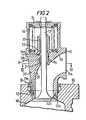
- Figure 2 is a longitudinal cross-sectional view, similar to Figure 1, showing the preferred construction according to the present invention, and
- Figure 3 is a transverse cross-sectional view taken along line III-III of Figure 2.
- Referring now to Figures 2 and 3 of the drawings, the
exhaust valve casing 11 is provided at its inner end with a wall part defining avalve seat 12 and avalve 13 is supported in the casing by the intermediary of avalve spring 14 and aspring cap 15. The exhaust valve thus provides an exhaust gas passage and valve assembly which is independent of thecylinder head 16. The stem of thevalve 13 is slidably mounted in avalve guide bush 17. Thevalve casing 11 is fastened jointly with thevalve seat 12 to thecylinder head 16 in a pressure-tight manner by means of bolts 19 (see Figure 3). In this figure,reference numeral 20 designates ribs provided for enabling transmission of a uniform stress in a circumferential direction through acontact surface 12a (see Figure 2) between the valve seat and cylinder head. - An
annular cooling chamber 11c is formed along an outer periphery of thevalve guide bush 17, and coolant is introduced thereto through acoolant inlet duct 11b and discharged through acoolant outlet duct 11d. To prevent coolant from leaking out of thecooling chamber 11c,seals 21 are provided in thevalve guide bush 17. - A second
annular cooling chamber 12b, is formed within the wall part defining thevalve seat 12, and coolant is introduced to this chamber through acoolant inlet duct 11 and discharged through a coolant outlet duct (not shown). - In this preferred construction of exhaust valve, in order to reduce thermal loss from the exhaust gas caused by heat transfer to the coolant, cooling of a
peripheral wall 11f around theexhaust passage 11 a by means of coolant, is practiced in the known construction discussed above, is abolished. Furthermore the cooling arrangement is constructed in such a manner that only the two locations described above are cooled by the coolant. - More particularly, through the temperature of the valve casing is raised as a whole due to the abolition of cooling of the
peripheral wall 11f around theexhaust passage 11a, in order to prevent degradation of the lubricating capability of thevalve guide bush 17 due to increased temperature in the material of the valve casing, the outer periphery of thevalve guide bush 17 is positively cooled by means of the coolant. In addition, in a similar manner to the known construction, thevalve seat 12 is positively cooled by coolant. Furthermore, theperipheral wall 11f around theexhaust passage 11 of theexhaust valve casing 11 is lagged externally by a heat-insulating materia) 11g (see Figure 3) such as, for example, asbestos. - In the cooling arrangement described coolant is introduced through the
coolant inlet duct 11 for valve seat cooling as shown by arrow B, and flows into thecooling chamber 12b, and thereafter, around the cooling chamber, to be discharged externally through the coolant outlet duct. Coolant is also introduced through thecoolant inlet duct 11 b for thevalve guide bush 17 as shown by an arrow A, to flow into thecooling chamber 11c along the outer periphery of thebush 17 and to be discharged externally through thecoolant outlet duct 11d.
Claims (3)
Priority Applications (2)
| Application Number | Priority Date | Filing Date | Title |
|---|---|---|---|
| EP19810304727EP0076348B1 (en) | 1981-10-12 | 1981-10-12 | Exhaust valve casing |
| DE8181304727TDE3171601D1 (en) | 1981-10-12 | 1981-10-12 | Exhaust valve casing |
Applications Claiming Priority (1)
| Application Number | Priority Date | Filing Date | Title |
|---|---|---|---|
| EP19810304727EP0076348B1 (en) | 1981-10-12 | 1981-10-12 | Exhaust valve casing |
Publications (2)
| Publication Number | Publication Date |
|---|---|
| EP0076348A1 EP0076348A1 (en) | 1983-04-13 |
| EP0076348B1true EP0076348B1 (en) | 1985-07-31 |
Family
ID=8188433
Family Applications (1)
| Application Number | Title | Priority Date | Filing Date |
|---|---|---|---|
| EP19810304727ExpiredEP0076348B1 (en) | 1981-10-12 | 1981-10-12 | Exhaust valve casing |
Country Status (2)
| Country | Link |
|---|---|
| EP (1) | EP0076348B1 (en) |
| DE (1) | DE3171601D1 (en) |
Cited By (1)
| Publication number | Priority date | Publication date | Assignee | Title |
|---|---|---|---|---|
| DE10159100B4 (en)* | 2001-12-01 | 2004-09-16 | Man B&W Diesel A/S | reciprocating engine |
Families Citing this family (3)
| Publication number | Priority date | Publication date | Assignee | Title |
|---|---|---|---|---|
| CN1074516C (en)* | 1999-02-13 | 2001-11-07 | 董永钏 | Ball valve |
| DE19943264C2 (en)* | 1999-09-10 | 2002-07-25 | Man B & W Diesel As Kopenhagen | Reciprocating engine, especially a large two-stroke diesel engine |
| CN104847521A (en)* | 2015-05-13 | 2015-08-19 | 柳州金盾机械有限公司 | Loader cylinder cover structure |
Family Cites Families (9)
| Publication number | Priority date | Publication date | Assignee | Title |
|---|---|---|---|---|
| GB1068041A (en)* | 1963-01-05 | 1967-05-10 | Mirrlees Nat Ltd | Improvements in or relating to caged valves for internal combustion engines |
| GB1100403A (en)* | 1965-03-17 | 1968-01-24 | Mirrlees Nat Ltd | Improvements in or relating to caged poppet valves for internal combustion engines |
| FR2259232B1 (en)* | 1974-01-29 | 1976-06-25 | Semt | |
| DD110682A1 (en)* | 1974-02-14 | 1975-01-05 | ||
| DE2410893C2 (en)* | 1974-03-07 | 1982-09-16 | M.A.N. Maschinenfabrik Augsburg-Nürnberg AG, 8900 Augsburg | Valve cage for internal combustion engines |
| DE2441689A1 (en)* | 1974-08-30 | 1976-03-11 | Maschf Augsburg Nuernberg Ag | DEVICE FOR COOLING VALVES, IN PARTICULAR EXHAUST VALVES FOR COMBUSTION MACHINERY |
| FR2308787A1 (en)* | 1975-04-22 | 1976-11-19 | Honda Motor Co Ltd | INTERNAL COMBUSTION ENGINE IMPROVEMENTS |
| CH614014A5 (en)* | 1977-01-28 | 1979-10-31 | Sulzer Ag | |
| DE2737689A1 (en)* | 1977-08-20 | 1979-02-22 | Maschf Augsburg Nuernberg Ag | VALVE ARRANGEMENT |
- 1981
- 1981-10-12DEDE8181304727Tpatent/DE3171601D1/ennot_activeExpired
- 1981-10-12EPEP19810304727patent/EP0076348B1/ennot_activeExpired
Cited By (1)
| Publication number | Priority date | Publication date | Assignee | Title |
|---|---|---|---|---|
| DE10159100B4 (en)* | 2001-12-01 | 2004-09-16 | Man B&W Diesel A/S | reciprocating engine |
Also Published As
| Publication number | Publication date |
|---|---|
| EP0076348A1 (en) | 1983-04-13 |
| DE3171601D1 (en) | 1985-09-05 |
Similar Documents
| Publication | Publication Date | Title |
|---|---|---|
| US3673798A (en) | Turbocharged internal combustion engine | |
| US5052349A (en) | Rotary valve for internal combustion engine | |
| WO2001065092A1 (en) | Four stroke engine with cooling system | |
| FI66057C (en) | VAETSKEKYLT FOER EN FYRTAKTS-DIESELMOTOR AVSETT CYLINDERLOCK | |
| JP2575807B2 (en) | Cylinder head cooling structure for 4-cycle engine | |
| SE9300192D0 (en) | CYLINDER LINER WITH COOLANT SLEEVE | |
| US4034723A (en) | Insulated, high efficiency, low heat rejection, engine cylinder head | |
| JP3012796U (en) | Exhaust liner and seal assembly | |
| JPS59101565A (en) | Cylinder liner | |
| US4129101A (en) | Internal combustion engine | |
| US4941436A (en) | Cooling system for I.C.E. valve seat inserts | |
| EP0076348B1 (en) | Exhaust valve casing | |
| US4127096A (en) | Internal combustion engine | |
| US4864985A (en) | Rotary valve | |
| KR100319179B1 (en) | Internal combustion engine block with cylinder liner decentralized flow cooling system and its cooling method | |
| US3400695A (en) | Internal combustion engine and cylinder block | |
| NO149184B (en) | DEVICE FOR REFRIGERATING CYLINDER COVER FOR FIRTACT DIESEL ENGINES | |
| CA1055346A (en) | Insulated, high efficiency, low heat rejection, engine cylinder head | |
| GB2099075A (en) | A cylinder block for an internal combustion engine | |
| JPH0613861B2 (en) | Two-cycle engine piston | |
| US4864981A (en) | Overhead valve type engine | |
| US3020707A (en) | Engine exhaust manifold construction | |
| US5809960A (en) | Intake pipe in an internal combustion engine with carburetor | |
| JPS6124652Y2 (en) | ||
| US4403577A (en) | Free piston internal combustion engines |
Legal Events
| Date | Code | Title | Description |
|---|---|---|---|
| PUAI | Public reference made under article 153(3) epc to a published international application that has entered the european phase | Free format text:ORIGINAL CODE: 0009012 | |
| AK | Designated contracting states | Designated state(s):CH DE FR GB LI NL SE | |
| 17P | Request for examination filed | Effective date:19831003 | |
| GRAA | (expected) grant | Free format text:ORIGINAL CODE: 0009210 | |
| AK | Designated contracting states | Designated state(s):CH DE FR GB LI NL SE | |
| REF | Corresponds to: | Ref document number:3171601 Country of ref document:DE Date of ref document:19850905 | |
| ET | Fr: translation filed | ||
| PLBE | No opposition filed within time limit | Free format text:ORIGINAL CODE: 0009261 | |
| STAA | Information on the status of an ep patent application or granted ep patent | Free format text:STATUS: NO OPPOSITION FILED WITHIN TIME LIMIT | |
| 26N | No opposition filed | ||
| PGFP | Annual fee paid to national office [announced via postgrant information from national office to epo] | Ref country code:NL Payment date:19871031 Year of fee payment:7 | |
| REG | Reference to a national code | Ref country code:GB Ref legal event code:746 | |
| REG | Reference to a national code | Ref country code:FR Ref legal event code:DL | |
| PG25 | Lapsed in a contracting state [announced via postgrant information from national office to epo] | Ref country code:GB Effective date:19891012 | |
| PG25 | Lapsed in a contracting state [announced via postgrant information from national office to epo] | Ref country code:SE Effective date:19891013 | |
| PG25 | Lapsed in a contracting state [announced via postgrant information from national office to epo] | Ref country code:NL Effective date:19900501 | |
| GBPC | Gb: european patent ceased through non-payment of renewal fee | ||
| NLV4 | Nl: lapsed or anulled due to non-payment of the annual fee | ||
| EUG | Se: european patent has lapsed | Ref document number:81304727.1 Effective date:19900705 | |
| PGFP | Annual fee paid to national office [announced via postgrant information from national office to epo] | Ref country code:FR Payment date:19951010 Year of fee payment:15 | |
| PG25 | Lapsed in a contracting state [announced via postgrant information from national office to epo] | Ref country code:FR Effective date:19970630 | |
| REG | Reference to a national code | Ref country code:FR Ref legal event code:ST | |
| PGFP | Annual fee paid to national office [announced via postgrant information from national office to epo] | Ref country code:DE Payment date:19981016 Year of fee payment:18 | |
| PGFP | Annual fee paid to national office [announced via postgrant information from national office to epo] | Ref country code:CH Payment date:19981022 Year of fee payment:18 | |
| PG25 | Lapsed in a contracting state [announced via postgrant information from national office to epo] | Ref country code:LI Free format text:LAPSE BECAUSE OF NON-PAYMENT OF DUE FEES Effective date:19991031 Ref country code:CH Free format text:LAPSE BECAUSE OF NON-PAYMENT OF DUE FEES Effective date:19991031 | |
| REG | Reference to a national code | Ref country code:CH Ref legal event code:PL | |
| PG25 | Lapsed in a contracting state [announced via postgrant information from national office to epo] | Ref country code:DE Free format text:LAPSE BECAUSE OF NON-PAYMENT OF DUE FEES Effective date:20000801 |