EP0073123B1 - Blood pressure measurement - Google Patents
Blood pressure measurementDownload PDFInfo
- Publication number
- EP0073123B1 EP0073123B1EP82304266AEP82304266AEP0073123B1EP 0073123 B1EP0073123 B1EP 0073123B1EP 82304266 AEP82304266 AEP 82304266AEP 82304266 AEP82304266 AEP 82304266AEP 0073123 B1EP0073123 B1EP 0073123B1
- Authority
- EP
- European Patent Office
- Prior art keywords
- zone
- pressure
- occluding
- detector
- blood
- Prior art date
- Legal status (The legal status is an assumption and is not a legal conclusion. Google has not performed a legal analysis and makes no representation as to the accuracy of the status listed.)
- Expired
Links
- 238000009530blood pressure measurementMethods0.000titleclaimsdescription3
- 239000008280bloodSubstances0.000claimsdescription21
- 210000004369bloodAnatomy0.000claimsdescription21
- 230000003205diastolic effectEffects0.000claimsdescription10
- 230000035487diastolic blood pressureEffects0.000claimsdescription9
- 230000035488systolic blood pressureEffects0.000claimsdescription7
- 230000000750progressive effectEffects0.000claimsdescription3
- 230000005855radiationEffects0.000claims4
- 239000002775capsuleSubstances0.000description10
- 210000001367arteryAnatomy0.000description7
- 230000002792vascularEffects0.000description6
- 239000012530fluidSubstances0.000description5
- 230000036772blood pressureEffects0.000description4
- 210000000624ear auricleAnatomy0.000description4
- 230000004872arterial blood pressureEffects0.000description3
- 230000005540biological transmissionEffects0.000description3
- 238000011161developmentMethods0.000description3
- 230000006872improvementEffects0.000description3
- 238000005259measurementMethods0.000description3
- 230000003287optical effectEffects0.000description3
- 238000010521absorption reactionMethods0.000description2
- 230000017531blood circulationEffects0.000description2
- 210000004204blood vesselAnatomy0.000description2
- 230000008859changeEffects0.000description2
- 238000001514detection methodMethods0.000description2
- 238000000034methodMethods0.000description2
- 230000004044responseEffects0.000description2
- 210000001519tissueAnatomy0.000description2
- 230000007704transitionEffects0.000description2
- 230000009471actionEffects0.000description1
- 238000013459approachMethods0.000description1
- 210000002565arterioleAnatomy0.000description1
- 238000002555auscultationMethods0.000description1
- 210000000988bone and boneAnatomy0.000description1
- 230000000747cardiac effectEffects0.000description1
- 238000007796conventional methodMethods0.000description1
- 230000003247decreasing effectEffects0.000description1
- 201000010099diseaseDiseases0.000description1
- 208000037265diseases, disorders, signs and symptomsDiseases0.000description1
- 230000000694effectsEffects0.000description1
- 239000013536elastomeric materialSubstances0.000description1
- 230000002706hydrostatic effectEffects0.000description1
- 239000007788liquidSubstances0.000description1
- 230000000541pulsatile effectEffects0.000description1
- 230000009467reductionEffects0.000description1
- 230000003252repetitive effectEffects0.000description1
- 229910052710siliconInorganic materials0.000description1
- 239000010703siliconSubstances0.000description1
- XLYOFNOQVPJJNP-UHFFFAOYSA-NwaterSubstancesOXLYOFNOQVPJJNP-UHFFFAOYSA-N0.000description1
Images


Classifications
- A—HUMAN NECESSITIES
- A61—MEDICAL OR VETERINARY SCIENCE; HYGIENE
- A61B—DIAGNOSIS; SURGERY; IDENTIFICATION
- A61B5/00—Measuring for diagnostic purposes; Identification of persons
- A61B5/02—Detecting, measuring or recording for evaluating the cardiovascular system, e.g. pulse, heart rate, blood pressure or blood flow
- A61B5/021—Measuring pressure in heart or blood vessels
- A61B5/022—Measuring pressure in heart or blood vessels by applying pressure to close blood vessels, e.g. against the skin; Ophthalmodynamometers
- A61B5/0225—Measuring pressure in heart or blood vessels by applying pressure to close blood vessels, e.g. against the skin; Ophthalmodynamometers the pressure being controlled by electric signals, e.g. derived from Korotkoff sounds
- A61B5/02255—Measuring pressure in heart or blood vessels by applying pressure to close blood vessels, e.g. against the skin; Ophthalmodynamometers the pressure being controlled by electric signals, e.g. derived from Korotkoff sounds the pressure being controlled by plethysmographic signals, e.g. derived from optical sensors
- A—HUMAN NECESSITIES
- A61—MEDICAL OR VETERINARY SCIENCE; HYGIENE
- A61B—DIAGNOSIS; SURGERY; IDENTIFICATION
- A61B5/00—Measuring for diagnostic purposes; Identification of persons
- A61B5/02—Detecting, measuring or recording for evaluating the cardiovascular system, e.g. pulse, heart rate, blood pressure or blood flow
- A61B5/024—Measuring pulse rate or heart rate
- A61B5/0245—Measuring pulse rate or heart rate by using sensing means generating electric signals, i.e. ECG signals
- A61B5/025—Measuring pulse rate or heart rate by using sensing means generating electric signals, i.e. ECG signals within occluders, e.g. responsive to Korotkoff sounds
Definitions
- the normal method of measuring blood pressure by non-invasive meansentails the use of an inflatable cuff for location around the upper arm and some means for detecting the flow of blood at a location distal to the cuff.
- the cuffis inflated to a pressure at which the embraced tissue is compressed and all blood vessels therein, including the arteries, are occluded.
- the pressure in the cuffis then gradually reduced and the arteries start to open transiently to allow blood flow as soon as the cuff pressure falls below the peak systolic level.
- the arteriesremain patent for an increasing proportion of the cardiac cycle as the cuff pressure is further reduced, until the pressure falls below the diastolic level. Following this last event, the arteries remain patent throughout the cycle and the flow of blood is determined only by the normal pressure cycle.
- the distally located detecting meanswhich is commonly a stethoscope or an electronic equivalent, readily enables the first onset of blood flow to be detected at systolic pressure.
- the change in flowis much more subtle and difficult to detect because the flow approaches its unobstructed level at this time in an asymptotic manner. In the result, measurements of diastolic pressure are commonly inaccurate and of poor reproducibility.
- a cuff or equivalent devicecan be employed in association, at the same site, with some means for detecting variations in the blood volume in the body zone embraced by the cuff as that zone is variably occluded.
- One such proposal(Wood et al., Staff Meetings of the Mayo Clinic, pp. 398-405, July 5, 1950) suggests that systolic and diastolic pressure measurements are given by the cuff pressure when the detector respectively shows a first output and then a maximum output as the cuff pressure is continuously decreased from a level above systolic to one below diastolic.
- the results given with this proposalare such as to suggest no marked improvement over conventional methods of measuring blood pressure by non-invasive means. Again, the measurement of diastolic pressure is of poor accuracy.
- An object of the present inventionis to improve the above situation and this improvement rests on the finding that the blood volume in a body zone changes in two distinct phases when subjected to a progressive variation of externally applied pressure to or from a level causing occlusion of the zone, and that these two phases are respectively associated with transition of the external pressure through the systolic and diastolic levels.
- Figure 1is in three parts of which the first, denoted (a), shows a cyclically repetitive waveform having a triangular wave-shape to represent in an idealised manner the pulsatile arterial blood pressure in a body zone to which the invention is to be applied. Across this waveform is superimposed a linearly declining characteristic to represent external pressure applied to the body zone to occlude variably the same by uniform reduction from a pressure above systolic to one below diastolic.
- the second part of Figure 1, denoted (b),shows the resultant variation in blood volume which might be expected, from an idealised point of view, to be detected by the invention in the relevant zone.
- the reason for this shiftis that the vessels of the vascular system are not responsive to the various pressure changes in an ideal manner. More particularly, it is found that the vessels are _not absolutely occluded by an external pressure equal to systolic, but rather a higher pressure is required. Correspondingly, therefore, the first detector output occurs in Figure 1(c) when the external pressure falls to this higher value, or some other value close thereto if there is any hysteresis in the action of the vessel.
- the present inventionprovides apparatus for carrying out the procedure just described and accordingly comprises means for variably occluding a body zone by progressive application of external pressure between levels respectively above systolic and below diastolic, means for detecting variations in the blood volume in said zone during variable occlusion thereof, and means responsive to said occluding and detecting means to indicate the relevant values of said external pressure corresponding to the systolic and diastolic pressures.
- This apparatusis open to variation in respect of the occluding and detecting means, but the former is at present preferably adapted for location around a relatively thin body zone, such as an ear lobe or finger, which allows detection on the basis of variation, with blood content, of light transmission through the zone.
- a relatively thin body zonesuch as an ear lobe or finger
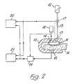
- Figure 2diagrammatically illustrates one form of such preferred apparatus adapted for application about an ear lobe.
- This apparatuscomprises a pincer-like structure formed by a generally U-shaped rigid body 10 having an inflatable capsule 11 mounted on the inner face of the free end portion of one U-arm of the body 10.
- the capsuleis made of an elastomeric material which is substantially uniformly light transmissive, and the capsule is inflatable by any suitably controllable source 12 of pressurised fluid communicated with the interior of the capsule by a tube 13 passing through the relevant arm portion of the body 10.
- the body 10is located about an ear lobe 16, and the capsule is first pressurised to occlude totally all blood vessels between the capsule and opposed arm, this being denoted by a constant output from the detector in response to light transmitted thereto by the source through the lobe. Thereafter the pressure in the capsule is reduced and an indication given of its values corresponding to systolic and diastolic pressures.
- One such locationis within the capsule or other pressure applying means, where the transducer will detect the pressure applied without error due to losses along the pressure fluid supply tube. This is relevant particularly when the pressure fluid is air or other gas.
- the hydrostatic pressure variations in the vascular system relative to the heart as blood pressure sourceare preferably off-set by locating the transducer at the level of the heart. Location of the transducer within the capsule or other pressure applying means is accordingly best suited to apparatus applicable to a finger or other body zone readily movable to maintain this level.
- the pressure fluidis preferably water or other liquid so that pressure variations within the apparatus are minimised.
- Figure 2shows in broken line a pressure transducer 17 in each of these alternative locations.
- the light sourceis preferably energised from a pulsed supply 18 to minimise power consumption, and the detector output is gated at 19 by the supply 18 so that response to external light sources, whether generally constant or flickering, is minimal.
- the light source 14suitably produces green light when applied to a body zone such as the ear lobe which is thin and without the presence of bone.
- the coefficient of absorption of green light in bloodis high and transmission variations with blood content will be maximised in these circumstances.
- infrared lightwill normally be preferred because of its enhanced transmission through tissue.
- thisis suitably an appropriately designed microprocessor 20 responsive to the detector 16 and pressure transducer 17 to determine the relevant values by reference to the detector output variations as described above.
- the indicator outputcan involve digital display and/or printed record.
- blood volume detection by optical meansis applicable in association with a conventional form of cuff for the finger or arm, the cuff preferably having the optical means moulded into its inner wall flush with the surface thereof.
- Figure 3shows a typical pen recorder output obtained in such development, it being noted that blood volume level is shown by a downward excursion from the zero datum in this case.
- the possibility for variationalso extends to the blood volume detecting means and alternatives to optical forms include a strain gauge to respond to variation of the body zone geometry with blood volume, proton magnetic resonance to respond to variation of fluid content, and microwave absorption, for example.
Landscapes
- Health & Medical Sciences (AREA)
- Life Sciences & Earth Sciences (AREA)
- Cardiology (AREA)
- Vascular Medicine (AREA)
- Engineering & Computer Science (AREA)
- Pathology (AREA)
- Public Health (AREA)
- Physics & Mathematics (AREA)
- Veterinary Medicine (AREA)
- Biophysics (AREA)
- Physiology (AREA)
- Biomedical Technology (AREA)
- Heart & Thoracic Surgery (AREA)
- Medical Informatics (AREA)
- Molecular Biology (AREA)
- Surgery (AREA)
- Animal Behavior & Ethology (AREA)
- General Health & Medical Sciences (AREA)
- Dentistry (AREA)
- Signal Processing (AREA)
- Ophthalmology & Optometry (AREA)
- Measuring Pulse, Heart Rate, Blood Pressure Or Blood Flow (AREA)
Description
- The normal method of measuring blood pressure by non-invasive means entails the use of an inflatable cuff for location around the upper arm and some means for detecting the flow of blood at a location distal to the cuff. The cuff is inflated to a pressure at which the embraced tissue is compressed and all blood vessels therein, including the arteries, are occluded. The pressure in the cuff is then gradually reduced and the arteries start to open transiently to allow blood flow as soon as the cuff pressure falls below the peak systolic level. Thereafter, the arteries remain patent for an increasing proportion of the cardiac cycle as the cuff pressure is further reduced, until the pressure falls below the diastolic level. Following this last event, the arteries remain patent throughout the cycle and the flow of blood is determined only by the normal pressure cycle.
- The distally located detecting means, which is commonly a stethoscope or an electronic equivalent, readily enables the first onset of blood flow to be detected at systolic pressure. However, at diastolic pressure the change in flow is much more subtle and difficult to detect because the flow approaches its unobstructed level at this time in an asymptotic manner. In the result, measurements of diastolic pressure are commonly inaccurate and of poor reproducibility.
- In accordance with other proposals for measuring blood pressure, a cuff or equivalent device can be employed in association, at the same site, with some means for detecting variations in the blood volume in the body zone embraced by the cuff as that zone is variably occluded. One such proposal (Wood et al., Staff Meetings of the Mayo Clinic, pp. 398-405, July 5, 1950) suggests that systolic and diastolic pressure measurements are given by the cuff pressure when the detector respectively shows a first output and then a maximum output as the cuff pressure is continuously decreased from a level above systolic to one below diastolic. However, the results given with this proposal are such as to suggest no marked improvement over conventional methods of measuring blood pressure by non-invasive means. Again, the measurement of diastolic pressure is of poor accuracy.
- An object of the present invention is to improve the above situation and this improvement rests on the finding that the blood volume in a body zone changes in two distinct phases when subjected to a progressive variation of externally applied pressure to or from a level causing occlusion of the zone, and that these two phases are respectively associated with transition of the external pressure through the systolic and diastolic levels.
- A fuller understanding of this finding, and of the invention and its operation will be gained by consideration of the accompanying drawings, in which:-
- Figure 1 graphically illustrates the operational basis for the invention;
- Figure 2 diagrammatically illustrates one presently preferred form of the invention;
- Figure 3 graphically illustrates an output obtained with an embodiment of the invention; and
- Figure 4 is a histogram indicating the relative accuracy of a series of results obtained with the last-mentioned embodiment.
- Figure 1 is in three parts of which the first, denoted (a), shows a cyclically repetitive waveform having a triangular wave-shape to represent in an idealised manner the pulsatile arterial blood pressure in a body zone to which the invention is to be applied. Across this waveform is superimposed a linearly declining characteristic to represent external pressure applied to the body zone to occlude variably the same by uniform reduction from a pressure above systolic to one below diastolic.
- The second part of Figure 1, denoted (b), shows the resultant variation in blood volume which might be expected, from an idealised point of view, to be detected by the invention in the relevant zone.
- Initially, when the external pressure is above systolic, all of the blood is squeezed out of the zone and there is accordingly no change in output from the detector.
- As the external pressure falls to and below systolic, blood enters the arteries in the zone during that part of the pulse cycle during which the arterial pressure is higher than the former pressure, and is squeezed out again during the remainder of the cycle. This is indicated by the first occurrence of a detector output coincident with equality between the external and systolic pressures, which occurrence is denoted by a broken vertical line S through Figure 1, the detector output thereafter progressively increasing during this first phase of blood volume variation.
- The continuing fall of the external pressure below systolic and towards diastolic can next produee a situation when the external pressure is lower than the arterial pressure throughout the cycle and at no time is all of the blood squeezed out of the arteries. Under these conditions the detector output is uniform.
- Finally, yet further decrease of the external pressure towards and beyond diastolic allows blood to enter and to remain in other parts of the vascular system in the zone; first the arterioles, then the capillaries, and lastly the venous system. During this second phase of blood volume variation the detector output increases again in conformity with the changes in the zone. The diastolic end point is clearly and unambiguously defined by the point in this last phase when the vascular system is no longer bloodless at any time in the pulse cycle. This point is indicated by commencement of the further increase in detector output and is denoted by the broken vertical line D through Figure 1 when the external and diastolic pressures are equal.
- In reality, development of the present invention shows a result as in the third part of Figure 1, denoted (c), which is closely similar to that of Figure 1 (b) but is shifted in its relationship with Figure 1(a).
- The reason for this shift is that the vessels of the vascular system are not responsive to the various pressure changes in an ideal manner. More particularly, it is found that the vessels are _not absolutely occluded by an external pressure equal to systolic, but rather a higher pressure is required. Correspondingly, therefore, the first detector output occurs in Figure 1(c) when the external pressure falls to this higher value, or some other value close thereto if there is any hysteresis in the action of the vessel.
- A similar effect is found in connection with the transition from flow in the arteries to flow elsewhere in the vascular system, and the final phase of detector output variation occurs when the external pressure falls to a value in excess of diastolic.
- These differences between idealised and real life situations are not found to be related in a precisely predictable manner because the general condition or so-called tone of the vascular vessels varies from one individual to another. Factors in such variation are age and disease.
- However, it has been found that a close indication of the actual systolic and diastolic pressures is given by the value of the external pressures respectively when the peaks and valleys of the first and second phases of varying detector output are each about half-way between zero and the uniform level of the intervening phase or, more generally, insofar as there may not be a uniform level, about half-way between zero and the peak following the last valley which does not depart significantly from zero.
- The present invention provides apparatus for carrying out the procedure just described and accordingly comprises means for variably occluding a body zone by progressive application of external pressure between levels respectively above systolic and below diastolic, means for detecting variations in the blood volume in said zone during variable occlusion thereof, and means responsive to said occluding and detecting means to indicate the relevant values of said external pressure corresponding to the systolic and diastolic pressures.
- This apparatus is open to variation in respect of the occluding and detecting means,, but the former is at present preferably adapted for location around a relatively thin body zone, such as an ear lobe or finger, which allows detection on the basis of variation, with blood content, of light transmission through the zone.
- Figure 2 diagrammatically illustrates one form of such preferred apparatus adapted for application about an ear lobe.
- This apparatus comprises a pincer-like structure formed by a generally U-shaped
rigid body 10 having an inflatable capsule 11 mounted on the inner face of the free end portion of one U-arm of thebody 10. The capsule is made of an elastomeric material which is substantially uniformly light transmissive, and the capsule is inflatable by any suitablycontrollable source 12 of pressurised fluid communicated with the interior of the capsule by atube 13 passing through the relevant arm portion of thebody 10. - A
light source 14, suitably of light emitting diode form, is mounted in the arm within the space defined by the capsule to face towards aphotoelectric detector 15, suitably in the form of a silicon photovoltaic cell, mounted in the opposite arm of thebody 10. - Use of this apparatus is largely self-evident from the foregoing description. The
body 10 is located about anear lobe 16, and the capsule is first pressurised to occlude totally all blood vessels between the capsule and opposed arm, this being denoted by a constant output from the detector in response to light transmitted thereto by the source through the lobe. Thereafter the pressure in the capsule is reduced and an indication given of its values corresponding to systolic and diastolic pressures. - Clearly the apparatus will require a pressure transducer and various suitable forms are readily available. Generally speaking, two locations are preferred for such a transducer, the choice of location depending on the form of apparatus in question.
- One such location is within the capsule or other pressure applying means, where the transducer will detect the pressure applied without error due to losses along the pressure fluid supply tube. This is relevant particularly when the pressure fluid is air or other gas. However, another factor is that the hydrostatic pressure variations in the vascular system relative to the heart as blood pressure source are preferably off-set by locating the transducer at the level of the heart. Location of the transducer within the capsule or other pressure applying means is accordingly best suited to apparatus applicable to a finger or other body zone readily movable to maintain this level.
- The other location is apparent from these last comments, namely, within a separate unit connected by a flexible tube with the remainder of the apparatus, such unit being locatable over the heart. In this case, the pressure fluid is preferably water or other liquid so that pressure variations within the apparatus are minimised.
- Figure 2 shows in broken line a
pressure transducer 17 in each of these alternative locations. - In operation of the apparatus the light source is preferably energised from a
pulsed supply 18 to minimise power consumption, and the detector output is gated at 19 by thesupply 18 so that response to external light sources, whether generally constant or flickering, is minimal. - The
light source 14 suitably produces green light when applied to a body zone such as the ear lobe which is thin and without the presence of bone. The coefficient of absorption of green light in blood is high and transmission variations with blood content will be maximised in these circumstances. For other body zones, infrared light will normally be preferred because of its enhanced transmission through tissue. - Regarding the output indicator: this is suitably an appropriately designed
microprocessor 20 responsive to thedetector 16 andpressure transducer 17 to determine the relevant values by reference to the detector output variations as described above. The indicator output can involve digital display and/or printed record. - It will also often be desirable to have a printed record of the overall detector output and this can be provided by a
pen recorder 21 or other suitable means. - While the invention has been described above as a specific illustrated embodiment, other comment has made it clear that the invention is open to variation. For example, blood volume detection by optical means is applicable in association with a conventional form of cuff for the finger or arm, the cuff preferably having the optical means moulded into its inner wall flush with the surface thereof. Indeed the latest development of the invention has involved a finger cuff form and Figure 3 shows a typical pen recorder output obtained in such development, it being noted that blood volume level is shown by a downward excursion from the zero datum in this case.
- The overall improvement of the invention relative to the prior art is shown by the histogram of Figure 4 in which the hatched area shows the errors obtained by conventional auscultation compared to intravascular measurement based on data from Bruneret et al. (
Medical Instrumentation 15; 1, 2 and 3; 1981) and the non-hatched area shows the clearly lesser errors obtained with a finger cuff according to the invention. - The possibility for variation also extends to the blood volume detecting means and alternatives to optical forms include a strain gauge to respond to variation of the body zone geometry with blood volume, proton magnetic resonance to respond to variation of fluid content, and microwave absorption, for example.
Claims (10)
1. Blood pressure measurement apparatus comprising means (1D-13).for variably occluding a body zone (16) by progressive application of external pressure between levels respectively above systolic and below diastolic, and means (14, 15) for detecting variations in the blood volume in said zone during variable occlusion thereof, said variations comprising successively alternating peaks and valleys, characterised by means (20) responsive to said occluding and detecting means to indicate as systolic and diastolic pressures the values of said external pressure respectively when the peaks and valleys determined by said detector are each about half-way between zero and the level of the first peak following the last valley which does not depart significantly from zero.
2. Apparatus according to Claim 1 characterised in that said detecting means comprises a radiation generator (14, 18) and detector (15) mounted in said occluding means for location in opposition about said zone.
3. Apparatus according to Claim 2 characterised in that said radiation is light.
4. Apparatus according to Claim 3 characterised in that said radiation is infra-red.
5. Apparatus according to Claim 3 or 4 characterised in that said generator provides a pulsed output and the output of said detector is applied to said indicating means in synchronism (19) with said pulsed output.
6. Apparatus according to Claim 1 characterised in that said detecting means comprises a strain gauge responsive to variations in the geometry of said body zone with blood volume therein.
7. Apparatus according to Claim 1 characterised in that said detecting means responds to variation in proton magnetic resonance within said zone.
8. Apparatus according to Claim 2 characterised in that said radiation is of microwave form.
9. Apparatus according to any preceding claim characterised in that said occluding means comprises a gas-inflatable device (11) locatable around said body zone, and a pressure transducer (17) mounted in said device for location closely adjacent said zone.
10. Apparatus according to any one of Claims 1 to 8 characterised in that said occluding means comprises a liquid-inflatable device (11) locatable around said body zone, and a pressure transducer (17) coupled with said device by way of a flexible tube (13) for location remotely from said body zone.
Applications Claiming Priority (2)
| Application Number | Priority Date | Filing Date | Title |
|---|---|---|---|
| GB8125592 | 1981-08-21 | ||
| GB8125592 | 1981-08-21 |
Publications (3)
| Publication Number | Publication Date |
|---|---|
| EP0073123A2 EP0073123A2 (en) | 1983-03-02 |
| EP0073123A3 EP0073123A3 (en) | 1984-07-18 |
| EP0073123B1true EP0073123B1 (en) | 1987-04-01 |
Family
ID=10524099
Family Applications (1)
| Application Number | Title | Priority Date | Filing Date |
|---|---|---|---|
| EP82304266AExpiredEP0073123B1 (en) | 1981-08-21 | 1982-08-12 | Blood pressure measurement |
Country Status (5)
| Country | Link |
|---|---|
| US (1) | US4730621A (en) |
| EP (1) | EP0073123B1 (en) |
| JP (1) | JPS5841529A (en) |
| DE (1) | DE3275900D1 (en) |
| GB (1) | GB2104223B (en) |
Families Citing this family (32)
| Publication number | Priority date | Publication date | Assignee | Title |
|---|---|---|---|---|
| JPH0626540B2 (en)* | 1985-04-12 | 1994-04-13 | オムロン株式会社 | Pulse wave detector |
| DE3829456A1 (en)* | 1988-08-31 | 1990-03-01 | Nicolay Gmbh | METHOD AND DEVICE FOR NON-INVASIVELY EXAMINING THE BLOOD CIRCUIT OF A LIVING ORGANISM |
| JPH02126830A (en)* | 1988-11-07 | 1990-05-15 | Nippon Koden Corp | Non-invasive automatic blood pressure measurement device |
| ATE125433T1 (en)* | 1989-07-13 | 1995-08-15 | Omron Tateisi Electronics Co | COVERING CUFF FOR BLOOD PRESSURE MONITOR. |
| JP2751441B2 (en)* | 1989-08-08 | 1998-05-18 | オムロン株式会社 | Cuff winding device for sphygmomanometer |
| US5103833A (en)* | 1989-12-20 | 1992-04-14 | Critikon, Inc. | Peripheral arterial monitoring instruments |
| US5054494A (en)* | 1989-12-26 | 1991-10-08 | U.S. Medical Corporation | Oscillometric blood pressure device |
| US5072736A (en)* | 1990-01-19 | 1991-12-17 | Nihon Kohden Corporation | Non-invasive automatic blood pressure measuring apparatus |
| EP0716829B1 (en)* | 1990-05-17 | 2002-07-24 | Mitsuei Tomita | Pulse wave detecting apparatus |
| US5651369A (en)* | 1992-01-13 | 1997-07-29 | Tomita; Mitsuei | Apparatus for detecting and displaying blood circulatory information |
| US5406954A (en)* | 1992-01-13 | 1995-04-18 | Tomita; Mitsuei | Apparatus for detecting and displaying blood circulatory information |
| US5282467A (en)* | 1992-08-13 | 1994-02-01 | Duke University | Non-invasive method for detecting deep venous thrombosis in the human body |
| US6172743B1 (en) | 1992-10-07 | 2001-01-09 | Chemtrix, Inc. | Technique for measuring a blood analyte by non-invasive spectrometry in living tissue |
| TW241196B (en)* | 1993-01-15 | 1995-02-21 | Du Pont | |
| US6882873B2 (en)* | 1996-01-17 | 2005-04-19 | Respironics, Inc. | Method and system for determining bilirubin concentration |
| DE60312200T2 (en)* | 2002-10-30 | 2007-11-08 | Dpcom As | METHOD FOR THE ANALYSIS OF SINGLE PULSE PRESSURE WAVES |
| US20070276264A1 (en)* | 2002-10-30 | 2007-11-29 | Eide Per K | Method for analysis of single pulse pressure waves |
| JP4179326B2 (en)* | 2003-10-09 | 2008-11-12 | 日本電信電話株式会社 | Biological information detection device and blood pressure monitor |
| KR20050117825A (en)* | 2004-06-11 | 2005-12-15 | 삼성전자주식회사 | Blood pressure measuring system and method of measuring blood pressure using the same |
| CN100496389C (en)* | 2004-10-06 | 2009-06-10 | 日本电信电话株式会社 | sphygmomanometer |
| WO2006038589A1 (en)* | 2004-10-06 | 2006-04-13 | Terumo Kabushiki Kaisha | Blood pressure measuring device and blood pressure measuring method |
| JP4460414B2 (en)* | 2004-10-06 | 2010-05-12 | 日本電信電話株式会社 | Sphygmomanometer |
| JP4185036B2 (en)* | 2004-10-06 | 2008-11-19 | 日本電信電話株式会社 | Sphygmomanometer |
| JP4559281B2 (en)* | 2005-04-08 | 2010-10-06 | テルモ株式会社 | Blood pressure measuring device |
| JP4468854B2 (en)* | 2005-04-08 | 2010-05-26 | テルモ株式会社 | Blood pressure measuring device |
| JP4559280B2 (en)* | 2005-04-08 | 2010-10-06 | テルモ株式会社 | Blood pressure measuring device |
| JP4559279B2 (en)* | 2005-04-08 | 2010-10-06 | テルモ株式会社 | Blood pressure measurement device, blood pressure measurement method, and control program |
| DE102006009942B4 (en)* | 2006-03-03 | 2012-02-09 | Infineon Technologies Austria Ag | Lateral semiconductor device with low on-resistance |
| JP4773177B2 (en)* | 2005-10-07 | 2011-09-14 | テルモ株式会社 | Blood pressure measurement device |
| CN101912259B (en)* | 2010-08-06 | 2012-10-10 | 深圳瑞光康泰科技有限公司 | Non-invasive blood pressure measuring device |
| JP6251997B2 (en)* | 2012-09-18 | 2017-12-27 | カシオ計算機株式会社 | Pulse data detection device, pulse data detection method, and pulse data detection program |
| DE102013017716A1 (en) | 2013-10-24 | 2015-04-30 | Nicolay Verwaltung Gmbh | Method and device for non-invasive blood pressure measurement |
Family Cites Families (16)
| Publication number | Priority date | Publication date | Assignee | Title |
|---|---|---|---|---|
| US3051165A (en)* | 1959-10-14 | 1962-08-28 | Honeywell Regulator Co | Apparatus for automatically measuring blood pressure and pulse rate |
| US3192921A (en)* | 1961-07-10 | 1965-07-06 | Honeywell Inc | Body function measuring apparatus |
| FR1334572A (en)* | 1961-07-10 | 1963-08-09 | Honeywell Regulator Co | Device for measuring blood pressure |
| US3229685A (en)* | 1963-04-19 | 1966-01-18 | Emerson Electric Co | Blood pressure measuring |
| US3482565A (en)* | 1964-03-24 | 1969-12-09 | Carter Wallace | Digital blood pressure measuring device |
| US3412729A (en)* | 1965-08-30 | 1968-11-26 | Nasa Usa | Method and apparatus for continuously monitoring blood oxygenation, blood pressure, pulse rate and the pressure pulse curve utilizing an ear oximeter as transducer |
| DE1541128B2 (en)* | 1966-07-29 | 1977-06-23 | Hellige GmbH, 7800 Freiburg Elf: Streu, Benno, 7800 Freiburg | BLOOD PRESSURE MONITOR WITH AUTOMATIC DETERMINATION OF DIASTOLIC AND SYSTOLIC BLOOD PRESSURE |
| US3993047A (en)* | 1974-07-10 | 1976-11-23 | Peek Sanford C | Instrumentation for monitoring blood circulation |
| US4009709A (en)* | 1975-05-15 | 1977-03-01 | American Optical Corporation | Apparatus and process for determining systolic pressure |
| US4105021A (en)* | 1976-08-13 | 1978-08-08 | Joseph H. Allen | Method and arrangement for measuring blood pressure |
| US4117835A (en)* | 1976-12-08 | 1978-10-03 | Weisman & Allen | Method and apparatus for blood pressure measurements |
| US4367751A (en)* | 1976-12-27 | 1983-01-11 | Warner-Lambert Company | Apparatus and process for producing artifact effect on sphygmometric information |
| US4271843A (en)* | 1978-10-10 | 1981-06-09 | Flynn George J | Method and apparatus for diastolic pressure measurement |
| DE3006477A1 (en)* | 1980-02-21 | 1981-09-03 | Philips Patentverwaltung Gmbh, 2000 Hamburg | CIRCUIT FOR MEASURING THE PULSE OF A PERSON WITH A CONTROLLABLE LIGHT SOURCE |
| NL8005145A (en)* | 1980-09-12 | 1982-04-01 | Tno | DEVICE FOR INDIRECT, NON-INVASIVE, CONTINUOUS MEASUREMENT OF BLOOD PRESSURE. |
| FR2498071A1 (en)* | 1981-01-16 | 1982-07-23 | Osoboe K Bjuro | Blood pressure measuring appts. - has differentiator supplying timing pulse shaper and integrator feeding discriminator |
- 1982
- 1982-08-12EPEP82304266Apatent/EP0073123B1/ennot_activeExpired
- 1982-08-12GBGB08223236Apatent/GB2104223B/ennot_activeExpired
- 1982-08-12DEDE8282304266Tpatent/DE3275900D1/ennot_activeExpired
- 1982-08-20JPJP57144590Apatent/JPS5841529A/enactiveGranted
- 1985
- 1985-12-03USUS06/804,242patent/US4730621A/ennot_activeExpired - Fee Related
Non-Patent Citations (1)
| Title |
|---|
| "Measurement of blood content and arterial pressure in the human ear", Wood et al., Staff Meetings of the Mayo Clinic, July 5, 1950, pages 398-405* |
Also Published As
| Publication number | Publication date |
|---|---|
| EP0073123A2 (en) | 1983-03-02 |
| GB2104223A (en) | 1983-03-02 |
| US4730621A (en) | 1988-03-15 |
| JPS5841529A (en) | 1983-03-10 |
| DE3275900D1 (en) | 1987-05-07 |
| GB2104223B (en) | 1984-11-21 |
| JPH0417651B2 (en) | 1992-03-26 |
| EP0073123A3 (en) | 1984-07-18 |
Similar Documents
| Publication | Publication Date | Title |
|---|---|---|
| EP0073123B1 (en) | Blood pressure measurement | |
| US4677984A (en) | Calibrated arterial pressure measurement device | |
| US4846189A (en) | Noncontactive arterial blood pressure monitor and measuring method | |
| US4873987A (en) | Noninvasive continuous monitor of arterial blood pressure waveform | |
| EP0365614B1 (en) | Cardiovascular pressure and condition method and apparatus | |
| US5309916A (en) | Blood pressure measuring device and method | |
| US4360029A (en) | Automatic mean blood pressure reading device | |
| EP0409210B1 (en) | Method and apparatus for distinguishing between accurate and inaccurate blood pressure measurements in the presence of artifact | |
| EP0290593B1 (en) | Blood pressure monitoring method and apparatus | |
| US7544168B2 (en) | Measuring systolic blood pressure by photoplethysmography | |
| AU2005211992C1 (en) | Apparatus and method for measuring hemodynamic parameters | |
| US4349034A (en) | Automatic mean blood pressure reading device | |
| US4899758A (en) | Method and apparatus for monitoring and diagnosing hypertension and congestive heart failure | |
| US4427013A (en) | Apparatus and method for measuring blood pressure | |
| US6843772B2 (en) | Inferior-and-superior-limb blood-pressure-index measuring apparatus | |
| US4437470A (en) | Process and apparatus for measuring blood pressure | |
| US4326536A (en) | Sphygmomanometer | |
| CN110840429B (en) | Blood pressure measurement method based on Korotkoff sounds and blood pressure measurement and cardiovascular system evaluation system | |
| US6440080B1 (en) | Automatic oscillometric apparatus and method for measuring blood pressure | |
| WO1992011805A1 (en) | Vascular impedance measurement instrument | |
| US6517495B1 (en) | Automatic indirect non-invasive apparatus and method for determining diastolic blood pressure by calibrating an oscillation waveform | |
| US7483733B2 (en) | Non-invasive method and apparatus to detect and monitor early medical shock, and related conditions | |
| GB2092309A (en) | Blood Pressure Measurement | |
| JP3084694B2 (en) | Hemodialysis machine with blood pressure monitoring function | |
| US3315662A (en) | Oscillometric monitoring system for sphygmomanometers |
Legal Events
| Date | Code | Title | Description |
|---|---|---|---|
| PUAI | Public reference made under article 153(3) epc to a published international application that has entered the european phase | Free format text:ORIGINAL CODE: 0009012 | |
| AK | Designated contracting states | Designated state(s):DE FR | |
| 17P | Request for examination filed | Effective date:19830712 | |
| PUAL | Search report despatched | Free format text:ORIGINAL CODE: 0009013 | |
| AK | Designated contracting states | Designated state(s):DE FR | |
| GRAA | (expected) grant | Free format text:ORIGINAL CODE: 0009210 | |
| AK | Designated contracting states | Kind code of ref document:B1 Designated state(s):DE FR | |
| ET | Fr: translation filed | ||
| REF | Corresponds to: | Ref document number:3275900 Country of ref document:DE Date of ref document:19870507 | |
| PLBE | No opposition filed within time limit | Free format text:ORIGINAL CODE: 0009261 | |
| STAA | Information on the status of an ep patent application or granted ep patent | Free format text:STATUS: NO OPPOSITION FILED WITHIN TIME LIMIT | |
| 26N | No opposition filed | ||
| REG | Reference to a national code | Ref country code:FR Ref legal event code:TP | |
| PGFP | Annual fee paid to national office [announced via postgrant information from national office to epo] | Ref country code:FR Payment date:19940802 Year of fee payment:13 | |
| PGFP | Annual fee paid to national office [announced via postgrant information from national office to epo] | Ref country code:DE Payment date:19940914 Year of fee payment:13 | |
| PG25 | Lapsed in a contracting state [announced via postgrant information from national office to epo] | Ref country code:FR Effective date:19960430 | |
| PG25 | Lapsed in a contracting state [announced via postgrant information from national office to epo] | Ref country code:DE Effective date:19960501 | |
| REG | Reference to a national code | Ref country code:FR Ref legal event code:ST |