EP0072057B1 - Automatic injection syringe - Google Patents
Automatic injection syringeDownload PDFInfo
- Publication number
- EP0072057B1 EP0072057B1EP82200890AEP82200890AEP0072057B1EP 0072057 B1EP0072057 B1EP 0072057B1EP 82200890 AEP82200890 AEP 82200890AEP 82200890 AEP82200890 AEP 82200890AEP 0072057 B1EP0072057 B1EP 0072057B1
- Authority
- EP
- European Patent Office
- Prior art keywords
- ampoule
- syringe
- needle
- stopper
- stoppers
- Prior art date
- Legal status (The legal status is an assumption and is not a legal conclusion. Google has not performed a legal analysis and makes no representation as to the accuracy of the status listed.)
- Expired
Links
- 238000002347injectionMethods0.000titleclaimsdescription51
- 239000007924injectionSubstances0.000titleclaimsdescription51
- 239000003708ampulSubstances0.000claimsdescription77
- 239000007788liquidSubstances0.000claimsdescription50
- 238000007789sealingMethods0.000claimsdescription7
- 239000003814drugSubstances0.000description9
- 239000012528membraneSubstances0.000description6
- 238000010276constructionMethods0.000description4
- 239000007789gasSubstances0.000description4
- 239000011521glassSubstances0.000description4
- 239000000729antidoteSubstances0.000description3
- 229910052751metalInorganic materials0.000description3
- 239000002184metalSubstances0.000description3
- 239000004411aluminiumSubstances0.000description2
- 229910052782aluminiumInorganic materials0.000description2
- XAGFODPZIPBFFR-UHFFFAOYSA-NaluminiumChemical compound[Al]XAGFODPZIPBFFR-UHFFFAOYSA-N0.000description2
- 230000000881depressing effectEffects0.000description2
- 238000010438heat treatmentMethods0.000description2
- 238000000034methodMethods0.000description2
- 239000000203mixtureSubstances0.000description2
- 239000004033plasticSubstances0.000description2
- 206010061216InfarctionDiseases0.000description1
- 230000004913activationEffects0.000description1
- 230000002411adverseEffects0.000description1
- 229940075522antidotesDrugs0.000description1
- 230000000295complement effectEffects0.000description1
- 230000001419dependent effectEffects0.000description1
- 230000007574infarctionEffects0.000description1
- 230000007774longtermEffects0.000description1
- 238000004519manufacturing processMethods0.000description1
- 239000000463materialSubstances0.000description1
- 239000003958nerve gasSubstances0.000description1
- 238000002560therapeutic procedureMethods0.000description1
Images

Classifications
- A—HUMAN NECESSITIES
- A61—MEDICAL OR VETERINARY SCIENCE; HYGIENE
- A61M—DEVICES FOR INTRODUCING MEDIA INTO, OR ONTO, THE BODY; DEVICES FOR TRANSDUCING BODY MEDIA OR FOR TAKING MEDIA FROM THE BODY; DEVICES FOR PRODUCING OR ENDING SLEEP OR STUPOR
- A61M5/00—Devices for bringing media into the body in a subcutaneous, intra-vascular or intramuscular way; Accessories therefor, e.g. filling or cleaning devices, arm-rests
- A61M5/178—Syringes
- A61M5/20—Automatic syringes, e.g. with automatically actuated piston rod, with automatic needle injection, filling automatically
- A61M5/2066—Automatic syringes, e.g. with automatically actuated piston rod, with automatic needle injection, filling automatically comprising means for injection of two or more media, e.g. by mixing
- A—HUMAN NECESSITIES
- A61—MEDICAL OR VETERINARY SCIENCE; HYGIENE
- A61M—DEVICES FOR INTRODUCING MEDIA INTO, OR ONTO, THE BODY; DEVICES FOR TRANSDUCING BODY MEDIA OR FOR TAKING MEDIA FROM THE BODY; DEVICES FOR PRODUCING OR ENDING SLEEP OR STUPOR
- A61M5/00—Devices for bringing media into the body in a subcutaneous, intra-vascular or intramuscular way; Accessories therefor, e.g. filling or cleaning devices, arm-rests
- A61M5/178—Syringes
- A61M2005/1787—Syringes for sequential delivery of fluids, e.g. first medicament and then flushing liquid
- A—HUMAN NECESSITIES
- A61—MEDICAL OR VETERINARY SCIENCE; HYGIENE
- A61M—DEVICES FOR INTRODUCING MEDIA INTO, OR ONTO, THE BODY; DEVICES FOR TRANSDUCING BODY MEDIA OR FOR TAKING MEDIA FROM THE BODY; DEVICES FOR PRODUCING OR ENDING SLEEP OR STUPOR
- A61M5/00—Devices for bringing media into the body in a subcutaneous, intra-vascular or intramuscular way; Accessories therefor, e.g. filling or cleaning devices, arm-rests
- A61M5/178—Syringes
- A61M5/20—Automatic syringes, e.g. with automatically actuated piston rod, with automatic needle injection, filling automatically
- A61M2005/2073—Automatic syringes, e.g. with automatically actuated piston rod, with automatic needle injection, filling automatically preventing premature release, e.g. by making use of a safety lock
- A—HUMAN NECESSITIES
- A61—MEDICAL OR VETERINARY SCIENCE; HYGIENE
- A61M—DEVICES FOR INTRODUCING MEDIA INTO, OR ONTO, THE BODY; DEVICES FOR TRANSDUCING BODY MEDIA OR FOR TAKING MEDIA FROM THE BODY; DEVICES FOR PRODUCING OR ENDING SLEEP OR STUPOR
- A61M5/00—Devices for bringing media into the body in a subcutaneous, intra-vascular or intramuscular way; Accessories therefor, e.g. filling or cleaning devices, arm-rests
- A61M5/178—Syringes
- A61M5/31—Details
- A61M5/3129—Syringe barrels
- A61M2005/3132—Syringe barrels having flow passages for injection agents at the distal end of the barrel to bypass a sealing stopper after its displacement to this end due to internal pressure increase
Definitions
- the inventionrelates to an automatic syringe for injecting two or more different injection liquids which may not be in contact with each other for long periods of time, a so-called "plural injecting device”.
- an ampoule and a hypodermic needle in operative association therewithis driven by the force of a power source so as to insert the needle and then to inject the injection liquid present in the ampoule.
- a syringecomprises a combination of a discharge mechanism, a cartridge holder and a cartridge which is slidably accommodated in the cartridge holder and which comprises an ampoule, a piston which is movable in the ampoule and seals same, and a hypodermic needle which is connected to the front of the ampoule and, if desired, is covered by a flexible sheath to maintain the needle in a sterile condition.
- the discharge mechanismis provided with a power source which can move the cartridge from an inoperative condition to an operative condition.
- the syringefurthermore comprises locking means to control the actuation of the power source and preferably a safety device to block said locking means.
- Automatic syringeshave been developed especially for use by persons who have to administer an injection into their own body at an instant which is not known beforehand. These persons include, for example, persons having an increased risk of cardial infarct or soldiers after having been exposed to an enemy's battle gas, for example, a nerve gas. It should therefore be obvious that stringent requirements have to be imposed upon automatic syringes as regards the reliability and the handleability.
- Such syringesare usually stored for years at a stretch and in addition are carried with the potential user under varying conditions for a long period of time. Moreover operation of the syringe must be sufficiently ensured at the critical instant. When said critical moment has come, it must be possible to handle the syringe rapidly and easily, and to use the syringe in an efficacious manner.
- Such a syringeis known from United States Patent Specification 3,572,336. Injection liquids which are poorly compatible or are not at all compatible with each other can be injected simultaneously by means of the syringe described and shown in said Patent Specification.
- a number of medicament holdersare in operative association with a number of needles or with one needle via a mixing chamber.
- a pistonis present in each medicament holder, while the collective pistons are connected via separate piston rods to one common piston rod so that under the influence of a coiled spring the medicament holders can simultaneously be emptied.
- the syringe known from the above-mentioned United Sates Patent Specificationis very complicated and hence less reliable than would be desired.
- Another "plural injecting device”is known from European Patent Application 14006.
- the device described in said Applicationconsists of a number of separate automatic single-compartment syringes which are assembled together in one outer casing in such manner that upon activation of one of the syringes the remaining syringes also become operative so that all of the injection liquids are simultaneously injected.
- This syringeis destined in particular for military application.
- the composition of enemy's battle gasesvaries regularly so that it is desired to replace from time to time in stored automatic syringes an antidote which is active against a given gas component.
- Such a stoppershould be suitable, not only to separate the injection liquids for a long storage period, but also after this period to participate in the injection of the liquids by being movable within the ampoule upon actuation of the syringe.
- an automatic syringecomprising a combination of a discharge mechanism, a cartridge holder and a cartridge which is slidably accommodated in the cartridge holder and which comprises an ampoule, a piston which is movable in the ampoule and seals same, and a hypodermic needle which is connected to the front of the ampoule, and, if desired, is covered by a flexible sheath to maintain the needle in a sterile condition
- the needleis connected to the ampoule by means of a needle mount, comprising a collar connected to the front of the ampoule in a sealing manner and slidably bearing against the cartridge holder in order to allow forward movement of the cartridge in said holder upon actuation of the syringe, a neck in which the injection needle is connected, and an entirely or substantially circular-cylindrical shaft between collar and neck; said syringe being further characterized in that the ampoule between the
- a very important additional advantage of the syringes according to the invention over the known automatic plural injection devices mentioned beforeis the flexibility of the liquid compartments.
- the volume of the liquid compartmentsis determined by the dimensions of the medicament holders, while the number of liquid compartments is entirely fixed once a given construction has been chosen.
- the volume of the liquid compartments of the syringe according to the inventionis fully variable because the distance between the piston and the stopper, between the stopper and the needle connection, and, if more stoppers are present, between the stoppers mutually, can be adjusted at will.
- the number of liquid compartmentscan also be chosen at will by varying the number of stoppers in the ampoule between piston and needle connection; only the length of the by-pass means must be adapted to the overall length of the collective stoppers.
- the needleis connected to the ampoule by means of a needle mount comprising a collar provided on the front of the ampoule in a sealing manner, a neck in which the injection needle is connected and an entirely or substantially circular-cylindrical shaft between collar and neck.
- a needle mountcomprising a collar provided on the front of the ampoule in a sealing manner, a neck in which the injection needle is connected and an entirely or substantially circular-cylindrical shaft between collar and neck.
- This syringeis further characterized in that the inner wall of the shaft and rear face of the neck include a by-pass means through which the injection liquid or injection liquids present behind the stopper or stoppers can reach the needle past the stopper or stoppers when during use of the syringe the stopper or stoppers is or are moved into the shaft of the needle mount.
- the above by-pass means in the needle mountmay comprise at least one slot extending from the rear end of the shaft to the rear aperture of the needle.
- This slotis recessed in the inner wall of the shaft and the rear face of the neck.
- the room bounded by the inner wall of the shaft and the rear face of the neck, apart from said slot,has approximately the same diameter as the stopper or the collection of stoppers, so that the stopper or the collection of stoppers in the extreme forward position can fill this room substantially entirely but does not cover the end of said slot adjoining the ampoule.
- a needle mountcomprising a by-pass means in the form of one or more slots recessed in its inner wall is described in British Patent Specification 2010681. This needle mount, however, is only intended for use in a disposable manually- operated single compartment syringe, so an injection device without cartridge holder, etc.
- the rear face of the neck of the needle mountmay be provided with a plurality of spacing supports, while the room bounded by the inner wall of the shaft and the spacing supports on the rear face of the neck has a slightly larger circumference than the stopper and is slightly longer than the stopper or the collection of stoppers, so that the stopper or the collection of stoppers in the extreme forward position can fill this room substantially entirely, in which, however, an aperture remains around the stopper or stoppers.
- the front face of the stopper nearest to the needle mountmay comprise a plurality of spacing supports, while the room bounded by the inner wall of the shaft and the rear face of the neck of the needle holder has a slightly larger circumference than the stopper and is slightly longer than the stopper or the collection of stoppers, including the spacing supports, so that the stopper or the collection of stoppers in the extreme forward position can fill this room substantially entirely but in which an aperture remains around the stopper or stoppers.
- the number of liquid compartments in the syringe according to the inventionmay be varied at will by providing more or fewer stoppers in the ampoule between the piston and the needle mount.
- the syringe according to the above-described preferred embodiments of the inventionmay simply be provided with a needle mount having a matching shaft length.
- an automatic syringecomprising a combination of a discharge mechanism, a cartridge holder and a cartridge which is slidably accommodated in the cartridge holder and which comprises an ampoule, a piston which is movable in the ampoule and seals same, and a hypodermic needle which is connected to the front of the ampoule, and, if desired, is covered by a flexible sheath to maintain the needle in a sterile condition, wherein the inner surface of the cartridge holder is substantially circular-cylindrical over substantially the entire length travelled by the cartridge upon actuation of the syringe, said syringe being characterized in that the ampoule between the piston and the needle connection comprises one or more stoppers which are movable in the ampoule and which, before use of the syringe, keep the injection liquids present in the ampoule separated from each other in that their circumference adjoins the inner wall of the ampoule in a
- the front of the ampoulemay be narrowed so that a mouth or spout is formed wherein the needle is sealingly connected.
- the needleis connected to the ampoule by means of a separate hub mounting the needle, or a needle mount.
- a suitable needle mountconsists of a sleeve made of plastic or of a suitable metal like aluminium. The rearward side of this sleeve is sealingly connected to the ampoule, e.g. by shrinking or folding around an outwardly extending flange at the front of the ampoule, while the forward side of the needle mount is narrowed to a hub or spout, wherein the needle is sealingly connected, e.g. by shrinking or folding.
- Such a needle mountis especially well suited for accommodating a membrane to prevent the foremost injection liquid from coming into contact with the metal of the needle during storage of the syringe, e.g. a burstable membrane with a prestretched central portion.
- the inner wall of the ampoule at the area of the deformationhas at least one radially inward ridge which extends in the longitudinal direction of the ampoule. Such ridge or ridges can very easily be provided as will be explained further.
- the syringe of the inventionpresents an advantageous interrelationship between cartridge and cartridge holder, because the inwardly directed ridge or ridges of the ampoule allow(s) the inner surface of the cartridge holder to be substantially circular-cylindrical over substantially the entire length travelled by the cartridge upon actuation of the syringe.
- the wall of a glass ampoulecan be locally deformed by locally heating the glass wall and depressing it to form one or more inward ridges, with the aid of the known techniques available for this purpose. Local deformations of plastic ampoules can be achieved by using suitable moulds.
- the injection liquid in the foremost compartmenti.e. the compartment before the stopper, or, in the event more separating stoppers are present in the ampoule, the foremost stopper, is situated between this stopper and the rear end of the needle of the needle connection.
- a membraneshould preferably be sealingly provided behind the rear end of the needle. Such a membrane is preferably accommodated in the needle mount (see above). If there is a possibility that the stopper or foremost stopper may close the rear aperture of the needle during actuation of the syringe, this stopper is preferably provided on its front side with spacing supports, e.g. three or four projections, or, alternatively, the rear face of the needle connecting means may be provided with spacing supports.
- the syringe shown in Figures 1 and 2comprises a cylindrical outer sleeve 11 in which a cartridge assembly 12 is provided so as to be slidable, said cartridge assembly comprising a cartridge holder sleeve or inner sleeve 13 fitting in the outer sleeve, a cylindrical glass ampoule 14 containing injection liquids, a piston 15 at one end and a needle mount 16 with injection needle 17 at the other end of the ampoule.
- the ampoulecomprises a radially outwardly projecting flange around which on the side of the injection needle the needle mount is connected by means of a collar 18.
- the needle holderfurthermore comprises a shaft 19, which is cylindrical for the most part, and a neck 20 in which the needle 17 covered by a flexible needle guard 21 is connected.
- a slot or by-pass 22is recessed in the inner wall of the shaft and the rear wall of the neck.
- An externally cylindrical sliding sleeve 23which is slidable in the cartridge holder sleeve 13 is connected around the flange at the other end of the ampoule.
- the cartridge assembly 12is provided in the outer sleeve 11 in such manner that the closed end of the needle guard 21 bears against the end of the cartridge holder sleeve 13 having a bore 24.
- the outer sleeve 11has a length such that the cartridge assembly 12 is accommodated in one end thereof and the discharge mechanism 25 is accommodated in the other end thereof.
- the discharge mechanismcomprises a coil spring 26 as a power source, locking means 27 and a safety device 28. After removing the safety device, the syringe is actuated by placing the forward end of the syringe on the body of the user and exerting a backward movement of cartridge holder sleeve 13 with cartridge assembly 12 relative to outer sleeve 11, as a result of which the locking means 27 is released and the spring is expanded.
- the ampoule 14is divided into three separated liquid compartments 29, 30 and 31 by means of two cylindrical stoppers 32 and 33which, like the piston, have a slightly larger diameter than the inside diameter of the ampoule.
- These stoppers, as well as the piston,are manufactured from a flexible material, preferably rubber of a pharmaceutical quality.
- the shaft of the needle mount, apart from the by-pass,has an inside diameter which is approximately equal to, but preferably slightly largerthan that of the ampoule. Furthermore, the shaft of the needle mount is slightly longer than the two stoppers collectively, so that the end 34 of the by-pass adjoining the ampoule has just become uncovered when the stoppers are moved forward entirely to against the rear face of the neck of the needle mount.
- the injection liquid in compartment 29is now injected, the whole assembly of piston 15, stoppers 32 and 33 and liquid columns 30 and 31 moving forward.
- the injection liquid in compartment 30can reach the needle via the by-pass.
- the front face of stopper 32is positioned against the rear face of the neck of the needle mount and stoppers 32 and 33 bear against each other.
- stopper 33has moved forward over such a distance that the rear face of said stopper leaves the end 34 of the by-pass 22 adjoining the ampoule just uncovered so that the injection liquid in compartment 31 can also reach the needle and can be injected.
- the diameter of the shaft of the needle mountis slightly larger than that of the stoppers so that the injection liquids behind the stoppers can pass the stoppers when they have been moved into the shaft.
- the shaft of the needle mountmay have a circular or oval cross-section; the latter shape is shown in Figure 3.
- the rear face of the neck of the needle mount or the front face of the front stoppercomprises spacing supports 37, for example, in the form of caps or truncated cones.
- the cross-section shown in Figure 3is viewed in the direction of the front stopper 32, the front face of the stopper comprising three projections 37.
- the syringe shown in Figure 4comprises partially the same components as the syringe shown in Figure 1. These identical parts have the same reference numbers, viz. outer sleeve 11, cartridge assembly 12, inner sleeve 13, piston 15, needle guard 21, discharge mechanism 25, coil spring 26, locking means 27 and safety device 28.
- the ampoule 44 of the syringe shown in Figure 4is divided into two separated liquid compartments 40 and 41 by means of a cylindrical rubber stopper 42, which has a slightly larger diameter than the inside diameter of the ampoule.
- the front of the ampouleis sealingly provided with an aluminium needle mount 43; in this needle mount the needle is sealingly connected (not shown in the Figure). Behind the rear end of the needle and sealingly closing the liquid compartment 41 towards the needle a membrane is accommodated in the needle mount.
- the wall of the ampouleis locally deformed.
- This deformationhas the form of a ridge 45 which extends radially inwardly in the longitudinal direction of the ampoule.
- Figure 5is a cross-sectional view through the ampoule of the syringe taken on the line V-V of Figure 4, at the moment that the stopper 42 upon actuation of the syringe has been moved into the forward position.
- the ridge 45is slightly longer than the stopper 42 and may be formed on the inner wall of the ampoule by locally heating the glass wall of the ampoule and depressing it.
- the front of the pistoncontacts the rear side of the stopper.
- the front of the piston and the rear side of the stopperare substantially complementary and are preferably substantially flat faces in order to keep the residual volume of injection liquid as small as possible.
Landscapes
- Health & Medical Sciences (AREA)
- Vascular Medicine (AREA)
- Engineering & Computer Science (AREA)
- Anesthesiology (AREA)
- Biomedical Technology (AREA)
- Heart & Thoracic Surgery (AREA)
- Hematology (AREA)
- Life Sciences & Earth Sciences (AREA)
- Animal Behavior & Ethology (AREA)
- General Health & Medical Sciences (AREA)
- Public Health (AREA)
- Veterinary Medicine (AREA)
- Infusion, Injection, And Reservoir Apparatuses (AREA)
Description
- The invention relates to an automatic syringe for injecting two or more different injection liquids which may not be in contact with each other for long periods of time, a so-called "plural injecting device".
- In an automatic syringe, an ampoule and a hypodermic needle in operative association therewith is driven by the force of a power source so as to insert the needle and then to inject the injection liquid present in the ampoule. Such a syringe comprises a combination of a discharge mechanism, a cartridge holder and a cartridge which is slidably accommodated in the cartridge holder and which comprises an ampoule, a piston which is movable in the ampoule and seals same, and a hypodermic needle which is connected to the front of the ampoule and, if desired, is covered by a flexible sheath to maintain the needle in a sterile condition. The discharge mechanism is provided with a power source which can move the cartridge from an inoperative condition to an operative condition. The syringe furthermore comprises locking means to control the actuation of the power source and preferably a safety device to block said locking means.
- Automatic syringes have been developed especially for use by persons who have to administer an injection into their own body at an instant which is not known beforehand. These persons include, for example, persons having an increased risk of cardial infarct or soldiers after having been exposed to an enemy's battle gas, for example, a nerve gas. It should therefore be obvious that stringent requirements have to be imposed upon automatic syringes as regards the reliability and the handleability. Such syringes are usually stored for years at a stretch and in addition are carried with the potential user under varying conditions for a long period of time. Moreover operation of the syringe must be sufficiently ensured at the critical instant. When said critical moment has come, it must be possible to handle the syringe rapidly and easily, and to use the syringe in an efficacious manner.
- It may be desired, however, to be able to inject several medicaments at that instant which are not compatible during the storage period. In particular for military applications, the administration of several medicaments or antidotes is often necessary, for instance to reach an effective therapy, or because it is not known beforehand which battle gas as to nature and composition will be used by the enemy. Said medicaments are often not compatible with each other during the long storage period of the syringe.
- It is not advisable to use several automatic syringes filled with different injection liquids in the above-described emergency situation. Since there is a fair chance that a mistake may be made in choosing the correct syringes, it would take too long for all of the desired medicaments to be injected, and it is objectionable for a person to carry several syringes with him for a long period of time.
- Therefore, a single device is desired in which more different injection liquids which may not be in contact with each other for a long period of time can be stored while separated from each other, but with which, if necessary, the injection liquids can be injected simultaneously or substantially simultaneously.
- Such a syringe is known from United States Patent Specification 3,572,336. Injection liquids which are poorly compatible or are not at all compatible with each other can be injected simultaneously by means of the syringe described and shown in said Patent Specification. For that purpose, a number of medicament holders are in operative association with a number of needles or with one needle via a mixing chamber. A piston is present in each medicament holder, while the collective pistons are connected via separate piston rods to one common piston rod so that under the influence of a coiled spring the medicament holders can simultaneously be emptied. The syringe known from the above-mentioned United Sates Patent Specification is very complicated and hence less reliable than would be desired. In fact, the possibility of a component not operating satisfactorily, as a result of which the syringe would fail at the critical moment, becomes greater when the device comprises more components which are to give the desired result in cooperation with each other. In addition, the cost-price of such a complicated device will be high, as a result of which one may be inclined to replace the device less rapidly than is desirable; as a result of this the reliability of the system is also adversely influenced.
- Another "plural injecting device" is known from European Patent Application 14006. The device described in said Application consists of a number of separate automatic single-compartment syringes which are assembled together in one outer casing in such manner that upon activation of one of the syringes the remaining syringes also become operative so that all of the injection liquids are simultaneously injected. This syringe is destined in particular for military application. The composition of enemy's battle gases varies regularly so that it is desired to replace from time to time in stored automatic syringes an antidote which is active against a given gas component.
- This can be done particularly easily in the "plural injecting device" known from the last- mentioned Patent Application, namely by simply replacing one of the single-compartment syringes therein with one having a different antidote. However, the disadvantages of the "plural injecting device" described in the above mentioned Patent Application is the bulkiness and the weight of the syringe, as a result of which said syringe is less easy to carry and to use in case of need.
- In United States Patent Specification 3914419 a two compartment manual syringe is described having a by-pass means in the forward end of the container wall. From British Patent Specification 1449986 an automatic hypodermic syringe is known intended for accommodating a single injection liquid.
- The syringe known from US 3914419 would not be operable if used in an automatic device, because without any further provision the for- wardmost plug would block access to the needle upon actuation of the syringe. Further in this syringe there is required an extra manual procedure before actuation can take place, namely, removal of a cover or cap which seals the tip of the container and prevents leakage of the forward medicament dosage therefrom. Moreover because of the above-mentioned stringent demands on automatic syringes, which may be stored for up to five years, compared to the far less stringent demands on manual syringes, the construction of manually operated syringes is not easily applicable to automatic syringes. This particularly applies to the divider plug or stopper. Such a stopper should be suitable, not only to separate the injection liquids for a long storage period, but also after this period to participate in the injection of the liquids by being movable within the ampoule upon actuation of the syringe.
- Finally, last but not least if the construction of the manual syringe described in US 3914419 should be used in an automatic injection device as disclosed in GB 1449986, the fulfilment of the stringent requirements specified above, viz. reliability, handleability, long term stability and life-dependent criticality of operability, should not be warranted.
- It is the object of the invention to provide an automatic syringe for injecting two or more different injection liquids which may not be in contact with each other for a long period of time, which syringe must satisfy the above conditions, e.g. easy handleability, reliability, and simplicity of construction so that the cost of manufacture can be kept low.
- This object can be achieved by means of an automatic syringe, comprising a combination of a discharge mechanism, a cartridge holder and a cartridge which is slidably accommodated in the cartridge holder and which comprises an ampoule, a piston which is movable in the ampoule and seals same, and a hypodermic needle which is connected to the front of the ampoule, and, if desired, is covered by a flexible sheath to maintain the needle in a sterile condition, which syringe according to the invention is characterized in that the needle is connected to the ampoule by means of a needle mount, comprising a collar connected to the front of the ampoule in a sealing manner and slidably bearing against the cartridge holder in order to allow forward movement of the cartridge in said holder upon actuation of the syringe, a neck in which the injection needle is connected, and an entirely or substantially circular-cylindrical shaft between collar and neck; said syringe being further characterized in that the ampoule between the piston and the needle mount comprises one or more stoppers (32, 33) which are movable in the ampoule and which, before use of the syringe, keep the injection liquids present in the ampoule separated from each other in that their circumference adjoins the inner wall of the ampoule in a sealing manner; said syringe being still further characterized in that the inner wall of said shaft and the rear face of said neck of the needle holder include a by-pass means through which the injection liquid or liquids present behind the stopper or stoppers can reach the needle past the stopper or stoppers when during use of the syringe the stopper or stoppers is or are moved forward into the shaft of the needle mount, said by-pass means extending longitudinally for a distance slightly greater than the length of the stopper or collection of stoppers.
- A very important additional advantage of the syringes according to the invention over the known automatic plural injection devices mentioned before is the flexibility of the liquid compartments. In the known syringes the volume of the liquid compartments is determined by the dimensions of the medicament holders, while the number of liquid compartments is entirely fixed once a given construction has been chosen. On the other hand, the volume of the liquid compartments of the syringe according to the invention is fully variable because the distance between the piston and the stopper, between the stopper and the needle connection, and, if more stoppers are present, between the stoppers mutually, can be adjusted at will. The number of liquid compartments can also be chosen at will by varying the number of stoppers in the ampoule between piston and needle connection; only the length of the by-pass means must be adapted to the overall length of the collective stoppers.
- In the syringe according to the invention the needle is connected to the ampoule by means of a needle mount comprising a collar provided on the front of the ampoule in a sealing manner, a neck in which the injection needle is connected and an entirely or substantially circular-cylindrical shaft between collar and neck. As will be clear from a detailed description hereinafter, said collar favours the cooperation between cartridge and cartridge holder in that it bears slidably against the cartridge holder. This syringe is further characterized in that the inner wall of the shaft and rear face of the neck include a by-pass means through which the injection liquid or injection liquids present behind the stopper or stoppers can reach the needle past the stopper or stoppers when during use of the syringe the stopper or stoppers is or are moved into the shaft of the needle mount.
- The above by-pass means in the needle mount may comprise at least one slot extending from the rear end of the shaft to the rear aperture of the needle. This slot is recessed in the inner wall of the shaft and the rear face of the neck. The room bounded by the inner wall of the shaft and the rear face of the neck, apart from said slot, has approximately the same diameter as the stopper or the collection of stoppers, so that the stopper or the collection of stoppers in the extreme forward position can fill this room substantially entirely but does not cover the end of said slot adjoining the ampoule.
- A needle mount comprising a by-pass means in the form of one or more slots recessed in its inner wall is described in British Patent Specification 2010681. This needle mount, however, is only intended for use in a disposable manually- operated single compartment syringe, so an injection device without cartridge holder, etc.
- In another embodiment of the syringe of the present invention the rear face of the neck of the needle mount may be provided with a plurality of spacing supports, while the room bounded by the inner wall of the shaft and the spacing supports on the rear face of the neck has a slightly larger circumference than the stopper and is slightly longer than the stopper or the collection of stoppers, so that the stopper or the collection of stoppers in the extreme forward position can fill this room substantially entirely, in which, however, an aperture remains around the stopper or stoppers.
- In still another embodiment of the syringe of the invention the front face of the stopper nearest to the needle mount may comprise a plurality of spacing supports, while the room bounded by the inner wall of the shaft and the rear face of the neck of the needle holder has a slightly larger circumference than the stopper and is slightly longer than the stopper or the collection of stoppers, including the spacing supports, so that the stopper or the collection of stoppers in the extreme forward position can fill this room substantially entirely but in which an aperture remains around the stopper or stoppers.
- As already explained, the number of liquid compartments in the syringe according to the invention may be varied at will by providing more or fewer stoppers in the ampoule between the piston and the needle mount. When the length of the stoppers is fixed, the syringe according to the above-described preferred embodiments of the invention may simply be provided with a needle mount having a matching shaft length.
- Alternatively, the above-defined object of the invention can be achieved by means of an automatic syringe, comprising a combination of a discharge mechanism, a cartridge holder and a cartridge which is slidably accommodated in the cartridge holder and which comprises an ampoule, a piston which is movable in the ampoule and seals same, and a hypodermic needle which is connected to the front of the ampoule, and, if desired, is covered by a flexible sheath to maintain the needle in a sterile condition, wherein the inner surface of the cartridge holder is substantially circular-cylindrical over substantially the entire length travelled by the cartridge upon actuation of the syringe, said syringe being characterized in that the ampoule between the piston and the needle connection comprises one or more stoppers which are movable in the ampoule and which, before use of the syringe, keep the injection liquids present in the ampoule separated from each other in that their circumference adjoins the inner wall of the ampoule in a sealing manner; said syringe being still further characterized in that the cartridge includes a by-pass means, said by-pass means comprising a local deformation of the inner wall of the ampoule between the needle connection and the stopper or foremost stopper, said local deformation comprising at least one radially inward ridge which extends in the longitudinal direction of the ampoule for a distance slightly greater than the length of the stopper or collection of stoppers in such manner that upon actuation of the syringe a by-pass is formed through which the injection liquid or injection liquids present behind the stopper or stoppers can reach the needle past the stopper or stoppers. For this purpose the front of the ampoule may be narrowed so that a mouth or spout is formed wherein the needle is sealingly connected. Preferably, however, the needle is connected to the ampoule by means of a separate hub mounting the needle, or a needle mount. A suitable needle mount consists of a sleeve made of plastic or of a suitable metal like aluminium. The rearward side of this sleeve is sealingly connected to the ampoule, e.g. by shrinking or folding around an outwardly extending flange at the front of the ampoule, while the forward side of the needle mount is narrowed to a hub or spout, wherein the needle is sealingly connected, e.g. by shrinking or folding. Such a needle mount is especially well suited for accommodating a membrane to prevent the foremost injection liquid from coming into contact with the metal of the needle during storage of the syringe, e.g. a burstable membrane with a prestretched central portion. The inner wall of the ampoule at the area of the deformation has at least one radially inward ridge which extends in the longitudinal direction of the ampoule. Such ridge or ridges can very easily be provided as will be explained further. In this embodiment the syringe of the invention presents an advantageous interrelationship between cartridge and cartridge holder, because the inwardly directed ridge or ridges of the ampoule allow(s) the inner surface of the cartridge holder to be substantially circular-cylindrical over substantially the entire length travelled by the cartridge upon actuation of the syringe.
- The wall of a glass ampoule can be locally deformed by locally heating the glass wall and depressing it to form one or more inward ridges, with the aid of the known techniques available for this purpose. Local deformations of plastic ampoules can be achieved by using suitable moulds.
- The injection liquid in the foremost compartment, i.e. the compartment before the stopper, or, in the event more separating stoppers are present in the ampoule, the foremost stopper, is situated between this stopper and the rear end of the needle of the needle connection. If it is undesirable to leave the injection liquid which is present in this compartment during storage of the syringe in contact with the metal of the injection needle, a membrane should preferably be sealingly provided behind the rear end of the needle. Such a membrane is preferably accommodated in the needle mount (see above). If there is a possibility that the stopper or foremost stopper may close the rear aperture of the needle during actuation of the syringe, this stopper is preferably provided on its front side with spacing supports, e.g. three or four projections, or, alternatively, the rear face of the needle connecting means may be provided with spacing supports.
- The invention will now be described in greater detail with reference to preferred embodiments which are shown in the drawings, in which
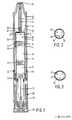
- Figure 1 is a longitudinal sectional view of a syringe according to the invention in the condition in which it can be transported and stored;
- Figure 2 is a cross-sectional view through the needle mount of the syringe of Figure 1, namely taken on the line 11-11 of Figure 1, viewed in the direction of the stopper;
- Figure 3 is a cross-sectional view through the needle mount of a syringe taken along the same line as shown in Figure 1, but this time of a different embodiment of the needle mount of the syringe in accordance with the invention;
- Figure 4 shows a different embodiment of a syringe according to the invention, partly in sideview and partly in longitudinal sectional view, in a condition wherein the syringe can be transported and stored; and
- Figure 5 is a cross-sectional view through the ampoule of the syringe of Figure 4, namely taken on the line V-V of Figure 4.
- The syringe shown in Figures 1 and 2 comprises a cylindrical
outer sleeve 11 in which acartridge assembly 12 is provided so as to be slidable, said cartridge assembly comprising a cartridge holder sleeve orinner sleeve 13 fitting in the outer sleeve, acylindrical glass ampoule 14 containing injection liquids, apiston 15 at one end and aneedle mount 16 withinjection needle 17 at the other end of the ampoule. At each end the ampoule comprises a radially outwardly projecting flange around which on the side of the injection needle the needle mount is connected by means of acollar 18. The needle holder furthermore comprises ashaft 19, which is cylindrical for the most part, and aneck 20 in which theneedle 17 covered by aflexible needle guard 21 is connected. A slot or by-pass 22 is recessed in the inner wall of the shaft and the rear wall of the neck. An externally cylindrical slidingsleeve 23 which is slidable in thecartridge holder sleeve 13 is connected around the flange at the other end of the ampoule. Thecartridge assembly 12 is provided in theouter sleeve 11 in such manner that the closed end of theneedle guard 21 bears against the end of thecartridge holder sleeve 13 having abore 24. - The
outer sleeve 11 has a length such that thecartridge assembly 12 is accommodated in one end thereof and thedischarge mechanism 25 is accommodated in the other end thereof. The discharge mechanism comprises acoil spring 26 as a power source, locking means 27 and a safety device 28. After removing the safety device, the syringe is actuated by placing the forward end of the syringe on the body of the user and exerting a backward movement ofcartridge holder sleeve 13 withcartridge assembly 12 relative toouter sleeve 11, as a result of which the locking means 27 is released and the spring is expanded. - Internally the
ampoule 14 is divided into three separatedliquid compartments cylindrical stoppers 32 and 33which, like the piston, have a slightly larger diameter than the inside diameter of the ampoule. These stoppers, as well as the piston, are manufactured from a flexible material, preferably rubber of a pharmaceutical quality. The shaft of the needle mount, apart from the by-pass, has an inside diameter which is approximately equal to, but preferably slightly largerthan that of the ampoule. Furthermore, the shaft of the needle mount is slightly longer than the two stoppers collectively, so that theend 34 of the by-pass adjoining the ampoule has just become uncovered when the stoppers are moved forward entirely to against the rear face of the neck of the needle mount. - When the syringe shown in Figures 1 and 2 is actuated, the cartridge assembly moves forward underthe influence of the spring, the sliding
sleeve 23 moving in the cartridge holder sleeve. The needle guard is compressed, the needle perforating the closed end of the needle guard and entering into the body at the point where the injection is to be administered. When the needle is in its foremost position, in which the needle mount is stopped when the front part 35 of the needle mount connecting the shaft and the neck abuts against ashoulder 36 formed by a constriction in the cartridge holder neck, the forward movement of the piston begins under the influence of the same spring, so that the actual injection is begun. The injection liquid incompartment 29 is now injected, the whole assembly ofpiston 15,stoppers liquid columns stopper 32 has moved in the shaft over a distance such that the rear of said stopper has passed theend 34 of the by-pass adjoining the ampoule, the injection liquid incompartment 30 can reach the needle via the by-pass. When all the injection liquid from thecompartments stopper 32 is positioned against the rear face of the neck of the needle mount andstoppers instant stopper 33 has moved forward over such a distance that the rear face of said stopper leaves theend 34 of the by-pass 22 adjoining the ampoule just uncovered so that the injection liquid incompartment 31 can also reach the needle and can be injected. - In another embodiment the diameter of the shaft of the needle mount is slightly larger than that of the stoppers so that the injection liquids behind the stoppers can pass the stoppers when they have been moved into the shaft. The shaft of the needle mount may have a circular or oval cross-section; the latter shape is shown in Figure 3. The rear face of the neck of the needle mount or the front face of the front stopper comprises spacing supports 37, for example, in the form of caps or truncated cones. The cross-section shown in Figure 3 is viewed in the direction of the
front stopper 32, the front face of the stopper comprising threeprojections 37. - The syringe shown in Figure 4 comprises partially the same components as the syringe shown in Figure 1. These identical parts have the same reference numbers, viz.
outer sleeve 11,cartridge assembly 12,inner sleeve 13,piston 15,needle guard 21,discharge mechanism 25,coil spring 26, locking means 27 and safety device 28. - Internally the
ampoule 44 of the syringe shown in Figure 4 is divided into two separatedliquid compartments 40 and 41 by means of acylindrical rubber stopper 42, which has a slightly larger diameter than the inside diameter of the ampoule. The front of the ampoule is sealingly provided with analuminium needle mount 43; in this needle mount the needle is sealingly connected (not shown in the Figure). Behind the rear end of the needle and sealingly closing the liquid compartment 41 towards the needle a membrane is accommodated in the needle mount. - In front of the
stopper 42, towards the needle connection, the wall of the ampoule is locally deformed. This deformation has the form of aridge 45 which extends radially inwardly in the longitudinal direction of the ampoule. This feature is more clearly visible in Figure 5, which is a cross-sectional view through the ampoule of the syringe taken on the line V-V of Figure 4, at the moment that thestopper 42 upon actuation of the syringe has been moved into the forward position. Theridge 45 is slightly longer than thestopper 42 and may be formed on the inner wall of the ampoule by locally heating the glass wall of the ampoule and depressing it. - In general the actuation of the syringe shown in Figures 4 and 5 is the same as described for the embodiments shown in Figures 1 through 3. After rupture of the membrane the injection liquid in compartment 41 is expelled through the needle. Meanwhile the
stopper 42 is pushed forward under the influence of the spring force until it abuts against ashoulder 47 of theampoule 44. As a result of the deformation of the stopper, small ducts are formed on either side of the ridge 45 (see Figure 5). The injection liquid present incompartment 40 can pass the stopper via the ducts and can thus reach the cannula and be expelled. - When the injection liquid between stopper and piston has been expelled as completely as possible, the front of the piston contacts the rear side of the stopper. It will be obvious that the front of the piston and the rear side of the stopper are substantially complementary and are preferably substantially flat faces in order to keep the residual volume of injection liquid as small as possible.
Claims (4)
Priority Applications (1)
| Application Number | Priority Date | Filing Date | Title |
|---|---|---|---|
| AT82200890TATE32432T1 (en) | 1981-08-10 | 1982-07-13 | AUTOMATIC INJECTION SYRINGE. |
Applications Claiming Priority (2)
| Application Number | Priority Date | Filing Date | Title |
|---|---|---|---|
| NL8103744 | 1981-08-10 | ||
| NL8103744 | 1981-08-10 |
Publications (2)
| Publication Number | Publication Date |
|---|---|
| EP0072057A1 EP0072057A1 (en) | 1983-02-16 |
| EP0072057B1true EP0072057B1 (en) | 1988-02-10 |
Family
ID=19837908
Family Applications (1)
| Application Number | Title | Priority Date | Filing Date |
|---|---|---|---|
| EP82200890AExpiredEP0072057B1 (en) | 1981-08-10 | 1982-07-13 | Automatic injection syringe |
Country Status (17)
| Country | Link |
|---|---|
| US (3) | US4529403A (en) |
| EP (1) | EP0072057B1 (en) |
| JP (1) | JPS5841568A (en) |
| KR (1) | KR880001422B1 (en) |
| AR (1) | AR228514A1 (en) |
| AT (1) | ATE32432T1 (en) |
| AU (1) | AU560657B2 (en) |
| BR (1) | BR8204634A (en) |
| CA (1) | CA1183420A (en) |
| DE (1) | DE3278101D1 (en) |
| DK (1) | DK159809C (en) |
| ES (2) | ES273695Y (en) |
| HK (1) | HK66188A (en) |
| IE (1) | IE53494B1 (en) |
| IL (1) | IL66499A (en) |
| PH (1) | PH22781A (en) |
| ZA (1) | ZA825678B (en) |
Cited By (7)
| Publication number | Priority date | Publication date | Assignee | Title |
|---|---|---|---|---|
| US8915889B2 (en) | 2008-08-05 | 2014-12-23 | Antares Pharma, Inc. | Multiple dosage injector |
| US8945063B2 (en) | 2009-03-20 | 2015-02-03 | Antares Pharma, Inc. | Hazardous agent injection system |
| US9180259B2 (en) | 2005-01-24 | 2015-11-10 | Antares Pharma, Inc. | Prefilled syringe jet injector |
| US9220660B2 (en) | 2011-07-15 | 2015-12-29 | Antares Pharma, Inc. | Liquid-transfer adapter beveled spike |
| US9333309B2 (en) | 2002-02-11 | 2016-05-10 | Antares Pharma, Inc. | Intradermal injector |
| US9364610B2 (en) | 2012-05-07 | 2016-06-14 | Antares Pharma, Inc. | Injection device with cammed ram assembly |
| US9446195B2 (en) | 2011-07-15 | 2016-09-20 | Antares Pharma, Inc. | Injection device with cammed ram assembly |
Families Citing this family (84)
| Publication number | Priority date | Publication date | Assignee | Title |
|---|---|---|---|---|
| DE3662752D1 (en)* | 1985-02-07 | 1989-05-18 | Duphar Int Res | Syringe |
| US4723937A (en)* | 1985-05-20 | 1988-02-09 | Survival Technology, Inc. | Plural dosage automatic injector with a by-pass fitment |
| DE3673317D1 (en)* | 1985-10-11 | 1990-09-13 | Duphar Int Res | AUTOMATIC SYRINGE. |
| ATE67414T1 (en)* | 1986-05-15 | 1991-10-15 | Duphar Int Res | AUTOMATIC INJECTION SYRINGE. |
| US4781701A (en)* | 1986-07-11 | 1988-11-01 | Arzneimittel Gmbh Apotheker Vetter & Co. Ravensburg | Syringe for medical purposes |
| US4838862A (en)* | 1986-08-04 | 1989-06-13 | Pharmetrix Corp. | Portable controlled release osmotic infusion device |
| US4743229A (en)* | 1986-09-29 | 1988-05-10 | Collagen Corporation | Collagen/mineral mixing device and method |
| SE457417B (en)* | 1987-04-14 | 1988-12-27 | Astra Meditec Ab | AUTOMATIC SQUARE SPRAY, PROCEDURE FOR MIXING AND INJECTION WITH THE SPRAYER AND AMPULA FOR PRIVATE CHAMBER SPRAY |
| USD304616S (en) | 1987-04-30 | 1989-11-14 | Derata Corporation | Medicament injector |
| AU595096B2 (en)* | 1988-02-10 | 1990-03-22 | Astra Pharmaceuticals Pty Ltd | Plastic cartridge and syringe |
| US4932944A (en)* | 1988-03-09 | 1990-06-12 | The University Of Virginia Alumni Patents Foundation | Intravenous port injection and connector system |
| US4929230A (en)* | 1988-09-30 | 1990-05-29 | Pfleger Frederick W | Syringe construction |
| US5026349A (en)* | 1988-10-05 | 1991-06-25 | Autoject Systems Inc. | Liquid medicament injector system |
| ES2036885T3 (en)* | 1989-03-28 | 1993-06-01 | Duphar International Research B.V | A PRE-LOADED INJECTION DEVICE COMPRISING A CYLINDRICAL BODY IN WHICH A LIQUID FORMULATION OF DIAZEPAM IS ACCOMMODATED. |
| US5085641A (en)* | 1989-07-17 | 1992-02-04 | Survival Technology, Inc. | Conveniently carried frequent use auto-injector with improved cap structure |
| US5092843A (en)* | 1990-04-12 | 1992-03-03 | Survival Technology, Inc. | Dispersion multichamber auto-injector |
| US5114411A (en)* | 1990-11-19 | 1992-05-19 | Habley Medical Technology Corporation | Multi-chamber vial |
| EP0518416A1 (en)* | 1991-06-13 | 1992-12-16 | Duphar International Research B.V | Injection device |
| GB9118204D0 (en)* | 1991-08-23 | 1991-10-09 | Weston Terence E | Needle-less injector |
| US5425715A (en)* | 1993-08-05 | 1995-06-20 | Survival Technology, Inc. | Reloadable injector |
| AUPO723997A0 (en)* | 1997-06-10 | 1997-07-03 | Astra Pharmaceuticals Pty Ltd | Prefilled container |
| US5865804A (en)* | 1997-07-16 | 1999-02-02 | Bachynsky; Nicholas | Rotary cam syringe |
| US5971953A (en)* | 1998-01-09 | 1999-10-26 | Bachynsky; Nicholas | Dual chamber syringe apparatus |
| US6149626A (en)* | 1997-10-03 | 2000-11-21 | Bachynsky; Nicholas | Automatic injecting syringe apparatus |
| ES2140328B1 (en)* | 1997-12-04 | 2000-10-16 | Perez Jose Manuel Prieto | APPLICATOR DEVICE FOR AMPOULES OF INJECTABLE THERAPEUTIC SUBSTANCES. |
| ATE381361T1 (en)* | 1999-10-22 | 2008-01-15 | Antares Pharma Inc | MEDICATION CARTRIDGE AND INJECTION DEVICE |
| JP2003534879A (en) | 2000-06-08 | 2003-11-25 | メリディアン メディカル テクノロジーズ,インコーポレイテッド | Wet / dry automatic injection assembly |
| US6517517B1 (en) | 2000-06-08 | 2003-02-11 | Mayo Foundation For Medical Education And Research | Automated injection device for administration of liquid medicament |
| DE10036594A1 (en) | 2000-07-27 | 2002-02-07 | Pfeiffer Erich Gmbh & Co Kg | Delivery unit, especially for pharmaceuticals, comprises a container composed of separate chambers which hold a media component, an actuating unit and a connection between the chambers |
| JP4626064B2 (en)* | 2000-09-28 | 2011-02-02 | 生化学工業株式会社 | Syringe |
| US6953445B2 (en)* | 2000-10-10 | 2005-10-11 | Meridian Medical Technologies, Inc. | Wet/dry automatic injector assembly |
| US6770052B2 (en)* | 2000-10-10 | 2004-08-03 | Meridian Medical Technologies, Inc. | Wet/dry automatic injector assembly |
| US7556614B2 (en)* | 2000-10-10 | 2009-07-07 | Meridian Medical Technologies, Inc. | Separation assembly for drug delivery device |
| US6641561B1 (en) | 2000-10-10 | 2003-11-04 | Meridian Medical Technologies, Inc. | Drug delivery device |
| US6656150B2 (en) | 2000-10-10 | 2003-12-02 | Meridian Medical Technologies, Inc. | Wet/dry automatic injector assembly |
| US7621887B2 (en)* | 2000-10-10 | 2009-11-24 | Meridian Medical Technologies, Inc. | Wet/dry automatic injector assembly |
| US7544189B2 (en)* | 2000-10-10 | 2009-06-09 | Meridian Medical Technologies, Inc. | Needle and hub assembly for automatic injector |
| DE10051371A1 (en)* | 2000-10-17 | 2002-06-06 | Disetronic Licensing Ag | Device for the dosed administration of an injectable product |
| GB0118419D0 (en)* | 2001-07-28 | 2001-09-19 | Owen Mumford Ltd | Improvements relating to injection devices |
| DE10146535C2 (en)* | 2001-09-21 | 2003-08-14 | Buender Glas Gmbh | Needle-less syringe |
| US20030105433A1 (en)* | 2001-11-30 | 2003-06-05 | Ruben Philip H. | Disposable syringe and cartridge with pneumatic chamber |
| US6866653B2 (en)* | 2002-10-31 | 2005-03-15 | Kyongtae T. Bae | Method and apparatus for sequential delivery of multiple injectable substances stored in a prefilled syringe |
| ATE306957T1 (en)* | 2003-02-24 | 2005-11-15 | Buender Glas Gmbh | NEEDLELESS SYRINGE |
| IL157981A (en) | 2003-09-17 | 2014-01-30 | Elcam Medical Agricultural Cooperative Ass Ltd | Auto-injector |
| IL160891A0 (en) | 2004-03-16 | 2004-08-31 | Auto-mix needle | |
| US20050273054A1 (en)* | 2004-06-03 | 2005-12-08 | Florida Atlantic University | Epinephrine auto-injector |
| US7637175B1 (en)* | 2004-08-26 | 2009-12-29 | Elemental Scientific, Inc. | Automated sampling device |
| US7690275B1 (en) | 2004-08-26 | 2010-04-06 | Elemental Scientific, Inc. | Automated sampling device |
| US20060178638A1 (en)* | 2004-12-03 | 2006-08-10 | Reynolds David L | Device and method for pharmaceutical mixing and delivery |
| JP2006198143A (en)* | 2005-01-20 | 2006-08-03 | Arte Corp | Syringe used in common as container |
| JP4682850B2 (en)* | 2006-01-12 | 2011-05-11 | ニプロ株式会社 | Prefilled syringe |
| WO2007131013A1 (en) | 2006-05-03 | 2007-11-15 | Antares Pharma, Inc. | Two-stage reconstituting injector |
| JP2008099728A (en)* | 2006-10-17 | 2008-05-01 | Arte Corp | Syringe serving also as container |
| US7811254B2 (en)* | 2006-10-18 | 2010-10-12 | Meridian Medical Technologies, Inc. | Autoinjector with needle depth adapter |
| BRPI0820317B8 (en)* | 2007-11-22 | 2021-06-22 | Biovitrum Ab Publ | method and device for the serial ejection of two fluids comprising a separator |
| TWI395593B (en) | 2008-03-06 | 2013-05-11 | Halozyme Inc | In vivo temporal control of activatable matrix-degrading enzymes |
| TWI555546B (en)* | 2008-12-02 | 2016-11-01 | 賽諾菲阿凡提斯德意志有限公司 | Medication delivery device and method for operating a medication delivery device |
| WO2010102262A1 (en) | 2009-03-06 | 2010-09-10 | Halozyme, Inc. | Temperature sensitive mutants of matrix metalloprotease 1 und uses thereof |
| US20100318063A1 (en)* | 2009-06-10 | 2010-12-16 | Cleo Cosmetic And Pharmaceuticals Co., Llc | Dual barrel syringe assembly |
| US10350364B2 (en) | 2009-11-11 | 2019-07-16 | Windgap Medical, Inc. | Portable Drug Mixing and Delivery Device and Associated Methods |
| JP2014510045A (en) | 2011-02-08 | 2014-04-24 | ハロザイム インコーポレイテッド | Hyaluronan degrading enzyme composition and lipid preparation and its use for the treatment of benign prostatic hypertrophy |
| DE102011013792A1 (en) | 2011-03-03 | 2012-09-06 | Vetter Pharma-Fertigung GmbH & Co. KG | Closure for a powder syringe and powder syringe |
| WO2013040501A1 (en) | 2011-09-16 | 2013-03-21 | Pharmathene, Inc. | Compositions and combinations of organophosphorus bioscavengers and hyaluronan-degrading enzymes, and uses thereof |
| EP4186545A1 (en) | 2012-04-06 | 2023-05-31 | Antares Pharma, Inc. | Needle assisted jet injection administration of testosterone compositions |
| US9341229B1 (en) | 2012-09-10 | 2016-05-17 | Elemental Scientific, Inc. | Automated sampling device |
| WO2014093926A1 (en)* | 2012-12-14 | 2014-06-19 | Larson Bryan | Dual medicament carpule for dental syringes |
| FI3659647T3 (en) | 2013-02-11 | 2024-03-28 | Antares Pharma Inc | NEEDLE-ASSISTED SPRAY INJECTOR WITH REDUCED TRIGGER FORCE |
| CA2905031C (en) | 2013-03-11 | 2018-01-23 | Hans PFLAUMER | Dosage injector with pinion system |
| US10569017B2 (en) | 2013-03-15 | 2020-02-25 | Windgap Medical, Inc. | Portable drug mixing and delivery device and associated methods |
| US10391262B2 (en) | 2014-03-18 | 2019-08-27 | Windgap Medical, Inc. | Removable actuating cap for use with an auto-injector assembly |
| US9907910B2 (en) | 2013-03-15 | 2018-03-06 | Windgap Medical, Inc. | Portable drug mixing and delivery device and associated methods |
| JP6560187B2 (en) | 2013-03-15 | 2019-08-14 | ウインドギャップ メディカル インコーポレイテッド | Portable drug mixing and delivery system and method |
| US11116903B2 (en) | 2014-08-18 | 2021-09-14 | Windgap Medical, Inc | Compression seal for use with a liquid component storage vial of an auto-injector |
| CA2994803C (en) | 2014-08-18 | 2023-09-12 | Windgap Medical, Inc. | Portable drug mixing and delivery device and associated methods |
| CA2994300C (en) | 2015-08-13 | 2023-12-05 | Windgap Medical, Inc. | Mixing and injection device with sterility features |
| US9579453B1 (en) | 2016-02-18 | 2017-02-28 | Chalbourne Brasington | Two-step auto-injection device |
| WO2018125629A1 (en) | 2016-12-27 | 2018-07-05 | Action Medical Technologies, Llc | Apparatuses and method for injecting medicaments |
| US10245381B2 (en) | 2017-08-21 | 2019-04-02 | Chalbourne Brasington | Two-step auto-injection device |
| WO2020014292A1 (en) | 2018-07-10 | 2020-01-16 | Action Medical Technologies, Llc | Apparatuses and method for injecting medicaments |
| USD893712S1 (en) | 2019-02-15 | 2020-08-18 | Action Medical Technologies, Llc | Grip for autoinjectors |
| US20200353174A1 (en)* | 2019-05-09 | 2020-11-12 | Aurobindo Pharma Ltd | Pen injector with drive member and reducer arm set |
| US11065392B1 (en) | 2020-03-25 | 2021-07-20 | Action Medical Technologies, Llc | Apparatuses and methods for injecting medicaments |
| US12311147B2 (en)* | 2020-04-17 | 2025-05-27 | Becton, Dickinson And Company | Dual chamber syringe assembly |
| US11759576B2 (en) | 2020-06-05 | 2023-09-19 | Action Medical Technologies, Llc | Parenteral injection apparatus |
Family Cites Families (17)
| Publication number | Priority date | Publication date | Assignee | Title |
|---|---|---|---|---|
| US2591046A (en)* | 1948-10-18 | 1952-04-01 | Frederick M Turnbull | Hypodermic syringe assembly |
| US2717601A (en)* | 1949-08-10 | 1955-09-13 | Frederick M Turnbull | Syringe ampule |
| US3058467A (en)* | 1958-10-27 | 1962-10-16 | Faure Jean-Marie | Hypodermic syringes |
| US3330282A (en)* | 1964-08-21 | 1967-07-11 | Upjohn Co | Combination syringe and vial mixing container |
| BE755165A (en)* | 1969-08-23 | 1971-02-22 | Philips Nv | ELASTICALLY DEFORMABLE PLUG FOR INJECTION SYRINGE |
| JPS4914465Y1 (en)* | 1969-10-13 | 1974-04-10 | ||
| FR2110516A5 (en)* | 1970-10-20 | 1972-06-02 | Blanchet Henry | Two compartment automatic syringe - for multiple inoculation |
| US3881484A (en)* | 1973-07-05 | 1975-05-06 | Jr Charles F Gidcumb | Mixing syringe having a rotationally restrained piston rod |
| US3882863A (en)* | 1973-08-01 | 1975-05-13 | Survival Technology | Hypodermic injection device having cannula covered with resilient sheath |
| US3914419A (en)* | 1973-08-02 | 1975-10-21 | American Cyanamid Co | Two compartment one unit consecutively injectable liquid vitamin package |
| US4031893A (en)* | 1976-05-14 | 1977-06-28 | Survival Technology, Inc. | Hypodermic injection device having means for varying the medicament capacity thereof |
| NL180634C (en)* | 1977-12-23 | 1987-04-01 | Duphar Int Res | INJECTION SYRINGE AND NEEDLE HOLDER FOR THIS. |
| JPS5575335U (en)* | 1978-11-14 | 1980-05-24 | ||
| US4226235A (en)* | 1979-01-25 | 1980-10-07 | Survival Technology, Inc. | Plural injecting device |
| ATE15861T1 (en)* | 1981-07-29 | 1985-10-15 | Duphar Int Res | INJECTION SYRINGE. |
| US4394863A (en)* | 1981-10-23 | 1983-07-26 | Survival Technology, Inc. | Automatic injector with cartridge having separate sequentially injectable medicaments |
| US4413991A (en)* | 1982-03-18 | 1983-11-08 | Schmitz John B | Dual dose ampule |
- 1982
- 1982-07-13ATAT82200890Tpatent/ATE32432T1/ennot_activeIP Right Cessation
- 1982-07-13EPEP82200890Apatent/EP0072057B1/ennot_activeExpired
- 1982-07-13DEDE8282200890Tpatent/DE3278101D1/ennot_activeExpired
- 1982-08-05ZAZA825678Apatent/ZA825678B/enunknown
- 1982-08-05AUAU86779/82Apatent/AU560657B2/ennot_activeCeased
- 1982-08-05USUS06/405,367patent/US4529403A/ennot_activeExpired - Lifetime
- 1982-08-05ARAR290231Apatent/AR228514A1/enactive
- 1982-08-06CACA000408862Apatent/CA1183420A/ennot_activeExpired
- 1982-08-06IEIE1908/82Apatent/IE53494B1/ennot_activeIP Right Cessation
- 1982-08-06BRBR8204634Apatent/BR8204634A/ennot_activeIP Right Cessation
- 1982-08-06ESES1982273695Upatent/ES273695Y/ennot_activeExpired
- 1982-08-06DKDK354882Apatent/DK159809C/ennot_activeIP Right Cessation
- 1982-08-07KRKR8203566Apatent/KR880001422B1/ennot_activeExpired
- 1982-08-09JPJP57137448Apatent/JPS5841568A/enactiveGranted
- 1982-08-09ILIL66499Apatent/IL66499A/ennot_activeIP Right Cessation
- 1982-08-10PHPH27705Apatent/PH22781A/enunknown
- 1983
- 1983-12-13USUS06/560,925patent/US4573971A/ennot_activeExpired - Fee Related
- 1983-12-13USUS06/560,935patent/US4573972A/ennot_activeExpired - Fee Related
- 1983-12-30ESES1983276633Upatent/ES276633Y/ennot_activeExpired
- 1988
- 1988-08-25HKHK661/88Apatent/HK66188A/ennot_activeIP Right Cessation
Cited By (8)
| Publication number | Priority date | Publication date | Assignee | Title |
|---|---|---|---|---|
| US9333309B2 (en) | 2002-02-11 | 2016-05-10 | Antares Pharma, Inc. | Intradermal injector |
| US9180259B2 (en) | 2005-01-24 | 2015-11-10 | Antares Pharma, Inc. | Prefilled syringe jet injector |
| US8915889B2 (en) | 2008-08-05 | 2014-12-23 | Antares Pharma, Inc. | Multiple dosage injector |
| US8945063B2 (en) | 2009-03-20 | 2015-02-03 | Antares Pharma, Inc. | Hazardous agent injection system |
| US9220660B2 (en) | 2011-07-15 | 2015-12-29 | Antares Pharma, Inc. | Liquid-transfer adapter beveled spike |
| US9446195B2 (en) | 2011-07-15 | 2016-09-20 | Antares Pharma, Inc. | Injection device with cammed ram assembly |
| US9364610B2 (en) | 2012-05-07 | 2016-06-14 | Antares Pharma, Inc. | Injection device with cammed ram assembly |
| US9364611B2 (en) | 2012-05-07 | 2016-06-14 | Antares Pharma, Inc. | Needle assisted jet injection device having reduced trigger force |
Also Published As
| Publication number | Publication date |
|---|---|
| DK159809B (en) | 1990-12-10 |
| ZA825678B (en) | 1983-06-29 |
| ES276633U (en) | 1984-05-16 |
| PH22781A (en) | 1988-12-12 |
| ES273695U (en) | 1984-04-01 |
| US4529403A (en) | 1985-07-16 |
| US4573972A (en) | 1986-03-04 |
| ES276633Y (en) | 1984-12-16 |
| BR8204634A (en) | 1984-03-13 |
| JPS5841568A (en) | 1983-03-10 |
| EP0072057A1 (en) | 1983-02-16 |
| CA1183420A (en) | 1985-03-05 |
| IE821908L (en) | 1983-02-10 |
| ATE32432T1 (en) | 1988-02-15 |
| DK159809C (en) | 1991-05-06 |
| IL66499A0 (en) | 1982-12-31 |
| JPH0460673B2 (en) | 1992-09-28 |
| AR228514A1 (en) | 1983-03-15 |
| DE3278101D1 (en) | 1988-03-17 |
| ES273695Y (en) | 1984-11-16 |
| US4573971A (en) | 1986-03-04 |
| AU560657B2 (en) | 1987-04-16 |
| DK354882A (en) | 1983-02-11 |
| AU8677982A (en) | 1983-02-17 |
| HK66188A (en) | 1988-09-02 |
| KR880001422B1 (en) | 1988-08-08 |
| IL66499A (en) | 1986-11-30 |
| IE53494B1 (en) | 1988-11-23 |
| KR840000910A (en) | 1984-03-26 |
Similar Documents
| Publication | Publication Date | Title |
|---|---|---|
| EP0072057B1 (en) | Automatic injection syringe | |
| US4394863A (en) | Automatic injector with cartridge having separate sequentially injectable medicaments | |
| EP0525048B1 (en) | Dispersion multi-chamber auto-injector | |
| AU639955B2 (en) | An administering device | |
| US4822340A (en) | Automatic injector | |
| US5360410A (en) | Safety syringe for mixing two-component medicaments | |
| US5383864A (en) | Pre-filled injection device comprising a barrel wherein a liquid diazepam formulation is accommodated | |
| US5695472A (en) | Modular automatic or manual emergency medicine injection system | |
| EP0014006B1 (en) | Automatic, plural spring actuated, injecting device | |
| EP0700307B1 (en) | Reloadable automatic or manual emergency injection system | |
| US5496284A (en) | Dual-chamber syringe & method | |
| US4723937A (en) | Plural dosage automatic injector with a by-pass fitment | |
| US5425715A (en) | Reloadable injector | |
| EP0518416A1 (en) | Injection device | |
| US2726656A (en) | Hypodermic syringe structure | |
| HU182036B (en) | Injection syringe as well as needle holder and recipient belonging same | |
| US4447231A (en) | Automatic injection syringe | |
| US5364363A (en) | Rectal administrator | |
| EP0461693A1 (en) | Flexible sealing member for injection device | |
| KR830001832B1 (en) | Multiple injection device |
Legal Events
| Date | Code | Title | Description |
|---|---|---|---|
| PUAI | Public reference made under article 153(3) epc to a published international application that has entered the european phase | Free format text:ORIGINAL CODE: 0009012 | |
| AK | Designated contracting states | Designated state(s):AT BE CH DE FR GB IT LI NL SE | |
| 17P | Request for examination filed | Effective date:19830708 | |
| GRAA | (expected) grant | Free format text:ORIGINAL CODE: 0009210 | |
| AK | Designated contracting states | Kind code of ref document:B1 Designated state(s):AT BE CH DE FR GB IT LI NL SE | |
| REF | Corresponds to: | Ref document number:32432 Country of ref document:AT Date of ref document:19880215 Kind code of ref document:T | |
| ITF | It: translation for a ep patent filed | ||
| REF | Corresponds to: | Ref document number:3278101 Country of ref document:DE Date of ref document:19880317 | |
| ET | Fr: translation filed | ||
| PLBE | No opposition filed within time limit | Free format text:ORIGINAL CODE: 0009261 | |
| STAA | Information on the status of an ep patent application or granted ep patent | Free format text:STATUS: NO OPPOSITION FILED WITHIN TIME LIMIT | |
| 26N | No opposition filed | ||
| ITTA | It: last paid annual fee | ||
| PGFP | Annual fee paid to national office [announced via postgrant information from national office to epo] | Ref country code:AT Payment date:19930617 Year of fee payment:12 | |
| PGFP | Annual fee paid to national office [announced via postgrant information from national office to epo] | Ref country code:BE Payment date:19930629 Year of fee payment:12 | |
| PGFP | Annual fee paid to national office [announced via postgrant information from national office to epo] | Ref country code:NL Payment date:19930731 Year of fee payment:12 | |
| PG25 | Lapsed in a contracting state [announced via postgrant information from national office to epo] | Ref country code:AT Effective date:19940713 | |
| PG25 | Lapsed in a contracting state [announced via postgrant information from national office to epo] | Ref country code:BE Effective date:19940731 | |
| BERE | Be: lapsed | Owner name:DUPHAR INTERNATIONAL RESEARCH B.V. Effective date:19940731 | |
| EAL | Se: european patent in force in sweden | Ref document number:82200890.0 | |
| PG25 | Lapsed in a contracting state [announced via postgrant information from national office to epo] | Ref country code:NL Effective date:19950201 | |
| NLV4 | Nl: lapsed or anulled due to non-payment of the annual fee | ||
| PGFP | Annual fee paid to national office [announced via postgrant information from national office to epo] | Ref country code:SE Payment date:19970619 Year of fee payment:16 | |
| PGFP | Annual fee paid to national office [announced via postgrant information from national office to epo] | Ref country code:FR Payment date:19970620 Year of fee payment:16 | |
| PGFP | Annual fee paid to national office [announced via postgrant information from national office to epo] | Ref country code:DE Payment date:19970624 Year of fee payment:16 Ref country code:CH Payment date:19970624 Year of fee payment:16 | |
| PGFP | Annual fee paid to national office [announced via postgrant information from national office to epo] | Ref country code:GB Payment date:19970626 Year of fee payment:16 | |
| PG25 | Lapsed in a contracting state [announced via postgrant information from national office to epo] | Ref country code:GB Free format text:LAPSE BECAUSE OF NON-PAYMENT OF DUE FEES Effective date:19980713 | |
| PG25 | Lapsed in a contracting state [announced via postgrant information from national office to epo] | Ref country code:SE Free format text:LAPSE BECAUSE OF NON-PAYMENT OF DUE FEES Effective date:19980714 | |
| PG25 | Lapsed in a contracting state [announced via postgrant information from national office to epo] | Ref country code:LI Free format text:LAPSE BECAUSE OF NON-PAYMENT OF DUE FEES Effective date:19980731 Ref country code:CH Free format text:LAPSE BECAUSE OF NON-PAYMENT OF DUE FEES Effective date:19980731 | |
| GBPC | Gb: european patent ceased through non-payment of renewal fee | Effective date:19980713 | |
| REG | Reference to a national code | Ref country code:CH Ref legal event code:PL | |
| EUG | Se: european patent has lapsed | Ref document number:82200890.0 | |
| PG25 | Lapsed in a contracting state [announced via postgrant information from national office to epo] | Ref country code:FR Free format text:LAPSE BECAUSE OF NON-PAYMENT OF DUE FEES Effective date:19990331 | |
| PG25 | Lapsed in a contracting state [announced via postgrant information from national office to epo] | Ref country code:DE Free format text:LAPSE BECAUSE OF NON-PAYMENT OF DUE FEES Effective date:19990501 | |
| REG | Reference to a national code | Ref country code:FR Ref legal event code:ST |