EP0070626B1 - Medical electrode - Google Patents
Medical electrodeDownload PDFInfo
- Publication number
- EP0070626B1 EP0070626B1EP82303258AEP82303258AEP0070626B1EP 0070626 B1EP0070626 B1EP 0070626B1EP 82303258 AEP82303258 AEP 82303258AEP 82303258 AEP82303258 AEP 82303258AEP 0070626 B1EP0070626 B1EP 0070626B1
- Authority
- EP
- European Patent Office
- Prior art keywords
- sheet
- web
- release liner
- opening
- electrode
- Prior art date
- Legal status (The legal status is an assumption and is not a legal conclusion. Google has not performed a legal analysis and makes no representation as to the accuracy of the status listed.)
- Expired
Links
- 238000005520cutting processMethods0.000claimsdescription29
- 238000004519manufacturing processMethods0.000claimsdescription17
- 238000000034methodMethods0.000claimsdescription13
- 239000000853adhesiveSubstances0.000claimsdescription12
- 230000001070adhesive effectEffects0.000claimsdescription12
- 238000010030laminatingMethods0.000claimsdescription7
- 239000000463materialSubstances0.000claimsdescription5
- 238000003780insertionMethods0.000claimsdescription3
- 230000037431insertionEffects0.000claimsdescription3
- 238000003475laminationMethods0.000description12
- 239000000499gelSubstances0.000description10
- 239000006260foamSubstances0.000description4
- 238000007789sealingMethods0.000description3
- 239000006261foam materialSubstances0.000description2
- 230000014759maintenance of locationEffects0.000description2
- 229920003023plasticPolymers0.000description2
- 239000004033plasticSubstances0.000description2
- 229910021607Silver chlorideInorganic materials0.000description1
- 238000004140cleaningMethods0.000description1
- 230000000593degrading effectEffects0.000description1
- 239000012467final productSubstances0.000description1
- 235000015110jelliesNutrition0.000description1
- 239000008274jellySubstances0.000description1
- 239000011159matrix materialSubstances0.000description1
- 238000012544monitoring processMethods0.000description1
- 230000000704physical effectEffects0.000description1
- 229920006267polyester filmPolymers0.000description1
- 229920001296polysiloxanePolymers0.000description1
- 238000002360preparation methodMethods0.000description1
- 229910052709silverInorganic materials0.000description1
- 239000004332silverSubstances0.000description1
- HKZLPVFGJNLROG-UHFFFAOYSA-Msilver monochlorideChemical compound[Cl-].[Ag+]HKZLPVFGJNLROG-UHFFFAOYSA-M0.000description1
- 125000000391vinyl groupChemical group[H]C([*])=C([H])[H]0.000description1
- 229920002554vinyl polymerPolymers0.000description1
- 239000002699waste materialSubstances0.000description1
Images

Classifications
- B—PERFORMING OPERATIONS; TRANSPORTING
- B32—LAYERED PRODUCTS
- B32B—LAYERED PRODUCTS, i.e. PRODUCTS BUILT-UP OF STRATA OF FLAT OR NON-FLAT, e.g. CELLULAR OR HONEYCOMB, FORM
- B32B7/00—Layered products characterised by the relation between layers; Layered products characterised by the relative orientation of features between layers, or by the relative values of a measurable parameter between layers, i.e. products comprising layers having different physical, chemical or physicochemical properties; Layered products characterised by the interconnection of layers
- B32B7/04—Interconnection of layers
- B32B7/06—Interconnection of layers permitting easy separation
- B—PERFORMING OPERATIONS; TRANSPORTING
- B32—LAYERED PRODUCTS
- B32B—LAYERED PRODUCTS, i.e. PRODUCTS BUILT-UP OF STRATA OF FLAT OR NON-FLAT, e.g. CELLULAR OR HONEYCOMB, FORM
- B32B33/00—Layered products characterised by particular properties or particular surface features, e.g. particular surface coatings; Layered products designed for particular purposes not covered by another single class
- A—HUMAN NECESSITIES
- A61—MEDICAL OR VETERINARY SCIENCE; HYGIENE
- A61B—DIAGNOSIS; SURGERY; IDENTIFICATION
- A61B5/00—Measuring for diagnostic purposes; Identification of persons
- A61B5/24—Detecting, measuring or recording bioelectric or biomagnetic signals of the body or parts thereof
- A61B5/25—Bioelectric electrodes therefor
- A61B5/251—Means for maintaining electrode contact with the body
- A61B5/257—Means for maintaining electrode contact with the body using adhesive means, e.g. adhesive pads or tapes
- A—HUMAN NECESSITIES
- A61—MEDICAL OR VETERINARY SCIENCE; HYGIENE
- A61B—DIAGNOSIS; SURGERY; IDENTIFICATION
- A61B5/00—Measuring for diagnostic purposes; Identification of persons
- A61B5/24—Detecting, measuring or recording bioelectric or biomagnetic signals of the body or parts thereof
- A61B5/25—Bioelectric electrodes therefor
- A61B5/263—Bioelectric electrodes therefor characterised by the electrode materials
- A61B5/266—Bioelectric electrodes therefor characterised by the electrode materials containing electrolytes, conductive gels or pastes
- A—HUMAN NECESSITIES
- A61—MEDICAL OR VETERINARY SCIENCE; HYGIENE
- A61B—DIAGNOSIS; SURGERY; IDENTIFICATION
- A61B5/00—Measuring for diagnostic purposes; Identification of persons
- A61B5/24—Detecting, measuring or recording bioelectric or biomagnetic signals of the body or parts thereof
- A61B5/25—Bioelectric electrodes therefor
- A61B5/271—Arrangements of electrodes with cords, cables or leads, e.g. single leads or patient cord assemblies
- A61B5/273—Connection of cords, cables or leads to electrodes
- B—PERFORMING OPERATIONS; TRANSPORTING
- B32—LAYERED PRODUCTS
- B32B—LAYERED PRODUCTS, i.e. PRODUCTS BUILT-UP OF STRATA OF FLAT OR NON-FLAT, e.g. CELLULAR OR HONEYCOMB, FORM
- B32B7/00—Layered products characterised by the relation between layers; Layered products characterised by the relative orientation of features between layers, or by the relative values of a measurable parameter between layers, i.e. products comprising layers having different physical, chemical or physicochemical properties; Layered products characterised by the interconnection of layers
- B32B7/04—Interconnection of layers
- B32B7/12—Interconnection of layers using interposed adhesives or interposed materials with bonding properties
- A—HUMAN NECESSITIES
- A61—MEDICAL OR VETERINARY SCIENCE; HYGIENE
- A61B—DIAGNOSIS; SURGERY; IDENTIFICATION
- A61B2562/00—Details of sensors; Constructional details of sensor housings or probes; Accessories for sensors
- A61B2562/12—Manufacturing methods specially adapted for producing sensors for in-vivo measurements
- A61B2562/125—Manufacturing methods specially adapted for producing sensors for in-vivo measurements characterised by the manufacture of electrodes
- B—PERFORMING OPERATIONS; TRANSPORTING
- B32—LAYERED PRODUCTS
- B32B—LAYERED PRODUCTS, i.e. PRODUCTS BUILT-UP OF STRATA OF FLAT OR NON-FLAT, e.g. CELLULAR OR HONEYCOMB, FORM
- B32B2535/00—Medical equipment, e.g. bandage, prostheses or catheter
- Y—GENERAL TAGGING OF NEW TECHNOLOGICAL DEVELOPMENTS; GENERAL TAGGING OF CROSS-SECTIONAL TECHNOLOGIES SPANNING OVER SEVERAL SECTIONS OF THE IPC; TECHNICAL SUBJECTS COVERED BY FORMER USPC CROSS-REFERENCE ART COLLECTIONS [XRACs] AND DIGESTS
- Y10—TECHNICAL SUBJECTS COVERED BY FORMER USPC
- Y10T—TECHNICAL SUBJECTS COVERED BY FORMER US CLASSIFICATION
- Y10T29/00—Metal working
- Y10T29/49—Method of mechanical manufacture
- Y10T29/49002—Electrical device making
- Y10T29/49117—Conductor or circuit manufacturing
Definitions
- This inventionrelates to disposable medical electrodes, and a method for making the same, and more particularly to disposable electrocardiogram electrodes.
- Electrodeshave been developed through which electrical contact with the human body can be made. These electrodes are either permanent (i.e. reusable) electrodes, or disposable electrodes which are utilized only for a single patient and then discarded.
- the disposable electrodeshave largely resulted from attempts to reduce the costs involved in the upkeep and cleaning of the permanent electrode between uses, as well as the patient and electrode preparation required prior to each use of the permanent electrodes. Such cost reduction attempts, however, have necessarily been tempered to ensure that the integrity and quality of the electrical contact established by the electrode was not sacrificed.
- the existing electrodesgenerally incorporated an integral and centralized cup-like cavity in which the conductive gel was restrained and sealed (see e.g. U.S. Patent No. 4,126,126), and which had an adhesive coated flange-like projection extending outward from the side of the cavity to attach the electrode to the human body.
- the existing electrodestypically had the configuration of a disk with all of the electrode's components centrally mounted thereon. This configuration, although allowing a partially automated manufacturing process, still required substantial manual interface to critically align the various components forming the electrode.
- a method of manufacturing disposable medical electrodes as defined in claim 1comprising the steps of: cutting a plurality of openings along a first web of an adhesive coated material, with at least one opening at each of a plurality of predetermined locations which are longitudinally spaced from each other, laminating a release linear web to the adhesive coated surface of the first web, thereby defining a reservoir bordered by the release liner and the periphery of the opening, introducing a conductive gel into the reservoir, cutting a plurality of holes along a second web with at least one hole at each of a plurality of predetermined locations which are spaced longitudinally from each other, laminating the second web to the surface of the first web opposite the surface laminated to the release liner, with the holes in the second web generally centrally positioned over the openings in the first web, and with the second web covering and extending beyond each of the openings, laminating a third web to the surface of the second web opposite the surface laminated to the first web, with the
- the release liner webmay be laminated to the adhesive coated surface of the first web prior to cutting of the plurality of opening along the first web as defined in claim 6.
- the electrodesWhen the electrodes have been formed they may be separated into individual electrodes by cutting across the web through all layers. Alternatively all layers except the release liner may be cut so that the electrodes remain on the web and yet may be removed individually when used. Another possibility envisaged by the invention is to cut the electrodes into strips of 10 or some other convenient number. This is done by cutting through all layers except the release liner to separate the individual electrodes and to sever the release liner in addition to define the strip.
- the inventionalso includes the electrodes themselves as defined in claim 6, and electrode strips as defined in claim 9.
- the configuration of the electrodes according to the present inventionfacilitates their direct manufacture from a plurality of laminated and continuous webs, greater control can be achieved over the placement of each of the components forming the electrodes. This control makes it possible to accurately position the various components at higher manufacturing speeds and with a substantially reduced labor requirement.
- the resulting rectangular configurationalso lends itself to narrower electrodes having at least one straight edge, which facilitate the placement of the finished electrode upon the patient.
- a disposable electrode 10 according to the present inventionis best illustrated in Figure 1.
- This electrode 10has been die cut from a plurality of laminated elongate webs 30, 32, and 33 (see Figure 2), thus facilitating a simplified manufacturing process and a lower cost for the electrodes 10 manufactured.
- Each of the electrodes 10comprises a first sheet 12, typically a flexible foam material having one surface which is coated with a suitable adhesive. The flexibility of this foam permits its conformance to the varied configuration of the human body.
- the first sheet 12has a rectangular opening 14 which has been die cut therethrough and which is spaced from each of the edges forming the outer boundaries of the first sheet. Other shaped openings are, of course, also viable.
- a removable release liner 16typically a silicone coated paper, is laminated to the first sheet 12.
- This laminationcan occur after the opening 14 has been cut, or alternatively prior to die cutting the opening providing adequate control can be achieved over the depth of the die cutting operation to ensure that the release liner 16 is left intact sealing one end of the opening 14.
- a reservoir 17is thus created within the electrode 10, bordered by the release liner 16 and the periphery of the opening 14.
- An electrically conductive gelis dispensed or introduced into this reservoir 17 and the portion of the opening 14 remaining uncovered is sealed to retain the gel within the reservoir 17 and to prevent the gel from desiccating.
- the sealing of the opening 14is done with a relatively stiff but yet resilient second sheet 20, such as a sheet of polyester film, commercially available from Eastman Kodak of New York, which is laminated over the opening 14 to the surface of the first sheet 12 opposite the release liner 16.
- the second sheet 20 of the preferred embodimentis also adhesive coated facilitating its attachment to the first sheet 12.
- the second sheet 20is slightly wider than the opening 14 and therefore will extend beyond the boundaries of the opening 14 permitting the adhesive on the second sheet 20 to affix the second sheet 20 to the first sheet 12, and thereby seal the reservoir 17.
- the second sheet 20has a hole 22 die cut therethrough which is disposed within the second sheet 20 so that it will be essentially centrally positioned over the opening 14 when the second sheet 20 is laminated to the first sheet 12.
- This hole 22is adapted to receive a connecting lead 24 from certain electrical equipment (not shown) to which the electrode 10 is to be connected.
- the hole 22is slightly smaller than the portion of the lead 24 which must be received, thus the second sheet 20 must be adequately resilient to permit the entrance and retention of the lead 24.
- the second sheet 20must also be relatively stiff to provide a supported surface on the foam through which the lead 24 can be inserted.
- a third sheet 26typically a flexible vinyl material is affixed over the hole 22, to the surface of the second sheet 20 opposite the first sheet 12. This third sheet is adhesively coated on one surface and has a width slightly greater than the hole 22 so that it extends beyond the boundaries of the hole 22 and may therefore be affixed to the second sheet 20, sealing the hole 22.
- This third sheet 26can be designed to be removable prior to the insertion of the lead 24 or it can be designed to be punctured by the lead 24 when the lead 24 is inserted in the hole 22. It is important to note that due to the manufacturing method for these electrodes 10, the first, second, and third sheets (12, 20 and 26 respectively) forming the electrode 10 have at least two edges in common. This limitation exists because the sheets forming the individual electrodes are simultaneously die cut from elongate webs (30, 31, 32, and 33) which have been laminated together during the manufacture of the electrode. This final die cutting operation, separating the lamination into individual electrodes, cuts the webs along two or more defined lines which become the common edges of the various sheets forming the electrode.
- This final die cutting operationalso creates the overall configuration of the electrode which in the case of the preferred embodiment is rectangular although other configurations are possible.
- the advantages of this structural limitation, i.e. that the sheets have two or more common edges,will become more apparent through the discussion of a method according to the present invention by which the electrodes 10 are manufactured.
- FIG. 2illustrates in schematic form the preferred embodiment of the method according to the present invention, for manufacturing the medical electrodes 10.
- This methodcomprises a first die cutting operation in which a conventional die-cutting press and associated dies 40 cut a plurality of openings 14 at predetermined locations spaced longitudinally along a firstweb 30, i.e. the adhesive coated foam material.
- a release liner web 31is then laminated to the first web 30 by conventional lamination means. This lamination defines the reservoir 17 into which the conductive gel is introduced. Depending upon the exact physical properties of the conductive gel, a roll coater 47, or some other technique of introducing this gel is utilized.
- a second web 32is then laminated by conventional lamination means 43 to the surface of the first web 30 opposite the release liner 31.
- the holes 22are then covered by the lamination of a third web 33 to the second web 32. This is also done by conventional laminating means 45. It is extremely important to note that at this stage of the manufacturing method, all components making up the lamination are in web form. Since both ends of each of the webs are controlled, the various components can be oriented with respect to each other with an accuracy and at a speed not otherwise possible when the electrode consists of individual components which are individually assembled. This retention of control over the individual components making up the electrode 10 contributes to a reduction in the manufacturing cost of the electrode 10.
- FIG. 1illustrates the results of a final die cutting operation the entire lamination including the release liner web 31 is cut during each and every cycle, i.e. this method produces individual electrodes 10 which are not connected to each other.
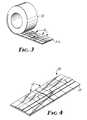
- Figure 3illustrates the results of a final die cutting operation where only the first, second, and third webs 30, 32, and 33 respectively, are die cut and the release liner web 31 is left intact.
- a plurality of adjacent electrodes 10are produced which are adhesively attached to a continuous release liner web 31 a.
- Thisprovides a plurality of electrodes which can be wound into a convoluted roll 50, to be used with dispensing apparatus similar to the conventional label dispensers, to dispense individual electrodes.
- This formatallows individual electrodes to be dispensed from a master roll only as they are needed by the consumer.
- FIG. 4A third alternative is illustrated in Figure 4 wherein is shown an electrode strip 28 comprising a predetermined number of electrodes 10 adhesively attached to a release liner strip 29.
- This configurationoccurs when the entire lamination including the release liner web 31 is cut at selected intervals corresponding to the length of the release liner strip 29, while between these selected intervals only the first, second, and third webs, 30, 32, and 33 respectively, are die cut separating the electrodes 10 but leaving the release liner web 31 intact.
- this embodimenthas ten electrodes adhesively attached to a release liner strip 29. This number of electrodes is convenient because it corresponds to the number of electrodes typically required for an electrocardiogram.
- the third web 33is laminated after the first and second webs, 30 and 32 respectively have . been die cut.
- the third web 33is then left intact over the entire strip of electrodes. Since in this embodiment all the electrodes on the strip will be used at the same time, the third web 33 can be removed by the user prior to applying the various electrodes.
Landscapes
- Life Sciences & Earth Sciences (AREA)
- Health & Medical Sciences (AREA)
- Medical Informatics (AREA)
- Biophysics (AREA)
- Pathology (AREA)
- Engineering & Computer Science (AREA)
- Biomedical Technology (AREA)
- Heart & Thoracic Surgery (AREA)
- Physics & Mathematics (AREA)
- Molecular Biology (AREA)
- Surgery (AREA)
- Animal Behavior & Ethology (AREA)
- General Health & Medical Sciences (AREA)
- Public Health (AREA)
- Veterinary Medicine (AREA)
- Measurement And Recording Of Electrical Phenomena And Electrical Characteristics Of The Living Body (AREA)
- Electrotherapy Devices (AREA)
Description
- This invention relates to disposable medical electrodes, and a method for making the same, and more particularly to disposable electrocardiogram electrodes.
- The delivering or monitoring of electrical signals to or from the human body is widespread. Hence, many types of electrodes have been developed through which electrical contact with the human body can be made. These electrodes are either permanent (i.e. reusable) electrodes, or disposable electrodes which are utilized only for a single patient and then discarded. The disposable electrodes have largely resulted from attempts to reduce the costs involved in the upkeep and cleaning of the permanent electrode between uses, as well as the patient and electrode preparation required prior to each use of the permanent electrodes. Such cost reduction attempts, however, have necessarily been tempered to ensure that the integrity and quality of the electrical contact established by the electrode was not sacrificed. Hence, most of the existing disposable medical electrodes retain metallic (silver/silver chloride) portions embedded within a packaged conductive gel to achieve integrity within the electrical contact (see e.g. U.S. Patent No. 3,868,946). These metallic components make up a large portion of the electrode's cost and thus substantially limit the amount by which the manufacturing cost can be reduced. The requirement of accurately placing the metallic component within the electrode also severely limits the efficient automation of the electrode manufacturing process.
- Another concern with the development of disposable electrodes was the potential that the conductive gel contained therein and used to increase the electrical contact between the electrode and the human body, might eventually desiccate, or might otherwise migrate to undesirable locations on the electrode, prior to the use of the electrode, thus conceivably degrading if not destroying the electrode's efficacy. To prevent either of these occurrences the existing electrodes generally incorporated an integral and centralized cup-like cavity in which the conductive gel was restrained and sealed (see e.g. U.S. Patent No. 4,126,126), and which had an adhesive coated flange-like projection extending outward from the side of the cavity to attach the electrode to the human body. To facilitate the manufacture of this central cavity and projecting flange, the existing electrodes typically had the configuration of a disk with all of the electrode's components centrally mounted thereon. This configuration, although allowing a partially automated manufacturing process, still required substantial manual interface to critically align the various components forming the electrode.
- It is known from document WO 81 01646 to manufacture medical electrodes continuously from a web of foam plastics material. The process described in this document starts with a foam plastics web laminated to a backing layer. Spaced apertures are then cut along the length of the web. A disc-shaped contact is stuck to the web on the side opposite the backing layer. The apertures are then filled with conductive jelly held in a porous matrix. The top of the apertures are then sealed by removing the backing layer and replacing it with a backing layer without apertures. Finally, using an annular punch the individual finished electrodes are stamped out of the web. It is apparent from the process of this document that the alignment of tools from one step to the next is critical. Also there is a considerable amount of waste produced. These factors add to the cost of the final product.
- According to the present invention, however, there is provided a method of manufacturing disposable medical electrodes as defined in claim 1 comprising the steps of: cutting a plurality of openings along a first web of an adhesive coated material, with at least one opening at each of a plurality of predetermined locations which are longitudinally spaced from each other, laminating a release linear web to the adhesive coated surface of the first web, thereby defining a reservoir bordered by the release liner and the periphery of the opening, introducing a conductive gel into the reservoir, cutting a plurality of holes along a second web with at least one hole at each of a plurality of predetermined locations which are spaced longitudinally from each other, laminating the second web to the surface of the first web opposite the surface laminated to the release liner, with the holes in the second web generally centrally positioned over the openings in the first web, and with the second web covering and extending beyond each of the openings, laminating a third web to the surface of the second web opposite the surface laminated to the first web, with the third web covering and extending beyond each of the holes in the second web, and cutting the laminate formed by the above steps, at predetermined locations spaced longitudinally along the laminate, thereby separating the laminate into a plurality of electrodes. The release liner web may be laminated to the adhesive coated surface of the first web prior to cutting of the plurality of opening along the first web as defined in claim 6. When the electrodes have been formed they may be separated into individual electrodes by cutting across the web through all layers. Alternatively all layers except the release liner may be cut so that the electrodes remain on the web and yet may be removed individually when used. Another possibility envisaged by the invention is to cut the electrodes into strips of 10 or some other convenient number. This is done by cutting through all layers except the release liner to separate the individual electrodes and to sever the release liner in addition to define the strip. The invention also includes the electrodes themselves as defined in claim 6, and electrode strips as defined in claim 9.
- Since the configuration of the electrodes according to the present invention facilitates their direct manufacture from a plurality of laminated and continuous webs, greater control can be achieved over the placement of each of the components forming the electrodes. This control makes it possible to accurately position the various components at higher manufacturing speeds and with a substantially reduced labor requirement. The resulting rectangular configuration also lends itself to narrower electrodes having at least one straight edge, which facilitate the placement of the finished electrode upon the patient.
- The present invention will be further described hereinafter with reference to the accompanying drawing wherein:
- Figure 1 is a perspective view of a single electrode according to the present invention,
- Figure 2 is a schematic representation of a method of manufacturing medical electrodes according to the present invention;
- Figure 3 is a perspective view of a plurality of electrodes on a roll of release liner according to the present invention; and
- Figure 4 is a perspective view of a plurality of electrodes on a strip of release liner according to the present invention.
- A
disposable electrode 10 according to the present invention is best illustrated in Figure 1. Thiselectrode 10 has been die cut from a plurality of laminatedelongate webs electrodes 10 manufactured. Each of theelectrodes 10 comprises afirst sheet 12, typically a flexible foam material having one surface which is coated with a suitable adhesive. The flexibility of this foam permits its conformance to the varied configuration of the human body. Thefirst sheet 12 has arectangular opening 14 which has been die cut therethrough and which is spaced from each of the edges forming the outer boundaries of the first sheet. Other shaped openings are, of course, also viable. Aremovable release liner 16, typically a silicone coated paper, is laminated to thefirst sheet 12. This lamination can occur after theopening 14 has been cut, or alternatively prior to die cutting the opening providing adequate control can be achieved over the depth of the die cutting operation to ensure that therelease liner 16 is left intact sealing one end of theopening 14. Areservoir 17 is thus created within theelectrode 10, bordered by therelease liner 16 and the periphery of theopening 14. An electrically conductive gel is dispensed or introduced into thisreservoir 17 and the portion of the opening 14 remaining uncovered is sealed to retain the gel within thereservoir 17 and to prevent the gel from desiccating. The sealing of theopening 14 is done with a relatively stiff but yet resilientsecond sheet 20, such as a sheet of polyester film, commercially available from Eastman Kodak of New York, which is laminated over the opening 14 to the surface of thefirst sheet 12 opposite therelease liner 16. Thesecond sheet 20 of the preferred embodiment is also adhesive coated facilitating its attachment to thefirst sheet 12. Thesecond sheet 20 is slightly wider than theopening 14 and therefore will extend beyond the boundaries of theopening 14 permitting the adhesive on thesecond sheet 20 to affix thesecond sheet 20 to thefirst sheet 12, and thereby seal thereservoir 17. Thesecond sheet 20 has ahole 22 die cut therethrough which is disposed within thesecond sheet 20 so that it will be essentially centrally positioned over theopening 14 when thesecond sheet 20 is laminated to thefirst sheet 12. Thishole 22 is adapted to receive a connectinglead 24 from certain electrical equipment (not shown) to which theelectrode 10 is to be connected. In order to secure thelead 24 within thereservoir 17, thehole 22 is slightly smaller than the portion of thelead 24 which must be received, thus thesecond sheet 20 must be adequately resilient to permit the entrance and retention of thelead 24. Thesecond sheet 20 must also be relatively stiff to provide a supported surface on the foam through which thelead 24 can be inserted. Athird sheet 26 typically a flexible vinyl material is affixed over thehole 22, to the surface of thesecond sheet 20 opposite thefirst sheet 12. This third sheet is adhesively coated on one surface and has a width slightly greater than thehole 22 so that it extends beyond the boundaries of thehole 22 and may therefore be affixed to thesecond sheet 20, sealing thehole 22. Thisthird sheet 26 can be designed to be removable prior to the insertion of thelead 24 or it can be designed to be punctured by thelead 24 when thelead 24 is inserted in thehole 22. It is important to note that due to the manufacturing method for theseelectrodes 10, the first, second, and third sheets (12, 20 and 26 respectively) forming theelectrode 10 have at least two edges in common. This limitation exists because the sheets forming the individual electrodes are simultaneously die cut from elongate webs (30, 31, 32, and 33) which have been laminated together during the manufacture of the electrode. This final die cutting operation, separating the lamination into individual electrodes, cuts the webs along two or more defined lines which become the common edges of the various sheets forming the electrode. This final die cutting operation also creates the overall configuration of the electrode which in the case of the preferred embodiment is rectangular although other configurations are possible. The advantages of this structural limitation, i.e. that the sheets have two or more common edges, will become more apparent through the discussion of a method according to the present invention by which theelectrodes 10 are manufactured. - Figure 2 illustrates in schematic form the preferred embodiment of the method according to the present invention, for manufacturing the
medical electrodes 10. This method comprises a first die cutting operation in which a conventional die-cutting press and associated dies 40 cut a plurality ofopenings 14 at predetermined locations spaced longitudinally along afirstweb 30, i.e. the adhesive coated foam material. Arelease liner web 31 is then laminated to thefirst web 30 by conventional lamination means. This lamination defines thereservoir 17 into which the conductive gel is introduced. Depending upon the exact physical properties of the conductive gel, aroll coater 47, or some other technique of introducing this gel is utilized. Asecond web 32 is then laminated by conventional lamination means 43 to the surface of thefirst web 30 opposite therelease liner 31. A plurality ofholes 22 with a longitudinal spacing facilitating the alignment of theholes 22 over theopenings 14 in thefirst web 31, are cut by a conventional press and associated dies 42 into thesecond web 32 prior to this lamination. Theholes 22 are then covered by the lamination of athird web 33 to thesecond web 32. This is also done by conventional laminating means 45. It is extremely important to note that at this stage of the manufacturing method, all components making up the lamination are in web form. Since both ends of each of the webs are controlled, the various components can be oriented with respect to each other with an accuracy and at a speed not otherwise possible when the electrode consists of individual components which are individually assembled. This retention of control over the individual components making up theelectrode 10 contributes to a reduction in the manufacturing cost of theelectrode 10. Thus, only after all of the components have been aligned with respect to each other and laminated together, are the individual electrodes die cut from that lamination. This final die cutting operation utilizes a conventional press and associated dies 46 which are similar to those used in the previous die cutting operations. It is possible, however, by controlling the depth within the lamination in which this final die cutting occurs, to selectively leave therelease linerweb 31 intact (i.e. cutting only the first, 30, second, 32, and third 33 webs with the dies 46). This affords a number of alternative embodiments for theelectrode 10. For instance, Figure 1 illustrates the results of a final die cutting operation the entire lamination including therelease liner web 31 is cut during each and every cycle, i.e. this method producesindividual electrodes 10 which are not connected to each other. As an alternative to this, Figure 3 illustrates the results of a final die cutting operation where only the first, second, andthird webs release liner web 31 is left intact. In this case, a plurality ofadjacent electrodes 10 are produced which are adhesively attached to a continuousrelease liner web 31 a. This provides a plurality of electrodes which can be wound into aconvoluted roll 50, to be used with dispensing apparatus similar to the conventional label dispensers, to dispense individual electrodes. This format allows individual electrodes to be dispensed from a master roll only as they are needed by the consumer. A third alternative is illustrated in Figure 4 wherein is shown anelectrode strip 28 comprising a predetermined number ofelectrodes 10 adhesively attached to arelease liner strip 29. This configuration occurs when the entire lamination including therelease liner web 31 is cut at selected intervals corresponding to the length of therelease liner strip 29, while between these selected intervals only the first, second, and third webs, 30, 32, and 33 respectively, are die cut separating theelectrodes 10 but leaving therelease liner web 31 intact. Typically, this embodiment has ten electrodes adhesively attached to arelease liner strip 29. This number of electrodes is convenient because it corresponds to the number of electrodes typically required for an electrocardiogram. As a variation of this embodiment, it is also possible to laminate thethird web 33 after the first and second webs, 30 and 32 respectively have . been die cut. Thethird web 33 is then left intact over the entire strip of electrodes. Since in this embodiment all the electrodes on the strip will be used at the same time, thethird web 33 can be removed by the user prior to applying the various electrodes. - Having thus described some preferred embodiments of the present invention it must be understood that changes may be made in the size, shape, or configurations of some of the elements described herein without departing from the present invention as recited in the appended claims.
Claims (9)
Applications Claiming Priority (2)
| Application Number | Priority Date | Filing Date | Title |
|---|---|---|---|
| US06/285,254US4409981A (en) | 1981-07-20 | 1981-07-20 | Medical electrode |
| US285254 | 1988-12-16 |
Publications (3)
| Publication Number | Publication Date |
|---|---|
| EP0070626A2 EP0070626A2 (en) | 1983-01-26 |
| EP0070626A3 EP0070626A3 (en) | 1984-10-24 |
| EP0070626B1true EP0070626B1 (en) | 1987-09-30 |
Family
ID=23093450
Family Applications (1)
| Application Number | Title | Priority Date | Filing Date |
|---|---|---|---|
| EP82303258AExpiredEP0070626B1 (en) | 1981-07-20 | 1982-06-22 | Medical electrode |
Country Status (6)
| Country | Link |
|---|---|
| US (1) | US4409981A (en) |
| EP (1) | EP0070626B1 (en) |
| JP (1) | JPS5825143A (en) |
| AU (1) | AU553570B2 (en) |
| CA (1) | CA1183905A (en) |
| DE (1) | DE3277399D1 (en) |
Families Citing this family (111)
| Publication number | Priority date | Publication date | Assignee | Title |
|---|---|---|---|---|
| US4838273A (en)* | 1979-04-30 | 1989-06-13 | Baxter International Inc. | Medical electrode |
| US4580339A (en)* | 1982-08-05 | 1986-04-08 | Empi, Inc. | Method for fabricating a disposable electrode for transcutaneous nerve stimulator |
| US4856188A (en)* | 1984-10-12 | 1989-08-15 | Drug Delivery Systems Inc. | Method for making disposable and/or replenishable transdermal drug applicators |
| US4640289A (en)* | 1983-11-14 | 1987-02-03 | Minnesota Mining And Manufacturing Company | Biomedical electrode |
| US4727881A (en)* | 1983-11-14 | 1988-03-01 | Minnesota Mining And Manufacturing Company | Biomedical electrode |
| US4798642A (en)* | 1983-11-14 | 1989-01-17 | Minnesota Mining And Manufacturing Company | Method of making a biomedical electrode |
| GB2159717B (en)* | 1984-06-08 | 1988-05-18 | Sciotronic Ltd | Medical electrode |
| US4679564A (en)* | 1984-10-04 | 1987-07-14 | Sessions Robert W | Monitoring electrode attachable to a patient |
| US4832036A (en)* | 1985-05-13 | 1989-05-23 | Baxter International Inc. | Medical electrode |
| US4699679A (en)* | 1985-07-18 | 1987-10-13 | American Hospital Supply Corporation | Method of manufacturing medical electrode pads |
| US4635642A (en)* | 1985-07-18 | 1987-01-13 | American Hospital Supply Corporation | Medical electrode with reusable conductor |
| US4827939A (en)* | 1985-07-18 | 1989-05-09 | Baxter International Inc. | Medical electrode with reusable conductor and method of manufacture |
| US4653501A (en)* | 1986-04-17 | 1987-03-31 | Baxter Travenol Laboratories, Inc. | Medical electrode with reusable conductor |
| US4715382A (en)* | 1986-08-01 | 1987-12-29 | Minnesota Mining And Manufacturing Company | Flat biomedical electrode with reuseable lead wire |
| US4727880A (en)* | 1986-08-01 | 1988-03-01 | Minnesota Mining And Manufacturing Company | Flat, conformable, biomedical electrode |
| US4771783A (en)* | 1986-08-01 | 1988-09-20 | Minnesota Mining And Manufacturing Company | Flat, conformable, biomedical electrode |
| US4945911A (en)* | 1988-01-22 | 1990-08-07 | Joel Cohen | Medical electrode |
| AU104617S (en) | 1988-09-05 | 1989-08-15 | Fukuda Denshi Kk | Electrode pad |
| US5012810A (en)* | 1988-09-22 | 1991-05-07 | Minnesota Mining And Manufacturing Company | Biomedical electrode construction |
| US5078139A (en)* | 1988-09-22 | 1992-01-07 | Minnesota Mining And Manufacturing Company | Biomedical electrode construction |
| US5042144A (en)* | 1989-09-22 | 1991-08-27 | Health Concepts, Inc. | Method of formation of bio-electrode lamina |
| US5226225A (en)* | 1991-04-16 | 1993-07-13 | Minnesota Mining And Manufacturing Company | Method of making a biomedical electrode |
| US5813981A (en)* | 1995-12-29 | 1998-09-29 | Minnesota Mining And Manufacturing Company | Tab style electrode |
| US6135953A (en)* | 1996-01-25 | 2000-10-24 | 3M Innovative Properties Company | Multi-functional biomedical electrodes |
| US5713128A (en)* | 1996-02-16 | 1998-02-03 | Valleylab Inc | Electrosurgical pad apparatus and method of manufacture |
| US5921925A (en)* | 1997-05-30 | 1999-07-13 | Ndm, Inc. | Biomedical electrode having a disposable electrode and a reusable leadwire adapter that interfaces with a standard leadwire connector |
| GB9919682D0 (en)* | 1999-08-19 | 1999-10-20 | Dezac Limited | Improvements relating to muscle toner pads |
| US11229472B2 (en) | 2001-06-12 | 2022-01-25 | Cilag Gmbh International | Modular battery powered handheld surgical instrument with multiple magnetic position sensors |
| NZ534149A (en)* | 2001-12-19 | 2005-12-23 | Alza Corp | Reservoir housing having a conductive region integrally formed therein |
| US8525402B2 (en) | 2006-09-11 | 2013-09-03 | 3M Innovative Properties Company | Illumination devices and methods for making the same |
| US8581393B2 (en)* | 2006-09-21 | 2013-11-12 | 3M Innovative Properties Company | Thermally conductive LED assembly |
| US9089360B2 (en) | 2008-08-06 | 2015-07-28 | Ethicon Endo-Surgery, Inc. | Devices and techniques for cutting and coagulating tissue |
| US8663220B2 (en) | 2009-07-15 | 2014-03-04 | Ethicon Endo-Surgery, Inc. | Ultrasonic surgical instruments |
| US10441345B2 (en) | 2009-10-09 | 2019-10-15 | Ethicon Llc | Surgical generator for ultrasonic and electrosurgical devices |
| US11090104B2 (en) | 2009-10-09 | 2021-08-17 | Cilag Gmbh International | Surgical generator for ultrasonic and electrosurgical devices |
| US8469981B2 (en) | 2010-02-11 | 2013-06-25 | Ethicon Endo-Surgery, Inc. | Rotatable cutting implement arrangements for ultrasonic surgical instruments |
| WO2013119545A1 (en) | 2012-02-10 | 2013-08-15 | Ethicon-Endo Surgery, Inc. | Robotically controlled surgical instrument |
| US9439668B2 (en) | 2012-04-09 | 2016-09-13 | Ethicon Endo-Surgery, Llc | Switch arrangements for ultrasonic surgical instruments |
| US20140005705A1 (en) | 2012-06-29 | 2014-01-02 | Ethicon Endo-Surgery, Inc. | Surgical instruments with articulating shafts |
| US9393037B2 (en) | 2012-06-29 | 2016-07-19 | Ethicon Endo-Surgery, Llc | Surgical instruments with articulating shafts |
| US9408622B2 (en) | 2012-06-29 | 2016-08-09 | Ethicon Endo-Surgery, Llc | Surgical instruments with articulating shafts |
| US20140005702A1 (en) | 2012-06-29 | 2014-01-02 | Ethicon Endo-Surgery, Inc. | Ultrasonic surgical instruments with distally positioned transducers |
| US9198714B2 (en) | 2012-06-29 | 2015-12-01 | Ethicon Endo-Surgery, Inc. | Haptic feedback devices for surgical robot |
| US9226767B2 (en) | 2012-06-29 | 2016-01-05 | Ethicon Endo-Surgery, Inc. | Closed feedback control for electrosurgical device |
| US9326788B2 (en) | 2012-06-29 | 2016-05-03 | Ethicon Endo-Surgery, Llc | Lockout mechanism for use with robotic electrosurgical device |
| US9351754B2 (en) | 2012-06-29 | 2016-05-31 | Ethicon Endo-Surgery, Llc | Ultrasonic surgical instruments with distally positioned jaw assemblies |
| US9095367B2 (en) | 2012-10-22 | 2015-08-04 | Ethicon Endo-Surgery, Inc. | Flexible harmonic waveguides/blades for surgical instruments |
| US20140135804A1 (en) | 2012-11-15 | 2014-05-15 | Ethicon Endo-Surgery, Inc. | Ultrasonic and electrosurgical devices |
| US9814514B2 (en) | 2013-09-13 | 2017-11-14 | Ethicon Llc | Electrosurgical (RF) medical instruments for cutting and coagulating tissue |
| US9265926B2 (en) | 2013-11-08 | 2016-02-23 | Ethicon Endo-Surgery, Llc | Electrosurgical devices |
| GB2521228A (en) | 2013-12-16 | 2015-06-17 | Ethicon Endo Surgery Inc | Medical device |
| US9795436B2 (en) | 2014-01-07 | 2017-10-24 | Ethicon Llc | Harvesting energy from a surgical generator |
| US9554854B2 (en) | 2014-03-18 | 2017-01-31 | Ethicon Endo-Surgery, Llc | Detecting short circuits in electrosurgical medical devices |
| US10092310B2 (en) | 2014-03-27 | 2018-10-09 | Ethicon Llc | Electrosurgical devices |
| US9737355B2 (en) | 2014-03-31 | 2017-08-22 | Ethicon Llc | Controlling impedance rise in electrosurgical medical devices |
| US9913680B2 (en) | 2014-04-15 | 2018-03-13 | Ethicon Llc | Software algorithms for electrosurgical instruments |
| US10285724B2 (en) | 2014-07-31 | 2019-05-14 | Ethicon Llc | Actuation mechanisms and load adjustment assemblies for surgical instruments |
| US10639092B2 (en) | 2014-12-08 | 2020-05-05 | Ethicon Llc | Electrode configurations for surgical instruments |
| US10245095B2 (en) | 2015-02-06 | 2019-04-02 | Ethicon Llc | Electrosurgical instrument with rotation and articulation mechanisms |
| US10595929B2 (en) | 2015-03-24 | 2020-03-24 | Ethicon Llc | Surgical instruments with firing system overload protection mechanisms |
| US11129669B2 (en) | 2015-06-30 | 2021-09-28 | Cilag Gmbh International | Surgical system with user adaptable techniques based on tissue type |
| US10034704B2 (en) | 2015-06-30 | 2018-07-31 | Ethicon Llc | Surgical instrument with user adaptable algorithms |
| US11051873B2 (en) | 2015-06-30 | 2021-07-06 | Cilag Gmbh International | Surgical system with user adaptable techniques employing multiple energy modalities based on tissue parameters |
| US10898256B2 (en) | 2015-06-30 | 2021-01-26 | Ethicon Llc | Surgical system with user adaptable techniques based on tissue impedance |
| US11141213B2 (en) | 2015-06-30 | 2021-10-12 | Cilag Gmbh International | Surgical instrument with user adaptable techniques |
| US10194973B2 (en) | 2015-09-30 | 2019-02-05 | Ethicon Llc | Generator for digitally generating electrical signal waveforms for electrosurgical and ultrasonic surgical instruments |
| US10595930B2 (en) | 2015-10-16 | 2020-03-24 | Ethicon Llc | Electrode wiping surgical device |
| US10575892B2 (en) | 2015-12-31 | 2020-03-03 | Ethicon Llc | Adapter for electrical surgical instruments |
| US10716615B2 (en) | 2016-01-15 | 2020-07-21 | Ethicon Llc | Modular battery powered handheld surgical instrument with curved end effectors having asymmetric engagement between jaw and blade |
| US11051840B2 (en) | 2016-01-15 | 2021-07-06 | Ethicon Llc | Modular battery powered handheld surgical instrument with reusable asymmetric handle housing |
| US12193698B2 (en) | 2016-01-15 | 2025-01-14 | Cilag Gmbh International | Method for self-diagnosing operation of a control switch in a surgical instrument system |
| US11129670B2 (en) | 2016-01-15 | 2021-09-28 | Cilag Gmbh International | Modular battery powered handheld surgical instrument with selective application of energy based on button displacement, intensity, or local tissue characterization |
| US11229471B2 (en) | 2016-01-15 | 2022-01-25 | Cilag Gmbh International | Modular battery powered handheld surgical instrument with selective application of energy based on tissue characterization |
| US10555769B2 (en) | 2016-02-22 | 2020-02-11 | Ethicon Llc | Flexible circuits for electrosurgical instrument |
| US10646269B2 (en) | 2016-04-29 | 2020-05-12 | Ethicon Llc | Non-linear jaw gap for electrosurgical instruments |
| US10702329B2 (en) | 2016-04-29 | 2020-07-07 | Ethicon Llc | Jaw structure with distal post for electrosurgical instruments |
| US10485607B2 (en) | 2016-04-29 | 2019-11-26 | Ethicon Llc | Jaw structure with distal closure for electrosurgical instruments |
| US10456193B2 (en) | 2016-05-03 | 2019-10-29 | Ethicon Llc | Medical device with a bilateral jaw configuration for nerve stimulation |
| USD829917S1 (en) | 2016-08-04 | 2018-10-02 | Medline Industries, Inc. | Set of electrodes on a perforated backing sheet |
| US10376305B2 (en) | 2016-08-05 | 2019-08-13 | Ethicon Llc | Methods and systems for advanced harmonic energy |
| US11266430B2 (en) | 2016-11-29 | 2022-03-08 | Cilag Gmbh International | End effector control and calibration |
| US10695552B2 (en)* | 2016-12-01 | 2020-06-30 | Feng Ching Tu | Wiring loop structure of skin electrode pad production machine |
| US12012270B2 (en)* | 2018-12-20 | 2024-06-18 | Conmed Corporation | Medical electrode tear strip |
| CN110522445A (en)* | 2019-09-29 | 2019-12-03 | 联想(北京)有限公司 | Electrode slice and Medical Devices |
| US12082808B2 (en) | 2019-12-30 | 2024-09-10 | Cilag Gmbh International | Surgical instrument comprising a control system responsive to software configurations |
| US11660089B2 (en) | 2019-12-30 | 2023-05-30 | Cilag Gmbh International | Surgical instrument comprising a sensing system |
| US12076006B2 (en) | 2019-12-30 | 2024-09-03 | Cilag Gmbh International | Surgical instrument comprising an orientation detection system |
| US11911063B2 (en) | 2019-12-30 | 2024-02-27 | Cilag Gmbh International | Techniques for detecting ultrasonic blade to electrode contact and reducing power to ultrasonic blade |
| US11786291B2 (en) | 2019-12-30 | 2023-10-17 | Cilag Gmbh International | Deflectable support of RF energy electrode with respect to opposing ultrasonic blade |
| US11684412B2 (en) | 2019-12-30 | 2023-06-27 | Cilag Gmbh International | Surgical instrument with rotatable and articulatable surgical end effector |
| US12023086B2 (en) | 2019-12-30 | 2024-07-02 | Cilag Gmbh International | Electrosurgical instrument for delivering blended energy modalities to tissue |
| US11937866B2 (en) | 2019-12-30 | 2024-03-26 | Cilag Gmbh International | Method for an electrosurgical procedure |
| US12114912B2 (en) | 2019-12-30 | 2024-10-15 | Cilag Gmbh International | Non-biased deflectable electrode to minimize contact between ultrasonic blade and electrode |
| US11452525B2 (en) | 2019-12-30 | 2022-09-27 | Cilag Gmbh International | Surgical instrument comprising an adjustment system |
| US12343063B2 (en) | 2019-12-30 | 2025-07-01 | Cilag Gmbh International | Multi-layer clamp arm pad for enhanced versatility and performance of a surgical device |
| US11779329B2 (en) | 2019-12-30 | 2023-10-10 | Cilag Gmbh International | Surgical instrument comprising a flex circuit including a sensor system |
| US12064109B2 (en) | 2019-12-30 | 2024-08-20 | Cilag Gmbh International | Surgical instrument comprising a feedback control circuit |
| US20210196357A1 (en) | 2019-12-30 | 2021-07-01 | Ethicon Llc | Electrosurgical instrument with asynchronous energizing electrodes |
| US11779387B2 (en) | 2019-12-30 | 2023-10-10 | Cilag Gmbh International | Clamp arm jaw to minimize tissue sticking and improve tissue control |
| US11696776B2 (en) | 2019-12-30 | 2023-07-11 | Cilag Gmbh International | Articulatable surgical instrument |
| US20210196362A1 (en) | 2019-12-30 | 2021-07-01 | Ethicon Llc | Electrosurgical end effectors with thermally insulative and thermally conductive portions |
| US12262937B2 (en) | 2019-12-30 | 2025-04-01 | Cilag Gmbh International | User interface for surgical instrument with combination energy modality end-effector |
| US11937863B2 (en) | 2019-12-30 | 2024-03-26 | Cilag Gmbh International | Deflectable electrode with variable compression bias along the length of the deflectable electrode |
| US12053224B2 (en) | 2019-12-30 | 2024-08-06 | Cilag Gmbh International | Variation in electrode parameters and deflectable electrode to modify energy density and tissue interaction |
| US11986201B2 (en) | 2019-12-30 | 2024-05-21 | Cilag Gmbh International | Method for operating a surgical instrument |
| US11812957B2 (en) | 2019-12-30 | 2023-11-14 | Cilag Gmbh International | Surgical instrument comprising a signal interference resolution system |
| US12336747B2 (en) | 2019-12-30 | 2025-06-24 | Cilag Gmbh International | Method of operating a combination ultrasonic / bipolar RF surgical device with a combination energy modality end-effector |
| US11786294B2 (en) | 2019-12-30 | 2023-10-17 | Cilag Gmbh International | Control program for modular combination energy device |
| US11950797B2 (en) | 2019-12-30 | 2024-04-09 | Cilag Gmbh International | Deflectable electrode with higher distal bias relative to proximal bias |
| US11944366B2 (en) | 2019-12-30 | 2024-04-02 | Cilag Gmbh International | Asymmetric segmented ultrasonic support pad for cooperative engagement with a movable RF electrode |
| CN113951889B (en)* | 2021-09-24 | 2024-07-09 | 日月光半导体制造股份有限公司 | Biological signal acquisition device and monitoring equipment |
Family Cites Families (17)
| Publication number | Priority date | Publication date | Assignee | Title |
|---|---|---|---|---|
| US2943628A (en)* | 1957-02-27 | 1960-07-05 | William L Howell | Electrode assembly |
| FR1524246A (en)* | 1967-03-28 | 1968-05-10 | Thomson Medical | Improvements to electrical contact devices |
| US3518984A (en)* | 1967-10-12 | 1970-07-07 | Univ Johns Hopkins | Packaged diagnostic electrode device |
| US3805769A (en)* | 1971-08-27 | 1974-04-23 | R Sessions | Disposable electrode |
| US3774592A (en)* | 1971-12-16 | 1973-11-27 | Xerox Corp | Method for providing an improved body electrode electrical connection |
| US3868946A (en)* | 1973-07-13 | 1975-03-04 | James S Hurley | Medical electrode |
| US3862633A (en)* | 1974-05-06 | 1975-01-28 | Kenneth C Allison | Electrode |
| US4067322A (en)* | 1974-07-19 | 1978-01-10 | Johnson Joseph H | Disposable, pre-gel body electrodes |
| US4079731A (en)* | 1975-07-03 | 1978-03-21 | Cardiolink Electrodes, Ltd. | Medical electrodes |
| US4051842A (en)* | 1975-09-15 | 1977-10-04 | International Medical Corporation | Electrode and interfacing pad for electrical physiological systems |
| US4126126A (en)* | 1976-07-27 | 1978-11-21 | C. R. Bard, Inc. | Non-metallic pregelled electrode |
| US4102331A (en)* | 1976-09-21 | 1978-07-25 | Datascope Corporation | Device for transmitting electrical energy |
| JPS5421080A (en)* | 1977-07-18 | 1979-02-16 | Tokyo Shibaura Electric Co | Living body electrode |
| US4177817A (en)* | 1978-02-01 | 1979-12-11 | C. R. Bard, Inc. | Dual terminal transcutaneous electrode |
| DE2836904C2 (en)* | 1978-08-23 | 1980-07-03 | Siemens Ag, 1000 Berlin Und 8000 Muenchen | Adhesive mount |
| US4365634A (en)* | 1979-12-06 | 1982-12-28 | C. R. Bard, Inc. | Medical electrode construction |
| US4353372A (en)* | 1980-02-11 | 1982-10-12 | Bunker Ramo Corporation | Medical cable set and electrode therefor |
- 1981
- 1981-07-20USUS06/285,254patent/US4409981A/ennot_activeExpired - Lifetime
- 1982
- 1982-06-22DEDE8282303258Tpatent/DE3277399D1/ennot_activeExpired
- 1982-06-22EPEP82303258Apatent/EP0070626B1/ennot_activeExpired
- 1982-06-24CACA000405903Apatent/CA1183905A/ennot_activeExpired
- 1982-07-19JPJP57125613Apatent/JPS5825143A/enactivePending
- 1982-07-20AUAU86208/82Apatent/AU553570B2/ennot_activeCeased
Also Published As
| Publication number | Publication date |
|---|---|
| AU8620882A (en) | 1983-01-27 |
| EP0070626A3 (en) | 1984-10-24 |
| CA1183905A (en) | 1985-03-12 |
| EP0070626A2 (en) | 1983-01-26 |
| JPS5825143A (en) | 1983-02-15 |
| DE3277399D1 (en) | 1987-11-05 |
| AU553570B2 (en) | 1986-07-24 |
| US4409981A (en) | 1983-10-18 |
Similar Documents
| Publication | Publication Date | Title |
|---|---|---|
| EP0070626B1 (en) | Medical electrode | |
| EP0216455B1 (en) | Medical electrode with reusable conductor and method of manufacture | |
| US5792092A (en) | Sterile adhesive bandage and associated methods | |
| US4787380A (en) | Delivery system and package for a self adhering polymer medical dressing | |
| US4883457A (en) | Disposable and/or replenishable transdermal drug applicators and methods of manufacturing same | |
| EP0293893B1 (en) | A method of manufactoring a transdermal drug applicator | |
| US5981823A (en) | Sterile adhesive bandage and associated methods | |
| US4827939A (en) | Medical electrode with reusable conductor and method of manufacture | |
| CA1232806A (en) | Topical dressings | |
| US4699679A (en) | Method of manufacturing medical electrode pads | |
| US20030204158A1 (en) | Segmented product with dispensing tabs | |
| US6440513B1 (en) | Flat transdermal medicated self-adhesive patch | |
| US4327737A (en) | Medical electrode assembly | |
| DE3204582A1 (en) | Method of continuously producing plaster packs for transdermal administration of medicaments | |
| US6174402B1 (en) | Adhesive label, method and apparatus of manufacturing the same | |
| US4433481A (en) | Method of mounting medical electrode assembly | |
| JPS5991176A (en) | Manufacturing method for double-sided adhesive strip distribution tape | |
| JPH0430612Y2 (en) | ||
| DE3902011C2 (en) | Method of making a label | |
| WO1999024341A1 (en) | Dispenser for a sterile adhesive bandage | |
| JPS5991174A (en) | Manufacturing method for double-sided adhesive strip distribution tape | |
| JPH0716683Y2 (en) | Horizontal tear adhesive tape | |
| JPH0320137Y2 (en) | ||
| JPH1195670A (en) | Seal with release mount | |
| JPH0210429B2 (en) |
Legal Events
| Date | Code | Title | Description |
|---|---|---|---|
| PUAI | Public reference made under article 153(3) epc to a published international application that has entered the european phase | Free format text:ORIGINAL CODE: 0009012 | |
| AK | Designated contracting states | Designated state(s):DE FR GB IT SE | |
| PUAL | Search report despatched | Free format text:ORIGINAL CODE: 0009013 | |
| AK | Designated contracting states | Designated state(s):DE FR GB IT SE | |
| 17P | Request for examination filed | Effective date:19850102 | |
| 17Q | First examination report despatched | Effective date:19860723 | |
| GRAA | (expected) grant | Free format text:ORIGINAL CODE: 0009210 | |
| ITF | It: translation for a ep patent filed | ||
| AK | Designated contracting states | Kind code of ref document:B1 Designated state(s):DE FR GB IT SE | |
| REF | Corresponds to: | Ref document number:3277399 Country of ref document:DE Date of ref document:19871105 | |
| ET | Fr: translation filed | ||
| PLBE | No opposition filed within time limit | Free format text:ORIGINAL CODE: 0009261 | |
| STAA | Information on the status of an ep patent application or granted ep patent | Free format text:STATUS: NO OPPOSITION FILED WITHIN TIME LIMIT | |
| 26N | No opposition filed | ||
| PGFP | Annual fee paid to national office [announced via postgrant information from national office to epo] | Ref country code:DE Payment date:19890519 Year of fee payment:8 | |
| PGFP | Annual fee paid to national office [announced via postgrant information from national office to epo] | Ref country code:SE Payment date:19890522 Year of fee payment:8 Ref country code:FR Payment date:19890522 Year of fee payment:8 | |
| PGFP | Annual fee paid to national office [announced via postgrant information from national office to epo] | Ref country code:GB Payment date:19890531 Year of fee payment:8 | |
| REG | Reference to a national code | Ref country code:GB Ref legal event code:732 | |
| ITTA | It: last paid annual fee | ||
| PG25 | Lapsed in a contracting state [announced via postgrant information from national office to epo] | Ref country code:GB Effective date:19900622 | |
| PG25 | Lapsed in a contracting state [announced via postgrant information from national office to epo] | Ref country code:SE Effective date:19900623 | |
| GBPC | Gb: european patent ceased through non-payment of renewal fee | ||
| PG25 | Lapsed in a contracting state [announced via postgrant information from national office to epo] | Ref country code:FR Effective date:19910228 | |
| PG25 | Lapsed in a contracting state [announced via postgrant information from national office to epo] | Ref country code:DE Effective date:19910301 | |
| REG | Reference to a national code | Ref country code:FR Ref legal event code:ST | |
| EUG | Se: european patent has lapsed | Ref document number:82303258.6 Effective date:19910206 |