EP0069717B1 - Method for utilizing boil-off gas from cryogenic liquids as fuel in a dual gas/oil-burning diesel engine, and a system for utilizing the method - Google Patents
Method for utilizing boil-off gas from cryogenic liquids as fuel in a dual gas/oil-burning diesel engine, and a system for utilizing the methodDownload PDFInfo
- Publication number
- EP0069717B1 EP0069717B1EP82850144AEP82850144AEP0069717B1EP 0069717 B1EP0069717 B1EP 0069717B1EP 82850144 AEP82850144 AEP 82850144AEP 82850144 AEP82850144 AEP 82850144AEP 0069717 B1EP0069717 B1EP 0069717B1
- Authority
- EP
- European Patent Office
- Prior art keywords
- gas
- fuel
- boil
- oil
- compressor
- Prior art date
- Legal status (The legal status is an assumption and is not a legal conclusion. Google has not performed a legal analysis and makes no representation as to the accuracy of the status listed.)
- Expired
Links
Images


Classifications
- B—PERFORMING OPERATIONS; TRANSPORTING
- B63—SHIPS OR OTHER WATERBORNE VESSELS; RELATED EQUIPMENT
- B63J—AUXILIARIES ON VESSELS
- B63J99/00—Subject matter not provided for in other groups of this subclass
- B—PERFORMING OPERATIONS; TRANSPORTING
- B63—SHIPS OR OTHER WATERBORNE VESSELS; RELATED EQUIPMENT
- B63B—SHIPS OR OTHER WATERBORNE VESSELS; EQUIPMENT FOR SHIPPING
- B63B25/00—Load-accommodating arrangements, e.g. stowing, trimming; Vessels characterised thereby
- B63B25/02—Load-accommodating arrangements, e.g. stowing, trimming; Vessels characterised thereby for bulk goods
- B63B25/08—Load-accommodating arrangements, e.g. stowing, trimming; Vessels characterised thereby for bulk goods fluid
- B63B25/12—Load-accommodating arrangements, e.g. stowing, trimming; Vessels characterised thereby for bulk goods fluid closed
- F—MECHANICAL ENGINEERING; LIGHTING; HEATING; WEAPONS; BLASTING
- F02—COMBUSTION ENGINES; HOT-GAS OR COMBUSTION-PRODUCT ENGINE PLANTS
- F02B—INTERNAL-COMBUSTION PISTON ENGINES; COMBUSTION ENGINES IN GENERAL
- F02B69/00—Internal-combustion engines convertible into other combustion-engine type, not provided for in F02B11/00; Internal-combustion engines of different types characterised by constructions facilitating use of same main engine-parts in different types
- F02B69/02—Internal-combustion engines convertible into other combustion-engine type, not provided for in F02B11/00; Internal-combustion engines of different types characterised by constructions facilitating use of same main engine-parts in different types for different fuel types, other than engines indifferent to fuel consumed, e.g. convertible from light to heavy fuel
- F02B69/04—Internal-combustion engines convertible into other combustion-engine type, not provided for in F02B11/00; Internal-combustion engines of different types characterised by constructions facilitating use of same main engine-parts in different types for different fuel types, other than engines indifferent to fuel consumed, e.g. convertible from light to heavy fuel for gaseous and non-gaseous fuels
- F—MECHANICAL ENGINEERING; LIGHTING; HEATING; WEAPONS; BLASTING
- F02—COMBUSTION ENGINES; HOT-GAS OR COMBUSTION-PRODUCT ENGINE PLANTS
- F02D—CONTROLLING COMBUSTION ENGINES
- F02D19/00—Controlling engines characterised by their use of non-liquid fuels, pluralities of fuels, or non-fuel substances added to the combustible mixtures
- F02D19/02—Controlling engines characterised by their use of non-liquid fuels, pluralities of fuels, or non-fuel substances added to the combustible mixtures peculiar to engines working with gaseous fuels
- F02D19/021—Control of components of the fuel supply system
- F02D19/022—Control of components of the fuel supply system to adjust the fuel pressure, temperature or composition
- F—MECHANICAL ENGINEERING; LIGHTING; HEATING; WEAPONS; BLASTING
- F02—COMBUSTION ENGINES; HOT-GAS OR COMBUSTION-PRODUCT ENGINE PLANTS
- F02D—CONTROLLING COMBUSTION ENGINES
- F02D19/00—Controlling engines characterised by their use of non-liquid fuels, pluralities of fuels, or non-fuel substances added to the combustible mixtures
- F02D19/06—Controlling engines characterised by their use of non-liquid fuels, pluralities of fuels, or non-fuel substances added to the combustible mixtures peculiar to engines working with pluralities of fuels, e.g. alternatively with light and heavy fuel oil, other than engines indifferent to the fuel consumed
- F02D19/0639—Controlling engines characterised by their use of non-liquid fuels, pluralities of fuels, or non-fuel substances added to the combustible mixtures peculiar to engines working with pluralities of fuels, e.g. alternatively with light and heavy fuel oil, other than engines indifferent to the fuel consumed characterised by the type of fuels
- F02D19/0642—Controlling engines characterised by their use of non-liquid fuels, pluralities of fuels, or non-fuel substances added to the combustible mixtures peculiar to engines working with pluralities of fuels, e.g. alternatively with light and heavy fuel oil, other than engines indifferent to the fuel consumed characterised by the type of fuels at least one fuel being gaseous, the other fuels being gaseous or liquid at standard conditions
- F02D19/0647—Controlling engines characterised by their use of non-liquid fuels, pluralities of fuels, or non-fuel substances added to the combustible mixtures peculiar to engines working with pluralities of fuels, e.g. alternatively with light and heavy fuel oil, other than engines indifferent to the fuel consumed characterised by the type of fuels at least one fuel being gaseous, the other fuels being gaseous or liquid at standard conditions the gaseous fuel being liquefied petroleum gas [LPG], liquefied natural gas [LNG], compressed natural gas [CNG] or dimethyl ether [DME]
- F—MECHANICAL ENGINEERING; LIGHTING; HEATING; WEAPONS; BLASTING
- F02—COMBUSTION ENGINES; HOT-GAS OR COMBUSTION-PRODUCT ENGINE PLANTS
- F02D—CONTROLLING COMBUSTION ENGINES
- F02D19/00—Controlling engines characterised by their use of non-liquid fuels, pluralities of fuels, or non-fuel substances added to the combustible mixtures
- F02D19/06—Controlling engines characterised by their use of non-liquid fuels, pluralities of fuels, or non-fuel substances added to the combustible mixtures peculiar to engines working with pluralities of fuels, e.g. alternatively with light and heavy fuel oil, other than engines indifferent to the fuel consumed
- F02D19/0663—Details on the fuel supply system, e.g. tanks, valves, pipes, pumps, rails, injectors or mixers
- F02D19/0686—Injectors
- F02D19/0689—Injectors for in-cylinder direct injection
- F—MECHANICAL ENGINEERING; LIGHTING; HEATING; WEAPONS; BLASTING
- F02—COMBUSTION ENGINES; HOT-GAS OR COMBUSTION-PRODUCT ENGINE PLANTS
- F02D—CONTROLLING COMBUSTION ENGINES
- F02D19/00—Controlling engines characterised by their use of non-liquid fuels, pluralities of fuels, or non-fuel substances added to the combustible mixtures
- F02D19/06—Controlling engines characterised by their use of non-liquid fuels, pluralities of fuels, or non-fuel substances added to the combustible mixtures peculiar to engines working with pluralities of fuels, e.g. alternatively with light and heavy fuel oil, other than engines indifferent to the fuel consumed
- F02D19/0663—Details on the fuel supply system, e.g. tanks, valves, pipes, pumps, rails, injectors or mixers
- F02D19/0686—Injectors
- F02D19/0692—Arrangement of multiple injectors per combustion chamber
- F—MECHANICAL ENGINEERING; LIGHTING; HEATING; WEAPONS; BLASTING
- F02—COMBUSTION ENGINES; HOT-GAS OR COMBUSTION-PRODUCT ENGINE PLANTS
- F02D—CONTROLLING COMBUSTION ENGINES
- F02D19/00—Controlling engines characterised by their use of non-liquid fuels, pluralities of fuels, or non-fuel substances added to the combustible mixtures
- F02D19/06—Controlling engines characterised by their use of non-liquid fuels, pluralities of fuels, or non-fuel substances added to the combustible mixtures peculiar to engines working with pluralities of fuels, e.g. alternatively with light and heavy fuel oil, other than engines indifferent to the fuel consumed
- F02D19/08—Controlling engines characterised by their use of non-liquid fuels, pluralities of fuels, or non-fuel substances added to the combustible mixtures peculiar to engines working with pluralities of fuels, e.g. alternatively with light and heavy fuel oil, other than engines indifferent to the fuel consumed simultaneously using pluralities of fuels
- F02D19/10—Controlling engines characterised by their use of non-liquid fuels, pluralities of fuels, or non-fuel substances added to the combustible mixtures peculiar to engines working with pluralities of fuels, e.g. alternatively with light and heavy fuel oil, other than engines indifferent to the fuel consumed simultaneously using pluralities of fuels peculiar to compression-ignition engines in which the main fuel is gaseous
- F—MECHANICAL ENGINEERING; LIGHTING; HEATING; WEAPONS; BLASTING
- F02—COMBUSTION ENGINES; HOT-GAS OR COMBUSTION-PRODUCT ENGINE PLANTS
- F02M—SUPPLYING COMBUSTION ENGINES IN GENERAL WITH COMBUSTIBLE MIXTURES OR CONSTITUENTS THEREOF
- F02M21/00—Apparatus for supplying engines with non-liquid fuels, e.g. gaseous fuels stored in liquid form
- F02M21/02—Apparatus for supplying engines with non-liquid fuels, e.g. gaseous fuels stored in liquid form for gaseous fuels
- F02M21/0218—Details on the gaseous fuel supply system, e.g. tanks, valves, pipes, pumps, rails, injectors or mixers
- F02M21/0221—Fuel storage reservoirs, e.g. cryogenic tanks
- F02M21/0224—Secondary gaseous fuel storages
- F—MECHANICAL ENGINEERING; LIGHTING; HEATING; WEAPONS; BLASTING
- F02—COMBUSTION ENGINES; HOT-GAS OR COMBUSTION-PRODUCT ENGINE PLANTS
- F02M—SUPPLYING COMBUSTION ENGINES IN GENERAL WITH COMBUSTIBLE MIXTURES OR CONSTITUENTS THEREOF
- F02M21/00—Apparatus for supplying engines with non-liquid fuels, e.g. gaseous fuels stored in liquid form
- F02M21/02—Apparatus for supplying engines with non-liquid fuels, e.g. gaseous fuels stored in liquid form for gaseous fuels
- F02M21/0218—Details on the gaseous fuel supply system, e.g. tanks, valves, pipes, pumps, rails, injectors or mixers
- F02M21/0245—High pressure fuel supply systems; Rails; Pumps; Arrangement of valves
- F—MECHANICAL ENGINEERING; LIGHTING; HEATING; WEAPONS; BLASTING
- F02—COMBUSTION ENGINES; HOT-GAS OR COMBUSTION-PRODUCT ENGINE PLANTS
- F02M—SUPPLYING COMBUSTION ENGINES IN GENERAL WITH COMBUSTIBLE MIXTURES OR CONSTITUENTS THEREOF
- F02M21/00—Apparatus for supplying engines with non-liquid fuels, e.g. gaseous fuels stored in liquid form
- F02M21/02—Apparatus for supplying engines with non-liquid fuels, e.g. gaseous fuels stored in liquid form for gaseous fuels
- F02M21/0218—Details on the gaseous fuel supply system, e.g. tanks, valves, pipes, pumps, rails, injectors or mixers
- F02M21/0287—Details on the gaseous fuel supply system, e.g. tanks, valves, pipes, pumps, rails, injectors or mixers characterised by the transition from liquid to gaseous phase ; Injection in liquid phase; Cooling and low temperature storage
- F—MECHANICAL ENGINEERING; LIGHTING; HEATING; WEAPONS; BLASTING
- F17—STORING OR DISTRIBUTING GASES OR LIQUIDS
- F17C—VESSELS FOR CONTAINING OR STORING COMPRESSED, LIQUEFIED OR SOLIDIFIED GASES; FIXED-CAPACITY GAS-HOLDERS; FILLING VESSELS WITH, OR DISCHARGING FROM VESSELS, COMPRESSED, LIQUEFIED, OR SOLIDIFIED GASES
- F17C9/00—Methods or apparatus for discharging liquefied or solidified gases from vessels not under pressure
- F17C9/02—Methods or apparatus for discharging liquefied or solidified gases from vessels not under pressure with change of state, e.g. vaporisation
- F17C9/04—Recovery of thermal energy
- B—PERFORMING OPERATIONS; TRANSPORTING
- B63—SHIPS OR OTHER WATERBORNE VESSELS; RELATED EQUIPMENT
- B63J—AUXILIARIES ON VESSELS
- B63J99/00—Subject matter not provided for in other groups of this subclass
- B63J2099/001—Burning of transported goods, e.g. fuel, boil-off or refuse
- B63J2099/003—Burning of transported goods, e.g. fuel, boil-off or refuse of cargo oil or fuel, or of boil-off gases, e.g. for propulsive purposes
- F—MECHANICAL ENGINEERING; LIGHTING; HEATING; WEAPONS; BLASTING
- F02—COMBUSTION ENGINES; HOT-GAS OR COMBUSTION-PRODUCT ENGINE PLANTS
- F02B—INTERNAL-COMBUSTION PISTON ENGINES; COMBUSTION ENGINES IN GENERAL
- F02B3/00—Engines characterised by air compression and subsequent fuel addition
- F02B3/06—Engines characterised by air compression and subsequent fuel addition with compression ignition
- F—MECHANICAL ENGINEERING; LIGHTING; HEATING; WEAPONS; BLASTING
- F17—STORING OR DISTRIBUTING GASES OR LIQUIDS
- F17C—VESSELS FOR CONTAINING OR STORING COMPRESSED, LIQUEFIED OR SOLIDIFIED GASES; FIXED-CAPACITY GAS-HOLDERS; FILLING VESSELS WITH, OR DISCHARGING FROM VESSELS, COMPRESSED, LIQUEFIED, OR SOLIDIFIED GASES
- F17C2201/00—Vessel construction, in particular geometry, arrangement or size
- F17C2201/01—Shape
- F17C2201/0128—Shape spherical or elliptical
- F—MECHANICAL ENGINEERING; LIGHTING; HEATING; WEAPONS; BLASTING
- F17—STORING OR DISTRIBUTING GASES OR LIQUIDS
- F17C—VESSELS FOR CONTAINING OR STORING COMPRESSED, LIQUEFIED OR SOLIDIFIED GASES; FIXED-CAPACITY GAS-HOLDERS; FILLING VESSELS WITH, OR DISCHARGING FROM VESSELS, COMPRESSED, LIQUEFIED, OR SOLIDIFIED GASES
- F17C2205/00—Vessel construction, in particular mounting arrangements, attachments or identifications means
- F17C2205/01—Mounting arrangements
- F17C2205/0123—Mounting arrangements characterised by number of vessels
- F17C2205/013—Two or more vessels
- F17C2205/0134—Two or more vessels characterised by the presence of fluid connection between vessels
- F—MECHANICAL ENGINEERING; LIGHTING; HEATING; WEAPONS; BLASTING
- F17—STORING OR DISTRIBUTING GASES OR LIQUIDS
- F17C—VESSELS FOR CONTAINING OR STORING COMPRESSED, LIQUEFIED OR SOLIDIFIED GASES; FIXED-CAPACITY GAS-HOLDERS; FILLING VESSELS WITH, OR DISCHARGING FROM VESSELS, COMPRESSED, LIQUEFIED, OR SOLIDIFIED GASES
- F17C2221/00—Handled fluid, in particular type of fluid
- F17C2221/03—Mixtures
- F17C2221/032—Hydrocarbons
- F17C2221/033—Methane, e.g. natural gas, CNG, LNG, GNL, GNC, PLNG
- F—MECHANICAL ENGINEERING; LIGHTING; HEATING; WEAPONS; BLASTING
- F17—STORING OR DISTRIBUTING GASES OR LIQUIDS
- F17C—VESSELS FOR CONTAINING OR STORING COMPRESSED, LIQUEFIED OR SOLIDIFIED GASES; FIXED-CAPACITY GAS-HOLDERS; FILLING VESSELS WITH, OR DISCHARGING FROM VESSELS, COMPRESSED, LIQUEFIED, OR SOLIDIFIED GASES
- F17C2223/00—Handled fluid before transfer, i.e. state of fluid when stored in the vessel or before transfer from the vessel
- F17C2223/01—Handled fluid before transfer, i.e. state of fluid when stored in the vessel or before transfer from the vessel characterised by the phase
- F17C2223/0146—Two-phase
- F17C2223/0153—Liquefied gas, e.g. LPG, GPL
- F17C2223/0161—Liquefied gas, e.g. LPG, GPL cryogenic, e.g. LNG, GNL, PLNG
- F—MECHANICAL ENGINEERING; LIGHTING; HEATING; WEAPONS; BLASTING
- F17—STORING OR DISTRIBUTING GASES OR LIQUIDS
- F17C—VESSELS FOR CONTAINING OR STORING COMPRESSED, LIQUEFIED OR SOLIDIFIED GASES; FIXED-CAPACITY GAS-HOLDERS; FILLING VESSELS WITH, OR DISCHARGING FROM VESSELS, COMPRESSED, LIQUEFIED, OR SOLIDIFIED GASES
- F17C2223/00—Handled fluid before transfer, i.e. state of fluid when stored in the vessel or before transfer from the vessel
- F17C2223/03—Handled fluid before transfer, i.e. state of fluid when stored in the vessel or before transfer from the vessel characterised by the pressure level
- F17C2223/033—Small pressure, e.g. for liquefied gas
- F—MECHANICAL ENGINEERING; LIGHTING; HEATING; WEAPONS; BLASTING
- F17—STORING OR DISTRIBUTING GASES OR LIQUIDS
- F17C—VESSELS FOR CONTAINING OR STORING COMPRESSED, LIQUEFIED OR SOLIDIFIED GASES; FIXED-CAPACITY GAS-HOLDERS; FILLING VESSELS WITH, OR DISCHARGING FROM VESSELS, COMPRESSED, LIQUEFIED, OR SOLIDIFIED GASES
- F17C2250/00—Accessories; Control means; Indicating, measuring or monitoring of parameters
- F17C2250/03—Control means
- F17C2250/032—Control means using computers
- F—MECHANICAL ENGINEERING; LIGHTING; HEATING; WEAPONS; BLASTING
- F17—STORING OR DISTRIBUTING GASES OR LIQUIDS
- F17C—VESSELS FOR CONTAINING OR STORING COMPRESSED, LIQUEFIED OR SOLIDIFIED GASES; FIXED-CAPACITY GAS-HOLDERS; FILLING VESSELS WITH, OR DISCHARGING FROM VESSELS, COMPRESSED, LIQUEFIED, OR SOLIDIFIED GASES
- F17C2265/00—Effects achieved by gas storage or gas handling
- F17C2265/03—Treating the boil-off
- F17C2265/032—Treating the boil-off by recovery
- F—MECHANICAL ENGINEERING; LIGHTING; HEATING; WEAPONS; BLASTING
- F17—STORING OR DISTRIBUTING GASES OR LIQUIDS
- F17C—VESSELS FOR CONTAINING OR STORING COMPRESSED, LIQUEFIED OR SOLIDIFIED GASES; FIXED-CAPACITY GAS-HOLDERS; FILLING VESSELS WITH, OR DISCHARGING FROM VESSELS, COMPRESSED, LIQUEFIED, OR SOLIDIFIED GASES
- F17C2265/00—Effects achieved by gas storage or gas handling
- F17C2265/06—Fluid distribution
- F17C2265/066—Fluid distribution for feeding engines for propulsion
- Y—GENERAL TAGGING OF NEW TECHNOLOGICAL DEVELOPMENTS; GENERAL TAGGING OF CROSS-SECTIONAL TECHNOLOGIES SPANNING OVER SEVERAL SECTIONS OF THE IPC; TECHNICAL SUBJECTS COVERED BY FORMER USPC CROSS-REFERENCE ART COLLECTIONS [XRACs] AND DIGESTS
- Y02—TECHNOLOGIES OR APPLICATIONS FOR MITIGATION OR ADAPTATION AGAINST CLIMATE CHANGE
- Y02T—CLIMATE CHANGE MITIGATION TECHNOLOGIES RELATED TO TRANSPORTATION
- Y02T10/00—Road transport of goods or passengers
- Y02T10/10—Internal combustion engine [ICE] based vehicles
- Y02T10/30—Use of alternative fuels, e.g. biofuels
- Y—GENERAL TAGGING OF NEW TECHNOLOGICAL DEVELOPMENTS; GENERAL TAGGING OF CROSS-SECTIONAL TECHNOLOGIES SPANNING OVER SEVERAL SECTIONS OF THE IPC; TECHNICAL SUBJECTS COVERED BY FORMER USPC CROSS-REFERENCE ART COLLECTIONS [XRACs] AND DIGESTS
- Y02—TECHNOLOGIES OR APPLICATIONS FOR MITIGATION OR ADAPTATION AGAINST CLIMATE CHANGE
- Y02T—CLIMATE CHANGE MITIGATION TECHNOLOGIES RELATED TO TRANSPORTATION
- Y02T70/00—Maritime or waterways transport
- Y02T70/50—Measures to reduce greenhouse gas emissions related to the propulsion system
Definitions
- the inventionrelates to a method for utilizing compressed boil-off gas from cryogenic liquids as fuel in a dual gas/oil-burning diesel engine on board an oceangoing vessel, and to a system for supplying boil-off gas from a cryogenic liquid as fuel to a dual gas/oil-burning diesel engine on board a ship.
- the inventionhas been especially developed in connection with so-called LNG carriers, i.e., ships which carry natural gas in liquefied form, hereafter termed cryogenic liquid.
- LNG carriersi.e., ships which carry natural gas in liquefied form
- cryogenic liquidgas carriers and especially LNG carriers have a special problem in that heat leaks to the cargo tanks cause the formation of so-called boil-off, i.e., a certain quantity of gas is produced which must be taken care off, either by recondensation or by combustion, or alternately by utilizing the gas as fuel for propulsion and auxiliary machinery.
- boil-offAs fuel on board LNG carriers, the solution most frequently utilized has been to combust the boil-off gas in connection with steam turbine machinery, i.e., as supplementary fuel for the ship boilers, which also burn heavy oil. Operating experience is good with such machinery, but the level of efficiency and bunker fuel consumption are not satisfactory.
- Pure gas-fueled enginesare available today for lower and average output power ranges, i.e., up to some thousand kW.
- a marine installationalso exists which has a slow-running, dual gas/oil-burning diesel engine with an output power of about 15,000 kW.
- the gasis introduced into the combustion chambers or cylinders at moderate pressure immediately after the compression stroke commences.
- the gas/air mixtureis ignited by spark plugs or "pilot" fuel, i.e., a small amount of diesel oil is injected at the moment when combustion is desired.
- spark plugs or "pilot" fueli.e., a small amount of diesel oil is injected at the moment when combustion is desired.
- Onethereby obtains an almost instantaneous combustion with an accompanying high rise in pressure (the Otto process). Consequently, the amount of gas must be restricted, which in turn results in a reduction of efficiency and a limited capability for combusting gas.
- the proportion of gasmust be held below about 55% of the total fuel requirement at full output power. This means that for larger vessels with large quantities of boil-off, no such suitable dual gas/oil-burning engines exist which can combust all the boil-off gas with sufficient margin and the desirable efficiency.
- boil-offcan be utilized in a dual gas/oil-burning diesel engine under these conditions provided that the boil-off gas is supplied in a controlled manner to the combustion chamber during combustion itself, i.e., one obtains, at any rate approximately, a diesel process.
- a medium speed dual fuel engineis disclosed.
- the arrangement for delivery of evaporated natural gas to the engineincludes a compressor delivering to an expansion tank. No precautions, however, are taken to insure a controlled supply of boil-off gas to the combustion chamber of the engine during combustion itself.
- a method for utilizing compressed boil-off gas from cryogenic liquids as fuel in a dual gas/oil-burning diesel engine on board a vesselis provided, which is characterized in that the compressed boil-off gas is introduced into the combustion chamber of the engine during combustion by high pressure injection which is controlled in accordance with the combustion pressure desired revolutions per minute and output power.
- the high-pressure injectionis controlled electronically or electronically/hydraulically.
- the inventionalso provides a system for supplying boil-off gas from a cryogenic liquid as fuel to a dual gas/oil-burning diesel engine on board a vessel, comprising a gas compressor whose suction side is connected to the storage tank containing the cryogenic liquid, a buffer storage tank which receives compressed gas from the compressor, the system being characterized in that it is further provided with a conduit from the buffer tank to a gas injection valve in the engine combustion chamber, and with a control means for opening and closing the gas injection valve in accordance with the instantaneous pressure in the associated engine combustion chamber.
- a data processorfor administering the most important control impulses, which will be the instantaneous pressure in the cylinder, the revolutions per minute, the desired output power, and the crank position.
- the gas compressor and the buffer storage tankare arranged in the vessel's cargo tank area, since one thereby reduces the safety risks in the vessel's engine room.
- the dual oil/gas-burning diesel engine utilizedwill have two fuel-supply systems in each cylinder, and each of these is designed for 100% power output.
- the gasWhen the engine is running on gas, the gas must be ignited, for example with the aid of pilot fuel, but spark plugs could also be used.
- Oil/gas in arbitrary ratioscan be combusted, and it will normally be preferable to provide reciprocal control so that all the gas available will be combusted at all times with liquid fuel added to whatever degree is necessary. If the output power requirement is so low that there will be excess gas available, the excess can suitably be stored by permitting a build-up of pressure in the cargo tank or tanks.
- Spherical tanksare especially well- suited in this connection, because they can withstand a certain degree of pressure build-up.
- This capabilitymay best be utilized if a small amount of gas can be continuously bled off, so as to avoid a rapid rise in pressure of non-condensable gas (nitrogen). It will thus be advantageous to arrange a high pressure storage facility in connection with the buffer storage tank, for example in the form of a battery of gas cylinders.
- the buffer storage tankmay in that case constitute one of the tanks in the battery.
- the capacity of the tank batterycan be chosen such that the entire amount of boil-off can be allowed to accumulate over a period of several days.
- Another way of disposing of boil-offmight be to disconnect the diesel engine from the screw and connect it to a water brake. It might also be practical to utilize a shaft generator, because one can then provide the necessary current requirements by means of especially efficient machinery. In harbor, the screw can be disconnected. The diesel engine must then run on partial loading, but when the fuel is mostly gas, carbonization and other typical problems can better be held under control.
- the cargo tank (spherical tank) on board a vesselis designated by numeral 1.
- the boil-offis drawn off at the top of the tank and guided through a line 14 to a compressor 2 which is driven by an electric motor 3.
- a line 15leads to an after-cooler 4, and from the latter a line 16 leads to a buffer storage tank 5.
- the buffer storage tankhas safety valves 6.
- a gas line 7leads to a gas injection valve 12 which is connected to the illustrated diesel engine cylinder 9 and which is opened and closed by means of a control means 13, indicated only schematically in the drawing, which is influenced by the instantaneous pressure in the engine combustion chamber 17, the revolutions per minute, the desired output power and the crank position.
- the cylinder 9also has a fuel valve 10 for ordinary diesel fuel, connected to a fuel pump 11.
- the line 7 from the buffer storage tank 5passes through a protective pipe 8 inside the engine room, in accordance with the safety requirements governing gas lines in the engine room of a vessel.
- the compressor 2 and the storage tank 5, as illustrated,are placed in the cargo tank area, which reduces the safety risks in the engine room.
- the compressormay advantageously be a multi-stage compressor with intermediate cooling, and it compresses boil-off gas from the cargo tank 1 to a suitable pressure, on an order of magnitude of 200 bar.
- a pressure of this order of magnitude at the valve 12is desirable because one will then alway have sufficient margin to the highest combustion pressure.
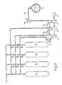
- Figures 2 and 3show modified compressor and storage assemblies, wherein the same reference numerals are utilized for components corresponding to those shown in Figure 1.
- the assembly in Figure 2is a somewhat more sophisticated compressor and storage tank arrangement.
- Three-stage compression with compressors 21, 22 and 23is utilized.
- Storage tankswhich can be operated at pressure levels between zero and up to the maximum delivery pressure of the compressor are used.
- a similar arrangementcould obviously be used for more or for fewer (minimum 2) compressor stages.
- a heat exchanger 19has been introduced upstream of the compressors. This heat exchanger is utilized for optional heating of gases prior to compression. Some types of compressors cannot accept gas which is too cold.
- the intermediate coolersare designated by numerals 24 and 25.
- the necessary valvesare designated by numerals 20, 26, 27, 28, 29, 30 and 31, in addition to the valves 6.
- the illustrated tanks 32 and 33can be single tanks or groups of tanks.
- the purpose of the arrangement shown in Figure 2is to obtain a best possible utilization of the tank storage capacity (for accumulation of boil-off when machinery needs are low), and to minimize the compressor work.
- the pressure in the tanks 32, 33must be as low as possible at the outset.
- the boil-off gasis compressed via first compressor stage 21, cooler 24 and valve 27 to the storage tanks. It should be noted that cut-off valves which may be required at the inlet and outlet of the various compressor stages are not illustrated. When the backpressure has become too great, the next stage is activated by closing the valve 27 and opening the valve 28, etc.
- FIG 3shows an arrangement in which the storage tanks 35 are divided up so that several pressure stages can be utilized simultaneously for storage. Otherwise, the same reference numerals as in Figure 2 are used.
Landscapes
- Engineering & Computer Science (AREA)
- Chemical & Material Sciences (AREA)
- Mechanical Engineering (AREA)
- Combustion & Propulsion (AREA)
- General Engineering & Computer Science (AREA)
- Oil, Petroleum & Natural Gas (AREA)
- Chemical Kinetics & Catalysis (AREA)
- General Chemical & Material Sciences (AREA)
- Ocean & Marine Engineering (AREA)
- Output Control And Ontrol Of Special Type Engine (AREA)
- Filling Or Discharging Of Gas Storage Vessels (AREA)
- Supplying Secondary Fuel Or The Like To Fuel, Air Or Fuel-Air Mixtures (AREA)
Description
- The invention relates to a method for utilizing compressed boil-off gas from cryogenic liquids as fuel in a dual gas/oil-burning diesel engine on board an oceangoing vessel, and to a system for supplying boil-off gas from a cryogenic liquid as fuel to a dual gas/oil-burning diesel engine on board a ship.
- The invention has been especially developed in connection with so-called LNG carriers, i.e., ships which carry natural gas in liquefied form, hereafter termed cryogenic liquid. Gas carriers and especially LNG carriers have a special problem in that heat leaks to the cargo tanks cause the formation of so-called boil-off, i.e., a certain quantity of gas is produced which must be taken care off, either by recondensation or by combustion, or alternately by utilizing the gas as fuel for propulsion and auxiliary machinery.
- With respect to the use of boil-off as fuel on board LNG carriers, the solution most frequently utilized has been to combust the boil-off gas in connection with steam turbine machinery, i.e., as supplementary fuel for the ship boilers, which also burn heavy oil. Operating experience is good with such machinery, but the level of efficiency and bunker fuel consumption are not satisfactory.
- The desire to optimize the fuel economy of propulsion machinery on LNG carriers has focused interest on slow-running ("large-bore") diesel engines. These exhibit very good thermal efficiency, while at the same time they are able to run on poor (inexpensive) quality bunker oil. In connection with the disposal of boil-off from cryogenic liquids in the ship's cargo tanks, the diesel engine alternative immediately presents itself as a very attractive option. At the outset, it would obviously be advantageous if there existed a dual gas/oil-burning diesel engine which could burn gas/heavy oil under any conditions whatsoever and with the same high efficiency over the entire relevant operating spectrum. Such an option would be especially attractive for existing ships where the quantity of boil-off gas produced is high, so that the use of a condensation plant would be disproportionately expensive.
- Pure gas-fueled engines are available today for lower and average output power ranges, i.e., up to some thousand kW. A marine installation also exists which has a slow-running, dual gas/oil-burning diesel engine with an output power of about 15,000 kW.
- In all of these types of engines, the gas is introduced into the combustion chambers or cylinders at moderate pressure immediately after the compression stroke commences. The gas/air mixture is ignited by spark plugs or "pilot" fuel, i.e., a small amount of diesel oil is injected at the moment when combustion is desired. One thereby obtains an almost instantaneous combustion with an accompanying high rise in pressure (the Otto process). Consequently, the amount of gas must be restricted, which in turn results in a reduction of efficiency and a limited capability for combusting gas. In the case of the above-mentioned slow-running (large-bore) diesel engine, the proportion of gas must be held below about 55% of the total fuel requirement at full output power. This means that for larger vessels with large quantities of boil-off, no such suitable dual gas/oil-burning engines exist which can combust all the boil-off gas with sufficient margin and the desirable efficiency.
- There thus exists a need for a dual gas/oil-burning diesel engine which in part can run on pure heavy oil, in part on a high percentage of gas, without unpermissible rises in pressure being produced during combustion. In accordance with the invention, boil-off can be utilized in a dual gas/oil-burning diesel engine under these conditions provided that the boil-off gas is supplied in a controlled manner to the combustion chamber during combustion itself, i.e., one obtains, at any rate approximately, a diesel process.
- In an article of W. Klaunig: "Dual-fuel engines for the propulsion of LNG-tankers", Shipbuilding and Shipping Record, vol. 113, May 30, 1969, pages 742-744, a medium speed dual fuel engine is disclosed. The arrangement for delivery of evaporated natural gas to the engine includes a compressor delivering to an expansion tank. No precautions, however, are taken to insure a controlled supply of boil-off gas to the combustion chamber of the engine during combustion itself.
- According to the invention, therefore, a method for utilizing compressed boil-off gas from cryogenic liquids as fuel in a dual gas/oil-burning diesel engine on board a vessel is provided, which is characterized in that the compressed boil-off gas is introduced into the combustion chamber of the engine during combustion by high pressure injection which is controlled in accordance with the combustion pressure desired revolutions per minute and output power. Preferably, the high-pressure injection is controlled electronically or electronically/hydraulically.
- The technology necessary for carrying out the method is known per se, since experiments have been and continue to be performed with electronically-controlled fuel valves for oil. Also available on the market are diesel engines for special purposes with electronically-controlled delivery of liquid fuel. However, whereas cam-driven fuel pumps can be constructed so that liquid fuel will be injected into the cylinders approximately in sequence with the course of combustion, it is not possible simply to apply this solution for a compressible substance, such as gas is. For both types of fuel, electronic control of the fuel supply provides the best possibilities for monitoring and adjusting the injection in a favorable manner as combustion proceeds.
- The invention also provides a system for supplying boil-off gas from a cryogenic liquid as fuel to a dual gas/oil-burning diesel engine on board a vessel, comprising a gas compressor whose suction side is connected to the storage tank containing the cryogenic liquid, a buffer storage tank which receives compressed gas from the compressor, the system being characterized in that it is further provided with a conduit from the buffer tank to a gas injection valve in the engine combustion chamber, and with a control means for opening and closing the gas injection valve in accordance with the instantaneous pressure in the associated engine combustion chamber. In practice, one can utilize a data processor for administering the most important control impulses, which will be the instantaneous pressure in the cylinder, the revolutions per minute, the desired output power, and the crank position.
- Especially advantageous is a system in which the gas compressor and the buffer storage tank are arranged in the vessel's cargo tank area, since one thereby reduces the safety risks in the vessel's engine room.
- The dual oil/gas-burning diesel engine utilized will have two fuel-supply systems in each cylinder, and each of these is designed for 100% power output. When the engine is running on gas, the gas must be ignited, for example with the aid of pilot fuel, but spark plugs could also be used. Oil/gas in arbitrary ratios can be combusted, and it will normally be preferable to provide reciprocal control so that all the gas available will be combusted at all times with liquid fuel added to whatever degree is necessary. If the output power requirement is so low that there will be excess gas available, the excess can suitably be stored by permitting a build-up of pressure in the cargo tank or tanks. Spherical tanks are especially well- suited in this connection, because they can withstand a certain degree of pressure build-up. This capability may best be utilized if a small amount of gas can be continuously bled off, so as to avoid a rapid rise in pressure of non-condensable gas (nitrogen). It will thus be advantageous to arrange a high pressure storage facility in connection with the buffer storage tank, for example in the form of a battery of gas cylinders. The buffer storage tank may in that case constitute one of the tanks in the battery. Within the limits set by economic and practical considerations, the capacity of the tank battery can be chosen such that the entire amount of boil-off can be allowed to accumulate over a period of several days. When the gas is to be utilized, it is led to a suitable stage in the compressor, which in that case is made as a multistage compressor, this being a favorable solution per se, since the compressor stage may then be selected depending on the pressure at any given time.
- Another way of disposing of boil-off, for instance when the ship is lying up close to land, might be to disconnect the diesel engine from the screw and connect it to a water brake. It might also be practical to utilize a shaft generator, because one can then provide the necessary current requirements by means of especially efficient machinery. In harbor, the screw can be disconnected. The diesel engine must then run on partial loading, but when the fuel is mostly gas, carbonization and other typical problems can better be held under control.
- The invention will be explained in greater detail in the following with reference to the accompanying drawings, wherein:
- Figure 1 shows a schematic drawing of a system in accordance with the invention, and
- Figures 2 and 3 show modified compressor and storage assemblies in accordance with the invention.
- In Figure 1, the cargo tank (spherical tank) on board a vessel is designated by
numeral 1. The boil-off is drawn off at the top of the tank and guided through aline 14 to acompressor 2 which is driven by anelectric motor 3. From the pressure side of thecompressor 2, aline 15 leads to an after-cooler 4, and from the latter aline 16 leads to abuffer storage tank 5. The buffer storage tank hassafety valves 6. From thebuffer storage tank 5, agas line 7 leads to agas injection valve 12 which is connected to the illustrateddiesel engine cylinder 9 and which is opened and closed by means of a control means 13, indicated only schematically in the drawing, which is influenced by the instantaneous pressure in theengine combustion chamber 17, the revolutions per minute, the desired output power and the crank position. - The
cylinder 9 also has afuel valve 10 for ordinary diesel fuel, connected to afuel pump 11. - As shown in the drawing, the
line 7 from thebuffer storage tank 5 passes through aprotective pipe 8 inside the engine room, in accordance with the safety requirements governing gas lines in the engine room of a vessel. Thecompressor 2 and thestorage tank 5, as illustrated, are placed in the cargo tank area, which reduces the safety risks in the engine room. - The compressor may advantageously be a multi-stage compressor with intermediate cooling, and it compresses boil-off gas from the
cargo tank 1 to a suitable pressure, on an order of magnitude of 200 bar. A pressure of this order of magnitude at thevalve 12 is desirable because one will then alway have sufficient margin to the highest combustion pressure. - With the high-pressure gas injection system shown in Figure 1, one can carry out the method of the invention, with controlled high-pressure gas injection provided individually for each engine cylinder.
- Figures 2 and 3 show modified compressor and storage assemblies, wherein the same reference numerals are utilized for components corresponding to those shown in Figure 1.
- The assembly in Figure 2 is a somewhat more sophisticated compressor and storage tank arrangement. Three-stage compression with
compressors - In Figure 2, a
heat exchanger 19 has been introduced upstream of the compressors. This heat exchanger is utilized for optional heating of gases prior to compression. Some types of compressors cannot accept gas which is too cold. - The intermediate coolers are designated by
numerals numerals valves 6. - The illustrated
tanks tanks first compressor stage 21, cooler 24 andvalve 27 to the storage tanks. It should be noted that cut-off valves which may be required at the inlet and outlet of the various compressor stages are not illustrated. When the backpressure has become too great, the next stage is activated by closing thevalve 27 and opening thevalve 28, etc. - When gas is to be used in the machinery, it may happen that the pressure in the storage tanks is so high that compression is not required. For a period of time, in that case, the gas is led via
valve 29 andline 34, etc., to the engine room. If the pressure becomes too low, the gas is first led to thelast compressor stage 23 viavalve 28, and as required an increasing number of the stages are put to use. The arrangement also provides the possibility of storing part of the gas and using the remainder in the machinery, excess gas being drawn off at suitable intermediate stages or following the last stage, depending on the instantaneous pressure in the storage tank. - It should also be mentioned that a more detailed study will indicate the optimum number of compressor stages and the design pressure for the storage tanks. It is not certain that it pays off to dimension these for maximum pressure from the last compressor stage.
- Figure 3 shows an arrangement in which the
storage tanks 35 are divided up so that several pressure stages can be utilized simultaneously for storage. Otherwise, the same reference numerals as in Figure 2 are used.
Claims (4)
Applications Claiming Priority (2)
| Application Number | Priority Date | Filing Date | Title |
|---|---|---|---|
| NO812328ANO812328L (en) | 1981-07-08 | 1981-07-08 | PROCEDURE FOR THE EXPLOITATION OF DECYCLES FROM THE CRYOGENIC LIQUIDS LIKE FUEL IN A TWO-FUEL DIESEL ENGINE, AND SYSTEM FOR USING THE PROCEDURE |
| NO812328 | 1981-07-08 |
Publications (2)
| Publication Number | Publication Date |
|---|---|
| EP0069717A1 EP0069717A1 (en) | 1983-01-12 |
| EP0069717B1true EP0069717B1 (en) | 1985-09-18 |
Family
ID=19886154
Family Applications (1)
| Application Number | Title | Priority Date | Filing Date |
|---|---|---|---|
| EP82850144AExpiredEP0069717B1 (en) | 1981-07-08 | 1982-06-23 | Method for utilizing boil-off gas from cryogenic liquids as fuel in a dual gas/oil-burning diesel engine, and a system for utilizing the method |
Country Status (8)
| Country | Link |
|---|---|
| EP (1) | EP0069717B1 (en) |
| JP (1) | JPS58113536A (en) |
| KR (1) | KR840000732A (en) |
| AU (1) | AU8557582A (en) |
| DE (1) | DE3266371D1 (en) |
| DK (1) | DK279182A (en) |
| FI (1) | FI822422A7 (en) |
| NO (1) | NO812328L (en) |
Cited By (7)
| Publication number | Priority date | Publication date | Assignee | Title |
|---|---|---|---|---|
| WO2003013895A1 (en) | 2001-08-09 | 2003-02-20 | Bayerische Motoren Werke Aktiengesellschaft | Method for operating a motor vehicle fuel tank system, especially a cryotank system and corresponding tank system, for example, for liquid hydrogen |
| DE102005032556A1 (en)* | 2005-07-11 | 2007-01-25 | Atlas Copco Energas Gmbh | Plant and method for using a gas |
| WO2012089891A1 (en) | 2010-12-27 | 2012-07-05 | Wärtsilä Finland Oy | A fuel feeding system and method of operating a fuel feeding system |
| WO2012150379A2 (en) | 2011-05-04 | 2012-11-08 | Wärtsilä Finland Oy | A liquefied gas outlet system, a tank for storing liquefied gas, a method of rebuilding a liquefied gas tank and a method of building a liquefied gas tank |
| DE10202165B4 (en) | 2002-01-22 | 2014-08-21 | Bayerische Motoren Werke Aktiengesellschaft | Motor vehicle with a cryogenic tank |
| CN112524481A (en)* | 2021-02-07 | 2021-03-19 | 河南氢枫能源技术有限公司 | System for recovering vent gas of hydrogenation station |
| WO2025087791A1 (en)* | 2023-10-26 | 2025-05-01 | Phinia Delphi Luxembourg Sarl | Engine system for gaseous fuel |
Families Citing this family (32)
| Publication number | Priority date | Publication date | Assignee | Title |
|---|---|---|---|---|
| GB8425577D0 (en)* | 1984-10-10 | 1984-11-14 | Flintheath Ltd | Fuel control system |
| JPS62131925A (en)* | 1985-12-05 | 1987-06-15 | Mitsubishi Heavy Ind Ltd | Gas feeding unit and gas cooling unit of gas firing diesel engine |
| JPH0654101B2 (en)* | 1987-06-02 | 1994-07-20 | 三菱重工業株式会社 | Gas-fired diesel engine gas supply system |
| FR2653492B1 (en)* | 1989-10-25 | 1994-04-15 | Semt Pielstick | ASSEMBLY OF INTERNAL COMBUSTION ENGINE CYLINDERS FOR THE PROPULSION OF VESSELS CARRYING A FUEL GAS. |
| NO176454C (en)* | 1993-01-29 | 1995-04-05 | Kvaerner Moss Tech As | Methods and plants for utilizing and providing fuel gas, respectively |
| RU2118470C1 (en)* | 1996-07-30 | 1998-08-27 | Анатолий Владимирович Тарасов | Dual-fuel supply system with injector for internal- combustion engine |
| US6095101A (en)* | 1997-01-29 | 2000-08-01 | Man B&W Diesel A/S | Internal combustion engine of the diesel type for combustion of gas, and a method of supplying such an engine with fuel |
| NL1015485C2 (en)* | 2000-06-21 | 2001-12-28 | Petrocare B V | Tanker ship, has sealable pipe extending between hold and engine inlet |
| DE10202172A1 (en)* | 2002-01-22 | 2003-08-07 | Bayerische Motoren Werke Ag | Process for disposing of boil-off gas from a cryogenic tank and motor vehicle operated in this way |
| KR100535553B1 (en)* | 2002-11-12 | 2005-12-08 | 현대자동차주식회사 | Fuel particlization device using purge gas |
| GB0400986D0 (en)* | 2004-01-16 | 2004-02-18 | Cryostar France Sa | Compressor |
| FI122137B (en) | 2006-06-27 | 2011-09-15 | Waertsilae Finland Oy | A fuel system for a gas-powered vessel |
| KR100812723B1 (en)* | 2006-12-18 | 2008-03-12 | 삼성중공업 주식회사 | Fuel supply apparatus and method of liquefied gas carrier |
| GB201001525D0 (en)* | 2010-01-29 | 2010-03-17 | Hamworthy Combustion Eng Ltd | Improvements in or relating to heating |
| KR101239352B1 (en) | 2010-02-24 | 2013-03-06 | 삼성중공업 주식회사 | Floating liquefied natural gas charging station |
| WO2011138988A1 (en)* | 2010-05-07 | 2011-11-10 | 대우조선해양 주식회사 | Electricity generating device of lng carrier and method thereof |
| JP6012140B2 (en)* | 2011-02-25 | 2016-10-25 | 三菱重工業株式会社 | GAS FUEL SUPPLY DEVICE, HIGH PRESSURE GAS INJECTION DIESEL ENGINE, AND LIQUID GAS FUEL SUPPLY METHOD FOR HIGH PRESSURE GAS INJECTION DIESEL ENGINE |
| US8925465B2 (en) | 2012-07-31 | 2015-01-06 | Electro-Motive Diesel, Inc. | Consist having self-propelled tender car |
| US8919259B2 (en) | 2012-07-31 | 2014-12-30 | Electro-Motive Diesel, Inc. | Fuel system for consist having daughter locomotive |
| US9073556B2 (en) | 2012-07-31 | 2015-07-07 | Electro-Motive Diesel, Inc. | Fuel distribution system for multi-locomotive consist |
| US9193362B2 (en) | 2012-07-31 | 2015-11-24 | Electro-Motive Diesel, Inc. | Consist power system having auxiliary load management |
| US8899158B2 (en) | 2012-07-31 | 2014-12-02 | Electro-Motive Diesel, Inc. | Consist having self-powered tender car |
| US8960100B2 (en) | 2012-07-31 | 2015-02-24 | Electro-Motive Diesel, Inc. | Energy recovery system for a mobile machine |
| US8955444B2 (en) | 2012-07-31 | 2015-02-17 | Electro-Motive Diesel, Inc. | Energy recovery system for a mobile machine |
| WO2014086414A1 (en) | 2012-12-05 | 2014-06-12 | Blue Wave Co S.A. | Dual-fuel feed circuit system using compressed natural gas for dual-feed converted ship engines, and integration thereof in a cng marine transportation system |
| JP6228060B2 (en)* | 2014-03-31 | 2017-11-08 | 三井造船株式会社 | Fuel gas supply device |
| JP6322155B2 (en)* | 2015-04-30 | 2018-05-09 | 三井造船株式会社 | Fuel gas supply system for liquefied gas carrier |
| CN104963777B (en)* | 2015-07-13 | 2018-04-27 | 中船动力有限公司 | Engine gas valve set system and control method |
| ES2628277B2 (en)* | 2016-02-02 | 2017-12-29 | Universidade Da Coruña | Hydrogen generation plant for on-board installation of LNG ships |
| DE102016220822A1 (en)* | 2016-10-24 | 2018-04-26 | Robert Bosch Gmbh | Bubble-free low-pressure pump for liquefied gas |
| CN110762383B (en)* | 2019-10-29 | 2022-06-21 | 雒高龙 | System for recycling liquid cargo tank evaporated gas by using tube bundle type high-pressure gas cylinder set |
| GB2634930A (en)* | 2023-10-26 | 2025-04-30 | Phinia Delphi Luxembourg Sarl | Engine system for gaseous fuel |
Family Cites Families (2)
| Publication number | Priority date | Publication date | Assignee | Title |
|---|---|---|---|---|
| GB1440318A (en)* | 1972-12-08 | 1976-06-23 | Conch Int Methane Ltd | Liquefied gas tankers |
| DE3026097A1 (en)* | 1980-07-10 | 1982-02-18 | Robert Bosch Gmbh, 7000 Stuttgart | CONTROL DEVICE FOR CONTROL SIZES OF AN INTERNAL COMBUSTION ENGINE |
- 1981
- 1981-07-08NONO812328Apatent/NO812328L/enunknown
- 1982
- 1982-06-22DKDK279182Apatent/DK279182A/ennot_activeApplication Discontinuation
- 1982-06-23DEDE8282850144Tpatent/DE3266371D1/ennot_activeExpired
- 1982-06-23EPEP82850144Apatent/EP0069717B1/ennot_activeExpired
- 1982-07-02AUAU85575/82Apatent/AU8557582A/ennot_activeAbandoned
- 1982-07-07KRKR1019820003023Apatent/KR840000732A/ennot_activeWithdrawn
- 1982-07-07JPJP57117063Apatent/JPS58113536A/enactivePending
- 1982-07-07FIFI822422Apatent/FI822422A7/ennot_activeApplication Discontinuation
Cited By (9)
| Publication number | Priority date | Publication date | Assignee | Title |
|---|---|---|---|---|
| WO2003013895A1 (en) | 2001-08-09 | 2003-02-20 | Bayerische Motoren Werke Aktiengesellschaft | Method for operating a motor vehicle fuel tank system, especially a cryotank system and corresponding tank system, for example, for liquid hydrogen |
| DE10202165B4 (en) | 2002-01-22 | 2014-08-21 | Bayerische Motoren Werke Aktiengesellschaft | Motor vehicle with a cryogenic tank |
| DE102005032556A1 (en)* | 2005-07-11 | 2007-01-25 | Atlas Copco Energas Gmbh | Plant and method for using a gas |
| DE102005032556B4 (en)* | 2005-07-11 | 2007-04-12 | Atlas Copco Energas Gmbh | Plant and method for using a gas |
| WO2012089891A1 (en) | 2010-12-27 | 2012-07-05 | Wärtsilä Finland Oy | A fuel feeding system and method of operating a fuel feeding system |
| WO2012150379A2 (en) | 2011-05-04 | 2012-11-08 | Wärtsilä Finland Oy | A liquefied gas outlet system, a tank for storing liquefied gas, a method of rebuilding a liquefied gas tank and a method of building a liquefied gas tank |
| CN112524481A (en)* | 2021-02-07 | 2021-03-19 | 河南氢枫能源技术有限公司 | System for recovering vent gas of hydrogenation station |
| CN112524481B (en)* | 2021-02-07 | 2021-06-01 | 河南氢枫能源技术有限公司 | System for recovering vent gas of hydrogenation station |
| WO2025087791A1 (en)* | 2023-10-26 | 2025-05-01 | Phinia Delphi Luxembourg Sarl | Engine system for gaseous fuel |
Also Published As
| Publication number | Publication date |
|---|---|
| KR840000732A (en) | 1984-02-27 |
| FI822422A0 (en) | 1982-07-07 |
| FI822422L (en) | 1983-01-09 |
| NO812328L (en) | 1983-01-10 |
| DE3266371D1 (en) | 1985-10-24 |
| DK279182A (en) | 1983-01-09 |
| FI822422A7 (en) | 1983-01-09 |
| AU8557582A (en) | 1983-01-13 |
| EP0069717A1 (en) | 1983-01-12 |
| JPS58113536A (en) | 1983-07-06 |
Similar Documents
| Publication | Publication Date | Title |
|---|---|---|
| EP0069717B1 (en) | Method for utilizing boil-off gas from cryogenic liquids as fuel in a dual gas/oil-burning diesel engine, and a system for utilizing the method | |
| CN101952635B (en) | Natural gas supply method and apparatus | |
| US6286480B1 (en) | Reduced emissions elevated altitude diesel fuel injection timing control | |
| SU543360A3 (en) | Installation for the secondary liquefaction of gas | |
| KR100396471B1 (en) | A method of controlling fuel supply to a diesel engine to which both fuel oil and fuel gas can be supplied by high-pressure injection, and a method of controlling the fuel supply to the diesel- | |
| US3720057A (en) | Method of continuously vaporizing and superheating liquefied cryogenic fluid | |
| KR102455808B1 (en) | Large two-stroke uniflow scavenged gaseous fueled engine | |
| KR102058380B1 (en) | A large two-stroke compression-ignited internal combustion engine with dual fuel systems | |
| JP2024138057A (en) | Fuel supply system for a large two-stroke compression ignition high pressure gas injection internal combustion engine | |
| WO2013032340A1 (en) | System and method for boosting bog in a lng fuel system | |
| WO1984001339A1 (en) | A device, a procedure and employment concerning diesel engines using two different fuels and employment of the device for starting such engines | |
| RU2696145C1 (en) | Method and device for treating evaporated gas for feeding at least to an engine | |
| KR101622754B1 (en) | An internal combustion engine, and a method of supplying such engine with gaseous fuel | |
| US5035115A (en) | Energy conserving engine | |
| KR102315522B1 (en) | Gaseous fuel supply system and method for operating the gaseous fuel supply system | |
| KR102710835B1 (en) | Fuel gas supply system and ship including the same | |
| KR102846151B1 (en) | liquefied gas treatment system and ship having the same | |
| Bahgat et al. | Performance analysis of different propulsion systems for LNG carriers | |
| Clausen | Alternative propulsion for LNG ships by low speed ME-C and ME-GI engines | |
| Skjoldager | Propulsion of LNG Carriers by MAN B&W Two-Stroke Diesel Engines-ME and ME-GI Diesel Engines for LNG Carriers |
Legal Events
| Date | Code | Title | Description |
|---|---|---|---|
| PUAI | Public reference made under article 153(3) epc to a published international application that has entered the european phase | Free format text:ORIGINAL CODE: 0009012 | |
| AK | Designated contracting states | Designated state(s):BE CH DE FR GB IT LI NL SE | |
| 17P | Request for examination filed | Effective date:19830627 | |
| ITF | It: translation for a ep patent filed | ||
| GRAA | (expected) grant | Free format text:ORIGINAL CODE: 0009210 | |
| AK | Designated contracting states | Designated state(s):BE CH DE FR GB IT LI NL SE | |
| PG25 | Lapsed in a contracting state [announced via postgrant information from national office to epo] | Ref country code:NL Effective date:19850918 Ref country code:BE Effective date:19850918 | |
| REF | Corresponds to: | Ref document number:3266371 Country of ref document:DE Date of ref document:19851024 | |
| NLV1 | Nl: lapsed or annulled due to failure to fulfill the requirements of art. 29p and 29m of the patents act | ||
| PG25 | Lapsed in a contracting state [announced via postgrant information from national office to epo] | Ref country code:GB Effective date:19860623 | |
| PG25 | Lapsed in a contracting state [announced via postgrant information from national office to epo] | Ref country code:SE Effective date:19860624 | |
| PLBI | Opposition filed | Free format text:ORIGINAL CODE: 0009260 | |
| EN | Fr: translation not filed | ||
| 26 | Opposition filed | Opponent name:GEBRUEDER SULZER AKTIENGESELLSCHAFT Effective date:19860614 | |
| REG | Reference to a national code | Ref country code:CH Ref legal event code:PL | |
| GBPC | Gb: european patent ceased through non-payment of renewal fee | ||
| RDAG | Patent revoked | Free format text:ORIGINAL CODE: 0009271 | |
| STAA | Information on the status of an ep patent application or granted ep patent | Free format text:STATUS: PATENT REVOKED | |
| 27W | Patent revoked | Effective date:19861117 | |
| EUG | Se: european patent has lapsed | Ref document number:82850144.5 Effective date:19870505 |