EP0069350B1 - Medication infusion device - Google Patents
Medication infusion deviceDownload PDFInfo
- Publication number
- EP0069350B1 EP0069350B1EP82105880AEP82105880AEP0069350B1EP 0069350 B1EP0069350 B1EP 0069350B1EP 82105880 AEP82105880 AEP 82105880AEP 82105880 AEP82105880 AEP 82105880AEP 0069350 B1EP0069350 B1EP 0069350B1
- Authority
- EP
- European Patent Office
- Prior art keywords
- fingers
- cap
- finger
- cam
- feeding tube
- Prior art date
- Legal status (The legal status is an assumption and is not a legal conclusion. Google has not performed a legal analysis and makes no representation as to the accuracy of the status listed.)
- Expired
Links
- 238000001802infusionMethods0.000titleclaimsdescription41
- 229940079593drugDrugs0.000titleclaimsdescription28
- 239000003814drugSubstances0.000titleclaimsdescription28
- 239000007788liquidSubstances0.000claimsdescription21
- 238000005086pumpingMethods0.000claimsdescription7
- 239000000463materialSubstances0.000claimsdescription5
- 229920001887crystalline plasticPolymers0.000claimsdescription4
- 229930182556PolyacetalNatural products0.000claimsdescription3
- 229920006324polyoxymethylenePolymers0.000claimsdescription3
- NOESYZHRGYRDHS-UHFFFAOYSA-NinsulinChemical compoundN1C(=O)C(NC(=O)C(CCC(N)=O)NC(=O)C(CCC(O)=O)NC(=O)C(C(C)C)NC(=O)C(NC(=O)CN)C(C)CC)CSSCC(C(NC(CO)C(=O)NC(CC(C)C)C(=O)NC(CC=2C=CC(O)=CC=2)C(=O)NC(CCC(N)=O)C(=O)NC(CC(C)C)C(=O)NC(CCC(O)=O)C(=O)NC(CC(N)=O)C(=O)NC(CC=2C=CC(O)=CC=2)C(=O)NC(CSSCC(NC(=O)C(C(C)C)NC(=O)C(CC(C)C)NC(=O)C(CC=2C=CC(O)=CC=2)NC(=O)C(CC(C)C)NC(=O)C(C)NC(=O)C(CCC(O)=O)NC(=O)C(C(C)C)NC(=O)C(CC(C)C)NC(=O)C(CC=2NC=NC=2)NC(=O)C(CO)NC(=O)CNC2=O)C(=O)NCC(=O)NC(CCC(O)=O)C(=O)NC(CCCNC(N)=N)C(=O)NCC(=O)NC(CC=3C=CC=CC=3)C(=O)NC(CC=3C=CC=CC=3)C(=O)NC(CC=3C=CC(O)=CC=3)C(=O)NC(C(C)O)C(=O)N3C(CCC3)C(=O)NC(CCCCN)C(=O)NC(C)C(O)=O)C(=O)NC(CC(N)=O)C(O)=O)=O)NC(=O)C(C(C)CC)NC(=O)C(CO)NC(=O)C(C(C)O)NC(=O)C1CSSCC2NC(=O)C(CC(C)C)NC(=O)C(NC(=O)C(CCC(N)=O)NC(=O)C(CC(N)=O)NC(=O)C(NC(=O)C(N)CC=1C=CC=CC=1)C(C)C)CC1=CN=CN1NOESYZHRGYRDHS-UHFFFAOYSA-N0.000description26
- 102000004877InsulinHuman genes0.000description13
- 108090001061InsulinProteins0.000description13
- 229940125396insulinDrugs0.000description13
- 230000006870functionEffects0.000description5
- 238000004519manufacturing processMethods0.000description5
- 239000005060rubberSubstances0.000description5
- -1polyethylenePolymers0.000description4
- 230000009467reductionEffects0.000description4
- 244000060701Kaempferia pandurataSpecies0.000description3
- 235000016390Uvaria chamaeNutrition0.000description3
- 230000004048modificationEffects0.000description3
- 238000012986modificationMethods0.000description3
- 230000002572peristaltic effectEffects0.000description3
- 239000004698PolyethyleneSubstances0.000description2
- 239000004743PolypropyleneSubstances0.000description2
- 230000006835compressionEffects0.000description2
- 238000007906compressionMethods0.000description2
- 230000000694effectsEffects0.000description2
- 238000005265energy consumptionMethods0.000description2
- 230000005057finger movementEffects0.000description2
- 238000002347injectionMethods0.000description2
- 239000007924injectionSubstances0.000description2
- 235000012054mealsNutrition0.000description2
- 238000000034methodMethods0.000description2
- 238000000465mouldingMethods0.000description2
- 230000002093peripheral effectEffects0.000description2
- 229920002647polyamidePolymers0.000description2
- 229920000573polyethylenePolymers0.000description2
- 229920001155polypropylenePolymers0.000description2
- 230000008569processEffects0.000description2
- YCKRFDGAMUMZLT-UHFFFAOYSA-NFluorine atomChemical compound[F]YCKRFDGAMUMZLT-UHFFFAOYSA-N0.000description1
- 239000004952PolyamideSubstances0.000description1
- 230000009471actionEffects0.000description1
- 230000004913activationEffects0.000description1
- 239000000853adhesiveSubstances0.000description1
- 230000001070adhesive effectEffects0.000description1
- 230000006399behaviorEffects0.000description1
- 230000008859changeEffects0.000description1
- 238000010276constructionMethods0.000description1
- 239000013078crystalSubstances0.000description1
- 125000004122cyclic groupChemical group0.000description1
- 206010012601diabetes mellitusDiseases0.000description1
- 238000010586diagramMethods0.000description1
- 230000003292diminished effectEffects0.000description1
- 229910052731fluorineInorganic materials0.000description1
- 239000011737fluorineSubstances0.000description1
- 238000009434installationMethods0.000description1
- 230000002452interceptive effectEffects0.000description1
- 230000005923long-lasting effectEffects0.000description1
- 238000003754machiningMethods0.000description1
- 239000002184metalSubstances0.000description1
- 239000004033plasticSubstances0.000description1
- 229920003023plasticPolymers0.000description1
- 239000002985plastic filmSubstances0.000description1
- 229920000642polymerPolymers0.000description1
- 230000008707rearrangementEffects0.000description1
- 230000001105regulatory effectEffects0.000description1
- 239000011347resinSubstances0.000description1
- 229920005989resinPolymers0.000description1
Images


Classifications
- A—HUMAN NECESSITIES
- A61—MEDICAL OR VETERINARY SCIENCE; HYGIENE
- A61M—DEVICES FOR INTRODUCING MEDIA INTO, OR ONTO, THE BODY; DEVICES FOR TRANSDUCING BODY MEDIA OR FOR TAKING MEDIA FROM THE BODY; DEVICES FOR PRODUCING OR ENDING SLEEP OR STUPOR
- A61M5/00—Devices for bringing media into the body in a subcutaneous, intra-vascular or intramuscular way; Accessories therefor, e.g. filling or cleaning devices, arm-rests
- A61M5/14—Infusion devices, e.g. infusing by gravity; Blood infusion; Accessories therefor
- A61M5/142—Pressure infusion, e.g. using pumps
- A61M5/14212—Pumping with an aspiration and an expulsion action
- A61M5/14228—Pumping with an aspiration and an expulsion action with linear peristaltic action, i.e. comprising at least three pressurising members or a helical member
Definitions
- This inventionrelates to a device for infusion of liquid medication having a finger-type pump unit, said pump unit having a cap and three or more fingers displaceable towards said cap in a predetermined sequence by operation of cam means driven by rotary drive means, said fingers being operative to squeeze a feeding tube for infusion of medication, said feeding tube being placed between said cap and said fingers, said three or more fingers comprise two side fingers placed in side-by-side relation with at least one inner or central finger, said side fingers having a valving function and being capable of squeezing said tube at substantially one point and said central finger having a pumping function and being capable of squeezing said feeding tube over a required length, and said cam means comprising a plurality of cams each having a specific cam profile and operatively associated with each said finger for operating said finger, said cams being mounted coaxially in the sidewise direction of said fingers.
- An infusion device of the type describedhas been proposed for infusion of a small amount of medication such as insulin.
- a small amount of medicationsuch as insulin.
- insulinfor example, in the treatment of a diabetic patient, it is necessary that insulin be continuously and cyclically infused into the body of the patient. Since the insulin requirement of a patient is subject to substantial fluctuations caused by the meal cycle, sleep or energy consumption as when the patient walks, a small-sized portable insulin infusion device has been proposed in which prescribed infusion doses are preset for certain times so that cyclic insulin infusion may be made in accordance with the insulin requirements of the body that change with time.
- the infusion device defined abovemay be applied to the proposed insulin infusion device.
- the insulin infusion devicehas a memory in which the amount of liquid infused per unit time may be programmed on the basis of the presumed physical condition and behavior of the patient over a twenty-four hour period.
- the devicealso has a clock generator for generating clock for calling data from memory at predetermined time intervals, and a motor drive circuit for rotating a motor a certain number of revolutions conforming to the data called forth from the memory by the clock.
- the pump unit and the pump control unitmay be enclosed in respective casings.
- the pump unitacts to dispense the liquid by squeezing or collapsing the feeding tube of a disposable insulin vessel and may operate for a required time interval such as one minute as instructed by the pump control unit for dispensing the required insulin dose programmed in the memory.
- the infusion device of this kindmay be applied not only to the infusion of insulin but also to any repeated and continued infusion treatment in which liquid medication is administered in equal or differing doses per time unit.
- the prior-art pumpdoes not lend itself to a reduction in size easily because of the large number of components and numerous assembly steps. Moreover, a small-sized pump exhibits diminished durability, while the amount of dispensed liquid cannot be adjusted minutely without considerable difficulties. Thus it is not easy to obtain an infusion device by using a small sized version of the prior-art pump.
- Fig. 1showing a prior-art finger type pump unit
- Cdenotes a feeding tube
- 2denotes finger guides
- 4denotes a cam shaft
- 6denotes a cap and 7 a casing.
- Liquidmay be dispensed by sequential actuation in the liquid feed direction of the fingers capable of squeezing the tube C. At least three fingers 1 are required in this case, but a larger number of fingers 1 are required to dispense the liquid smoothly.
- the number of cams 3 and coil springs 5 requiredis the same as that of the fingers 1.
- a device for infusion of liquid medication as defined in the beginningis known from GB-A-2 000 833.
- the fingersare arranged and moved as shown in Fig. 1. Therefore, finger guides are necessary and energy losses because of friction between the fingers and finger guides are inevitable.
- the present inventionhas been devised with the foregoing in view and has as its object to provide a medication infusion device having a finger-type pump unit which is small in size and light in weight and durable in construction, and which has a markedly reduced energy consumption.
- the foregoing objectis attained by providing a medication infusion device of the type mentioned which is characterized in that said fingers are mounted at adjacent ends in a cantilever fashion.
- a support member for mounting said fingers, said cap and said camsis formed as a support frame encircling said fingers in substantially the same plane as said fingers.
- a flexible control sheetis placed directly on the surface of said cap facing said central finger, said sheet is secured to said cap at one end thereof opposite to a portion of said cap that abuts against said feeding tube, which sheet is not secured at the other end, so that said abutment portion may be urged in the direction of said feeding tube.
- each of said fingershas a plate spring portion at said end thereof, said plate spring portion having a reduced thickness in the direction of said cap and the cam.
- Figs. 2, 3 and 4show a small-sized portable medication infusion device suitably employed as an insulin injection device.
- the deviceincludes a casing 8 enclosing a pump unit 9, a pump control unit 10, a battery 11 and a disposable medication bag 12, and may be hermetically sealed by a cover 13.
- the deviceis so constructed that, upon activation of a switch (not shown) to turn on the battery 11, different commands stored in memory are sent to the pump control unit 10 at predetermined time intervals so that the pump 9 operates to squeeze or collapse a feeding tube 14 repeatedly to dispense the medication from the medication bag into a catheter (not shown) inserted into the human body.
- the pump unit 9may be controlled by any of a variety of control means including on/off switching devices for the power source, or automatic control means aided by microcomputers.
- the unit 9preferably is contained in a casing along with the pump control unit 10, but these components may also be contained in separate vessels.
- the pump unit 9need not be constructed to enclose the disposable medication bag 12, it being only necessary that the feeding tube 14 be sandwiched and collapsed or squeezed to effect infusion of the liquid medication.
- the pump unit 9must have rotary drive means 15 such as a motor.
- rotary drive means 15such as a motor.
- An arrangementwill suffice in which the feeding tube 14 of the medication bag 12 is placed between a cap 20 and fingers that are peristaltically moved by operation of a cam 16 driven in turn by the rotary drive means 15.
- the feeding tube 14is squeezed by the fingers to effect liquid infusion.
- the three fingers 17, 18, 19are placed side-by-side and the side fingers 17, 19 are of lesser width than the central finger, so that the feeding tube 14 may be collapsed substantially by point engagement to reduce the force required to completely collapse the tube and, hence, to lighten the burden of the drive system.
- the inner or central finger 18is of larger width so as to have a pumping capability to collapse the tube 14 over a required length, in order to afford an effective peristaltic liquid feeding function with the use of a minimum number of fingers so as to reduce the number of components and manufacturing steps.
- the fingers 17, 18, 19are surrounded by a box-shaped support frame 21 on which the fingers 17, 18, 19, the cap 20 and the cam 16 are mounted.
- the support frame 21is divided into upper frame sections 21 a facing the fingers 21 and tower frame sections 21 b facing the lower surface of a cam 16, and is adapted to hold the cam 16 on either side by bearings 22, 23. These bearings are used to reduce power loss in the drive system.
- the cam 16is formed as one piece with a common axis.
- the cam 16has end cam portions 16a, 16c of maximum radii which are smaller than the minimum radius of the axially central cam portion 16b, as shown in Fig. 3. With such a cam profile, the cam can be extracted from the mold in the axial direction when molded as one piece to reduce assembly error, so that loss of motive power due to friction with the fingers caused by burrs or like irregularities on the cam surface may be prevented. As shown in Figs. 6, 7 and 8, the upper frame sections 21a are formed integrally with fingers 17, 18, 19, and the cantilevered end portions of the fingers 17, 18, 19 are reduced in thickness in the direction of the cap and cam and are arranged as plate spring portions 24.
- the purpose of such structureis to enhance machining and assembly precision through integral molding- and to free the fingers for the purpose of reducing power loss caused by friction with finger guides.
- Longitudinally extending slits 25, 26 facing the cap 20are provided in the faces of the frame portion adjacent to the fingers 17, 19, while a slit 17 is provided in the upper surface of the casing 8 facing the pump unit 9.
- the purpose of such structureis to stabilize the disposable medication bag 12 by being linearly positioned in the slits 25, 26, 27.
- the cap 20is pivotally mounted by a pin shaft 28 to one side of the support frame section 21a.
- the caphas a screw 29 which may be engaged with or disengaged from a tapped hole 30 in the frame portion 21 a towards the finger root for opening or closing the cap.
- a flexible metal or plastic sheet 31is mounted on the surface of the cap 20 facing the fingers, so as to be intimately contactable with the central finger 18, and is secured to cap 20 with a screw 32 or an adhesive at an end portion of the sheet 31 free from contact with the feeding tube 14.
- An adjustment screw 33 operable from the cap side of the sheet 31is threadably mounted through sheet 31 at the position contactable with feeding tube 14. The purpose of such structure is to adjust the gap by adjustment of the screw 33 and, hence, to adjust the extent to which the feeding tube 14 is squeezed, thereby regulating the flow of liquid medication.
- the preferred degree of adjustmentis such as will not completely collapse the feeding tube 14, in order to provide smooth and durable restoration of the tube.
- Rubber segments 34, 35are mounted on the same surface of the cap 20 and at positions registering with the side fingers 17, 19 and abutt- able on the feeding tube 14, in order to provide smooth and durable tube restoration and to prevent the fracture of the feeding tube 14 if the feeding tube is crushed completely by the side fingers 17, 19 over a number of times.
- the minimum gap between the rubber segments and the side fingersis selected to be considerably less than twice the standard tube thickness to allow for compression of the rubber segments to a corresponding amount so that the tube can be squeezed fully in spite of fluctuations in tube thickness. The lesser the tube thickness, the lesser the amount of compression of the rubber plate.
- the cam 16is formed integrally of end cam portions 16a, 16c slidably engaged with side fingers 17, 19, central cam portion 16b slidably engaged with central finger 18 and a sensing plate 16d having equiangular peripheral slits for sensing the number of motor revolutions. Adopting such an integral molding operation is useful in reducing the number of components and manufacturing steps and in increasing productivity and assembly accuracy.
- Cam portions 16a, 16b, 16chave different cam profiles of the desired shape, e.g. eccentric circles.
- the cam portion 16bhas a minimum radius which is more than the maximum radius of the cam portions 16a, 16c, it is possible to extract the metallic mold axially of the cam so that the cam can be molded integrally without forming burrs on the cam surface, so that there little loss of driving power.
- the correlation of these cam profilesare selected so that the fingers 17 to 19 may be peristaltically displaced as shown in Fig. 14 or 15 for the tube squeezing process.
- the cam 16, fingers 17, 18, 19 and the support frame 21are molded from highly wear- resistant plastic materials such as polyacetal, polyamid, polyethylene, polypropylene or fluorine resin, in order to prevent wear due to sliding contact between the cam 16 and the fingers 17, 18, 19 and to assure a long-lasting pumping function.
- Each leaf spring portion 24 of the thin-walled finger roothas a rectangular cross- section.
- the lower frame portion 21bhas finger guides 36, 37, 38, 39 adapted to enter the gaps on both sides and between the fingers 17, 18, 19 in order to prevent the fingers 17, 18, 19 from interfering with each other due to flexure of the fingers caused by the cam portions 16a, 16b, 16c.
- the finger guides of the present inventionare not ordinarily in contact with the fingers, unlike the guides used in the conventional device, and may be used advantageously with a battery- driven injection device because no loss of driving power results from frictional contact with the guide during the finger operation.
- the rotary drive means 15is a miniature coreless motor fitted with a reduction gear and clamped in position by an upper mounting plate 40a and a lower mounting plate 40b to facilitate the assembly operation.
- the upper mounting plate 40ais formed integrally with the upper frame sections 21a while the lower mounting plate 40b is formed integrally with the lower frame sections 21 b.
- the purpose of such integral moldingis to reduce the number of components, to enable the components to be manufactured with great accuracy and uniformity and to maintain assembly precision.
- Elongate slits 41, 42are provided respectively in the connecting portion between the plate 40a and frame sections 21a and in the connecting portion between the plate 40a and frame sections 21 b for absorbing looseness or mounting error between the motor 15 and mounting plates 40a, 40b, and for assuring smooth motor operation.
- the coreless motor 15has an output shaft 15a which intrudes into an axial bore in the cam 16 and is connected thereto by a pin 43.
- a light emitter 44 and a light receiver 45are mounted on both sides of and in opposition to the peripheral slits in the sensing plate 16d of the cam 16 for supplying the pump control unit 10 with feedback signals indicative of the number of revolutions of the cam 16.
- the cam 16is fit on the lower frame sections 21b along with the bearings 22, 23 disposed on either side of the cam 16.
- the output shaft 15aWith the neck of the output shaft 15a of the motor 15 placed on the lower mounting plate 40b, the output shaft 15a is inserted into the axial bore 16e of the cam 16, and the pin 43 is driven in place for connecting the cam 16 to the motor 15.
- the upper frame sections 21aare placed on the lower frame sections 21 b and connected thereto by a screw 47.
- the upper mounting plate 40ais secured in place by a screw 48.
- the support frame 21is placed on base blocks 8a, 8b provided on the bottom surface of the casing 8 and is secured thereto by a screw 46.
- the cap 20 with built-in gap adjustment sheet 31, adjustment screw 33, screw 29 and rubber segments 34, 35is pivotally mounted by pin shaft 28 on the upper frame portion 21a. According to the present invention, adjustment of the cam 16 and fingers 17, 18, 19 is unnecessary.
- control unit 10In using the device, a disposable bag 12 is placed in the casing, the cap 20 is opened, the feeding tube 14 is laid in the slits 25, 26, 27 and on the fingers 17, 18, 19, and the cover casing 13 is closed. Then, as the power source is turned on, control unit 10 is driven into operation by power supplied by the battery.
- the control unit 10has a memory, a clock for calling data from the memory and a motor driving circuit designed to rotate the motor a certain number of revolutions commensurate with the data obtained from the memory.
- the clockis active at all times and calls the specified memory locations after the lapse of a predetermined unit time such as one minute.
- the memorystores a program defining the infusion dose per minute determined beforehand and based upon the patient's meal time, ambulation and sleep or rest periods. Thus the memory issues the specified signal called by the clock.
- the motor drive circuitconverts the signal into a form indicative of motor revolution and delivers the converted signal at one-minute intervals for driving the motor 15 of the pump unit 9 accordingly. In the present embodiment, the memory locations addressed are changed at intervals of 15 minutes.
- the pump unit 9then operates to squeeze the tube 14 repeatedly to dispense the medication in the bag 12 into the catheter inserted into the patient's body.
- the medication infusion device of the present invention having the finger-type pump unitis not limited to the above embodiment of the invention, but may be modified in a number of ways. Specifically, the finger-type pump unit to be employed in the present invention may be subjected to the following modifications:
- the infusion device of the present inventioncomprises a finger-type pump unit in which a feeding tube is sandwiched between three or more fingers and the cap and squeezed thereby to dispense the medication, wherein both side fingers of lesser width and one or two or more inner or central fingers of greater width are supported by plate spring portions in cantilevered fashion so that the fingers are peristaltically displaced by a cam formed as a unitary body with a common axis.
- the finger guides in the pump unitmay be omitted to improve durability and cut power consumption by eliminating frictionally engaging parts.
- the support framewhen the support frame is divided into upper and lower frame sections encircling the fingers, cam assembly operation can be facilitated considerably.
- the fingers and the support frameare molded integrally and the finger roots are reduced in thickness so as to be used as plate spring portions, the number of components in the device can be minimized and the dimensional and assembly precision improved to offset the higher costs entailed by metallic molds.
- the fingersare oscillable by pins or connected by metallic plates to the support frame, then the metallic molds for the fingers and the frame can be simplified. Adjustment of the dispensed liquid dose is facilitated when the gap control sheet is affixed to the inner surface of the cap and flexed by the screw to provide an adjustable gap between it and the central finger.
- mounting plates for rotary drive meanssuch as motors are formed integrally with the support frame and the connecting portions are formed with slits, the number of components can be minimized with a facilitated assembly operation.
Landscapes
- Health & Medical Sciences (AREA)
- Vascular Medicine (AREA)
- Engineering & Computer Science (AREA)
- Anesthesiology (AREA)
- Biomedical Technology (AREA)
- Heart & Thoracic Surgery (AREA)
- Hematology (AREA)
- Life Sciences & Earth Sciences (AREA)
- Animal Behavior & Ethology (AREA)
- General Health & Medical Sciences (AREA)
- Public Health (AREA)
- Veterinary Medicine (AREA)
- Infusion, Injection, And Reservoir Apparatuses (AREA)
- External Artificial Organs (AREA)
Description
- This invention relates to a device for infusion of liquid medication having a finger-type pump unit, said pump unit having a cap and three or more fingers displaceable towards said cap in a predetermined sequence by operation of cam means driven by rotary drive means, said fingers being operative to squeeze a feeding tube for infusion of medication, said feeding tube being placed between said cap and said fingers, said three or more fingers comprise two side fingers placed in side-by-side relation with at least one inner or central finger, said side fingers having a valving function and being capable of squeezing said tube at substantially one point and said central finger having a pumping function and being capable of squeezing said feeding tube over a required length, and said cam means comprising a plurality of cams each having a specific cam profile and operatively associated with each said finger for operating said finger, said cams being mounted coaxially in the sidewise direction of said fingers.
- An infusion device of the type described has been proposed for infusion of a small amount of medication such as insulin. For example, in the treatment of a diabetic patient, it is necessary that insulin be continuously and cyclically infused into the body of the patient. Since the insulin requirement of a patient is subject to substantial fluctuations caused by the meal cycle, sleep or energy consumption as when the patient walks, a small-sized portable insulin infusion device has been proposed in which prescribed infusion doses are preset for certain times so that cyclic insulin infusion may be made in accordance with the insulin requirements of the body that change with time. The infusion device defined above may be applied to the proposed insulin infusion device.
- The insulin infusion device has a memory in which the amount of liquid infused per unit time may be programmed on the basis of the presumed physical condition and behavior of the patient over a twenty-four hour period. The device also has a clock generator for generating clock for calling data from memory at predetermined time intervals, and a motor drive circuit for rotating a motor a certain number of revolutions conforming to the data called forth from the memory by the clock. The pump unit and the pump control unit may be enclosed in respective casings. The pump unit acts to dispense the liquid by squeezing or collapsing the feeding tube of a disposable insulin vessel and may operate for a required time interval such as one minute as instructed by the pump control unit for dispensing the required insulin dose programmed in the memory.
- The infusion device of this kind may be applied not only to the infusion of insulin but also to any repeated and continued infusion treatment in which liquid medication is administered in equal or differing doses per time unit.
- The prior-art pump does not lend itself to a reduction in size easily because of the large number of components and numerous assembly steps. Moreover, a small-sized pump exhibits diminished durability, while the amount of dispensed liquid cannot be adjusted minutely without considerable difficulties. Thus it is not easy to obtain an infusion device by using a small sized version of the prior-art pump.
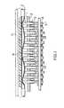
- Referring now to Fig. 1 showing a prior-art finger type pump unit, C denotes a feeding tube, 1, 1... denote fingers, 2 denotes finger guides, 3, 3... denote cams, 4 denotes a cam shaft, 5, 5... denote coil springs, 6 denotes a cap and 7 a casing. Liquid may be dispensed by sequential actuation in the liquid feed direction of the fingers capable of squeezing the tube C. At least three fingers 1 are required in this case, but a larger number of fingers 1 are required to dispense the liquid smoothly. The number of cams 3 and
coil springs 5 required is the same as that of the fingers 1. Thus a large number of components and manufacturing steps are required and space must be provided for housing and assembly of these components, thus making it difficult to reduce the size of the pump unit and infusion device. Furthermore, adjustment of the amount of liquid dispensed per revolution of the cam shaft of the finger-type pump unit is practically impossible due to structural limitation. Also, loss of electrical power due to friction between a multiplicity of fingers and finger guides cannot be neglected in view of the limited power supply of the portable type infusion device. - A device for infusion of liquid medication as defined in the beginning is known from GB-A-2 000 833. Here, too, the fingers are arranged and moved as shown in Fig. 1. Therefore, finger guides are necessary and energy losses because of friction between the fingers and finger guides are inevitable.
- The present invention has been devised with the foregoing in view and has as its object to provide a medication infusion device having a finger-type pump unit which is small in size and light in weight and durable in construction, and which has a markedly reduced energy consumption.
- According to the present invention, the foregoing object is attained by providing a medication infusion device of the type mentioned which is characterized in that said fingers are mounted at adjacent ends in a cantilever fashion.
- According to a preferred embodiment a support member for mounting said fingers, said cap and said cams is formed as a support frame encircling said fingers in substantially the same plane as said fingers.
- According to another preferred embodiment a flexible control sheet is placed directly on the surface of said cap facing said central finger, said sheet is secured to said cap at one end thereof opposite to a portion of said cap that abuts against said feeding tube, which sheet is not secured at the other end, so that said abutment portion may be urged in the direction of said feeding tube.
- According to a further preferred embodiment each of said fingers has a plate spring portion at said end thereof, said plate spring portion having a reduced thickness in the direction of said cap and the cam.
- These embodiments and further improvements as defined in the subclaims provide a medication infusion device which is small in size, reliable in pumping performance and adjustable in terms of dispensed dose and which features improved fabrication and assembly accuracy for the fingers, cams, support frame or motor base and which may be manufactured at reduced cost.
- Fig. 1 is a sectional view showing an essential part of the prior-art finger-type compact pump unit for infusion of liquid medication;
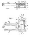
- Figs. 2 to 15 illustrate a compact portable liquid medication infusion device having a finger-type compact pump unit for infusion of liquid medication according to various embodiments of the present invention, in which Fig. 2 is a perspective view of the overall device with a cover case removed to show the internal structure;
- Fig. 3 is longitudinal section of the casing;
- Fig. 4 is a sectional view taken along line IV-IV of Fig. 3;
- Fig. 5 is a sectional view showing the support frame divided or split into upper and lower half sections;
- Fig. 6 is a plan view of the upper half frame section;
- Figs. 7, 8 and 9 are sectional views taken along lines VII-VII, VIII-VIII and IX-IX of Fig. 6;
- Fig. 10 is a bottom view of the lower support frame section.
- Figs. 11, 12 and 13 are sectional views taken along line XI-XI, XII-XII and XIII-XII of Fig. 9;
- Figs. 14 and 15 show different sequential steps in finger operation for describing the peristaltic finger movement of three fingers;
- Fig. 16 shows modified sequential steps in the finger operation of five fingers; and
- Fig. 17 is a sectional view showing the fingers carried by the support frame at a folding zone of markedly reduced thickness according to a modification of the present invention.
- Figs. 2, 3 and 4 show a small-sized portable medication infusion device suitably employed as an insulin injection device. The device includes a
casing 8 enclosing apump unit 9, apump control unit 10, a battery 11 and adisposable medication bag 12, and may be hermetically sealed by acover 13. The device is so constructed that, upon activation of a switch (not shown) to turn on the battery 11, different commands stored in memory are sent to thepump control unit 10 at predetermined time intervals so that thepump 9 operates to squeeze or collapse afeeding tube 14 repeatedly to dispense the medication from the medication bag into a catheter (not shown) inserted into the human body. - The
pump unit 9 may be controlled by any of a variety of control means including on/off switching devices for the power source, or automatic control means aided by microcomputers. - Referring now to the
pump unit 9, theunit 9 preferably is contained in a casing along with thepump control unit 10, but these components may also be contained in separate vessels. Thepump unit 9 need not be constructed to enclose thedisposable medication bag 12, it being only necessary that thefeeding tube 14 be sandwiched and collapsed or squeezed to effect infusion of the liquid medication. - The
pump unit 9 must have rotary drive means 15 such as a motor. An arrangement will suffice in which thefeeding tube 14 of themedication bag 12 is placed between acap 20 and fingers that are peristaltically moved by operation of acam 16 driven in turn by the rotary drive means 15. Thefeeding tube 14 is squeezed by the fingers to effect liquid infusion. The threefingers side fingers feeding tube 14 may be collapsed substantially by point engagement to reduce the force required to completely collapse the tube and, hence, to lighten the burden of the drive system. The inner orcentral finger 18 is of larger width so as to have a pumping capability to collapse thetube 14 over a required length, in order to afford an effective peristaltic liquid feeding function with the use of a minimum number of fingers so as to reduce the number of components and manufacturing steps. Thefingers shaped support frame 21 on which thefingers cap 20 and thecam 16 are mounted. As shown in Figs. 5 to 13, thesupport frame 21 is divided into upper frame sections 21 a facing thefingers 21 and tower frame sections 21 b facing the lower surface of acam 16, and is adapted to hold thecam 16 on either side bybearings 22, 23. These bearings are used to reduce power loss in the drive system. Thecam 16 is formed as one piece with a common axis. Thecam 16 hasend cam portions 16a, 16c of maximum radii which are smaller than the minimum radius of the axially central cam portion 16b, as shown in Fig. 3. With such a cam profile, the cam can be extracted from the mold in the axial direction when molded as one piece to reduce assembly error, so that loss of motive power due to friction with the fingers caused by burrs or like irregularities on the cam surface may be prevented. As shown in Figs. 6, 7 and 8, the upper frame sections 21a are formed integrally withfingers fingers plate spring portions 24. The purpose of such structure is to enhance machining and assembly precision through integral molding- and to free the fingers for the purpose of reducing power loss caused by friction with finger guides. Longitudinally extendingslits cap 20 are provided in the faces of the frame portion adjacent to thefingers slit 17 is provided in the upper surface of thecasing 8 facing thepump unit 9. The purpose of such structure is to stabilize thedisposable medication bag 12 by being linearly positioned in theslits cap 20 is pivotally mounted by a pin shaft 28 to one side of the support frame section 21a. The cap has ascrew 29 which may be engaged with or disengaged from a tappedhole 30 in the frame portion 21 a towards the finger root for opening or closing the cap. A flexible metal orplastic sheet 31 is mounted on the surface of thecap 20 facing the fingers, so as to be intimately contactable with thecentral finger 18, and is secured tocap 20 with a screw 32 or an adhesive at an end portion of thesheet 31 free from contact with thefeeding tube 14. Anadjustment screw 33 operable from the cap side of thesheet 31 is threadably mounted throughsheet 31 at the position contactable with feedingtube 14. The purpose of such structure is to adjust the gap by adjustment of thescrew 33 and, hence, to adjust the extent to which thefeeding tube 14 is squeezed, thereby regulating the flow of liquid medication. The preferred degree of adjustment is such as will not completely collapse the feedingtube 14, in order to provide smooth and durable restoration of the tube.Rubber segments 34, 35 are mounted on the same surface of thecap 20 and at positions registering with theside fingers tube 14, in order to provide smooth and durable tube restoration and to prevent the fracture of the feedingtube 14 if the feeding tube is crushed completely by theside fingers cam 16 is formed integrally ofend cam portions 16a, 16c slidably engaged withside fingers central finger 18 and asensing plate 16d having equiangular peripheral slits for sensing the number of motor revolutions. Adopting such an integral molding operation is useful in reducing the number of components and manufacturing steps and in increasing productivity and assembly accuracy.Cam portions 16a, 16b, 16c have different cam profiles of the desired shape, e.g. eccentric circles. Since the cam portion 16b has a minimum radius which is more than the maximum radius of thecam portions 16a, 16c, it is possible to extract the metallic mold axially of the cam so that the cam can be molded integrally without forming burrs on the cam surface, so that there little loss of driving power. The correlation of these cam profiles are selected so that thefingers 17 to 19 may be peristaltically displaced as shown in Fig. 14 or 15 for the tube squeezing process. Thecam 16,fingers support frame 21 are molded from highly wear- resistant plastic materials such as polyacetal, polyamid, polyethylene, polypropylene or fluorine resin, in order to prevent wear due to sliding contact between thecam 16 and thefingers fingers leaf spring portion 24 of the thin-walled finger root has a rectangular cross- section. The lower frame portion 21b has finger guides 36, 37, 38, 39 adapted to enter the gaps on both sides and between thefingers fingers cam portions 16a, 16b, 16c. - The finger guides of the present invention are not ordinarily in contact with the fingers, unlike the guides used in the conventional device, and may be used advantageously with a battery- driven injection device because no loss of driving power results from frictional contact with the guide during the finger operation.
- The rotary drive means 15 is a miniature coreless motor fitted with a reduction gear and clamped in position by an
upper mounting plate 40a and alower mounting plate 40b to facilitate the assembly operation. Theupper mounting plate 40a is formed integrally with the upper frame sections 21a while thelower mounting plate 40b is formed integrally with the lower frame sections 21 b. The purpose of such integral molding is to reduce the number of components, to enable the components to be manufactured with great accuracy and uniformity and to maintain assembly precision. Elongate slits 41, 42 are provided respectively in the connecting portion between theplate 40a and frame sections 21a and in the connecting portion between theplate 40a and frame sections 21 b for absorbing looseness or mounting error between themotor 15 and mountingplates coreless motor 15 has an output shaft 15a which intrudes into an axial bore in thecam 16 and is connected thereto by apin 43. A light emitter 44 and a light receiver 45 are mounted on both sides of and in opposition to the peripheral slits in thesensing plate 16d of thecam 16 for supplying thepump control unit 10 with feedback signals indicative of the number of revolutions of thecam 16. - In mounting the
pump unit 9 in thecasing 8, thecam 16 is fit on the lower frame sections 21b along with thebearings 22, 23 disposed on either side of thecam 16. With the neck of the output shaft 15a of themotor 15 placed on thelower mounting plate 40b, the output shaft 15a is inserted into the axial bore 16e of thecam 16, and thepin 43 is driven in place for connecting thecam 16 to themotor 15. Then, the upper frame sections 21a are placed on the lower frame sections 21 b and connected thereto by ascrew 47. Theupper mounting plate 40a is secured in place by ascrew 48. Thesupport frame 21 is placed onbase blocks casing 8 and is secured thereto by ascrew 46. Thecap 20 with built-ingap adjustment sheet 31,adjustment screw 33,screw 29 andrubber segments 34, 35 is pivotally mounted by pin shaft 28 on the upper frame portion 21a. According to the present invention, adjustment of thecam 16 andfingers - The operation of the
pump unit 9 will now be described in connection with the medication infusion device of the present invention. In using the device, adisposable bag 12 is placed in the casing, thecap 20 is opened, the feedingtube 14 is laid in theslits fingers cover casing 13 is closed. Then, as the power source is turned on,control unit 10 is driven into operation by power supplied by the battery. Thecontrol unit 10 has a memory, a clock for calling data from the memory and a motor driving circuit designed to rotate the motor a certain number of revolutions commensurate with the data obtained from the memory. The clock is active at all times and calls the specified memory locations after the lapse of a predetermined unit time such as one minute. The memory stores a program defining the infusion dose per minute determined beforehand and based upon the patient's meal time, ambulation and sleep or rest periods. Thus the memory issues the specified signal called by the clock. The motor drive circuit converts the signal into a form indicative of motor revolution and delivers the converted signal at one-minute intervals for driving themotor 15 of thepump unit 9 accordingly. In the present embodiment, the memory locations addressed are changed at intervals of 15 minutes. Thepump unit 9 then operates to squeeze thetube 14 repeatedly to dispense the medication in thebag 12 into the catheter inserted into the patient's body. - In operation of the
pump unit 9, when themotor 15 is driven into rotation, thecam 16 is rotated very slowly by operation of the reduction gear so that thefingers cam portions 16a, 16b, 16c, as shown in Fig. 14 or 15 to repeatedly squeeze the feedingtube 14 between them and thecap 20. Thus, upon squeezing action of thecentral finger 18, liquid medication is fed into the catheter in an amount corresponding to the squeezed tube volume. - The medication infusion device of the present invention having the finger-type pump unit is not limited to the above embodiment of the invention, but may be modified in a number of ways. Specifically, the finger-type pump unit to be employed in the present invention may be subjected to the following modifications:
- (a) The rotary drive means 15 is not limited to an electrical motor but may comprise other drive means such as a hand-wound, clock. When the
pump unit 9 is used for infusion of insulin, the use of an electric motor calls for the installation of speed reducing means because of the extremely small infusion doses involved. - (b) More than one
central finger 18 can be used. Thecentral finger 18 may have any specific width depending on the amount of liquid dispensed and the rotational speed as well as the number of revolutions of themotor 15. Rather than having a single central finger of a large width, however, the finger may be divided into two or three portions, and the number of cam discs on thecam 15 may be increased correspondingly for peristaltic operation of the fingers. - (c) The
cap 20 need not be designed to open pivotally as in the manner of a door, but may be fastened at four locations by means of screws. - (d) Two or more
central fingers 18 may be provided instead of one. In such case, the number of cam portions must be increased correspondingly. In using, for instance, five fingers, the fingers must be moved by a sequence as shown in the finger process diagram of Fig. 16 by suitable selection of the operative relation between the fingers and the cam portions. - (e) The
slits tube 14 stably in thesupport frame 21 are not always necessary. For example, in the embodiment shown in Fig. 2, theseslits slit 27 in thecasing 8 is sufficient to hold thetube 14 in stable fashion. Alternatively, suitable engaging means may be provided in thecasing 8 separately from thesupport frame 21, or on both sides of the casing when only thepump unit 9 is contained in the casing. - (f) The fingers and the support frame need not be molded but may be machined into a unitary body.
- (g) The mounting
plate 40 for the motor may be provided separately from thesupport frame 21. - (h) The
sensing plate 16d may be separately provided and assembled on thecam 16. - (i) The fingers and the support means may be integrally molded or machined from crystalline plastic material such as polyacetal, polyethylene, polypropylene or polyamide, and the cantilevered end parts of the fingers may be folding
parts 24a with the smallest possible thickness in the direction of the cap end cam. In this case, the camming operation results in finger movement about the folding parts as a center so that there is less driving power loss than when the plate spring portions are used. Also, the crystalline plastic material is durable and highly resistant to torsion and increases in strength with continued use because stress application in a constant direction results in an orderly rearrangement of the high polymer crystal lattice. - From the foregoing it is seen that the infusion device of the present invention comprises a finger-type pump unit in which a feeding tube is sandwiched between three or more fingers and the cap and squeezed thereby to dispense the medication, wherein both side fingers of lesser width and one or two or more inner or central fingers of greater width are supported by plate spring portions in cantilevered fashion so that the fingers are peristaltically displaced by a cam formed as a unitary body with a common axis. Thus the number of components and manufacturing steps may be markedly reduced over the prior-art infusion device having the conventional pump unit. Moreover, the finger guides in the pump unit may be omitted to improve durability and cut power consumption by eliminating frictionally engaging parts.
- According to a modification, when the support frame is divided into upper and lower frame sections encircling the fingers, cam assembly operation can be facilitated considerably. When the fingers and the support frame are molded integrally and the finger roots are reduced in thickness so as to be used as plate spring portions, the number of components in the device can be minimized and the dimensional and assembly precision improved to offset the higher costs entailed by metallic molds. If the fingers are oscillable by pins or connected by metallic plates to the support frame, then the metallic molds for the fingers and the frame can be simplified. Adjustment of the dispensed liquid dose is facilitated when the gap control sheet is affixed to the inner surface of the cap and flexed by the screw to provide an adjustable gap between it and the central finger. Finally, when mounting plates for rotary drive means such as motors are formed integrally with the support frame and the connecting portions are formed with slits, the number of components can be minimized with a facilitated assembly operation.
- Thus it is seen that merely adopting a small size version of the conventional pump unit as in the prior art increases the number of components and gives rise to accumulated fitting and assembly errors that may affect the precision of the pump structure and, hence of the infusion device containing the pump. In accordance with the present invention, however, pump fitting and assembly errors can be eliminated and the relative error ratio accompanying the reduction in size can be reduced to assure the desired pumping accuracy. The infusion device therefore exhibits improved infusion efficiency. In addition, the infusion device is durable because frictional pump components are eliminated. Owing to reduced power consumption, moreover, the battery lasts longer. This is an extremely important feature which makes the infusion device sufficiently portable.
Claims (11)
Applications Claiming Priority (2)
| Application Number | Priority Date | Filing Date | Title |
|---|---|---|---|
| JP56104819AJPS587253A (en) | 1981-07-04 | 1981-07-04 | Drug liquid pouring apparatus |
| JP104819/81 | 1981-07-04 |
Publications (2)
| Publication Number | Publication Date |
|---|---|
| EP0069350A1 EP0069350A1 (en) | 1983-01-12 |
| EP0069350B1true EP0069350B1 (en) | 1985-11-13 |
Family
ID=14391005
Family Applications (1)
| Application Number | Title | Priority Date | Filing Date |
|---|---|---|---|
| EP82105880AExpiredEP0069350B1 (en) | 1981-07-04 | 1982-07-01 | Medication infusion device |
Country Status (5)
| Country | Link |
|---|---|
| US (1) | US4479797A (en) |
| EP (1) | EP0069350B1 (en) |
| JP (1) | JPS587253A (en) |
| DE (2) | DE8218891U1 (en) |
| IT (1) | IT1151676B (en) |
Cited By (11)
| Publication number | Priority date | Publication date | Assignee | Title |
|---|---|---|---|---|
| US5935099A (en) | 1992-09-09 | 1999-08-10 | Sims Deltec, Inc. | Drug pump systems and methods |
| US7347836B2 (en) | 1992-09-09 | 2008-03-25 | Smiths Medical, Inc. | Drug pump systems and methods |
| US8133197B2 (en) | 2008-05-02 | 2012-03-13 | Smiths Medical Asd, Inc. | Display for pump |
| US8149131B2 (en) | 2006-08-03 | 2012-04-03 | Smiths Medical Asd, Inc. | Interface for medical infusion pump |
| US8250483B2 (en) | 2002-02-28 | 2012-08-21 | Smiths Medical Asd, Inc. | Programmable medical infusion pump displaying a banner |
| US8435206B2 (en) | 2006-08-03 | 2013-05-07 | Smiths Medical Asd, Inc. | Interface for medical infusion pump |
| US8504179B2 (en) | 2002-02-28 | 2013-08-06 | Smiths Medical Asd, Inc. | Programmable medical infusion pump |
| US8567235B2 (en) | 2010-06-29 | 2013-10-29 | Baxter International Inc. | Tube measurement technique using linear actuator and pressure sensor |
| US8858526B2 (en) | 2006-08-03 | 2014-10-14 | Smiths Medical Asd, Inc. | Interface for medical infusion pump |
| US8954336B2 (en) | 2004-02-23 | 2015-02-10 | Smiths Medical Asd, Inc. | Server for medical device |
| US8965707B2 (en) | 2006-08-03 | 2015-02-24 | Smiths Medical Asd, Inc. | Interface for medical infusion pump |
Families Citing this family (112)
| Publication number | Priority date | Publication date | Assignee | Title |
|---|---|---|---|---|
| US4653987A (en)* | 1984-07-06 | 1987-03-31 | Tsuyoshi Tsuji | Finger peristaltic infusion pump |
| US4650469A (en)* | 1984-10-19 | 1987-03-17 | Deltec Systems, Inc. | Drug delivery system |
| DE3581704D1 (en)* | 1984-10-19 | 1991-03-14 | Pharmacia Deltec Inc | MEDICINE DISPENSING SYSTEM. |
| JPS61228872A (en)* | 1985-04-01 | 1986-10-13 | シャープ株式会社 | Liquid drug injection apparatus |
| CH668295A5 (en)* | 1985-05-02 | 1988-12-15 | Doltron Ag | HOSE PUMP. |
| JPS6232968A (en)* | 1985-08-02 | 1987-02-12 | 日機装株式会社 | Infusion pump |
| US4617014A (en)* | 1985-11-26 | 1986-10-14 | Warner-Lambert Company | Dual mode I. V. infusion device |
| US4690673A (en)* | 1985-11-26 | 1987-09-01 | Imed Corporation | Dual mode I.V. infusion device with distal sensor |
| US4725205A (en)* | 1987-01-30 | 1988-02-16 | Fisher Scientific Group Inc. | Peristaltic pump with cam action compensator |
| US4728265A (en)* | 1987-01-30 | 1988-03-01 | Fisher Scientific Group Inc. | Peristaltic pump with cam action compensator |
| US4755109A (en)* | 1987-04-03 | 1988-07-05 | Fisher Scientific Company Inc. | Snap-together peristaltic mechanism |
| US4781548A (en)* | 1987-04-10 | 1988-11-01 | Alderson Richard K | Infusion pump system and conduit therefor |
| US4890984A (en)* | 1987-04-10 | 1990-01-02 | Alderson Richard K | Infusion pump system and conduit therefor |
| US4893991A (en)* | 1987-05-27 | 1990-01-16 | Heminway James F | Method and means for improving efficiency of peristaltic pumps |
| US4872813A (en)* | 1987-12-01 | 1989-10-10 | Pacesetter Infusion, Ltd. | Disposable cassette for a medication infusion system |
| US4818190A (en)* | 1987-12-01 | 1989-04-04 | Pacesetter Infusion, Ltd. | Cassette loading and latching apparatus for a medication infusion system |
| US4850817A (en)* | 1987-12-01 | 1989-07-25 | Pacesetter Infusion, Ltd. | Mechanical drive system for a medication infusion system |
| DE3741262A1 (en)* | 1987-12-05 | 1989-06-22 | Suttner Gmbh & Co Kg | HOSE PUMP |
| US5074756A (en)* | 1988-05-17 | 1991-12-24 | Patient Solutions, Inc. | Infusion device with disposable elements |
| US5246347A (en) | 1988-05-17 | 1993-09-21 | Patients Solutions, Inc. | Infusion device with disposable elements |
| US5803712A (en) | 1988-05-17 | 1998-09-08 | Patient Solutions, Inc. | Method of measuring an occlusion in an infusion device with disposable elements |
| US5131816A (en)* | 1988-07-08 | 1992-07-21 | I-Flow Corporation | Cartridge fed programmable ambulatory infusion pumps powered by DC electric motors |
| US4950245A (en)* | 1988-07-08 | 1990-08-21 | I-Flow Corporation | Multiple fluid cartridge and pump |
| US5011378A (en)* | 1988-07-08 | 1991-04-30 | I-Flow Corporation | Pump tube mount and cartridge for infusion pump |
| GB8825816D0 (en) | 1988-11-04 | 1988-12-07 | Danby Medical Eng Ltd | Pumping device |
| DE3912405C1 (en)* | 1989-04-15 | 1990-10-31 | B. Braun Melsungen Ag, 3508 Melsungen, De | |
| US4936760A (en)* | 1989-06-12 | 1990-06-26 | Williams David R | Volumetric infusion pump |
| US5165873A (en)* | 1989-10-10 | 1992-11-24 | Imed Corporation | Two-cycle peristaltic pump |
| US5055001A (en)* | 1990-03-15 | 1991-10-08 | Abbott Laboratories | Volumetric pump with spring-biased cracking valves |
| US5039279A (en)* | 1990-03-15 | 1991-08-13 | Abbott Laboratories | Sensor for detecting fluid flow from a positive displacement pump |
| US5158437A (en)* | 1990-03-15 | 1992-10-27 | Abbott Laboratories | Volumetric pump with spring-biased cracking valves |
| US5180287A (en)* | 1990-03-15 | 1993-01-19 | Abbott Laboratories | Method for monitoring fluid flow from a volumetric pump |
| US5357827A (en)* | 1990-03-15 | 1994-10-25 | Abbott Laboratories | Torque compensated cam assembly and method |
| US5078362A (en)* | 1990-03-15 | 1992-01-07 | Abbott Laboratories | Spring-biased valve for use in a positive displacement volumetic pump |
| US5116203A (en)* | 1990-03-15 | 1992-05-26 | Abbott Laboratories | Detecting occlusion of proximal or distal lines of an IV pump |
| AU7277391A (en)* | 1990-03-15 | 1991-09-19 | Abbott Laboratories | A spring-biased valve for use in a positive displacement volumetric pump |
| US5127908A (en)* | 1990-06-15 | 1992-07-07 | Sherwood Medical Company | Peristaltic infusion device |
| US5158528A (en)* | 1990-06-15 | 1992-10-27 | Sherwood Medical Company | Peristaltic infusion device and charger unit |
| US5181842A (en)* | 1990-06-15 | 1993-01-26 | Sherwood Medical Company | Peristaltic infusion device |
| US5133650A (en)* | 1990-06-15 | 1992-07-28 | Sherwood Medical Company | Infusion device rotor shield |
| US5057081A (en)* | 1990-06-15 | 1991-10-15 | Sherwood Medical Company | Peristaltic infusion device |
| US5147312A (en)* | 1990-06-15 | 1992-09-15 | Sherwood Medical Company | Peristaltic infusion device drip chamber yoke |
| USD348730S (en) | 1991-04-11 | 1994-07-12 | Sherwood Medical Company | Peristaltic infusion pump |
| USD342231S (en) | 1991-04-19 | 1993-12-14 | Sherwood Medical Company | Charger unit for a peristaltic infusion pump |
| US5217355A (en)* | 1991-08-05 | 1993-06-08 | Imed Corporation | Two-cycle peristaltic pump with occlusion detector |
| USD347472S (en) | 1991-09-23 | 1994-05-31 | Sherwood Medical Company | Combined peristaltic infusion pump and charger unit |
| CA2156827A1 (en)* | 1993-03-22 | 1994-09-29 | Robert Donald Grapes | A pump |
| US5482438A (en)* | 1994-03-09 | 1996-01-09 | Anderson; Robert L. | Magnetic detent and position detector for fluid pump motor |
| US5658133A (en)* | 1994-03-09 | 1997-08-19 | Baxter International Inc. | Pump chamber back pressure dissipation apparatus and method |
| US5630710A (en)* | 1994-03-09 | 1997-05-20 | Baxter International Inc. | Ambulatory infusion pump |
| US5549460A (en)* | 1994-08-08 | 1996-08-27 | Ivac Corporation | IV fluid delivery system |
| US5511951A (en)* | 1994-08-08 | 1996-04-30 | O'leary; Stephen H. | IV fluid delivery system |
| US5513957A (en)* | 1994-08-08 | 1996-05-07 | Ivac Corporation | IV fluid delivery system |
| US5499906A (en)* | 1994-08-08 | 1996-03-19 | Ivac Corporation | IV fluid delivery system |
| US5660529A (en)* | 1994-12-06 | 1997-08-26 | Mcgaw, Inc. | Linear peristaltic pump with reshaping fingers interdigitated with pumping elements |
| US6234773B1 (en) | 1994-12-06 | 2001-05-22 | B-Braun Medical, Inc. | Linear peristaltic pump with reshaping fingers interdigitated with pumping elements |
| CA2278239C (en) | 1997-01-17 | 2003-12-23 | Niagara Pump Corporation | Linear peristaltic pump |
| GR1002892B (en)* | 1997-02-17 | 1998-04-10 | Micrel | Linear peristaltic pump |
| US5964583A (en)* | 1997-10-15 | 1999-10-12 | Baxter International Inc. | Elastomerically assisted peristaltic pump |
| AU7839900A (en) | 1999-09-29 | 2001-04-30 | Sterling Medivations, Inc. | Reusable medication delivery device |
| US6485464B1 (en)* | 2000-04-28 | 2002-11-26 | Medtronic, Inc. | Reduced height implantable drug infusion device |
| JP4058498B2 (en) | 2001-02-23 | 2008-03-12 | ストライカー コーポレイション | Integrated drug delivery system |
| US20040034331A1 (en) | 2001-02-23 | 2004-02-19 | Jason Toman | Integrated medication delivery system |
| EP1436212B1 (en)* | 2001-09-20 | 2009-07-01 | Ben Z. Cohen | Microdispensing pump |
| US6942473B2 (en)* | 2002-03-21 | 2005-09-13 | Hospira, Inc. | Pump and tube set thereof |
| US20030181865A1 (en)* | 2002-03-21 | 2003-09-25 | Kent Abrahamson | Pump and tube set thereof |
| DE20210502U1 (en)* | 2002-07-06 | 2003-11-20 | B. Braun Melsungen Ag, 34212 Melsungen | Peristaltic peristaltic pump |
| US7527608B2 (en) | 2002-08-12 | 2009-05-05 | Lma North America, Inc. | Medication infusion and aspiration system and method |
| US8308457B2 (en) | 2004-11-24 | 2012-11-13 | Q-Core Medical Ltd. | Peristaltic infusion pump with locking mechanism |
| US8535025B2 (en) | 2006-11-13 | 2013-09-17 | Q-Core Medical Ltd. | Magnetically balanced finger-type peristaltic pump |
| IL179234A0 (en)* | 2006-11-13 | 2007-03-08 | Q Core Ltd | An anti-free flow mechanism |
| IL179231A0 (en)* | 2006-11-13 | 2007-03-08 | Q Core Ltd | A finger-type peristaltic pump comprising a ribbed anvil |
| JP5298699B2 (en)* | 2008-08-20 | 2013-09-25 | セイコーエプソン株式会社 | Control unit, tube unit, micro pump |
| JP5282508B2 (en) | 2008-09-29 | 2013-09-04 | セイコーエプソン株式会社 | Control unit, tube unit, micro pump |
| JP5195368B2 (en) | 2008-12-05 | 2013-05-08 | セイコーエプソン株式会社 | Tube unit, control unit, micro pump |
| US8371832B2 (en) | 2009-12-22 | 2013-02-12 | Q-Core Medical Ltd. | Peristaltic pump with linear flow control |
| US9677555B2 (en) | 2011-12-21 | 2017-06-13 | Deka Products Limited Partnership | System, method, and apparatus for infusing fluid |
| WO2013095459A1 (en)* | 2011-12-21 | 2013-06-27 | Deka Products Limited Partnership | System, method, and apparatus for electronic patient care |
| US20130071271A1 (en)* | 2010-03-17 | 2013-03-21 | David Rosen | Valveless pump |
| DE102010016106A1 (en)* | 2010-03-23 | 2011-09-29 | Andreas Hettich Gmbh & Co. Kg | Device for fluid supply and control of a fluidic system |
| KR101195821B1 (en) | 2010-05-06 | 2012-11-05 | 주식회사 우영메디칼 | Transfusion Device |
| US9457158B2 (en) | 2010-04-12 | 2016-10-04 | Q-Core Medical Ltd. | Air trap for intravenous pump |
| JP5614114B2 (en)* | 2010-06-09 | 2014-10-29 | セイコーエプソン株式会社 | Fluid transport device |
| US9179796B2 (en)* | 2010-09-22 | 2015-11-10 | Cornelia Bean Ltd. | Beverage making container for placement onto a cup |
| US9674811B2 (en) | 2011-01-16 | 2017-06-06 | Q-Core Medical Ltd. | Methods, apparatus and systems for medical device communication, control and localization |
| US9726167B2 (en) | 2011-06-27 | 2017-08-08 | Q-Core Medical Ltd. | Methods, circuits, devices, apparatuses, encasements and systems for identifying if a medical infusion system is decalibrated |
| DK2764245T3 (en)* | 2011-09-21 | 2018-01-29 | Sanofi Aventis Deutschland | PERISTAL PUMP AND PROCEDURE FOR TRANSPORTING MATERIALS WITH A PERISTAL PUMP |
| US9925034B2 (en)* | 2011-09-30 | 2018-03-27 | Verily Life Sciences Llc | Stabilizing unintentional muscle movements |
| US10368669B2 (en) | 2011-09-30 | 2019-08-06 | Verily Life Sciences Llc | System and method for stabilizing unintentional muscle movements |
| US9675756B2 (en) | 2011-12-21 | 2017-06-13 | Deka Products Limited Partnership | Apparatus for infusing fluid |
| US11295846B2 (en) | 2011-12-21 | 2022-04-05 | Deka Products Limited Partnership | System, method, and apparatus for infusing fluid |
| CA3111631C (en) | 2013-01-28 | 2022-12-13 | Smiths Medical Asd, Inc. | Medication safety devices and methods |
| US9855110B2 (en) | 2013-02-05 | 2018-01-02 | Q-Core Medical Ltd. | Methods, apparatus and systems for operating a medical device including an accelerometer |
| JP2014176440A (en)* | 2013-03-14 | 2014-09-25 | Aquatech Co Ltd | Chemical injection device |
| CN104234999B (en)* | 2013-06-08 | 2019-06-25 | 北京谊安医疗系统股份有限公司 | Camshaft and infusion pump with the camshaft |
| CN103334918B (en)* | 2013-07-09 | 2016-03-30 | 北京科力建元医疗科技有限公司 | For shifting fork piece device and the infusion pump of infusion pump |
| US10600596B2 (en) | 2014-04-21 | 2020-03-24 | Verily Life Sciences Llc | Adapter to attach implements to an actively controlled human tremor cancellation platform |
| EP3193975B1 (en) | 2014-09-18 | 2022-07-06 | DEKA Products Limited Partnership | Apparatus and method for infusing fluid through a tube by appropriately heating the tube |
| US10271770B2 (en) | 2015-02-20 | 2019-04-30 | Verily Life Sciences Llc | Measurement and collection of human tremors through a handheld tool |
| US9943430B2 (en) | 2015-03-25 | 2018-04-17 | Verily Life Sciences Llc | Handheld tool for leveling uncoordinated motion |
| CN104888307B (en)* | 2015-06-15 | 2018-06-19 | 中国人民解放军第三军医大学第三附属医院 | Portable intelligent infusion equipment |
| US10420663B2 (en) | 2017-05-01 | 2019-09-24 | Verily Life Sciences Llc | Handheld articulated user-assistive device with behavior control modes |
| JP7047185B2 (en) | 2018-08-16 | 2022-04-04 | デカ・プロダクツ・リミテッド・パートナーシップ | Medical pump |
| USD914197S1 (en) | 2018-08-16 | 2021-03-23 | Deka Products Limited Partnership | Syringe pump |
| USD918396S1 (en) | 2018-08-16 | 2021-05-04 | Deka Products Limited Partnership | Central controller |
| USD914195S1 (en) | 2018-08-16 | 2021-03-23 | Deka Products Limited Partnership | Syringe pump |
| USD914196S1 (en)* | 2018-08-16 | 2021-03-23 | Deka Products Limited Partnership | Peristaltic pump |
| ES2933693T3 (en) | 2019-11-18 | 2023-02-13 | Eitan Medical Ltd | Rapid test for medical pump |
| US11421672B2 (en)* | 2019-12-05 | 2022-08-23 | Hach Company | Linear peristaltic pump with pinch and compression block arrangement |
| US20220054742A1 (en)* | 2020-08-24 | 2022-02-24 | Modular Medical, Inc. | Portable infusion pump with pinch/squeeze pumping action |
| DK181469B1 (en)* | 2021-08-23 | 2024-02-20 | Lsm Pumper Aps | Linear peristaltic pump |
| CN114618027B (en)* | 2022-01-07 | 2025-07-04 | 浙江大学 | Automatic squeezing and flow rate monitoring device with chest tube |
Family Cites Families (12)
| Publication number | Priority date | Publication date | Assignee | Title |
|---|---|---|---|---|
| US2105200A (en)* | 1934-04-25 | 1938-01-11 | Hugh G Phelps | Surgical pump |
| US2625932A (en)* | 1949-01-10 | 1953-01-20 | Peter F Salisbury | Blood transfer apparatus |
| GB1287951A (en)* | 1969-06-12 | 1972-09-06 | ||
| US3679331A (en)* | 1970-04-24 | 1972-07-25 | Delta Scient Corp | Metering pump and valve |
| US3778195A (en)* | 1972-07-20 | 1973-12-11 | G Bamberg | Pump for parenteral injections and the like |
| JPS49122005A (en)* | 1973-03-30 | 1974-11-21 | ||
| US4199307A (en)* | 1977-07-05 | 1980-04-22 | Andros Incorporated | Medical infusion system |
| US4273121A (en)* | 1978-02-17 | 1981-06-16 | Andros Incorporated | Medical infusion system |
| ES234032Y (en)* | 1978-02-17 | 1979-01-01 | PUMPING DEVICE FOR INFUSIONS IN MEDICAL APPLICATIONS | |
| DE2820281A1 (en)* | 1978-05-10 | 1979-11-15 | Fresenius Chem Pharm Ind | HOSE PUMP WITH HIGH DOSING ACCURACY |
| US4236880A (en)* | 1979-03-09 | 1980-12-02 | Archibald Development Labs, Inc. | Nonpulsating IV pump and disposable pump chamber |
| JPS5669480A (en)* | 1979-11-09 | 1981-06-10 | Shinano Denki Kk | Tube pump |
- 1981
- 1981-07-04JPJP56104819Apatent/JPS587253A/enactiveGranted
- 1982
- 1982-06-16USUS06/388,919patent/US4479797A/ennot_activeExpired - Lifetime
- 1982-07-01DEDE19828218891Upatent/DE8218891U1/ennot_activeExpired
- 1982-07-01DEDE8282105880Tpatent/DE3267400D1/ennot_activeExpired
- 1982-07-01EPEP82105880Apatent/EP0069350B1/ennot_activeExpired
- 1982-07-02ITIT22228/82Apatent/IT1151676B/enactive
Cited By (13)
| Publication number | Priority date | Publication date | Assignee | Title |
|---|---|---|---|---|
| US7347836B2 (en) | 1992-09-09 | 2008-03-25 | Smiths Medical, Inc. | Drug pump systems and methods |
| US7654976B2 (en) | 1992-09-09 | 2010-02-02 | Smiths Medical Asd, Inc. | Drug pump systems and methods |
| US5935099A (en) | 1992-09-09 | 1999-08-10 | Sims Deltec, Inc. | Drug pump systems and methods |
| US8504179B2 (en) | 2002-02-28 | 2013-08-06 | Smiths Medical Asd, Inc. | Programmable medical infusion pump |
| US8250483B2 (en) | 2002-02-28 | 2012-08-21 | Smiths Medical Asd, Inc. | Programmable medical infusion pump displaying a banner |
| US8954336B2 (en) | 2004-02-23 | 2015-02-10 | Smiths Medical Asd, Inc. | Server for medical device |
| US8858526B2 (en) | 2006-08-03 | 2014-10-14 | Smiths Medical Asd, Inc. | Interface for medical infusion pump |
| US8435206B2 (en) | 2006-08-03 | 2013-05-07 | Smiths Medical Asd, Inc. | Interface for medical infusion pump |
| US8149131B2 (en) | 2006-08-03 | 2012-04-03 | Smiths Medical Asd, Inc. | Interface for medical infusion pump |
| US8952794B2 (en) | 2006-08-03 | 2015-02-10 | Smiths Medical Asd, Inc. | Interface for medical infusion pump |
| US8965707B2 (en) | 2006-08-03 | 2015-02-24 | Smiths Medical Asd, Inc. | Interface for medical infusion pump |
| US8133197B2 (en) | 2008-05-02 | 2012-03-13 | Smiths Medical Asd, Inc. | Display for pump |
| US8567235B2 (en) | 2010-06-29 | 2013-10-29 | Baxter International Inc. | Tube measurement technique using linear actuator and pressure sensor |
Also Published As
| Publication number | Publication date |
|---|---|
| JPS631858B2 (en) | 1988-01-14 |
| DE3267400D1 (en) | 1985-12-19 |
| DE8218891U1 (en) | 1982-12-16 |
| IT8222228A0 (en) | 1982-07-02 |
| JPS587253A (en) | 1983-01-17 |
| US4479797A (en) | 1984-10-30 |
| EP0069350A1 (en) | 1983-01-12 |
| IT1151676B (en) | 1986-12-24 |
Similar Documents
| Publication | Publication Date | Title |
|---|---|---|
| EP0069350B1 (en) | Medication infusion device | |
| US7534226B2 (en) | Dispensing fluid from an infusion pump system | |
| US8920144B2 (en) | Peristaltic pump with linear flow control | |
| CA2698027C (en) | Novel drive system for use with an insulin delivery device | |
| EP1933902B1 (en) | Infusion pump with a drive having a ratchet and pawl combination | |
| EP2198164B1 (en) | Drug delivery pump drive using linear piezoelectric motor | |
| US20090143730A1 (en) | Lead screw delivery device using reusable shape memory actuator device | |
| EP3909624A1 (en) | Drug delivery assembly for cartridge-based medicaments | |
| KR101404847B1 (en) | Pen type device for injecting medical fluid | |
| KR101404823B1 (en) | Apparatus for supplying medicinal fluid | |
| CN219001462U (en) | Detachable insulin pump | |
| JPH0236519Y2 (en) | ||
| ITTO990393A1 (en) | APPARATUS FOR PROLONGED INFUSION OF DRUGS | |
| HK1148233B (en) | Novel drive system for use with an insulin delivery device |
Legal Events
| Date | Code | Title | Description |
|---|---|---|---|
| PUAI | Public reference made under article 153(3) epc to a published international application that has entered the european phase | Free format text:ORIGINAL CODE: 0009012 | |
| AK | Designated contracting states | Designated state(s):DE FR GB NL | |
| 17P | Request for examination filed | Effective date:19830704 | |
| GRAA | (expected) grant | Free format text:ORIGINAL CODE: 0009210 | |
| RAP1 | Party data changed (applicant data changed or rights of an application transferred) | Owner name:TERUMO KABUSHIKI KAISHA TRADING AS TERUMO CORPORAT | |
| AK | Designated contracting states | Designated state(s):DE FR GB NL | |
| REF | Corresponds to: | Ref document number:3267400 Country of ref document:DE Date of ref document:19851219 | |
| ET | Fr: translation filed | ||
| PLBE | No opposition filed within time limit | Free format text:ORIGINAL CODE: 0009261 | |
| STAA | Information on the status of an ep patent application or granted ep patent | Free format text:STATUS: NO OPPOSITION FILED WITHIN TIME LIMIT | |
| 26N | No opposition filed | ||
| PGFP | Annual fee paid to national office [announced via postgrant information from national office to epo] | Ref country code:DE Payment date:20010625 Year of fee payment:20 | |
| PGFP | Annual fee paid to national office [announced via postgrant information from national office to epo] | Ref country code:GB Payment date:20010627 Year of fee payment:20 | |
| PGFP | Annual fee paid to national office [announced via postgrant information from national office to epo] | Ref country code:FR Payment date:20010712 Year of fee payment:20 | |
| PGFP | Annual fee paid to national office [announced via postgrant information from national office to epo] | Ref country code:NL Payment date:20010730 Year of fee payment:20 | |
| REG | Reference to a national code | Ref country code:GB Ref legal event code:IF02 | |
| PG25 | Lapsed in a contracting state [announced via postgrant information from national office to epo] | Ref country code:GB Free format text:LAPSE BECAUSE OF EXPIRATION OF PROTECTION Effective date:20020630 | |
| PG25 | Lapsed in a contracting state [announced via postgrant information from national office to epo] | Ref country code:NL Free format text:LAPSE BECAUSE OF EXPIRATION OF PROTECTION Effective date:20020701 | |
| REG | Reference to a national code | Ref country code:GB Ref legal event code:PE20 Effective date:20020630 | |
| NLV7 | Nl: ceased due to reaching the maximum lifetime of a patent | Effective date:20020701 |