EP0068269B1 - Hinge structure for a sun visor or the like - Google Patents
Hinge structure for a sun visor or the likeDownload PDFInfo
- Publication number
- EP0068269B1 EP0068269B1EP82105198AEP82105198AEP0068269B1EP 0068269 B1EP0068269 B1EP 0068269B1EP 82105198 AEP82105198 AEP 82105198AEP 82105198 AEP82105198 AEP 82105198AEP 0068269 B1EP0068269 B1EP 0068269B1
- Authority
- EP
- European Patent Office
- Prior art keywords
- shaft
- envelope
- leaf spring
- flat surfaces
- flat
- Prior art date
- Legal status (The legal status is an assumption and is not a legal conclusion. Google has not performed a legal analysis and makes no representation as to the accuracy of the status listed.)
- Expired
Links
Images


Classifications
- B—PERFORMING OPERATIONS; TRANSPORTING
- B60—VEHICLES IN GENERAL
- B60J—WINDOWS, WINDSCREENS, NON-FIXED ROOFS, DOORS, OR SIMILAR DEVICES FOR VEHICLES; REMOVABLE EXTERNAL PROTECTIVE COVERINGS SPECIALLY ADAPTED FOR VEHICLES
- B60J3/00—Antiglare equipment associated with windows or windscreens; Sun visors for vehicles
- B60J3/02—Antiglare equipment associated with windows or windscreens; Sun visors for vehicles adjustable in position
- B60J3/0204—Sun visors
- B60J3/0213—Sun visors characterised by the mounting means
- B60J3/0265—Attachments of sun visors to mounting means including details of sun visor bearing member regulating the rotational friction on the support arm
- B—PERFORMING OPERATIONS; TRANSPORTING
- B60—VEHICLES IN GENERAL
- B60J—WINDOWS, WINDSCREENS, NON-FIXED ROOFS, DOORS, OR SIMILAR DEVICES FOR VEHICLES; REMOVABLE EXTERNAL PROTECTIVE COVERINGS SPECIALLY ADAPTED FOR VEHICLES
- B60J3/00—Antiglare equipment associated with windows or windscreens; Sun visors for vehicles
- B60J3/02—Antiglare equipment associated with windows or windscreens; Sun visors for vehicles adjustable in position
- B60J3/0204—Sun visors
- B60J3/0213—Sun visors characterised by the mounting means
- B60J3/0252—Structure of the support arm
Definitions
- the present inventionrelates according to the precharacterising part of claim 1 to a hinge structure for a sun visor for an automotive vehicle or the like which is known from GB-A-1452220.
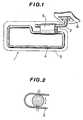
- a sun visor 1has been hingedly mounted on the ceiling 6 of a vehicle cabin via an angled shaft 2 and a springy envelope 3 which engages the surface of the shaft 2.
- Fixedly connected to the springy envelope 3is a wire frame 4 on which the padding and cover 5 (shown in phantom) are disposed.
- this arrangementmay be set in any given desired position so as to adequately block out the rays of the sun while not excessively obscuring the driver's view.
- this arrangementparticularly after prolonged use has suffered from the drawback of moving from the selected position under the influence of vehicle vibration and the like.
- this arrangementcomprises a shaft 7 having flats 8 formed on either side thereof, an envelope 9 which is adapted to slidably receive the shaft 7 therein and which is disposed about the shaft, and a leaf spring 10 which is adapted to seat on top of the envelope 9 and engage the shaft 7 through apertures 11 formed in either side of the envelope.
- the leaf springis secured in place by a clip 12 which fits up around the bottom of the envelope and which includes apertures 13 t o to which barb-like extensions 14 extending from the leaf spring, engage.
- This "one sided bulging" actiontends to produce a force which acts about a fulcrum point located in the region of the parallel leg portions 19 of the leaf spring and generates a moment which tends to force the leaf spring to a position eccentric with respect to the envelope. Further, as only one flat is inducing a “bulging” of the leaf spring the resulting force forcing the surface of the leaf spring clip and shaft into friction generating contact is diminished as compared with the dual flat arrangement.
- the present inventionfeatures a hinge structure for a sun visor or like member supported on a shaft, wherein the shaft which pivotally supports the visor is formed with flat surfaces at longitudinally staggered positions and on opposite sides of the shaft, and a spring attached to the visor proper which has flat portions for engaging the flat surfaces.
- an envelope 20is formed with an essentially circular cross-section portion 22 adapted to rotatably receive an angled shaft 24 therein.
- the envelopehas a wire frame 26 fixed thereto for mounting a decorative padding and cover (not shown).
- the envelope 20is further formed with an aperture 28 into which a leaf spring 30 is inserted.
- the leaf spring 30is secured in position on the envelope by a second clip 32 which fits up around the lower edge of the envelope 20 and which is provided with apertures 34 which receive barb-like projections 36 formed on the spring clip.
- the shaft 24is formed with flat surfaces or flats 38 on either side thereof but at staggered positions therealong.
- the leaf spring 30is formed so as to have two flat portions 40 adapted to engage the flats on the shaft.
- Figs. 9A and 9Bthe envelope may be rotated through 360 degrees before the flat portions of the leaf spring will re-engage with their respective flat surface and thus no "snap action" occurs other than into the home position of the visor (viz., the position illustrated in Figs. 9A, 9B).
- the spring clipis "bulged out” on both sides, thus offsetting any tendency for the clip to produce the shuddering or jerky action encountered with the prior art.
Landscapes
- Engineering & Computer Science (AREA)
- Mechanical Engineering (AREA)
- Pivots And Pivotal Connections (AREA)
Description
- The present invention relates according to the precharacterising part of claim 1 to a hinge structure for a sun visor for an automotive vehicle or the like which is known from GB-A-1452220.
- In a previously proposed arrangement such as shown in Figs. 1 and 2 of the drawings, a sun visor 1 has been hingedly mounted on the ceiling 6 of a vehicle cabin via an
angled shaft 2 and aspringy envelope 3 which engages the surface of theshaft 2. Fixedly connected to thespringy envelope 3 is awire frame 4 on which the padding and cover 5 (shown in phantom) are disposed. In operation this arrangement may be set in any given desired position so as to adequately block out the rays of the sun while not excessively obscuring the driver's view. However, this arrangement, particularly after prolonged use has suffered from the drawback of moving from the selected position under the influence of vehicle vibration and the like. This has been particularly prevalent when the visor is set in a non-use or "storage" position wherein it abuts the ceiling 6 of the vehicle cabin. Hence, the driver and/or passengers of the vehicle have been plagued with the constant need to manually move the visor back to its storage position, sometimes with annoying frequency. - To overcome this problem it has been subsequently proposed to provide a hinge arrangement having a "snap action" which securely holds the visor in either one of two diametrically opposed positions. This arrangement is shown in Figs. 3, 4 and 5A-5C; As best seen in the exploded view of Fig. 4, this arrangement comprises a
shaft 7 havingflats 8 formed on either side thereof, an envelope 9 which is adapted to slidably receive theshaft 7 therein and which is disposed about the shaft, and aleaf spring 10 which is adapted to seat on top of the envelope 9 and engage theshaft 7 throughapertures 11 formed in either side of the envelope. The leaf spring is secured in place by aclip 12 which fits up around the bottom of the envelope and which includes apertures 13 toto which barb-like extensions 14 extending from the leaf spring, engage. - However, this arrangement has suffered from a drawback in that, as will be understood from Figs. 5A to 5C, as the envelope 9 is rotated about the
shaft 7 from a position such as that shown in Fig. 5A to one shown in Fig. 5B, the force of theleaf spring 10 tends, due to the presence of the twoflats 8, to automatically force the envelope 9 to continue to rotate until the position illustrated in Fig. 5C is reached. Thus, while the arrangement has served adequately to retain the visor in the storage position without trouble, once the visor is rotated toward thewindshield 15 of the vehicle to the degree of entering the range indicated by the arrow "a" in Fig. 3, then irrespective the operators wish, the visor will snap to a position diametrically opposite that of the storage one. This is of course undesirable as the driver (or passenger) may require an orientation which falls within the aforementioned range but wherein the snap action will tend to be induced. - To solve this, it has been proposed to provide only a
single flat 16 on the shaft and asingle surface 17 on theleaf spring 18 for engaging the flat (See Figs. 6A-6C)). Now, while this has provided only a single zone in which a desirable "snap" toward and into the storage position is provided, the arrangement has suffered from very jerky rotation of the visor from the storage position and tended to lack sufficient position maintaining ability. The reason for the jerky rotation is due to the existence of only one flat on the shaft and the resulting "bulging out" of only one side of the leaf spring 18 (as occurs as the envelope is rotated from the position shown in Fig. 6C to that in Fig. 6B. This "one sided bulging" action tends to produce a force which acts about a fulcrum point located in the region of theparallel leg portions 19 of the leaf spring and generates a moment which tends to force the leaf spring to a position eccentric with respect to the envelope. Further, as only one flat is inducing a "bulging" of the leaf spring the resulting force forcing the surface of the leaf spring clip and shaft into friction generating contact is diminished as compared with the dual flat arrangement. - The present invention features a hinge structure for a sun visor or like member supported on a shaft, wherein the shaft which pivotally supports the visor is formed with flat surfaces at longitudinally staggered positions and on opposite sides of the shaft, and a spring attached to the visor proper which has flat portions for engaging the flat surfaces. With this arrangement a "snap action" is provided only when the visor is rotated into close proximity of the home or storage position, wherein the flat portions of the spring clamp down flatly on the flat surfaces. When the visor is rotated away from this home position the distortion of the flat portions of the spring produces a reaction which induces sufficient friction between the shaft and the spring to hold the visor in any given selected position.
- The features and advantages of the arrangement of the present invention will become more clearly appreciated from the following description taken in conjunction with the accompanying drawings in which:
- Fig. 1 is a perspective view of a prior art arrangement;
- Fig. 2 is a sectional view of a portion of the shaft and envelope shown in Fig. 1;
- Fig. 3 is a schematic sectional view of a vehicle cabin showing the disposition of a prior art sun visor;
- Fig. 4 is an exploded perspective view of a part of the prior art arrangement shown in Fig. 3;
- Figs. 5A to 5C are sectional views showing the snap action produced in the arrangement of Figs. 3 and 4;
- Figs. 6A to 6C are sectional views showing the snap action produced by the prior art arrangement wherein the shaft is provided with only a single flat;
- Fig. 7 is an exploded perspective view of a preferred embodiment of the present invention;
- Fig. 8 is an elevation of the arrangement shown in Fig. 7;
- Figs. 9A and 9B are sections taken along section lines A-A and B-B of Fig. 8 respectively; and
- Fig. 10 is a section showing the leaf spring of the preferred embodiment when the visor is rotated to an operative position.
- Turning now to Figs. 7 to 10, a preferred embodiment of the present invention is shown. In this arrangement an
envelope 20 is formed with an essentiallycircular cross-section portion 22 adapted to rotatably receive anangled shaft 24 therein. The envelope has awire frame 26 fixed thereto for mounting a decorative padding and cover (not shown). Theenvelope 20 is further formed with anaperture 28 into which aleaf spring 30 is inserted. Theleaf spring 30 is secured in position on the envelope by asecond clip 32 which fits up around the lower edge of theenvelope 20 and which is provided withapertures 34 which receive barb-like projections 36 formed on the spring clip. - As shown the
shaft 24 is formed with flat surfaces orflats 38 on either side thereof but at staggered positions therealong. Theleaf spring 30 is formed so as to have twoflat portions 40 adapted to engage the flats on the shaft. - With this arrangement, when the envelope is -rotated to a position such as shown in Figs. 9A and 9B, wherein the
flat portions 40 of the leaf spring seat flatly on theflat surfaces 38 the envelope is held up against the ceiling without fear of unwantedly dropping down to obscure the driver's or passengers view. However, once the visor is manually moved from the just mentioned home position, the flat portions of the leaf spring are distorted or "bulged out" from the positions indicated in phantom in Fig. 10, and as both of the flat surfaces are distorted, a reaction is produced which biases the cylindrical surfaces of the shaft against the inner periphery of the leaf spring and as the flat surfaces are staggered along the shaft, the actual surface area of the shaft which is contacted by the distorted spring. is increased notably greater than the prior art, whereby the amount of friction which resists rotation of the spring (and therefore the envelope) about the shaft is increased markedly. - It will be appreciated from Figs. 9A and 9B that the envelope may be rotated through 360 degrees before the flat portions of the leaf spring will re-engage with their respective flat surface and thus no "snap action" occurs other than into the home position of the visor (viz., the position illustrated in Figs. 9A, 9B).
- Further, as the shaft is provided with two flat surfaces, the spring clip is "bulged out" on both sides, thus offsetting any tendency for the clip to produce the shuddering or jerky action encountered with the prior art.
Claims (4)
1. A hinge comprising:
a shaft (24);
a member rotatably supported on said shaft;
means defining first and second flat surfaces 38 on said shaft, said first and second flat surfaces being formed on opposite sides of said shaft; and
spring means (30) connected to said member for engaging said shaft and for resisting rotation of said member about said shaft, said spring means having resilient first and second flat portions 40 for engaging said first and second flat surfaces, respectively, when said member assumes a predetermined angular position with respect to said shaft, characterised in that said flat surfaces (38) on said shaft (24) and said flat portions (40) on said springs means (30) are arranged at longitudinally staggered positions.
2. A hinge as claimed in claim 1, wherein said member takes the form of an envelope (20) formed which has an essentially circular cross section portion (22) for rotatably receiving said shaft (24) and which has a wire frame (26) fixed thereto.
3. A hinge as claimed in claim 2, wherein said spring means takes the form of a leaf spring (30) which is clipped onto said envelope by a clip (32).
4. A hinge as claimed in claim 3 wherein said leaf spring is formed with barb-like extensions (36) and said clip is formed with apertures (34) for receiving said barb-like extensions therein.
Applications Claiming Priority (2)
| Application Number | Priority Date | Filing Date | Title |
|---|---|---|---|
| JP90579/81U | 1981-06-19 | ||
| JP9057981 | 1981-06-19 |
Publications (2)
| Publication Number | Publication Date |
|---|---|
| EP0068269A1 EP0068269A1 (en) | 1983-01-05 |
| EP0068269B1true EP0068269B1 (en) | 1985-01-16 |
Family
ID=14002339
Family Applications (1)
| Application Number | Title | Priority Date | Filing Date |
|---|---|---|---|
| EP82105198AExpiredEP0068269B1 (en) | 1981-06-19 | 1982-06-14 | Hinge structure for a sun visor or the like |
Country Status (4)
| Country | Link |
|---|---|
| US (1) | US4617699A (en) |
| EP (1) | EP0068269B1 (en) |
| AU (1) | AU526773B2 (en) |
| DE (1) | DE3261939D1 (en) |
Families Citing this family (89)
| Publication number | Priority date | Publication date | Assignee | Title |
|---|---|---|---|---|
| DE3134400A1 (en)* | 1981-08-31 | 1983-04-14 | Autopart Sweden GmbH, 8000 München | SUN VISOR FOR MOTOR VEHICLES OR THE LIKE. |
| DE8208831U1 (en)* | 1982-03-27 | 1982-07-22 | Fa. A. Raymond, 7850 Lörrach | BEARING FOR SUN VISOR BODY |
| US4610443A (en)* | 1983-12-13 | 1986-09-09 | Gebr. Happich Gmbh | Sun visor and method for the manufacture thereof |
| DE3345764C1 (en)* | 1983-12-17 | 1985-06-20 | Daimler-Benz Ag, 7000 Stuttgart | Sun visor for vehicles |
| DE3440976A1 (en)* | 1984-11-09 | 1986-05-15 | Gebr. Happich Gmbh, 5600 Wuppertal | SUN VISOR FOR VEHICLES |
| US4620742A (en)* | 1984-11-21 | 1986-11-04 | Irvin Industries Inc. | Visor detent |
| DE3601761C1 (en)* | 1986-01-22 | 1987-04-30 | Happich Gmbh Gebr | Sun visor for vehicles |
| US5080420A (en)* | 1986-05-23 | 1992-01-14 | Prince Corporation | Visor |
| US4925232A (en)* | 1986-05-23 | 1990-05-15 | Prince Corporation | Visor |
| US4783111A (en)* | 1986-05-23 | 1988-11-08 | Prince Corporation | Visor |
| JPH057629Y2 (en)* | 1986-08-29 | 1993-02-25 | ||
| SE462271B (en)* | 1986-10-06 | 1990-05-28 | Autopart Sweden Ab | SUN PROTECTION FOR MOTOR VEHICLE |
| ES1011244Y (en)* | 1987-02-27 | 1990-08-16 | Gabas Cebollero Carlos | SPRING MECHANISM FOR AUTOMOBILE VEHICLE PARASOLES HINGES |
| US4821374A (en)* | 1987-03-26 | 1989-04-18 | Irvin Industries, Inc. | Hinge assembly for vehicle visor and other vehicle accessories |
| US4785500A (en)* | 1987-06-15 | 1988-11-22 | Irvin Industries, Inc. | Hinge assembly for vehicle accessories |
| USD305298S (en) | 1987-07-01 | 1990-01-02 | De Langie Alan J | Visor hinge |
| US4828313A (en)* | 1987-11-02 | 1989-05-09 | Prince Corporation | Visor control |
| FR2628797B1 (en)* | 1988-03-17 | 1990-08-24 | Rockwell Cim | SUPPORT FOR ATTACHING OBJECTS TO COMPONENTS OF THE AUTOMOBILE, IN PARTICULAR FOR ATTACHING ICE TO A SUN VISOR IN FOAMED PLASTIC MATERIAL |
| US4840428A (en)* | 1988-06-24 | 1989-06-20 | Tachi-S Co., Ltd. | Head rest adjusting device |
| US5004288A (en)* | 1988-12-19 | 1991-04-02 | Gebr. Happich Gmbh | Sun visor for motor vehicle having a slidable main body |
| IT1232741B (en)* | 1989-05-19 | 1992-03-04 | Simaplast Srl | IMPROVEMENT RELATING TO THE VEHICLE OF SUPPORT OF THE LENSES OF MOTOR VEHICLES IN GENERAL |
| US5039153A (en)* | 1989-08-28 | 1991-08-13 | Prince Corporation | Pivot down vanity mirror assembly |
| US5004289A (en)* | 1989-09-27 | 1991-04-02 | Prince Corporation | Visor torque control |
| DE3939539A1 (en)* | 1989-11-30 | 1991-06-06 | Happich Gmbh Gebr | Vehicle sun visor spring - has body surrounding mounting pin and tongue, held by body and engaging flat on pin |
| ES2027930A6 (en)* | 1991-02-15 | 1992-06-16 | Ind Techno Matic Sa | Fixing spring for hinges of sun visors of motor vehicles. |
| US5139303A (en)* | 1991-07-16 | 1992-08-18 | Plasta Fiber Industries, Inc. | Sunvisor spring clip and attachment mechanism |
| ES2061357B1 (en)* | 1992-06-09 | 1996-11-16 | Ind Techno Matic Sa | SPRING-HINGE FOR PARASOL VISORS OF AUTOMOBILE VEHICLES. |
| DE4226252A1 (en)* | 1992-08-08 | 1994-02-10 | Happich Gmbh Gebr | Sun visors for vehicles |
| US5251949A (en)* | 1992-08-18 | 1993-10-12 | Plasta Fiber Industries, Inc. | Visor mounting system |
| KR940008935A (en)* | 1992-10-08 | 1994-05-16 | 이종득 | Automotive Multipurpose Sunshade |
| US5338083A (en)* | 1993-01-26 | 1994-08-16 | Plasta Fiber Industries Corp. | Visor detent spring clip |
| US5419604A (en)* | 1993-07-15 | 1995-05-30 | Clark; Brant V. | Pivotal visor/windshield for vessels |
| US5406678A (en)* | 1993-07-22 | 1995-04-18 | General Clutch Corporation | Friction hinge |
| AU8129294A (en)* | 1993-11-24 | 1995-06-13 | General Clutch Corporation | Friction hinge with detent |
| US5557828A (en)* | 1995-07-06 | 1996-09-24 | Eaton Corporation | Load center door hinge element |
| US5871252A (en)* | 1996-07-30 | 1999-02-16 | Lear Corporation | Telescopic sunvisor |
| FR2754217B1 (en)* | 1996-10-04 | 1998-12-24 | Rockwell Lvs France | TWO-PART ELBOWED SUPPORT ARM FOR SUN VISOR |
| US5967587A (en)* | 1997-03-18 | 1999-10-19 | Prince Corporation | Sliding visor |
| US5918348A (en)* | 1997-04-04 | 1999-07-06 | Torqmaster, Inc. | Friction hinge with detent capability |
| US5967588A (en)* | 1997-04-11 | 1999-10-19 | Prince Corporation | Visor control |
| US6120084A (en)* | 1997-10-02 | 2000-09-19 | Irvin Automotive Products, Inc. | Coated pivot pin/detent assembly |
| US5933917A (en)* | 1998-01-06 | 1999-08-10 | Delta Electronics Inc. | Case with adjustable and positionable handle device |
| US6174019B1 (en) | 1998-02-26 | 2001-01-16 | Prince Corporation | Extruded visor control |
| US6035491A (en)* | 1998-05-04 | 2000-03-14 | Hartigan; Michael J. | Hinge control mechanism for a foldable device |
| GB2337790B (en)* | 1998-05-29 | 2002-12-31 | Nokia Mobile Phones Ltd | Hinge mechanism |
| US6042172A (en)* | 1998-06-18 | 2000-03-28 | Lear Automotive Dearborn, Inc. | Torque control member for a visor assembly |
| DE19857454A1 (en)* | 1998-12-12 | 2000-08-10 | Johnson Contr Interiors Gmbh | Sun visors for vehicles |
| US6230365B1 (en)* | 2000-01-11 | 2001-05-15 | Lu Sheng-Nan | Hinge for a notebook computer |
| US6470532B2 (en) | 2000-02-29 | 2002-10-29 | Torqmaster, Inc. | Cam hinge with controlled friction for improved cam operation |
| US6296293B1 (en)* | 2000-04-28 | 2001-10-02 | Lear Corporation | Slidable auxiliary sun visor assembly |
| US6604798B1 (en) | 2000-08-10 | 2003-08-12 | Integra Enclosures | Enclosure for securing components |
| US6469247B1 (en) | 2000-11-16 | 2002-10-22 | Robroy Industries, Inc. | Enclosure |
| TW508040U (en)* | 2001-09-05 | 2002-10-21 | Hinge Basestrong Co Ltd | Radial pressing structure of rotation shaft |
| KR100446902B1 (en)* | 2001-12-27 | 2004-09-04 | 엘지전자 주식회사 | The hinge structure of plane-type display device |
| JP2004098748A (en)* | 2002-09-05 | 2004-04-02 | Honda Motor Co Ltd | Sun visor for vehicles |
| DE10306733B4 (en)* | 2003-02-17 | 2005-08-18 | Johnson Controls Interiors Gmbh & Co. Kg | Device for locking, body and arrangement |
| US7025400B2 (en)* | 2004-02-12 | 2006-04-11 | Irvin Automotive Products, Inc. | Visor nail |
| US20060267369A1 (en)* | 2005-05-13 | 2006-11-30 | Lear Corporation | Sun visor detent spring clip |
| TW200833934A (en)* | 2007-02-06 | 2008-08-16 | Mitac Technology Corp | Structure of pressing-type support rack of hinge |
| TW200833935A (en)* | 2007-02-06 | 2008-08-16 | Mitac Technology Corp | Engaging type socket structure of hinge |
| US20090179128A1 (en)* | 2008-01-14 | 2009-07-16 | Imation Corp. | Low-profile flat panel display mount |
| CN101677499B (en)* | 2008-09-17 | 2011-12-21 | 鸿富锦精密工业(深圳)有限公司 | Electronic device and hinge structure thereof |
| CN201297338Y (en)* | 2008-11-06 | 2009-08-26 | 康准电子科技(昆山)有限公司 | Pivot device |
| US8556325B2 (en) | 2011-09-20 | 2013-10-15 | Irvin Automotive Products, Inc. | Sliding visor |
| DE102013209797A1 (en)* | 2012-05-30 | 2013-12-05 | Kyowa Sangyo Co., Ltd. | SUNSHADE FOR A VEHICLE |
| JP5885628B2 (en)* | 2012-09-21 | 2016-03-15 | 河西工業株式会社 | Vehicle sun visor |
| US8914946B2 (en)* | 2013-05-20 | 2014-12-23 | First Dome Corporation | Dual-shaft pivot device |
| KR101298230B1 (en) | 2013-05-28 | 2013-08-22 | 유인규 | The door hinge apparatus for a furniture |
| US9625954B2 (en) | 2014-11-26 | 2017-04-18 | Microsoft Technology Licensing, Llc | Multi-pivot hinge |
| US10737559B2 (en) | 2014-12-16 | 2020-08-11 | Irvin Automotive Products, LLC | Visor |
| US10174534B2 (en) | 2015-01-27 | 2019-01-08 | Microsoft Technology Licensing, Llc | Multi-pivot hinge |
| US10162389B2 (en) | 2015-09-25 | 2018-12-25 | Microsoft Technology Licensing, Llc | Covered multi-axis hinge |
| US10227808B2 (en) | 2015-11-20 | 2019-03-12 | Microsoft Technology Licensing, Llc | Hinged device |
| EP3189995B1 (en)* | 2015-12-16 | 2019-11-13 | Motus Integrated Technologies | Slide-on-rod assembly for a vehicle sun visor |
| US10474203B2 (en) | 2016-09-01 | 2019-11-12 | Microsoft Technology Licensing, Llc | Hinged device |
| US10364598B2 (en) | 2016-09-02 | 2019-07-30 | Microsoft Technology Licensing, Llc | Hinged device |
| US10437293B2 (en) | 2016-09-23 | 2019-10-08 | Microsoft Technology Licensing, Llc | Multi-axis hinge |
| US10081228B2 (en)* | 2016-11-08 | 2018-09-25 | Mahmoud Razzaghi | Car visor |
| US10641318B2 (en) | 2016-12-09 | 2020-05-05 | Microsoft Technology Licensing, Llc | Hinged device |
| US10241548B2 (en) | 2016-12-09 | 2019-03-26 | Microsoft Technology Licensing, Llc | Computing device employing a self-spacing hinge assembly |
| US10253804B2 (en) | 2017-01-24 | 2019-04-09 | Microsoft Technology Licensing, Llc | Hinged device |
| US10296044B2 (en) | 2017-06-08 | 2019-05-21 | Microsoft Technology Licensing, Llc | Hinged device |
| US10344510B2 (en) | 2017-06-16 | 2019-07-09 | Microsoft Technology Licensing, Llc | Hinged device |
| US10688850B2 (en) | 2018-03-13 | 2020-06-23 | Irvin Automotive Products, LLC | Sliding visor |
| KR102055503B1 (en)* | 2018-06-14 | 2019-12-12 | 주식회사 동원테크 | Sunvisors for automobiles |
| TWI657017B (en)* | 2018-09-21 | 2019-04-21 | 美律實業股份有限公司 | Pivoting assembly and container including thereof |
| US10864804B2 (en) | 2019-02-28 | 2020-12-15 | Irvin Automotive Products, LLC | Sliding thin visor |
| US10870337B2 (en) | 2019-02-28 | 2020-12-22 | Irvin Automotive Products, LLC | Thin visor |
| US20200291703A1 (en)* | 2019-03-11 | 2020-09-17 | GM Global Technology Operations LLC | Locking hinge assembly |
Family Cites Families (12)
| Publication number | Priority date | Publication date | Assignee | Title |
|---|---|---|---|---|
| US1166551A (en)* | 1914-12-21 | 1916-01-04 | Parker T Simmons | Hinge. |
| US2622922A (en)* | 1950-02-27 | 1952-12-23 | Charles D Schroeder | Glare shield |
| US3035864A (en)* | 1960-05-19 | 1962-05-22 | Howard M Davidson | Sun visor for a motor vehicle |
| GB1354485A (en)* | 1970-05-18 | 1974-06-05 | Chrysler Uk | Sunvisors for vehicles |
| DE7019067U (en)* | 1970-05-22 | 1970-08-20 | Happich Gmbh Gebr | BEARINGS, IN PARTICULAR FOR SUN VISORS IN VEHICLES. |
| GB1429644A (en)* | 1972-05-11 | 1976-03-24 | Morgan Soft Trim Ltd | Supports especially for sun-virors |
| DE7304223U (en)* | 1973-02-03 | 1973-05-17 | Gebr Happich Gmbh | BEARING FOR A SUN VISOR BODY |
| DE2551633C2 (en)* | 1975-11-18 | 1979-02-15 | Gebr. Happich Gmbh, 5600 Wuppertal | Bearings for a sun visor body, in particular for vehicle sun visors |
| IT1116698B (en)* | 1977-01-11 | 1986-02-10 | Iao Industrie Riunite Spa | SUN VISOR SCREEN WITH SNAP HINGE FOR VEHICLES |
| GB2061210B (en)* | 1979-10-25 | 1983-07-20 | Ford Motor Co | Vehicle sun visor |
| DE3002124A1 (en)* | 1980-01-22 | 1981-07-23 | Gebr. Happich Gmbh, 5600 Wuppertal | Car sun visor bearing - has shaft with flat for snap-in spring with outward travel limited by shaft friction spring |
| FR2469307A2 (en)* | 1980-03-14 | 1981-05-22 | Mecanismes Comp Ind De | Pivot for car sun shield - has strip with two flats with bent spring leaf to hold in two positions on hinge rod |
- 1982
- 1982-06-14EPEP82105198Apatent/EP0068269B1/ennot_activeExpired
- 1982-06-14DEDE8282105198Tpatent/DE3261939D1/ennot_activeExpired
- 1982-06-15USUS06/388,608patent/US4617699A/ennot_activeExpired - Lifetime
- 1982-06-16AUAU84903/82Apatent/AU526773B2/ennot_activeExpired
Also Published As
| Publication number | Publication date |
|---|---|
| EP0068269A1 (en) | 1983-01-05 |
| US4617699A (en) | 1986-10-21 |
| AU526773B2 (en) | 1983-01-27 |
| DE3261939D1 (en) | 1985-02-28 |
Similar Documents
| Publication | Publication Date | Title |
|---|---|---|
| EP0068269B1 (en) | Hinge structure for a sun visor or the like | |
| US4921300A (en) | Vehicle sun visor mounting arrangement | |
| US4500131A (en) | Visor control | |
| US4390202A (en) | Visor control | |
| WO1999004996A1 (en) | Snap-in mount | |
| US5871252A (en) | Telescopic sunvisor | |
| US5427427A (en) | Auxiliary visor for motor vehicles | |
| US5673957A (en) | Auxilary sun visor | |
| US20020084670A1 (en) | Visor mounting assembly | |
| US4821374A (en) | Hinge assembly for vehicle visor and other vehicle accessories | |
| US5924748A (en) | Visor torque control | |
| KR20030040102A (en) | Inside rearview mirror apparatus for vehicle | |
| US4363512A (en) | Auxiliary visor | |
| US6722722B1 (en) | Leaf spring visor detent assembly | |
| US6015126A (en) | Triangular snap-in mount | |
| US5333927A (en) | Sun shield for a windshield | |
| US5390973A (en) | Side window sun visor assembly | |
| EP0296743A2 (en) | Exterior rear view mirror | |
| US20040032144A1 (en) | Visor mounting assembly | |
| GB2338511A (en) | Member for controlling movement of a vehicle sun visor | |
| US5211439A (en) | Curvilinear sliding visor | |
| US5966254A (en) | Vehicle mirror cutline seal gasket | |
| US2750840A (en) | Vibration damped mirrors | |
| US3020392A (en) | Reading lamp assembly | |
| US2698728A (en) | Sunshade support |
Legal Events
| Date | Code | Title | Description |
|---|---|---|---|
| PUAI | Public reference made under article 153(3) epc to a published international application that has entered the european phase | Free format text:ORIGINAL CODE: 0009012 | |
| 17P | Request for examination filed | Effective date:19820614 | |
| AK | Designated contracting states | Designated state(s):DE FR GB IT | |
| ITF | It: translation for a ep patent filed | ||
| GRAA | (expected) grant | Free format text:ORIGINAL CODE: 0009210 | |
| AK | Designated contracting states | Designated state(s):DE FR GB IT | |
| REF | Corresponds to: | Ref document number:3261939 Country of ref document:DE Date of ref document:19850228 | |
| ET | Fr: translation filed | ||
| RAP2 | Party data changed (patent owner data changed or rights of a patent transferred) | Owner name:KASAI KOGYO CO., LTD. Owner name:NISSAN MOTOR CO., LTD. | |
| PLBE | No opposition filed within time limit | Free format text:ORIGINAL CODE: 0009261 | |
| STAA | Information on the status of an ep patent application or granted ep patent | Free format text:STATUS: NO OPPOSITION FILED WITHIN TIME LIMIT | |
| 26N | No opposition filed | ||
| ITTA | It: last paid annual fee | ||
| PGFP | Annual fee paid to national office [announced via postgrant information from national office to epo] | Ref country code:DE Payment date:20010605 Year of fee payment:20 | |
| PGFP | Annual fee paid to national office [announced via postgrant information from national office to epo] | Ref country code:FR Payment date:20010611 Year of fee payment:20 | |
| PGFP | Annual fee paid to national office [announced via postgrant information from national office to epo] | Ref country code:GB Payment date:20010613 Year of fee payment:20 | |
| REG | Reference to a national code | Ref country code:GB Ref legal event code:IF02 | |
| PG25 | Lapsed in a contracting state [announced via postgrant information from national office to epo] | Ref country code:GB Free format text:LAPSE BECAUSE OF EXPIRATION OF PROTECTION Effective date:20020613 |