EP0068135B1 - Oven system, and process for cooking food products - Google Patents
Oven system, and process for cooking food productsDownload PDFInfo
- Publication number
- EP0068135B1 EP0068135B1EP82104403AEP82104403AEP0068135B1EP 0068135 B1EP0068135 B1EP 0068135B1EP 82104403 AEP82104403 AEP 82104403AEP 82104403 AEP82104403 AEP 82104403AEP 0068135 B1EP0068135 B1EP 0068135B1
- Authority
- EP
- European Patent Office
- Prior art keywords
- treatment zone
- conveyor
- flowing
- velocity
- plenum
- Prior art date
- Legal status (The legal status is an assumption and is not a legal conclusion. Google has not performed a legal analysis and makes no representation as to the accuracy of the status listed.)
- Expired
Links
- 238000010411cookingMethods0.000titleclaimsdescription20
- 235000013305foodNutrition0.000titleclaimsdescription18
- 238000000034methodMethods0.000titleclaimsdescription11
- 230000008569processEffects0.000titleclaimsdescription9
- 235000013550pizzaNutrition0.000claimsdescription26
- 230000003750conditioning effectEffects0.000claimsdescription14
- 238000009826distributionMethods0.000claimsdescription10
- 239000000126substanceSubstances0.000claimsdescription3
- 230000003993interactionEffects0.000claimsdescription2
- 238000010438heat treatmentMethods0.000claims2
- 238000011068loading methodMethods0.000description6
- 229910001220stainless steelInorganic materials0.000description4
- 230000009471actionEffects0.000description3
- 239000004615ingredientSubstances0.000description3
- 239000010935stainless steelSubstances0.000description3
- 230000000153supplemental effectEffects0.000description3
- 238000010408sweepingMethods0.000description3
- 241001137251CorvidaeSpecies0.000description2
- 238000012423maintenanceMethods0.000description2
- 235000015108piesNutrition0.000description2
- 239000004278EU approved seasoningSubstances0.000description1
- 238000003491arrayMethods0.000description1
- 230000008859changeEffects0.000description1
- 235000013351cheeseNutrition0.000description1
- 230000008878couplingEffects0.000description1
- 238000010168coupling processMethods0.000description1
- 238000005859coupling reactionMethods0.000description1
- 238000005520cutting processMethods0.000description1
- 238000013461designMethods0.000description1
- 239000000796flavoring agentSubstances0.000description1
- 235000019634flavorsNutrition0.000description1
- 235000021060food propertyNutrition0.000description1
- 235000011194food seasoning agentNutrition0.000description1
- 238000009413insulationMethods0.000description1
- 238000004519manufacturing processMethods0.000description1
- 235000013372meatNutrition0.000description1
- 238000012986modificationMethods0.000description1
- 230000004048modificationEffects0.000description1
- 239000002245particleSubstances0.000description1
- 238000005192partitionMethods0.000description1
- 235000014594pastriesNutrition0.000description1
- 125000006850spacer groupChemical group0.000description1
- 235000015113tomato pastes and puréesNutrition0.000description1
- 238000012546transferMethods0.000description1
- 230000001052transient effectEffects0.000description1
- 235000013311vegetablesNutrition0.000description1
Images


Classifications
- A—HUMAN NECESSITIES
- A21—BAKING; EDIBLE DOUGHS
- A21B—BAKERS' OVENS; MACHINES OR EQUIPMENT FOR BAKING
- A21B1/00—Bakers' ovens
- A21B1/02—Bakers' ovens characterised by the heating arrangements
- A21B1/24—Ovens heated by media flowing therethrough
- A21B1/245—Ovens heated by media flowing therethrough with a plurality of air nozzles to obtain an impingement effect on the food
- A—HUMAN NECESSITIES
- A21—BAKING; EDIBLE DOUGHS
- A21B—BAKERS' OVENS; MACHINES OR EQUIPMENT FOR BAKING
- A21B1/00—Bakers' ovens
- A21B1/42—Bakers' ovens characterised by the baking surfaces moving during the baking
- A21B1/48—Bakers' ovens characterised by the baking surfaces moving during the baking with surfaces in the form of an endless band
Definitions
- the inventionrelates to an oven system and a ' process for cooking food substances according to the first part of the claims 1 and 8, respectively.
- Cooking of foodsinduces complex chemical and physical changes, and food properties such as texture, flavor, odor, and appearance frequently change relatively rapidly during the cooking process, conditions desirable for enjoyable consumption often being quite transient.
- Particular problemshave been encountered in the cooking of food products such as pizzas, particularly in fast service restaurants where quality cooking should be efficiently accomplished in both large volume and small volume amounts.
- the cooking apparatusshould be easy to operate and high standards of sanitation should be maintained with minimum down time and minimum operator effort and skill.
- the present inventionis particularly useful in the cooking (baking) of pizzas and pizza related products.
- Pizzasinclude a pastry shell with topping ingredients such as tomato paste, cheese, seasonings, and optional other vegetable, meat, or similar ingredients.
- topping ingredientssuch as tomato paste, cheese, seasonings, and optional other vegetable, meat, or similar ingredients.
- the shell of the pizzamust be baked relatively slowly and the shell dough should be cooked through with a flaky tender crust that is browned but not burned, and the topping ingredients not burned.
- Pizza productshave various styles including relatively thick pizza pies (four centrimeters or more in thickness), and thin pizza (less than about one centimeter thick) and a range of shapes and diameters within each style.
- Baking ovensare known in which air is flowed into the baking space through nozzle arrays:
- GB-Al-1,204,870air is flowed from nozzle holes upwardly through conveyor belt and exhausted through exhaust ducts above conveyor by suction fan (according to the first part of claims 1 and 8).
- the nozzle areais less than 5% of the total treatment zone area and (according to claim 9) the velocity of the downwardly flowing air is less than 10% of the velocity of the upwardly flowing air.
- This differential velocity interaction on the food productsprovides very efficient and uniform cooking of pizzas (not over or under cooked), does not require skilled cooking techniques, and is tolerant of a wide range of conveyor loadings. Both thick and thin type pizzas may be cooked concurrently and substantially independently of the conveyor loading with a fixed conveyor speed and a fixed cooking interval. In a particular embodiment a pizza product is cooked in about 5 minutes with air circulation of about 60 m 3 /min in a substantially closed, energy efficient system.
- the nozzle unitsare readily accessible and easily removable as required to facilitate maintenance of the oven system in a clean, sanitary condition.
- treatment chamber surfacesare of stainless steel and the deflection surface is formed according to claim 7.
- the air flow systemis preferably formed according to claim 2.
- the treatment zoneis about 1.5 m in length with discharge nozzle slot orifices that extend across the width of the treatment zone spaced at about 0.15 m intervals along the length of the treatment zone;
- the conveyoris operated at a speed of about 0.3 m/min; air is circulated through the oven system at a rate of about 60 m 3 /min in a controlled manner that minimizes escape of heat to the atmosphere, with air being discharged from the nozzles at a velocity in the order of 1220 ml min.
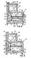
- the oven unit shown in Fig. 1is a main housing 10 about 1.7 meters in overall length, about 0.9 meters in height, and about 1.3 meters in depth.
- Housing 10defines a thermally insulated treatment zone 12 about 1.5 meters in length, about 0.8 meters in width, and about 0.7 meters in height.
- Caster wheels 14support housing 10 and permits its ready positioning at a desired location.
- a pair of spaced arms 16extend from each end of housing 10 and each pair of arms supports a roller 18 between which is trained a 0.8 meter wide food grade stainless steel wire transport belt 20 that has an open area of approximately 84 percent.
- Belt 20extends through treatment chamber 12 via openings 22, 24 in opposite end walls of housing 10.
- a removable pan 26is supported on each pair of arms 16 immediately below the upper run of conveyor belt 20.
- Access doors 28are hingedly mounted on the front wall of housing 10 and have windows 30 which permit viewing of products within treatment zone 12.
- On top of main housing 10is an auxiliary thermally insulated housing 40 that defines a conditioning plenum 42.
- a gas fired air heater 44(Fig. 2) and supported on the opposite end wall of plenum 42 is a fan 46 (Fig. 2) that is driven by a 2HP, 1750 rpm motor 48.
- Insulated hinged door 50provides access to conditioning plenum 42 and oven controls are provided on adjacent control panel 52.
- Treatment zone 12 and conditioning plenum 42are each surrounded by thermal insulation 54 (about 7.6 centimeters in thickness).
- the inner surface of treatment zone 12are stainless steel and include planar upper wall surface 56 and parallel lower wall surface 58.
- Extending parallel to and adjacent the front and rear walls of treatment zone 12are support members 60, 62, each of which has a flange 64 that supports the margin of the upper run of conveyor 20.
- Rollers 66extend between support members 60, 62 and provide supplemental transverse support for the upper run of conveyor 20, while similar rollers 68 support the lower run of conveyor 20.
- Conveyor 20is driven by motor 70 via drive belt 72 for transport of articles to be baked such as pizzas 74 through treatment zone 12..
- a vertical partition member 78that forms the forward wall of distribution plenum 80 that has in its upper wall (Fig. 6) an inlet port 82 from blower 46, curved deflection baffles 84, 86 and a series of ten cylindrical outlet port connections 88 at its lower portion.
- Vent tube 90extends upwardly from plenum 80 and has a slide type control valve 92.
- a series of ten nozzle units 100are mounted between outlet ports 88 and support rail 94 that extends along the front wall of treatment zone 12; the nozzle orifices being spaced about 7.6 centimeters below the upper run of conveyor 20, and surface 56 being spaced about 2.3 centimeters above that upper run.
- a nozzle unit 100is shown in Fig. 5.
- Each nozzle unitis of 18 gauge stainless steel and has a length of about 0.75 meters and a height of about 0.25 meters; and includes a horizontal bottom plate 102 about 11 centimeters in width, planar inclined side walls 104 that terminate in a nozzle orifice slot 106 that has a width of 0.6 centimeters and extends the length of the nozzle unit, and generally triangular end walls 108.
- Distribution baffle plate 11phas an array of 0.3 centimeter diameter holes (open area of about 23 percent) and extends the length of nozzle unit 100 parallel to base plate portion 102.
- a 9.6 centimeter diameter cylindrical coupling sleeve 112 in one end wall of each nozzle unitprovides connection to a corresponding plenum outlet 88, and a securing stud 114 projects downwardly from the bottom wall 102 at the opposite end for attachment to support rail 94.
- Spacers 116are provided along the length of discharge slot 106 to maintain the 0.6 centimeter nozzle slot opening, and flanges 118 on either side of nozzle opening 106 extend the length of the nozzle unit.
- nozzle slots 106are spaced about 14.6 centimeters apart along the length of treatment zone 12 and there is about 3.8 centimeters spacing between adjacent baseplates 102.
- Airis discharged from treatment zone 12 through exhaust port 120 below the bottom surfaces 102 of the nozzle units and between the bottom wall 122 of supply plenum 80 and the bottom wall 58 at the rear of treatment zone 12.
- Port 120communicates with a return passage 124 that extends upwardly to port 126 (Fig. 6) in the bottom wall of conditioning plenum 42.
- Service door 128 on the rear wall of housing 10provides access to return passage 124 and removable panel 130 provides access to distribution plenum 80.
- products 74 to be bakedare transported through zone 12 by conveyor 20, a typical conveyor speed being 0.3 meter per minute.
- a variety of size and types of pizzasmay be concurrently baked including "thin” pizzas 74A (a crust of about 0.3 centimeter thickness) and "deep dish” pizza pies 74B (a depth of about four centimeters) as well as a range of diameters, as indicated diagrammatically. Fully satisfactory. and uniform baking is obtained over the full range of loadings from a single pizza to a fully loaded conveyor.
- Heated air at a temperature of about 288°Cis circulated from conditioning plenum 42 by blower 46 into distribution plenum 80 and directed by distribution baffle plates 84, 86 to supply ports 88 for distribution to nozzle units 100.
- the heated airis distributed by distribution baffles plates 110 and flows upwardly from nozzle orifices 106 in parallel streams (as indicated by arrows 140) at a velocity of about 1200 meters per minute. Portions of these upwardly flowing sheet streams of air impact against the bottom surfaces of pans of products 74 with effective sweeping heat transfer action as indicated by deflection arrows 142.
- This oven systemprovides efficient and uniform cooking of pizza products 74 over a wide range of conveyor loadings (partially and fully loaded), and cooks the pizza efficiently (in about five minutes with a conveyor speed of about 0.3 meter per minute). Total oven circulation is between 50 and 65 cubic meters per minute. Air flow is controlled to minimize the escape of heat to the atmosphere.
- the systemmay be operated by relatively unskilled attendants, one attendant loading pizzas at the input end and removing and cutting pizzas from the output end during periods of moderate production, while at peak periods, one attendant may load pizzas at the input end and another attendant may remove and cut pizzas at the output end.
- the design of the nozzle units 100provides low maintenance with the sweeping air flows tending to dislodge particles which might fall through the conveyor,
- the nozzle unitsare readily accessible and individually removable when replacement is desired.
- the single array of nozzles below the conveyorprovide spaced upwardly flowing streams of heated air for heat exchange impact against food products on the conveyor. Portions of those streams that bypass the food products flow against the reflection surface and a gentle downward countercurrent flow is produced which impinges on the top surfaces of the food products being cooked and then is drawn downwardly through the conveyor for exhaust from the treatment zone.
- the process and apparatusprovides a compact, balanced, versatile, and efficient cooking environment particularly useful for baking pizza products.
Landscapes
- Life Sciences & Earth Sciences (AREA)
- Engineering & Computer Science (AREA)
- Food Science & Technology (AREA)
- Baking, Grill, Roasting (AREA)
- Bakery Products And Manufacturing Methods Therefor (AREA)
- Manufacturing And Processing Devices For Dough (AREA)
Description
- The invention relates to an oven system and a'process for cooking food substances according to the first part of the claims 1 and 8, respectively.
- Cooking of foods induces complex chemical and physical changes, and food properties such as texture, flavor, odor, and appearance frequently change relatively rapidly during the cooking process, conditions desirable for enjoyable consumption often being quite transient. Particular problems have been encountered in the cooking of food products such as pizzas, particularly in fast service restaurants where quality cooking should be efficiently accomplished in both large volume and small volume amounts. The cooking apparatus should be easy to operate and high standards of sanitation should be maintained with minimum down time and minimum operator effort and skill.
- The present invention is particularly useful in the cooking (baking) of pizzas and pizza related products. Pizzas include a pastry shell with topping ingredients such as tomato paste, cheese, seasonings, and optional other vegetable, meat, or similar ingredients. The shell of the pizza must be baked relatively slowly and the shell dough should be cooked through with a flaky tender crust that is browned but not burned, and the topping ingredients not burned. Pizza products have various styles including relatively thick pizza pies (four centrimeters or more in thickness), and thin pizza (less than about one centimeter thick) and a range of shapes and diameters within each style.
- Baking ovens are known in which air is flowed into the baking space through nozzle arrays:
- DE-AI-26 47 992: air is flowed into the baking space from nozzles above and nozzles below conveyor and exhausted from the sides of the baking space through ports.
- GB-Al-1,204,870: air is flowed from nozzle holes upwardly through conveyor belt and exhausted through exhaust ducts above conveyor by suction fan (according to the first part of claims 1 and 8).
- With reference to the last-mentioned background art it is the technical problem of the invention to provide an oven system and a process of the above-mentioned kind
- - for efficient, uniform and rapid cooking (baking), specifically not over or under cooked,
- - of a wide range of pizzas (thick and thin) and the like products simultaneously,
- -without requiring skilled cooking techniques, and
- - being tolerant of a wide range of conveyor loading with a fixed conveyor speed and a fixed cooking interval.
- The solution of this problem is achieved by the characterizing portion of the claims 1 and 8, respectively.
- In a particular embodiment the nozzle area is less than 5% of the total treatment zone area and (according to claim 9) the velocity of the downwardly flowing air is less than 10% of the velocity of the upwardly flowing air. This differential velocity interaction on the food products provides very efficient and uniform cooking of pizzas (not over or under cooked), does not require skilled cooking techniques, and is tolerant of a wide range of conveyor loadings. Both thick and thin type pizzas may be cooked concurrently and substantially independently of the conveyor loading with a fixed conveyor speed and a fixed cooking interval. In a particular embodiment a pizza product is cooked in about 5 minutes with air circulation of about 60 m3/min in a substantially closed, energy efficient system.
- In preferred embodiments, according to claims 3-5, the nozzle units are readily accessible and easily removable as required to facilitate maintenance of the oven system in a clean, sanitary condition. Preferably, treatment chamber surfaces are of stainless steel and the deflection surface is formed according to claim 7. The air flow system is preferably formed according to
claim 2. - In a particular embodiment that provides a particularly efficient, uniform, and rapid cooking of a wide range of pizzas, the treatment zone is about 1.5 m in length with discharge nozzle slot orifices that extend across the width of the treatment zone spaced at about 0.15 m intervals along the length of the treatment zone; the conveyor is operated at a speed of about 0.3 m/min; air is circulated through the oven system at a rate of about 60 m3/min in a controlled manner that minimizes escape of heat to the atmosphere, with air being discharged from the nozzles at a velocity in the order of 1220 ml min.
- A plurality of ways of carrying out the invention is described in detail below with reference to drawings which illustrate only specific embodiments, in which:
- Fig. 1 is a perspective view of an oven system in accordance with the invention;
- Fig. 2 is a sectional view taken along the line 2-2 of Fig. 1;
- Figs. 3 and 4 are sectional views taken along the line 3-3 and 4-4 respectively of Fig. 2;
- Fig. 5 is a perspective view of a nozzle unit employed in the oven shown in Fig. 1;
- Fig. 6 is a sectional view taken along the line 6-6 of Fig. 2;
- Fig. 7 is a sectional view taken along the line 7-7 of Fig. 2 showing a plan view of the conveyor system and treatment zone of the oven system; and
- Fig. 8 is a diagrammatic view illustrating air flows within the treatment zone of the oven system.
- The oven unit shown in Fig. 1 is a
main housing 10 about 1.7 meters in overall length, about 0.9 meters in height, and about 1.3 meters in depth.Housing 10 defines a thermally insulatedtreatment zone 12 about 1.5 meters in length, about 0.8 meters in width, and about 0.7 meters in height.Caster wheels 14 supporthousing 10 and permits its ready positioning at a desired location. A pair of spacedarms 16 extend from each end ofhousing 10 and each pair of arms supports aroller 18 between which is trained a 0.8 meter wide food grade stainless steelwire transport belt 20 that has an open area of approximately 84 percent.Belt 20 extends throughtreatment chamber 12 viaopenings housing 10. Aremovable pan 26 is supported on each pair ofarms 16 immediately below the upper run ofconveyor belt 20.Access doors 28 are hingedly mounted on the front wall ofhousing 10 and havewindows 30 which permit viewing of products withintreatment zone 12. On top ofmain housing 10 is an auxiliary thermally insulatedhousing 40 that defines aconditioning plenum 42. Supported from one end wall ofplenum 42 is a gas fired air heater 44 (Fig. 2) and supported on the opposite end wall ofplenum 42 is a fan 46 (Fig. 2) that is driven by a 2HP, 1750rpm motor 48. Insulated hingeddoor 50 provides access toconditioning plenum 42 and oven controls are provided onadjacent control panel 52. - Further details of oven system may be seen with reference to the sectional views of Figs. 2, 3, and 4.
Treatment zone 12 andconditioning plenum 42 are each surrounded by thermal insulation 54 (about 7.6 centimeters in thickness). The inner surface oftreatment zone 12 are stainless steel and include planarupper wall surface 56 and parallellower wall surface 58. Extending parallel to and adjacent the front and rear walls oftreatment zone 12 are supportmembers flange 64 that supports the margin of the upper run ofconveyor 20.Rollers 66 extend betweensupport members conveyor 20, whilesimilar rollers 68 support the lower run ofconveyor 20.Conveyor 20 is driven bymotor 70 viadrive belt 72 for transport of articles to be baked such as pizzas 74 throughtreatment zone 12.. - At the rear of
treatment zone 12 is avertical partition member 78 that forms the forward wall ofdistribution plenum 80 that has in its upper wall (Fig. 6) aninlet port 82 fromblower 46,curved deflection baffles outlet port connections 88 at its lower portion. Venttube 90 extends upwardly fromplenum 80 and has a slidetype control valve 92. A series of tennozzle units 100 are mounted betweenoutlet ports 88 andsupport rail 94 that extends along the front wall oftreatment zone 12; the nozzle orifices being spaced about 7.6 centimeters below the upper run ofconveyor 20, andsurface 56 being spaced about 2.3 centimeters above that upper run. - A
nozzle unit 100 is shown in Fig. 5. Each nozzle unit is of 18 gauge stainless steel and has a length of about 0.75 meters and a height of about 0.25 meters; and includes ahorizontal bottom plate 102 about 11 centimeters in width, planarinclined side walls 104 that terminate in anozzle orifice slot 106 that has a width of 0.6 centimeters and extends the length of the nozzle unit, and generallytriangular end walls 108. Distribution baffle plate 11p has an array of 0.3 centimeter diameter holes (open area of about 23 percent) and extends the length ofnozzle unit 100 parallel tobase plate portion 102. A 9.6 centimeter diametercylindrical coupling sleeve 112 in one end wall of each nozzle unit provides connection to acorresponding plenum outlet 88, and asecuring stud 114 projects downwardly from thebottom wall 102 at the opposite end for attachment to supportrail 94.Spacers 116 are provided along the length ofdischarge slot 106 to maintain the 0.6 centimeter nozzle slot opening, andflanges 118 on either side ofnozzle opening 106 extend the length of the nozzle unit. In the oven,nozzle slots 106 are spaced about 14.6 centimeters apart along the length oftreatment zone 12 and there is about 3.8 centimeters spacing betweenadjacent baseplates 102. - Air is discharged from
treatment zone 12 throughexhaust port 120 below thebottom surfaces 102 of the nozzle units and between thebottom wall 122 ofsupply plenum 80 and thebottom wall 58 at the rear oftreatment zone 12. Port 120 communicates with areturn passage 124 that extends upwardly to port 126 (Fig. 6) in the bottom wall ofconditioning plenum 42.Service door 128 on the rear wall ofhousing 10 provides access toreturn passage 124 andremovable panel 130 provides access todistribution plenum 80.- As indicated in the sectional plan view of Fig. 7 and in the diagrammatic view of Fig. 8, products 74 to be baked are transported through
zone 12 byconveyor 20, a typical conveyor speed being 0.3 meter per minute. A variety of size and types of pizzas may be concurrently baked including "thin"pizzas 74A (a crust of about 0.3 centimeter thickness) and "deep dish"pizza pies 74B (a depth of about four centimeters) as well as a range of diameters, as indicated diagrammatically. Fully satisfactory. and uniform baking is obtained over the full range of loadings from a single pizza to a fully loaded conveyor. Heated air at a temperature of about 288°C is circulated fromconditioning plenum 42 byblower 46 intodistribution plenum 80 and directed bydistribution baffle plates ports 88 for distribution tonozzle units 100. The heated air is distributed bydistribution baffles plates 110 and flows upwardly fromnozzle orifices 106 in parallel streams (as indicated by arrows 140) at a velocity of about 1200 meters per minute. Portions of these upwardly flowing sheet streams of air impact against the bottom surfaces of pans of products 74 with effective sweeping heat transfer action as indicated bydeflection arrows 142. - Other portions of these high velocity sheet streams 140 bypass products 74 and flow upwardly as indicated by
arrows 144 for impact against and deflection by upper surface 56 (as indicated by arrows 146). The deflected air flows downwardly at low velocity, as indicated byarrows 148 throughout the upper portion oftreatment zone 12 and against the upper surfaces of products 74 to provide supplemental cooking action at the upper surfaces of those products. Thus the system provides efficient primary heat exchange action at the bottoms of products 74 by impact of relatively high velocity sheet stream flow of heated air, with supplemental low velocity air flow impingement and heat exchange on the top of surfaces of products 74. Downward air flow continues throughconveyor 20 with sweeping along planarinclined side walls 104 ofnozzles 100 as indicated byarrows 150 for exhaust fromtreatment zone 12 throughexhaust port 120 and return toconditioning plenum 42 for conditioning viareturn passage 124. - This oven system provides efficient and uniform cooking of pizza products 74 over a wide range of conveyor loadings (partially and fully loaded), and cooks the pizza efficiently (in about five minutes with a conveyor speed of about 0.3 meter per minute). Total oven circulation is between 50 and 65 cubic meters per minute. Air flow is controlled to minimize the escape of heat to the atmosphere. The system may be operated by relatively unskilled attendants, one attendant loading pizzas at the input end and removing and cutting pizzas from the output end during periods of moderate production, while at peak periods, one attendant may load pizzas at the input end and another attendant may remove and cut pizzas at the output end.
- The design of the
nozzle units 100 provides low maintenance with the sweeping air flows tending to dislodge particles which might fall through the conveyor, The nozzle units are readily accessible and individually removable when replacement is desired. The single array of nozzles below the conveyor provide spaced upwardly flowing streams of heated air for heat exchange impact against food products on the conveyor. Portions of those streams that bypass the food products flow against the reflection surface and a gentle downward countercurrent flow is produced which impinges on the top surfaces of the food products being cooked and then is drawn downwardly through the conveyor for exhaust from the treatment zone. The process and apparatus provides a compact, balanced, versatile, and efficient cooking environment particularly useful for baking pizza products. - While a particular embodiment of the invention has been shown and described, various modifications will be apparent to those skilled in the art and therefore it is not intended that the invention be limited to the disclosed embodiment or to details thereof, and departures may be made therefrom within the scope of the invention as defined in the independent claims.
Claims (11)
characterized in that
Applications Claiming Priority (2)
| Application Number | Priority Date | Filing Date | Title |
|---|---|---|---|
| US266199 | 1981-05-22 | ||
| US06266199US4377109B1 (en) | 1981-05-22 | 1981-05-22 | Apparatus for baking food products such as pizzas and the like |
Publications (3)
| Publication Number | Publication Date |
|---|---|
| EP0068135A2 EP0068135A2 (en) | 1983-01-05 |
| EP0068135A3 EP0068135A3 (en) | 1983-02-16 |
| EP0068135B1true EP0068135B1 (en) | 1986-09-03 |
Family
ID=23013589
Family Applications (1)
| Application Number | Title | Priority Date | Filing Date |
|---|---|---|---|
| EP82104403AExpiredEP0068135B1 (en) | 1981-05-22 | 1982-05-19 | Oven system, and process for cooking food products |
Country Status (5)
| Country | Link |
|---|---|
| US (2) | US4377109B1 (en) |
| EP (1) | EP0068135B1 (en) |
| JP (1) | JPS57198038A (en) |
| CA (1) | CA1172513A (en) |
| DE (1) | DE3272996D1 (en) |
Families Citing this family (96)
| Publication number | Priority date | Publication date | Assignee | Title |
|---|---|---|---|---|
| USD275257S (en) | 1981-08-31 | 1984-08-28 | Aztec Machinery Company | Nozzle unit for an industrial oven |
| US4462383A (en)* | 1982-06-09 | 1984-07-31 | Lincoln Manufacturing Company, Inc. | Impingement food preparation apparatus |
| US4438572A (en)* | 1982-06-09 | 1984-03-27 | Lincoln Manufacturing Co., Inc. | Heat duct support assembly for a food preparation oven and method |
| USD275725S (en) | 1982-09-01 | 1984-10-02 | Lincoln Manufacturing Company, Inc. | Oven |
| US4563945A (en)* | 1984-11-13 | 1986-01-14 | Stein Associates, Inc. | Heat shield-steam distributor for cooking oven |
| US4716819A (en)* | 1985-05-01 | 1988-01-05 | Pizza Hut, Inc. | Heat transfer device for use in cooking pizzas |
| US4616562A (en)* | 1985-06-21 | 1986-10-14 | Kuechler Irvin R | Ventilation system for pizza ovens |
| US4749581A (en)* | 1985-09-03 | 1988-06-07 | Lincoln Foodservice Products, Inc. | Method for baking a food product |
| US4739154A (en)* | 1986-09-05 | 1988-04-19 | Baker's Pride Oven Co., Inc. | Conveyor oven design and method for using same |
| US4894207A (en)* | 1986-10-03 | 1990-01-16 | Archer Aire Industries, Inc. | Recirculating high velocity hot air sterilizing device |
| US4873107A (en)* | 1986-12-24 | 1989-10-10 | Archer Air Industries, Inc. | Air impingement tunnel oven apparatus |
| US4791861A (en)* | 1987-02-06 | 1988-12-20 | Pizza Enterprises, Inc. | Pizza storage and bake unit |
| US4817509A (en)* | 1987-02-17 | 1989-04-04 | Alternative Pioneering Systems Inc. | Air Fryer |
| US5403607A (en)* | 1987-02-17 | 1995-04-04 | American Harvest, Inc. | Method for rapidly cooking food |
| US4824644A (en)* | 1987-04-30 | 1989-04-25 | Archeraire Industries, Inc. | Recirculating high velocity hot air sterilizing device having improved internal insulation structure |
| US4834063A (en)* | 1987-05-28 | 1989-05-30 | Stein Associates, Inc. | Food cooking oven with duct fingers and method |
| US4964392A (en)* | 1988-07-05 | 1990-10-23 | Middleby Marshall Inc. | Baking oven |
| US4881519A (en)* | 1988-07-18 | 1989-11-21 | Lincoln Foodservice Products, Inc. | Hot air oven having infra-red radiant surfaces |
| GR1000309B (en)* | 1988-10-07 | 1992-05-12 | Oetker Tiefkuhldost Gmbh Dr | Method for preparating pizzas |
| DE3834167A1 (en)* | 1988-10-07 | 1990-04-12 | Oetker Tiefkuehlkost | Process for the production of pizzas |
| DE3834166A1 (en)* | 1988-10-07 | 1990-04-12 | Oetker Tiefkuehlkost | Process for the production of pizzas |
| US4924763A (en)* | 1988-10-17 | 1990-05-15 | Pizza Hut | Compact pizza oven |
| US4919477A (en)* | 1988-10-17 | 1990-04-24 | Pizza Hut, Inc. | Compact pizza preparation and delivery vehicle |
| US4951645A (en)* | 1988-12-02 | 1990-08-28 | Welbilt Corporation | Stacked duel module commercial hot air impingement cooking oven |
| US4972824A (en)* | 1988-12-02 | 1990-11-27 | Welbilt Corporation | Commercial hot air impingement cooking apparatus |
| US4960100A (en)* | 1989-03-13 | 1990-10-02 | Mastermatic, Inc. | Conveyor oven |
| US5699722A (en)* | 1989-03-17 | 1997-12-23 | Erickson; Chad | Rapid cooking device |
| US4951648A (en)* | 1989-03-23 | 1990-08-28 | Tecogen, Inc. | Conveyor oven |
| CA2024203C (en)* | 1989-09-22 | 2002-07-30 | Donald P. Smith | Balanced air return convection oven |
| US6041398A (en)* | 1992-06-26 | 2000-03-21 | International Business Machines Corporation | Massively parallel multiple-folded clustered processor mesh array |
| US5033366A (en)* | 1990-03-05 | 1991-07-23 | Sullivan Robert E | Modular food preparation station |
| US5239917A (en)* | 1991-06-06 | 1993-08-31 | Genie Tech, Inc. | Oven |
| US5180898A (en)* | 1991-07-25 | 1993-01-19 | G. S. Blodgett Corporation | High velocity conveyor oven |
| US5254823A (en)* | 1991-09-17 | 1993-10-19 | Turbochef Inc. | Quick-cooking oven |
| US5277924A (en)* | 1992-11-25 | 1994-01-11 | Proctor & Schwartz, Inc. | Radio frequency proofing and convection baking apparatus and method for making pizza |
| IT1263964B (en)* | 1993-02-24 | 1996-09-05 | Barilla Flli G & R | PROCEDURE FOR THE PRODUCTION OF REFRIGERATED PIZZAS READY TO BE CONSUMED |
| US5466912A (en)* | 1993-04-13 | 1995-11-14 | American Harvest, Inc. | Convection oven |
| US5421316A (en)* | 1994-01-31 | 1995-06-06 | G. S. Blodgett Corporation | Conveyor oven with improved air flow |
| US5532456A (en)* | 1995-03-02 | 1996-07-02 | The Delfield Company | Temperature and humidity controllable doorless oven |
| AU7362696A (en)* | 1995-09-19 | 1997-04-28 | Pillsbury Company, The | Broiler apparatus |
| US5686004A (en)* | 1996-04-29 | 1997-11-11 | Schneider; Russell C. | Pizza oven with conveyor |
| US5964044A (en)* | 1997-01-14 | 1999-10-12 | Wisconsin Oven Corporation | Conveyor oven usable as pre-bake oven in a print plate imaging and processing system and method of using same |
| AU738500B2 (en)* | 1997-02-21 | 2001-09-20 | Taco Bell Corp. | Restaurant food preparation line |
| US7092988B1 (en) | 1997-05-27 | 2006-08-15 | Jeffrey Bogatin | Rapid cooking oven with broadband communication capability to increase ease of use |
| US6066043A (en)* | 1997-12-08 | 2000-05-23 | Knisely; Charles W. | Oscillating baffle for airflow redirection and heat transfer enhancement |
| US5968578A (en)* | 1997-12-08 | 1999-10-19 | Knisely; Charles W. | Baking system and method using oscillating baffles for heat transfer enhancement |
| DE19820066A1 (en)* | 1998-05-06 | 1999-11-11 | Werner & Pfleiderer Lebensmitt | oven |
| US5881636A (en)* | 1998-07-01 | 1999-03-16 | Sweet; Dan | Heat impingement bake oven |
| US6065463A (en)* | 1998-10-19 | 2000-05-23 | Sasib Bakery North America, Inc. | Forced convective track oven |
| AU4021200A (en)* | 1999-03-23 | 2000-10-09 | Pizza Hut Inc. | Impingement oven airflow devices and methods |
| US6369360B1 (en) | 1999-05-21 | 2002-04-09 | Maytag Corporation | Combination high speed infrared and convection conveyor oven and method of using |
| US6073547A (en)* | 1999-09-13 | 2000-06-13 | Standex International Corporation | Food temperature maintenance apparatus |
| US8224892B2 (en) | 2000-04-28 | 2012-07-17 | Turbochef Technologies, Inc. | Rapid cooking oven with broadband communication capability to increase ease of use |
| US6323462B1 (en) | 2000-06-23 | 2001-11-27 | Wisconsin Oven Corporation | Conveyor oven usable as pre-bake oven in a print plate imaging and processing system and method of using same |
| US6526961B1 (en) | 2000-07-10 | 2003-03-04 | Lincoln Foodservice Products, Inc | Conveyor oven |
| US6684875B1 (en)* | 2000-11-17 | 2004-02-03 | Middleby Corporation | Conveyor oven with modulated gas flow |
| EP1408763A1 (en)* | 2001-03-22 | 2004-04-21 | Zesto Food Equipment Manufacturing Inc. | Multiconveyor convection oven |
| US6669118B2 (en)* | 2001-08-20 | 2003-12-30 | Saint-Gobain Abrasives, Inc. | Coherent jet nozzles for grinding applications |
| US6592364B2 (en) | 2001-11-30 | 2003-07-15 | David Zapata | Apparatus, method and system for independently controlling airflow in a conveyor oven |
| WO2003082024A1 (en)* | 2002-03-27 | 2003-10-09 | Endodis Corporation | Conveyorized oven with moisture laden air impingement and method |
| US7727054B2 (en)* | 2002-07-26 | 2010-06-01 | Saint-Gobain Abrasives, Inc. | Coherent jet nozzles for grinding applications |
| USD488666S1 (en) | 2002-10-10 | 2004-04-20 | Noble Roman's, Inc. | Self service kiosk |
| US20070006865A1 (en)* | 2003-02-21 | 2007-01-11 | Wiker John H | Self-cleaning oven |
| US7220946B2 (en)* | 2004-01-23 | 2007-05-22 | Hatco Corporation | Food container |
| US8087407B2 (en) | 2004-03-23 | 2012-01-03 | Middleby Corporation | Conveyor oven apparatus and method |
| US9585400B2 (en) | 2004-03-23 | 2017-03-07 | The Middleby Corporation | Conveyor oven apparatus and method |
| US7624728B1 (en) | 2004-12-22 | 2009-12-01 | David C Forbes | Impingement tunnel oven with reduced energy consumption and reduced maintenance |
| ITMI20050934A1 (en)* | 2005-05-23 | 2006-11-24 | Italpizza S P A | INDUSTRIAL OVEN WITH TUNNEL HEATED WITH WOOD FOR COOKING PIZZAS AND SIMILAR FOOD PRODUCTS |
| JP4382725B2 (en)* | 2005-09-07 | 2009-12-16 | 株式会社石野製作所 | Food heating equipment |
| US7604000B2 (en)* | 2006-12-21 | 2009-10-20 | Wolfe Electric, Inc. | Tunnel oven |
| US8134101B2 (en)* | 2007-10-11 | 2012-03-13 | Hatco Corporation | Food container |
| US20090139976A1 (en)* | 2007-12-03 | 2009-06-04 | Robert Lee | Impingement quartz conveyor oven |
| WO2010027922A1 (en)* | 2008-09-05 | 2010-03-11 | The Middleby Corporation | Recirculating end cover plates for a conveyor oven |
| US20100183779A1 (en)* | 2009-01-16 | 2010-07-22 | Perry Dean Felix | Method and apparatus for sanitizing consumable products using ultraviolet light |
| US20110005409A1 (en)* | 2009-07-10 | 2011-01-13 | Hatco Corporation | Heated air curtain container with multiple temperature zones |
| US8839714B2 (en) | 2009-08-28 | 2014-09-23 | The Middleby Corporation | Apparatus and method for controlling a conveyor oven |
| WO2011106608A1 (en)* | 2010-02-26 | 2011-09-01 | Merco/Savory Llc | Conveyor oven and method for handling heated air |
| WO2011106616A1 (en)* | 2010-02-26 | 2011-09-01 | Merco/Savory Llc | Conveyor oven and method for removal of non-seared products from a conveyor belt |
| WO2011106628A1 (en)* | 2010-02-26 | 2011-09-01 | Merco/Savory Llc | A conveyor oven and method for easy access for maintenance |
| WO2011106603A1 (en)* | 2010-02-26 | 2011-09-01 | Merco/Savory Llc | Conveyor oven and frame with cooling |
| WO2011106643A1 (en)* | 2010-02-26 | 2011-09-01 | Merco/Savory Llp | A conveyor oven with dual heater sources |
| US20140199446A1 (en)* | 2013-01-11 | 2014-07-17 | Star Manufacturing International, Inc. | Split-Belt Conveyor Toaster |
| US9144244B1 (en)* | 2013-04-19 | 2015-09-29 | James C. Harris | Grease shield smoke assembly |
| US9516883B1 (en) | 2013-07-18 | 2016-12-13 | Star Manufacturing International Inc. | Heating assembly and method for tortilla like food |
| US9677774B2 (en) | 2015-06-08 | 2017-06-13 | Alto-Shaam, Inc. | Multi-zone oven with variable cavity sizes |
| US10890336B2 (en) | 2015-06-08 | 2021-01-12 | Alto-Shaam, Inc. | Thermal management system for multizone oven |
| US10337745B2 (en) | 2015-06-08 | 2019-07-02 | Alto-Shaam, Inc. | Convection oven |
| US10088172B2 (en) | 2016-07-29 | 2018-10-02 | Alto-Shaam, Inc. | Oven using structured air |
| US9879865B2 (en) | 2015-06-08 | 2018-01-30 | Alto-Shaam, Inc. | Cooking oven |
| NZ746496A (en)* | 2016-03-09 | 2021-12-24 | Dmp Entpr Pty Ltd | Conveyor-type oven |
| FR3055771B1 (en)* | 2016-09-14 | 2018-08-24 | Mecatherm | LINEAR TUNNEL OVEN COOKING MODULE FOR BAKERY PRODUCTS, VIENNOISERIE AND THE LIKE AND LINEAR TUNNEL OVEN HAVING AT LEAST ONE SUCH MODULE |
| US11045047B2 (en) | 2017-11-10 | 2021-06-29 | Ron's Enterprises, Inc. | Variable capacity oven |
| US11134690B1 (en)* | 2018-04-19 | 2021-10-05 | Michael French | Pizza oven and a method of using a pizza oven |
| US11497217B2 (en) | 2019-09-09 | 2022-11-15 | Wolfe Electric, Inc. | Air impingement conveyor oven |
| DE102021204166B4 (en)* | 2021-04-27 | 2025-03-13 | Heuft Thermo-Oel GmbH & Co. KG | Tunnel kiln |
| CN215305176U (en)* | 2021-06-15 | 2021-12-28 | 江门市新会恒隆家居创新用品有限公司 | Toaster |
Family Cites Families (30)
| Publication number | Priority date | Publication date | Assignee | Title |
|---|---|---|---|---|
| US1647872A (en)* | 1925-10-06 | 1927-11-01 | Leavitt James Quincy | Peeler |
| US1656709A (en)* | 1927-01-27 | 1928-01-17 | Standard Electric Stove Co | Electric oven |
| DE565523C (en)* | 1930-12-12 | 1932-12-01 | Willy Klenk Dipl Ing | Traveling stove oven with a pre-baking area arranged in front of the baking area and containing steaming and heating devices |
| US2076479A (en)* | 1935-01-12 | 1937-04-06 | Connell S Inc O | Automatic toaster |
| US2112309A (en)* | 1936-10-16 | 1938-03-29 | Santillan Miguel | Grill for tortillas and the like |
| US2244670A (en)* | 1939-10-30 | 1941-06-10 | Edward L Benedict | Cooking and vending machine |
| GB579895A (en)* | 1945-01-20 | 1946-08-20 | William Wycliffe Spooner | Improvements in the cooking of alimentary products |
| US3227065A (en)* | 1963-06-07 | 1966-01-04 | Alan L Litman | Waterless egg cooker |
| US3379141A (en)* | 1965-06-14 | 1968-04-23 | Pasquale Associates Inc | Method and apparatus for forming pizza shells |
| US3340794A (en)* | 1966-03-18 | 1967-09-12 | Giuliano Anthony Philip | Cooking device |
| GB1204870A (en)* | 1967-12-12 | 1970-09-09 | Fr Winkler K G Spezialfabrik F | A baking oven with means for air circulation |
| LU60362A1 (en)* | 1970-02-17 | 1971-07-15 | ||
| US3646880A (en)* | 1970-08-21 | 1972-03-07 | Thermal Process Engineering Co | Cooking grill |
| BE789508A (en)* | 1971-10-08 | 1973-01-15 | Werner & Pfleiderer | CONTINUOUS TUNNEL OVEN FOR COOKING OR DRYING |
| US3873755A (en)* | 1972-01-10 | 1975-03-25 | Haberstroh Farm Products Inc | Method for precooking bacon |
| US3786741A (en)* | 1972-08-04 | 1974-01-22 | E Plumley | Smoking and cooking apparatus |
| US3757671A (en)* | 1972-10-30 | 1973-09-11 | Electric Char B Que Inc | Food preparation unit |
| US3908533A (en)* | 1973-04-04 | 1975-09-30 | Electrolux Ab | Apparatus for continuously cooking food in sequential oven section of an elongated oven |
| DE2409370A1 (en)* | 1974-02-27 | 1975-09-04 | Theo Anschuetz | Thermal processing system for food - comprises a closable two-part container with detachable hot air circulator and swivel-mounted on frame |
| GB1566799A (en)* | 1975-10-21 | 1980-05-08 | Meincke P | Baking ovens |
| US4154861A (en)* | 1976-05-19 | 1979-05-15 | Smith Donald P | Heat treatment of food products |
| US4112912A (en)* | 1976-06-16 | 1978-09-12 | Ballentine Earle W | Gas broiler |
| US4023007A (en)* | 1976-06-28 | 1977-05-10 | N.P.I. Corporation | Broiler with an endless bar conveyor |
| US4121509A (en)* | 1977-01-10 | 1978-10-24 | N.P.I. Corporation | Controlled atmosphere broiler |
| US4151791A (en)* | 1978-01-23 | 1979-05-01 | Npi Corporation | Energy conserving broiler |
| US4176589A (en)* | 1978-02-27 | 1979-12-04 | Marshall Air Systems, Inc. | Cooking apparatus |
| SE409164B (en)* | 1978-06-19 | 1979-08-06 | Tipe Revent Ab | BAKUGN |
| US4188868A (en)* | 1978-09-18 | 1980-02-19 | Npi Corporation | Energy conserver for broilers |
| US4244285A (en)* | 1979-08-17 | 1981-01-13 | Baker James F | Oven |
| US4384513A (en)* | 1981-05-07 | 1983-05-24 | Pierick Richard L | Apparatus for preparing pizza in a baking oven |
- 1981
- 1981-05-22USUS06266199patent/US4377109B1/ennot_activeExpired - Lifetime
- 1982
- 1982-03-31CACA000400022Apatent/CA1172513A/ennot_activeExpired
- 1982-05-19DEDE8282104403Tpatent/DE3272996D1/ennot_activeExpired
- 1982-05-19EPEP82104403Apatent/EP0068135B1/ennot_activeExpired
- 1982-05-21JPJP57086367Apatent/JPS57198038A/enactiveGranted
- 1982-08-13USUS06407736patent/US4471000B1/ennot_activeExpired - Lifetime
Also Published As
| Publication number | Publication date |
|---|---|
| US4471000A (en) | 1984-09-11 |
| DE3272996D1 (en) | 1986-10-09 |
| US4471000B1 (en) | 1996-03-26 |
| EP0068135A2 (en) | 1983-01-05 |
| JPS57198038A (en) | 1982-12-04 |
| JPS6361901B2 (en) | 1988-11-30 |
| US4377109A (en) | 1983-03-22 |
| EP0068135A3 (en) | 1983-02-16 |
| CA1172513A (en) | 1984-08-14 |
| US4377109B1 (en) | 1996-08-06 |
Similar Documents
| Publication | Publication Date | Title |
|---|---|---|
| EP0068135B1 (en) | Oven system, and process for cooking food products | |
| US5180898A (en) | High velocity conveyor oven | |
| US4951648A (en) | Conveyor oven | |
| US6259064B1 (en) | Concentric air delivery and return oven | |
| ES2658067T3 (en) | Quick cook oven | |
| US4781169A (en) | Oven with radiant panel | |
| CA1278965C (en) | Food cooking oven with duct fingers and method | |
| US4965435A (en) | Forced convection tunnel oven | |
| EP1797758B1 (en) | Continuous cooking oven system | |
| US4972824A (en) | Commercial hot air impingement cooking apparatus | |
| US4631029A (en) | Baking oven with heated air distribution-II | |
| KR100247864B1 (en) | Heat treatment apparatus and method of food | |
| EP0482255B1 (en) | Forced convection tunnel oven | |
| EP1421885B1 (en) | High speed variable size toaster | |
| US4591333A (en) | Impingement oven with radiant panel | |
| US5172682A (en) | Commercial hot air impingement cooking apparatus | |
| EP2074369B1 (en) | Impinging air ovens having high mass flow orifices | |
| JPH0738775B2 (en) | Cooking food products in process steam at progressively variable rates | |
| JPH02249443A (en) | Oven apparatus, oven, griddle, glill apparatus and pizza cocking method | |
| US3873755A (en) | Method for precooking bacon | |
| RU2146449C1 (en) | Bread baking oven | |
| CA2028330C (en) | Forced convection tunnel oven | |
| RU8871U1 (en) | BAKERY FURNACE | |
| AU626239B2 (en) | Forced convection tunnel oven | |
| WO2000013528A1 (en) | Air impingement oven |
Legal Events
| Date | Code | Title | Description |
|---|---|---|---|
| PUAI | Public reference made under article 153(3) epc to a published international application that has entered the european phase | Free format text:ORIGINAL CODE: 0009012 | |
| PUAL | Search report despatched | Free format text:ORIGINAL CODE: 0009013 | |
| AK | Designated contracting states | Designated state(s):BE CH DE FR GB IT LI NL | |
| AK | Designated contracting states | Designated state(s):BE CH DE FR GB IT LI NL | |
| 17P | Request for examination filed | Effective date:19830712 | |
| GRAA | (expected) grant | Free format text:ORIGINAL CODE: 0009210 | |
| AK | Designated contracting states | Kind code of ref document:B1 Designated state(s):BE CH DE FR GB IT LI NL | |
| REF | Corresponds to: | Ref document number:3272996 Country of ref document:DE Date of ref document:19861009 | |
| ITF | It: translation for a ep patent filed | ||
| ET | Fr: translation filed | ||
| PLBE | No opposition filed within time limit | Free format text:ORIGINAL CODE: 0009261 | |
| STAA | Information on the status of an ep patent application or granted ep patent | Free format text:STATUS: NO OPPOSITION FILED WITHIN TIME LIMIT | |
| 26N | No opposition filed | ||
| ITTA | It: last paid annual fee | ||
| PGFP | Annual fee paid to national office [announced via postgrant information from national office to epo] | Ref country code:FR Payment date:19960415 Year of fee payment:15 | |
| PGFP | Annual fee paid to national office [announced via postgrant information from national office to epo] | Ref country code:NL Payment date:19960417 Year of fee payment:15 | |
| PGFP | Annual fee paid to national office [announced via postgrant information from national office to epo] | Ref country code:DE Payment date:19960423 Year of fee payment:15 | |
| PGFP | Annual fee paid to national office [announced via postgrant information from national office to epo] | Ref country code:GB Payment date:19960425 Year of fee payment:15 | |
| PGFP | Annual fee paid to national office [announced via postgrant information from national office to epo] | Ref country code:CH Payment date:19960429 Year of fee payment:15 | |
| PGFP | Annual fee paid to national office [announced via postgrant information from national office to epo] | Ref country code:BE Payment date:19960430 Year of fee payment:15 | |
| PG25 | Lapsed in a contracting state [announced via postgrant information from national office to epo] | Ref country code:GB Effective date:19970519 | |
| PG25 | Lapsed in a contracting state [announced via postgrant information from national office to epo] | Ref country code:LI Free format text:LAPSE BECAUSE OF NON-PAYMENT OF DUE FEES Effective date:19970531 Ref country code:CH Free format text:LAPSE BECAUSE OF NON-PAYMENT OF DUE FEES Effective date:19970531 Ref country code:BE Effective date:19970531 | |
| BERE | Be: lapsed | Owner name:WOLVERINE CORP. Effective date:19970531 | |
| PG25 | Lapsed in a contracting state [announced via postgrant information from national office to epo] | Ref country code:NL Effective date:19971201 | |
| GBPC | Gb: european patent ceased through non-payment of renewal fee | Effective date:19970519 | |
| REG | Reference to a national code | Ref country code:CH Ref legal event code:PL | |
| PG25 | Lapsed in a contracting state [announced via postgrant information from national office to epo] | Ref country code:FR Free format text:LAPSE BECAUSE OF NON-PAYMENT OF DUE FEES Effective date:19980130 | |
| NLV4 | Nl: lapsed or anulled due to non-payment of the annual fee | Effective date:19971201 | |
| PG25 | Lapsed in a contracting state [announced via postgrant information from national office to epo] | Ref country code:DE Free format text:LAPSE BECAUSE OF NON-PAYMENT OF DUE FEES Effective date:19980203 | |
| REG | Reference to a national code | Ref country code:FR Ref legal event code:ST |