EP0067470B1 - Display tube and method of manufacturing a display screen for such a display tube - Google Patents
Display tube and method of manufacturing a display screen for such a display tubeDownload PDFInfo
- Publication number
- EP0067470B1 EP0067470B1EP82200655AEP82200655AEP0067470B1EP 0067470 B1EP0067470 B1EP 0067470B1EP 82200655 AEP82200655 AEP 82200655AEP 82200655 AEP82200655 AEP 82200655AEP 0067470 B1EP0067470 B1EP 0067470B1
- Authority
- EP
- European Patent Office
- Prior art keywords
- display
- display screen
- carbon particles
- tube
- aluminium
- Prior art date
- Legal status (The legal status is an assumption and is not a legal conclusion. Google has not performed a legal analysis and makes no representation as to the accuracy of the status listed.)
- Expired
Links
- 238000004519manufacturing processMethods0.000titleclaimsdescription8
- 239000004411aluminiumSubstances0.000claimsdescription47
- XAGFODPZIPBFFR-UHFFFAOYSA-NaluminiumChemical compound[Al]XAGFODPZIPBFFR-UHFFFAOYSA-N0.000claimsdescription47
- 229910052782aluminiumInorganic materials0.000claimsdescription47
- OKTJSMMVPCPJKN-UHFFFAOYSA-NCarbonChemical compound[C]OKTJSMMVPCPJKN-UHFFFAOYSA-N0.000claimsdescription46
- 229910052799carbonInorganic materials0.000claimsdescription44
- 229910000147aluminium phosphateInorganic materials0.000claimsdescription41
- NBIIXXVUZAFLBC-UHFFFAOYSA-NPhosphoric acidChemical compoundOP(O)(O)=ONBIIXXVUZAFLBC-UHFFFAOYSA-N0.000claimsdescription40
- 239000002245particleSubstances0.000claimsdescription27
- ILRRQNADMUWWFW-UHFFFAOYSA-Kaluminium phosphateChemical compoundO1[Al]2OP1(=O)O2ILRRQNADMUWWFW-UHFFFAOYSA-K0.000claimsdescription22
- 229940001007aluminium phosphateDrugs0.000claimsdescription19
- 238000000034methodMethods0.000claimsdescription15
- 238000010894electron beam technologyMethods0.000claimsdescription10
- 239000000243solutionSubstances0.000claimsdescription8
- 239000011358absorbing materialSubstances0.000claimsdescription7
- 238000000151depositionMethods0.000claimsdescription7
- 238000001035dryingMethods0.000claimsdescription6
- 239000000463materialSubstances0.000claimsdescription6
- 238000005507sprayingMethods0.000claimsdescription6
- 239000007864aqueous solutionSubstances0.000claimsdescription4
- 239000003086colorantSubstances0.000claimsdescription4
- 238000005260corrosionMethods0.000description11
- 230000007797corrosionEffects0.000description11
- OAICVXFJPJFONN-UHFFFAOYSA-NPhosphorusChemical compound[P]OAICVXFJPJFONN-UHFFFAOYSA-N0.000description4
- 239000012634fragmentSubstances0.000description3
- 239000011521glassSubstances0.000description3
- 239000011159matrix materialSubstances0.000description3
- 230000005855radiationEffects0.000description3
- 229910019142PO4Inorganic materials0.000description2
- 239000011230binding agentSubstances0.000description2
- 239000011248coating agentSubstances0.000description2
- 238000000576coating methodMethods0.000description2
- 230000008021depositionEffects0.000description2
- 239000010439graphiteSubstances0.000description2
- 229910002804graphiteInorganic materials0.000description2
- 230000002401inhibitory effectEffects0.000description2
- 238000007689inspectionMethods0.000description2
- 235000021317phosphateNutrition0.000description2
- 238000007789sealingMethods0.000description2
- 238000010521absorption reactionMethods0.000description1
- 238000002485combustion reactionMethods0.000description1
- 238000003487electrochemical reactionMethods0.000description1
- 238000002474experimental methodMethods0.000description1
- -1for exampleChemical class0.000description1
- 239000000615nonconductorSubstances0.000description1
- NBIIXXVUZAFLBC-UHFFFAOYSA-KphosphateChemical compound[O-]P([O-])([O-])=ONBIIXXVUZAFLBC-UHFFFAOYSA-K0.000description1
- 239000010452phosphateSubstances0.000description1
- 150000003013phosphoric acid derivativesChemical class0.000description1
- 239000011253protective coatingSubstances0.000description1
- 150000004760silicatesChemical class0.000description1
- 239000007921spraySubstances0.000description1
- XLYOFNOQVPJJNP-UHFFFAOYSA-NwaterSubstancesOXLYOFNOQVPJJNP-UHFFFAOYSA-N0.000description1
Images
Classifications
- H—ELECTRICITY
- H01—ELECTRIC ELEMENTS
- H01J—ELECTRIC DISCHARGE TUBES OR DISCHARGE LAMPS
- H01J29/00—Details of cathode-ray tubes or of electron-beam tubes of the types covered by group H01J31/00
- H01J29/02—Electrodes; Screens; Mounting, supporting, spacing or insulating thereof
- H01J29/10—Screens on or from which an image or pattern is formed, picked up, converted or stored
- H01J29/18—Luminescent screens
- H01J29/30—Luminescent screens with luminescent material discontinuously arranged, e.g. in dots, in lines
- H01J29/32—Luminescent screens with luminescent material discontinuously arranged, e.g. in dots, in lines with adjacent dots or lines of different luminescent material, e.g. for colour television
- H01J29/327—Black matrix materials
- H—ELECTRICITY
- H01—ELECTRIC ELEMENTS
- H01J—ELECTRIC DISCHARGE TUBES OR DISCHARGE LAMPS
- H01J29/00—Details of cathode-ray tubes or of electron-beam tubes of the types covered by group H01J31/00
- H01J29/02—Electrodes; Screens; Mounting, supporting, spacing or insulating thereof
- H01J29/10—Screens on or from which an image or pattern is formed, picked up, converted or stored
- H01J29/18—Luminescent screens
- H01J29/28—Luminescent screens with protective, conductive or reflective layers
- H—ELECTRICITY
- H01—ELECTRIC ELEMENTS
- H01J—ELECTRIC DISCHARGE TUBES OR DISCHARGE LAMPS
- H01J9/00—Apparatus or processes specially adapted for the manufacture, installation, removal, maintenance of electric discharge tubes, discharge lamps, or parts thereof; Recovery of material from discharge tubes or lamps
- H01J9/20—Manufacture of screens on or from which an image or pattern is formed, picked up, converted or stored; Applying coatings to the vessel
- H01J9/22—Applying luminescent coatings
- H01J9/227—Applying luminescent coatings with luminescent material discontinuously arranged, e.g. in dots or lines
Definitions
- the inventionrelates to a display tube comprising an evacuated envelope having a display window and containing means to generate at least one electron beam which is deflected over a display screen, which display screen is provided on the inside of the display window and which display screen comprises a luminescent layer on which a thin electron-permeable aluminium film is provided, said display screen moreover comprising carbon particles.
- the inventionalso relates to methods of manufacturing a display screen for such a display tube.
- the aluminium film in such a display tubeensures an increase of the brightness of the picture in that said film operates as a mirror which reflects a part of the light generated in the luminescent layer through the display window in the direction of the viewer.
- the luminescent layer in D.G.D.-tubesoften consist of material luminescing in one colour.
- Such tubesmay also be tubes for displaying coloured pictures.
- the luminescent layer of the display screenconsists in that case often of a large number of triplets of elements luminescing in three different colours and separated or not separated by light-absorbing material.
- a colour selection electrode in the tubeeach of the three electron beams generated in the tube is associated with luminescent elements of one colour. The most frequently used colour selection electrode is the shadow mask.
- Such a display tubeis known from Netherlands Patent Application 6800398 laid open to public inspection in which a colour display tube having post-acceleration and post-focusing is described.
- a porous carbon layeris provided on the thin aluminium film so as to absorb the greater part of the secondary and reflected electrons which occur in such a post-acceleration tube.
- Netherlands Patent Application 6916046discloses a colour display tube in which a layer of graphite (carbon) is used on the aluminium film so as to absorb the thermal radiation originating from the colour selection electrode.
- the electron beams in a colour tubeimpinge on the colour selection electrode or the display screen and produce thermal energy there. Inter alia because more electrons impinge on the colour selection electrode, the latter becomes warmer.
- said aluminium filmbears a heat-absorbing carbon layer.
- the aluminium film on which a porous heat-absorbing and/or secondary and reflected electrons-absorbing porous layer of carbon particles was providedcorroded in a moist atmosphere.
- the corrosion of the aluminiumoccurs in particular in those places where the aluminium film is in contact with the carbon particles and where an electrochemical reaction occurs between water and aluminium.
- the most important factoris the relative humidity of the atmosphere. At a relative humidity of 80% or higher the corrosion of the aluminium film is so large that measures have to be taken to protect the aluminium film.
- Another object of the inventionis to provide methods of manufacturing such a display tube.
- a display tube of the kind described in the opening paragraphis characterized in that the aluminium film is covered with aluminium phosphate at least at the area where it adjoins the carbon particles.
- the said aluminium phosphate coatingensures that substantially no corrosion of the aluminium film occurs.
- a first preferred embodiment of a display tube according to the inventionis characterized in that a porous, electron-permeable containing layer comprising carbon particles is provided on the aluminium film and the aluminium film is covered at least partly with aluminium phosphate on the side of the porous layer containing carbon particles, at least at the area where the carbon particles adjoin the aluminium.
- a porous carbon particles containing layeris black for thermal radiation.
- the screenreadily absorbs thermal energy but also readily radiates thermal energy.
- the thermal energy generated by the electron beam in the luminescent materialis rapidly dissipated by radiation so that the display screen can be loaded more heavily (a larger beam current is admissible) and a brighter picture can be obtained. This is of importance in particular in projection television display tubes.
- Such a porous layermay also be used for thermal absorption in a colour display tube which is characterized in that the luminescent layer of the display screen comprises a large number of triplets of elements luminescing in three different colours, in front of which display screen a colour selection electrode is provided which associates each of the three electron beams generated in the tube with luminescent elements of one colour.
- a colour display tubeis disclosed in the already mentioned Netherlands Patent Application 6916046 laid open to public inspection.
- British Patent Specification 810,110discloses a colour display tube in which between the luminescent elements of the display screen carbon (graphite) as provided which absorbs light which impinges on the display screen from without and thus increases the contrast of the colour display screen.
- a colour display tubeis also termed a matrix colour display tube.
- an aluminium filmis provided over the luminescent elements and the carbon.
- the aluminium filmis covered with aluminium phosphate at least at the area where it adjoins the light-absorbing material (carbon).
- the first two steps of this processmay be intercharged.
- the phosphoric acidis adsorbed on the carbon.
- the phosphoric acidreacts with the aluminium and forms aluminium phosphate.
- the said phosphate layerhas corrosion-inhibiting properties.
- AIP0 4aluminium phosphate
- the concentration of AIP0 4 in H a P0 4determines for a part the properties of the formed binder.
- This concentrationmay be expressed in the mole ratio P 2 0,/Al . 0 3 which preferably is between 2 and 4.
- the aluminium phosphate after dryingremains in the carbon layer so that the latter adheres even better. This reduces the occurrence of undesired loose carbon particles in the display screen.
- the combustion of the carbon particles during sealing the display window to the remainder of the envelopeis considerably reduced. During this sealing process, approximately 40% of the carbon particles burns without the use of the method.
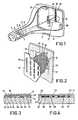
- FIG. 1is a broken-away elevation of a colour-display tube according to the invention.
- a neck 1 of a glass envelope 2are three electron guns 3, 4 and 5 for generating three electron beams 6, 7 and 8 which are focused on a display screen 9 on the inside of a display window 10 which is the sealed to a display tube cone 11 and which are deflected over said display screen in two mutually perpendicular directions.
- the three electron beams 6, 7 and 8enclose a small angle with each other and pass through a colour selection electrode 12 via apertures 13 and thus impinge each on one of the luminescent elements 14, 15 and 16 each made of a phosphor luminescing in a different colour.
- the display screenconsists of a very large number of said triplets of phosphor lines of which only three are shown.
- Figure 2is an elevation of a part of the colour selection electrode and of the display window 10 with the display screen 9 present thereon.
- An aluminium film 17 on which a porous layer 18 of carbon is providedis present over the triplets of phosphor lines.
- FIG. 3is a sectional view of a fragment of the display window with the display screen present thereon.
- the luminescent elements 14, 15 and 16are provided in the usual manner on the glass of the display window 10.
- a porous layer 18 consisting of carbon particles 19is provided in an average thickness of 0.3 pm and a weight of 0.1 to 0.2 mg/cm 2 .
- a corrosion reducing layer 20 of aluminium phosphateis formed at the surface of the aluminium film. This layer has an average thickness of 0.5 pm. If in addition aluminium phosphate is also dissolved in the phosphoric acid solution, aluminium phosphates. also deposit between the grains 19 of the porous carbon layer 18 as a result of which the adhesion of the grains 19 becomes even better.
- FIG 4is a sectional view analogous to Figure 3 but now of a colour display tube of the matrix type.
- the luminescent elements 34, 35 and 36are provided on the glass of the display window 30 between which elements light-absorbing elements 31 of carbon are provided.
- a 0.2 pm thick aluminium film 32is vapour- deposited over said luminescent elements and the light-absorbing carbon on which, just as in the display screen shown in Figure 3, a porous carbon layer may again be provided (not shown in this Figure).
- phosphoric acidis adsorbed on the carbon.
- aluminium phosphate 33After vapour deposition of the aluminium film, said phosphoric acid reacts with the aluminium and aluminium phosphate 33 is formed.
- This aluminium phosphatehas an amorphous structure, is a good electrical insulator and gives corrosion-inhibiting properties to the aluminium film so that substantially no corrosion occurs at a large relative humidity (95%) for a very long time (2 to 3 weeks).
Landscapes
- Engineering & Computer Science (AREA)
- Manufacturing & Machinery (AREA)
- Cathode-Ray Tubes And Fluorescent Screens For Display (AREA)
- Formation Of Various Coating Films On Cathode Ray Tubes And Lamps (AREA)
- Vessels, Lead-In Wires, Accessory Apparatuses For Cathode-Ray Tubes (AREA)
Description
- The invention relates to a display tube comprising an evacuated envelope having a display window and containing means to generate at least one electron beam which is deflected over a display screen, which display screen is provided on the inside of the display window and which display screen comprises a luminescent layer on which a thin electron-permeable aluminium film is provided, said display screen moreover comprising carbon particles.
- The invention also relates to methods of manufacturing a display screen for such a display tube.
- The aluminium film in such a display tube ensures an increase of the brightness of the picture in that said film operates as a mirror which reflects a part of the light generated in the luminescent layer through the display window in the direction of the viewer.
- Such display tubes may be tubes for monochromatic display of pictures, for example black-and-white television display tubes, projection television display tubes, cathode ray tubes as used in oscilloscopes and tubes for displaying letters, digits and characters (the so- called D.G.D.-tubes; D.G.D.=Data Graphic Display). The luminescent layer in D.G.D.-tubes often consist of material luminescing in one colour.
- However, such tubes may also be tubes for displaying coloured pictures. The luminescent layer of the display screen consists in that case often of a large number of triplets of elements luminescing in three different colours and separated or not separated by light-absorbing material. By using a colour selection electrode in the tube each of the three electron beams generated in the tube is associated with luminescent elements of one colour. The most frequently used colour selection electrode is the shadow mask.
- Such a display tube is known from Netherlands Patent Application 6800398 laid open to public inspection in which a colour display tube having post-acceleration and post-focusing is described. A porous carbon layer is provided on the thin aluminium film so as to absorb the greater part of the secondary and reflected electrons which occur in such a post-acceleration tube. Netherlands Patent Application 6916046 discloses a colour display tube in which a layer of graphite (carbon) is used on the aluminium film so as to absorb the thermal radiation originating from the colour selection electrode. The electron beams in a colour tube impinge on the colour selection electrode or the display screen and produce thermal energy there. Inter alia because more electrons impinge on the colour selection electrode, the latter becomes warmer. In order to prevent the thermal energy radiated from the colour selection electrode to the display screen from being reflected by the aluminium film to the colour selection electrode, said aluminium film bears a heat-absorbing carbon layer.
- In the manufacture of display tubes it has been found that the aluminium film on which a porous heat-absorbing and/or secondary and reflected electrons-absorbing porous layer of carbon particles was provided, corroded in a moist atmosphere. The corrosion of the aluminium occurs in particular in those places where the aluminium film is in contact with the carbon particles and where an electrochemical reaction occurs between water and aluminium. The most important factor is the relative humidity of the atmosphere. At a relative humidity of 80% or higher the corrosion of the aluminium film is so large that measures have to be taken to protect the aluminium film.
- Such corrosion of the aluminium film also occurred in colour display tubes in which light absorbing material consisting mainly of carbon particles was provided between the luminescent elements.
- It is therefore an object of the invention to provide a display tube in which measures are taken to substantially prevent corrosion of the aluminium film.
- Another object of the invention is to provide methods of manufacturing such a display tube. According to the invention, a display tube of the kind described in the opening paragraph is characterized in that the aluminium film is covered with aluminium phosphate at least at the area where it adjoins the carbon particles. The said aluminium phosphate coating ensures that substantially no corrosion of the aluminium film occurs.
- A first preferred embodiment of a display tube according to the invention is characterized in that a porous, electron-permeable containing layer comprising carbon particles is provided on the aluminium film and the aluminium film is covered at least partly with aluminium phosphate on the side of the porous layer containing carbon particles, at least at the area where the carbon particles adjoin the aluminium. Such a porous carbon particles containing layer is black for thermal radiation. This means that the screen readily absorbs thermal energy but also readily radiates thermal energy. By providing such a thermally black layer on the aluminium film of the display screen, the thermal energy generated by the electron beam in the luminescent material is rapidly dissipated by radiation so that the display screen can be loaded more heavily (a larger beam current is admissible) and a brighter picture can be obtained. This is of importance in particular in projection television display tubes.
- However, such a porous layer may also be used for thermal absorption in a colour display tube which is characterized in that the luminescent layer of the display screen comprises a large number of triplets of elements luminescing in three different colours, in front of which display screen a colour selection electrode is provided which associates each of the three electron beams generated in the tube with luminescent elements of one colour. Such a colour display tube is disclosed in the already mentioned Netherlands Patent Application 6916046 laid open to public inspection.
- In order to obtain the aluminium phosphate coating of the aluminium film it is possible to spray or rinse same with a phosphoric acid solution prior to providing the porous carbon layer. It is known from US-A-2 564 864 to provide a protective coating of aluminium phosphate on aluminium to increase its corrosion resistance.
- A preferred method of manufacturing a display screen for a display tube in accordance with the invention is characterized in that the method comprises the following steps:
- - providing a luminescent layer
- -vapour-depositing an aluminium film over 'the luminescent layer
- -providing a porous layer containing carbon particles
- - spraying or rinsing said porous layer containing carbon particles with an aqueous solution of phosphoric acid containing at most 2% by weight of phosphoric acid
- - drying the display screen.
- British Patent Specification 810,110 discloses a colour display tube in which between the luminescent elements of the display screen carbon (graphite) as provided which absorbs light which impinges on the display screen from without and thus increases the contrast of the colour display screen. Such a colour display tube is also termed a matrix colour display tube. Again an aluminium film is provided over the luminescent elements and the carbon. In order to prevent corrosion of said aluminium film at the area where it is in contact with the carbon particles, according to the invention the aluminium film is covered with aluminium phosphate at least at the area where it adjoins the light-absorbing material (carbon).
- A preferred method of manufacturing such a display screen is characterized in that the method comprises the following steps:
- -providing a pattern of triplets of luminescent elements
- -providing porous light-absorbing material consisting mainly of carbon particles between the luminescent elements
- -spraying or rinsing said material and the luminescent elements with an aqueous solution of phosphoric acid containing at most 2% by weight of phosphoric acid,
- - drying the provided material and the luminescent elements
- - vapour-depositing the aluminium film.
- As is known, the first two steps of this process may be intercharged. In this method the phosphoric acid is adsorbed on the carbon. After drying the screen and vapour-depositing the aluminium film the phosphoric acid reacts with the aluminium and forms aluminium phosphate. During the further finishing of the tube the said phosphate layer has corrosion-inhibiting properties. It is also possible to use the two above mentioned methods which have been modified by using a phosphoric acid solution which also contains 0.1 to 2.0% by weight of aluminium phosphate (AIP04). Since phosphates, like for example, silicates, can polymerize, said aluminium phosphate solution forms a binder with very good adhesion properties. Experiments have demonstrated that the concentration of AIP04 in HaP04 determines for a part the properties of the formed binder. This concentration may be expressed in the mole ratio P20,/Al.03 which preferably is between 2 and 4. The aluminium phosphate after drying remains in the carbon layer so that the latter adheres even better. This reduces the occurrence of undesired loose carbon particles in the display screen. Moreover it has been found that upon using the above-mentioned first method the combustion of the carbon particles during sealing the display window to the remainder of the envelope is considerably reduced. During this sealing process, approximately 40% of the carbon particles burns without the use of the method. When using the method in which the porous layer comprising carbon particles is sprayed with a phosphoric acid solution or with a phosphoric acid solution in which aluminium phosphate has been dissolved in the phosphoric acid, this is reduced to 20%. As a result of this it is possible to obtain a more constant blacking quality of the porous layer.
- The invention will now be described in greater detail, by way of example, with reference to a drawing, in which:
- Figure 1 is a broken-away elevation of a colour-display tube according to the invention,
- Figure 2 is an elevation of a part of the colour selection electrode and of the display window with the display screen present thereon,
- Figure 3 is a sectional view on an enlarged scale of a fragment of the display window with the display screen present thereon and
- Figure 4 is a sectional view of a fragment of the display window with the display screen present thereon of a colour display tube according to the invention of the matrix type.
- Figure 1 is a broken-away elevation of a colour-display tube according to the invention. Present in a
neck 1 of aglass envelope 2 are threeelectron guns electron beams 6, 7 and 8 which are focused on adisplay screen 9 on the inside of adisplay window 10 which is the sealed to adisplay tube cone 11 and which are deflected over said display screen in two mutually perpendicular directions. The threeelectron beams 6, 7 and 8 enclose a small angle with each other and pass through acolour selection electrode 12 viaapertures 13 and thus impinge each on one of theluminescent elements - Figure 2 is an elevation of a part of the colour selection electrode and of the
display window 10 with thedisplay screen 9 present thereon. Analuminium film 17 on which aporous layer 18 of carbon is provided is present over the triplets of phosphor lines. - Figure 3 is a sectional view of a fragment of the display window with the display screen present thereon. The
luminescent elements display window 10. Over the elements which usually consist of a phosphor, a 0.3 pm thick aluminium film is vapour deposited on which aporous layer 18 consisting ofcarbon particles 19 is provided in an average thickness of 0.3 pm and a weight of 0.1 to 0.2 mg/cm2. By rinsing or spraying thealuminium film 17 coated with theporous layer 18 of carbon with the phosphoric acid solution described, acorrosion reducing layer 20 of aluminium phosphate is formed at the surface of the aluminium film. This layer has an average thickness of 0.5 pm. If in addition aluminium phosphate is also dissolved in the phosphoric acid solution, aluminium phosphates. also deposit between thegrains 19 of theporous carbon layer 18 as a result of which the adhesion of thegrains 19 becomes even better. - Figure 4 is a sectional view analogous to Figure 3 but now of a colour display tube of the matrix type. In the usual manner, for example via a photographic or electrophotographic process, the
luminescent elements display window 30 between which elements light-absorbingelements 31 of carbon are provided. A 0.2 pmthick aluminium film 32 is vapour- deposited over said luminescent elements and the light-absorbing carbon on which, just as in the display screen shown in Figure 3, a porous carbon layer may again be provided (not shown in this Figure). By rinsing or spraying the luminescent elements and the light-absorbing carbon therebetween prior to vapour deposition of the aluminium film, phosphoric acid is adsorbed on the carbon. After vapour deposition of the aluminium film, said phosphoric acid reacts with the aluminium andaluminium phosphate 33 is formed. This aluminium phosphate has an amorphous structure, is a good electrical insulator and gives corrosion-inhibiting properties to the aluminium film so that substantially no corrosion occurs at a large relative humidity (95%) for a very long time (2 to 3 weeks).
Claims (8)
Applications Claiming Priority (2)
| Application Number | Priority Date | Filing Date | Title |
|---|---|---|---|
| NL8102689 | 1981-06-03 | ||
| NL8102689ANL8102689A (en) | 1981-06-03 | 1981-06-03 | IMAGE TUBE AND METHOD FOR MANUFACTURING AN IMAGE SCREEN FOR SUCH AN IMAGE TUBE |
Publications (2)
| Publication Number | Publication Date |
|---|---|
| EP0067470A1 EP0067470A1 (en) | 1982-12-22 |
| EP0067470B1true EP0067470B1 (en) | 1985-02-13 |
Family
ID=19837597
Family Applications (1)
| Application Number | Title | Priority Date | Filing Date |
|---|---|---|---|
| EP82200655AExpiredEP0067470B1 (en) | 1981-06-03 | 1982-05-28 | Display tube and method of manufacturing a display screen for such a display tube |
Country Status (8)
| Country | Link |
|---|---|
| US (1) | US4551652A (en) |
| EP (1) | EP0067470B1 (en) |
| JP (1) | JPS57210541A (en) |
| CA (1) | CA1184232A (en) |
| DD (1) | DD202355A5 (en) |
| DE (1) | DE3262304D1 (en) |
| ES (1) | ES512735A0 (en) |
| NL (1) | NL8102689A (en) |
Families Citing this family (16)
| Publication number | Priority date | Publication date | Assignee | Title |
|---|---|---|---|---|
| JPS6113535A (en)* | 1984-06-28 | 1986-01-21 | Sony Corp | Cathode-ray tube |
| JPH0326617Y2 (en)* | 1984-09-17 | 1991-06-10 | ||
| JPS6174244A (en)* | 1984-09-18 | 1986-04-16 | Sanyo Electric Co Ltd | Flat-type color chathode-ray tube |
| US4682075A (en)* | 1985-12-19 | 1987-07-21 | Rca Corporation | Image display including improved light-absorbing matrix |
| KR960016719B1 (en)* | 1993-02-08 | 1996-12-20 | 마쯔시다덴기산교 가부시기가이샤 | Electron beam display device and manufacturing method |
| US5786663A (en)* | 1994-12-01 | 1998-07-28 | Commissariat A L'energie Atomique | Electron collector having independently controllable conductive strips |
| EP0720201B1 (en)* | 1994-12-26 | 1999-02-17 | Kabushiki Kaisha Toshiba | Display screen and method of manufacturing the same |
| JPH09180657A (en)* | 1995-12-22 | 1997-07-11 | Futaba Corp | Fluorescent character display tube |
| AT405933B (en)* | 1996-11-13 | 1999-12-27 | Kwizda Fa F Johann | USE OF MODIFIED WASTE PRODUCTS OF CELLULAR EXTRACTION AS A HIGH QUALITY Peat Substitution |
| FR2758002B1 (en)* | 1996-12-27 | 2004-07-02 | Thomson Tubes Electroniques | VISUALIZATION SYSTEM WITH LUMINESCENT OBSERVATION SCREEN |
| US6461415B1 (en) | 2000-08-23 | 2002-10-08 | Applied Thin Films, Inc. | High temperature amorphous composition based on aluminum phosphate |
| US20040248956A1 (en)* | 2002-01-29 | 2004-12-09 | Hagmann William K | Substituted imidazoles as cannabinoid receptor modulators |
| US7678465B2 (en)* | 2002-07-24 | 2010-03-16 | Applied Thin Films, Inc. | Aluminum phosphate compounds, compositions, materials and related metal coatings |
| US7682700B2 (en) | 2002-08-14 | 2010-03-23 | Applied Thin Films, Inc. | Aluminum phosphate compounds, compositions, materials and related composites |
| WO2005003033A2 (en)* | 2002-12-23 | 2005-01-13 | Applied Thin Films, Inc. | Aluminum phosphate coatings |
| WO2004104111A1 (en)* | 2003-05-22 | 2004-12-02 | Kemira Pigments Oy | Inorganic light-absorbing micropigments and the use thereof |
Family Cites Families (6)
| Publication number | Priority date | Publication date | Assignee | Title |
|---|---|---|---|---|
| NL6916046A (en)* | 1969-10-23 | 1971-04-27 | ||
| US3703401A (en)* | 1970-12-28 | 1972-11-21 | Rca Corp | Method for preparing the viewing-screen structure of a cathode-ray tube |
| US4025661A (en)* | 1972-11-13 | 1977-05-24 | Rca Corporation | Method of making viewing-screen structure for a cathode-ray tube |
| JPS4979169A (en)* | 1972-12-04 | 1974-07-31 | ||
| JPS49107173A (en)* | 1973-02-14 | 1974-10-11 | ||
| US4407916A (en)* | 1981-03-19 | 1983-10-04 | Hitachi, Ltd. | Process for forming fluorescent screen |
- 1981
- 1981-06-03NLNL8102689Apatent/NL8102689A/ennot_activeApplication Discontinuation
- 1982
- 1982-05-27CACA000403924Apatent/CA1184232A/ennot_activeExpired
- 1982-05-28DEDE8282200655Tpatent/DE3262304D1/ennot_activeExpired
- 1982-05-28EPEP82200655Apatent/EP0067470B1/ennot_activeExpired
- 1982-06-01USUS06/383,844patent/US4551652A/ennot_activeExpired - Fee Related
- 1982-06-01ESES512735Apatent/ES512735A0/enactiveGranted
- 1982-06-03JPJP57094166Apatent/JPS57210541A/enactiveGranted
- 1983
- 1983-06-03DDDD83240439Apatent/DD202355A5/enunknown
Also Published As
| Publication number | Publication date |
|---|---|
| ES8304709A1 (en) | 1983-03-01 |
| JPS57210541A (en) | 1982-12-24 |
| DD202355A5 (en) | 1983-09-07 |
| CA1184232A (en) | 1985-03-19 |
| EP0067470A1 (en) | 1982-12-22 |
| ES512735A0 (en) | 1983-03-01 |
| DE3262304D1 (en) | 1985-03-28 |
| NL8102689A (en) | 1983-01-03 |
| US4551652A (en) | 1985-11-05 |
| JPH0241861B2 (en) | 1990-09-19 |
Similar Documents
| Publication | Publication Date | Title |
|---|---|---|
| EP0067470B1 (en) | Display tube and method of manufacturing a display screen for such a display tube | |
| US3392297A (en) | Color triad tube having heat-absorptive material on aluminum screen backing for cooling shadow mask | |
| US4884004A (en) | Color cathode-ray tube having a heat dissipative, electron reflective coating on a color selection electrode | |
| US3911165A (en) | Method of fabricating secondary electron emission preventive film and colour picture tube having same | |
| EP0403165B1 (en) | Method for manufacturing color cathode ray tube | |
| US5028836A (en) | Color cathode ray tube of shadow mask type | |
| US4188562A (en) | Color display tube and method of manufacturing such a color display tube | |
| EP0144022A1 (en) | Color picture tube | |
| US3582701A (en) | Color tube screen with light-absorbing cermet deposits | |
| US3979632A (en) | Cathode ray tube having surface charge inhibiting means therein | |
| US3621318A (en) | Color television picture tube with metallic film coating on funnel portion | |
| US2960416A (en) | Method of manufacturing screens for electron-discharge devices | |
| EP0137411B1 (en) | Color picture tube | |
| US5633559A (en) | Color display tube having color selection structure with rough surface | |
| US5039551A (en) | Method of manufacturing a phosphor screen of a cathode ray tube | |
| CA1101915A (en) | Colour display tube with light-absorbing matrix | |
| US3480482A (en) | Method for making storage targets for cathode ray tubes | |
| US2198327A (en) | Mosaic electrode structure | |
| US3138734A (en) | Prevention of cathode poisoning in an electron tube | |
| US3778266A (en) | Method of forming a black patterned portion on a phosphor screen of a cathode-ray tube for color television sets | |
| CA1052436A (en) | Apertured electron-absorbing layer on screen of cathode ray tube for displaying coloured pictures | |
| JP2865902B2 (en) | Method for manufacturing color cathode ray tube to minimize thermal deformation of shadow mask | |
| JP2964939B2 (en) | Color cathode ray tube | |
| JPS62188135A (en) | Color picture tube | |
| JPH0775147B2 (en) | Color picture tube |
Legal Events
| Date | Code | Title | Description |
|---|---|---|---|
| PUAI | Public reference made under article 153(3) epc to a published international application that has entered the european phase | Free format text:ORIGINAL CODE: 0009012 | |
| AK | Designated contracting states | Designated state(s):DE FR GB IT NL | |
| 17P | Request for examination filed | Effective date:19820528 | |
| ITF | It: translation for a ep patent filed | ||
| GRAA | (expected) grant | Free format text:ORIGINAL CODE: 0009210 | |
| AK | Designated contracting states | Designated state(s):DE FR GB IT NL | |
| REF | Corresponds to: | Ref document number:3262304 Country of ref document:DE Date of ref document:19850328 | |
| ET | Fr: translation filed | ||
| PLBE | No opposition filed within time limit | Free format text:ORIGINAL CODE: 0009261 | |
| STAA | Information on the status of an ep patent application or granted ep patent | Free format text:STATUS: NO OPPOSITION FILED WITHIN TIME LIMIT | |
| 26N | No opposition filed | ||
| PGFP | Annual fee paid to national office [announced via postgrant information from national office to epo] | Ref country code:NL Payment date:19870531 Year of fee payment:6 | |
| PG25 | Lapsed in a contracting state [announced via postgrant information from national office to epo] | Ref country code:NL Effective date:19891201 | |
| NLV4 | Nl: lapsed or anulled due to non-payment of the annual fee | ||
| PGFP | Annual fee paid to national office [announced via postgrant information from national office to epo] | Ref country code:GB Payment date:19920430 Year of fee payment:11 | |
| PGFP | Annual fee paid to national office [announced via postgrant information from national office to epo] | Ref country code:FR Payment date:19920519 Year of fee payment:11 | |
| ITTA | It: last paid annual fee | ||
| PGFP | Annual fee paid to national office [announced via postgrant information from national office to epo] | Ref country code:DE Payment date:19920724 Year of fee payment:11 | |
| PG25 | Lapsed in a contracting state [announced via postgrant information from national office to epo] | Ref country code:GB Effective date:19930528 | |
| GBPC | Gb: european patent ceased through non-payment of renewal fee | Effective date:19930528 | |
| PG25 | Lapsed in a contracting state [announced via postgrant information from national office to epo] | Ref country code:FR Effective date:19940131 | |
| PG25 | Lapsed in a contracting state [announced via postgrant information from national office to epo] | Ref country code:DE Effective date:19940201 | |
| REG | Reference to a national code | Ref country code:FR Ref legal event code:ST |