EP0067298A1 - Electromagnetic actuator with position detection - Google Patents
Electromagnetic actuator with position detectionDownload PDFInfo
- Publication number
- EP0067298A1 EP0067298A1EP82103747AEP82103747AEP0067298A1EP 0067298 A1EP0067298 A1EP 0067298A1EP 82103747 AEP82103747 AEP 82103747AEP 82103747 AEP82103747 AEP 82103747AEP 0067298 A1EP0067298 A1EP 0067298A1
- Authority
- EP
- European Patent Office
- Prior art keywords
- measuring coil
- armature
- temperature
- voltage
- diodes
- Prior art date
- Legal status (The legal status is an assumption and is not a legal conclusion. Google has not performed a legal analysis and makes no representation as to the accuracy of the status listed.)
- Granted
Links
- 238000001514detection methodMethods0.000titleclaimsabstractdescription7
- 238000004804windingMethods0.000claimsabstractdescription17
- 230000001939inductive effectEffects0.000claimsabstractdescription7
- 238000007885magnetic separationMethods0.000claimsdescription3
- 230000001419dependent effectEffects0.000description11
- 230000004907fluxEffects0.000description9
- 238000010586diagramMethods0.000description5
- 239000010453quartzSubstances0.000description2
- VYPSYNLAJGMNEJ-UHFFFAOYSA-Nsilicon dioxideInorganic materialsO=[Si]=OVYPSYNLAJGMNEJ-UHFFFAOYSA-N0.000description2
- 230000003321amplificationEffects0.000description1
- 238000006243chemical reactionMethods0.000description1
- 238000011161developmentMethods0.000description1
- 230000018109developmental processEffects0.000description1
- 230000000694effectsEffects0.000description1
- 230000007613environmental effectEffects0.000description1
- 239000012530fluidSubstances0.000description1
- 238000009434installationMethods0.000description1
- 238000003199nucleic acid amplification methodMethods0.000description1
- 230000001105regulatory effectEffects0.000description1
Images


Classifications
- H—ELECTRICITY
- H01—ELECTRIC ELEMENTS
- H01F—MAGNETS; INDUCTANCES; TRANSFORMERS; SELECTION OF MATERIALS FOR THEIR MAGNETIC PROPERTIES
- H01F7/00—Magnets
- H01F7/06—Electromagnets; Actuators including electromagnets
- H01F7/08—Electromagnets; Actuators including electromagnets with armatures
- H01F7/16—Rectilinearly-movable armatures
- H01F7/1607—Armatures entering the winding
- G—PHYSICS
- G05—CONTROLLING; REGULATING
- G05D—SYSTEMS FOR CONTROLLING OR REGULATING NON-ELECTRIC VARIABLES
- G05D23/00—Control of temperature
- G05D23/19—Control of temperature characterised by the use of electric means
- G05D23/1906—Control of temperature characterised by the use of electric means using an analogue comparing device
- G—PHYSICS
- G05—CONTROLLING; REGULATING
- G05D—SYSTEMS FOR CONTROLLING OR REGULATING NON-ELECTRIC VARIABLES
- G05D23/00—Control of temperature
- G05D23/19—Control of temperature characterised by the use of electric means
- G05D23/20—Control of temperature characterised by the use of electric means with sensing elements having variation of electric or magnetic properties with change of temperature
- G—PHYSICS
- G12—INSTRUMENT DETAILS
- G12B—CONSTRUCTIONAL DETAILS OF INSTRUMENTS, OR COMPARABLE DETAILS OF OTHER APPARATUS, NOT OTHERWISE PROVIDED FOR
- G12B7/00—Compensating for the effects of temperature
- H—ELECTRICITY
- H01—ELECTRIC ELEMENTS
- H01F—MAGNETS; INDUCTANCES; TRANSFORMERS; SELECTION OF MATERIALS FOR THEIR MAGNETIC PROPERTIES
- H01F7/00—Magnets
- H01F7/06—Electromagnets; Actuators including electromagnets
- H01F7/08—Electromagnets; Actuators including electromagnets with armatures
- H01F7/16—Rectilinearly-movable armatures
- H01F2007/1684—Armature position measurement using coils
- H—ELECTRICITY
- H01—ELECTRIC ELEMENTS
- H01F—MAGNETS; INDUCTANCES; TRANSFORMERS; SELECTION OF MATERIALS FOR THEIR MAGNETIC PROPERTIES
- H01F7/00—Magnets
- H01F7/06—Electromagnets; Actuators including electromagnets
- H01F7/08—Electromagnets; Actuators including electromagnets with armatures
- H01F7/18—Circuit arrangements for obtaining desired operating characteristics, e.g. for slow operation, for sequential energisation of windings, for high-speed energisation of windings
- H01F7/1844—Monitoring or fail-safe circuits
- H01F2007/185—Monitoring or fail-safe circuits with armature position measurement
Definitions
- the inventionrelates to an electrically actuated solenoid with stroke position detection according to the preamble of claim 1.
- a solenoid of this typeis known from -DE-OS 29 30 995.
- Such lifting magnetsare e.g. used for actuating valves, the valve body being connected to the armature of the lifting magnet via a rod.
- the stroke position of the armatureis determined as the actual value and compared with a predetermined target value, and the actuating current supplied to the working winding of the solenoid is controlled in accordance with the control deviation determined in this way.
- the stroke position detection for determining the actual valueconsists in this known solenoid in a measuring coil, which is arranged axially after the working winding on the soft magnetic armature guide part in the region of a non-magnetic joint, which is swept by one end of the armature during its axial movement.
- the inductance of the measuring coilchanges depending on how far the joint is bridged by the armature.
- the measuring coilis fed with an alternating voltage and its inductive resistance for stroke position detection is determined.
- a second measuring coilis provided to compensate for the temperature response, which is in heat-conducting contact with the first measuring coil, the inductance of which, however, is not influenced by the stroke position of the armature.
- the change in the inductive resistance of the first measuring coilis determined by comparison with the resistance of the second measuring coil, so that the same temperature-dependent ohmic resistance for both measuring coils has no influence.
- the second measuring coilincreases the costs and the space requirement.
- the inventionhas for its object to effect the compensation of the temperature response of the measuring coil with less effort and space.
- the respective current temperature of the measuring coilis determined by the temperature sensor arranged on the measuring coil.
- the alternating voltage feeding the measuring coilis varied in accordance with this instantaneous temperature, so that just the ohmic resistance of the measuring coil corresponding to this instantaneous temperature is compensated.
- the temperature compensationis effected by a simple, inexpensive electronic circuit. Only the temperature sensor must be arranged on the measuring coil itself, while the rest of the electronic circuit does not have to be integrated into the lifting magnet. The dimensions of the lifting magnet that are essential for the installation are therefore not influenced by the temperature compensation.
- any electronic component with a temperature-dependent characteristiccan be used as a temperature sensor; e.g. a thermocouple or a temperature-dependent resistor.
- Diodes that are fed with a constant currentare preferably used as temperature sensors. The voltage drop across these diodes is then directly proportional to the temperature.
- the alternating voltage feeding the measuring coilcan be varied in proportion to the temperature in order to compensate for the ohmic resistance of the measuring coil which increases proportionally with the temperature.
- temperature sensorsare preferably distributed over the circumference of the measuring coil.
- Four diodes connected in seriesare preferably arranged around the measuring coil.
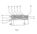
- the lifting magnet shown in FIG. 1has a soft magnetic armature 10, to which an non-magnetic piston rod 12 is connected.
- the piston rodacts against a spring force on an actuator, not shown, for example a valve body.
- the armature 10is guided in an axially displaceable manner in a soft magnetic armature guide part 14 designed as a pressure tube.
- the lifting movement of the armature 10is limited on the one hand by the closed end of the armature guide part 14 and on the other hand by a stop 16 inserted into this armature guide part.
- a first non-magnetic parting line 18interrupts the armature guide part 14 in the region of the end of the stroke path of the armature 10 facing the stop 16.
- the lifting magnetcan be attached directly to a hydraulic system using a flange plate using fastening screws. Bores in the stop 16 and the armature 10 allow the pressurized hydraulic fluid to enter both sides of the armature 10.
- a measuring coil 24is seated on the axial extension of the armature guide part 14.
- the armature guide part 14has a second non-magnetic separation joint 26 in the area of the measuring coil 24.
- a magnetic flux return part 30closes the magnetic circuit of the measuring coil 24.
- the magnetic flux return part 30is separated on its end face facing the working winding 22 by a gap filled with a radial plastic disk 32 from the magnetic flux return part 28 of the working winding 22. This prevents the magnetic flux of the working winding 22 from spreading over the magnetic flux of the measuring coil 24.
- the inductive resistance of the measuring coil 24is variable and depends on how far the second non-magnetic separation joint 26 is bridged by the armature 10, and thus on the stroke position of the armature 10 which is dependent on the current strength feeding the working winding 22.
- the working winding 22, the armature 10 and the measuring coil 24 of the solenoidare shown schematically.
- the measuring coil 24is fed with an alternating voltage U 2 , which is generated from a direct voltage U by means of a transistor 34 which is opened and closed by a quartz oscillator 36 with a frequency converter 38 connected downstream.
- the DC voltage Uis varied to compensate for the temperature-dependent ohmic resistance of the measuring coil 24 in accordance with the temperature V determined by a temperature sensor 40 arranged on the measuring coil 24.
- the temperature compensation circuit 42 indicated schematically in FIG. 2will be explained in detail later.
- the measuring coil 24is connected in series with an ohmic measuring resistor 44.
- the alternating current flowing through the measuring coil 24is of the inductive resistance of the measuring coil 24, i.e. depending on the stroke position of the armature 10.
- the voltage drop occurring at the measuring resistor 44 in accordance with this stroke position-dependent alternating currentis rectified via a precision rectifier 46 and fed to an input of a control amplifier 48 with P-I behavior.
- the other input of the control amplifier 48is supplied with the target value of the armature stroke position as a DC voltage signal. This target value is entered by a potentiometer 50 and an amplifier 52.
- the R egelverParkr 48compares the actual value of the stroke position representing output of the precision rectifier 46 to the target value-representing output signal of the amplifier 52 and regulated in accordance with the control deviation with a switching regulator 54 to the A rbeitswicklung 22 supplied current, so that the control deviation becomes zero and the armature adopts the target stroke position entered.
- the current supplied to the working winding 22is additionally superimposed on a dither frequency by a dither 56 in order to prevent the armature or the actuator actuated by it from becoming stuck.
- the temperature compensation circuit 42is shown in detail in FIG.
- the temperature sensor 40is formed by a diode which is connected to a constant current source 58. Instead of the one diode 40 shown in FIG. 3, four diodes connected in series, which are arranged distributed over the circumference of the measuring coil 24, are preferably used in practice.
- the voltage drop across the diode 40which is directly proportional to the temperature of the diode 40 or the measuring coil 24, is fed to one input of a differential operational amplifier 60.
- An adjustable DC voltageis fed to the other input of the differential operational amplifier 60 via a potentiometer 62.
- the negative feedback resistor 64 of the operational amplifier 60is also variably adjustable.
- the DC voltage at the output of the differential operational amplifier 60is controlled by the quartz-controlled transistor 34 in FIG an AC voltage U 4 is converted with a frequency of, for example, 200 Hz.
- This alternating voltage U 4which is dependent on the temperature of the diode 40 or the measuring coil 24, is converted via an operational amplifier 66 and a transistor 68, which are used for impedance conversion, into the equally large, temperature-dependent alternating voltage U 2 , which feeds the measuring coil 24.
- the voltageis fed in, which corresponds to the voltage drop of the diode 40 at the high temperature.
- the gain of the operational amplifier 60ie the slope of the linear dependence of the voltage U 4 on the temperature ⁇ shown in FIG. 4, is set such that the voltage U 4 determined empirically for this high temperature is obtained. Due to the linear dependence, temperature compensation is achieved over the entire temperature range.
Landscapes
- Physics & Mathematics (AREA)
- Engineering & Computer Science (AREA)
- General Physics & Mathematics (AREA)
- Automation & Control Theory (AREA)
- Electromagnetism (AREA)
- Power Engineering (AREA)
- Measurement Of Length, Angles, Or The Like Using Electric Or Magnetic Means (AREA)
- Magnetically Actuated Valves (AREA)
- Valve Device For Special Equipments (AREA)
Abstract
Description
Translated fromGermanDie Erfindung betrifft einen elektrisch betätigten Hubmagneten mit Hublageerkennung gemäß Oberbegriff des Patentanspruchs 1.The invention relates to an electrically actuated solenoid with stroke position detection according to the preamble of claim 1.
Ein Hubmagnet dieser Gattung ist aus der -DE-OS 29 30 995 bekannt. Solche Hubmagnete werden z.B. zur Betätigung von Ventilen eingesetzt, wobei der Ventilkörper über eine Stange mit dem Anker des Hubmagneten verbunden ist. Zur Regelung der Ventilstellung wird die Hublage des Ankers als Ist-Wert bestimmt und mit einem vorgegebenen Soll-Wert verglichen, und der der Arbeitswicklung des Hubmagneten zugeführte Betätigungsstrom wird entsprechend der so ermittelten Regelabweichung gesteuert.A solenoid of this type is known from -DE-OS 29 30 995. Such lifting magnets are e.g. used for actuating valves, the valve body being connected to the armature of the lifting magnet via a rod. To control the valve position, the stroke position of the armature is determined as the actual value and compared with a predetermined target value, and the actuating current supplied to the working winding of the solenoid is controlled in accordance with the control deviation determined in this way.
Die Hublageerkennung zur Ermittlung des Ist-Wertes besteht bei diesem bekannten Hubmagneten in einer Meßspule, die axial anschließend an die Arbeitswicklung auf dem weichmagnetischen Ankerführungsteil im Bereich einer unmagnetischen Trennfuge angeordnet ist, die von dem einen Ende des Ankers bei dessen Axialbewegung überstrichen wird. Die Induktivität der Meßspule ändert sich je nach dem, wie weit die Trennfuge durch den Anker überbrückt wird. Die Meßspule wird mit einer Wechselspannung gespeist und ihr induktiver Widerstand zur Hublageerkennung bestimmt.The stroke position detection for determining the actual value consists in this known solenoid in a measuring coil, which is arranged axially after the working winding on the soft magnetic armature guide part in the region of a non-magnetic joint, which is swept by one end of the armature during its axial movement. The inductance of the measuring coil changes depending on how far the joint is bridged by the armature. The measuring coil is fed with an alternating voltage and its inductive resistance for stroke position detection is determined.
Zu dem induktiven Widerstand der Meßspule kommt deren temperaturabhängiger ohmscher Widerstand hinzu. Da sich die Temperatur der Meßspule, insbesondere durch die unterschiedliche Stromstärke der Arbeitswiddung und durch Umwelteinflüsse. ändert, ändert sich auch ihr ohmscher Widerstand, was zur Verfälschung des ermittelten Hublage-Ist-Wertes führt.In addition to the inductive resistance of the measuring coil, its temperature-dependent ohmic resistance is added. As the temperature of the measuring coil changes, in particular due to the different current intensity of the working winding and environmental influences. changes, their ohmic resistance also changes, which leads to falsification of the ascertained actual stroke position value.
Bei dem bekannten Hubmagneten ist zur Kompensation des Temperaturganges eine zweite Meßspule vorgesehen, die in wärmeleitendem Kontakt mit der ersten Meßspule steht, deren Induktivität aber nicht durch die Hublage des Ankers beeinflußt wird. Die Änderung des induktiven Widerstandes der ersten Meßspule wird durch Vergleich mit dem Widerstand der zweiten Meßspule ermittelt, so daß der für beide Meßspulen gleiche temperaturabhängige ohmsche Widerstand ohne Einfluß ist.In the known solenoids, a second measuring coil is provided to compensate for the temperature response, which is in heat-conducting contact with the first measuring coil, the inductance of which, however, is not influenced by the stroke position of the armature. The change in the inductive resistance of the first measuring coil is determined by comparison with the resistance of the second measuring coil, so that the same temperature-dependent ohmic resistance for both measuring coils has no influence.
Die zweite Meßspule erhöht bei der bekannten Hublageerkennung die Kosten und den Platzbedarf.With the known stroke position detection, the second measuring coil increases the costs and the space requirement.
Der Erfindung liegt die Aufgabe zugrunde, die Kompensation des Temperaturganges der Meßspule mit geringerem Aufwand und Platzbedarf zu bewirken.The invention has for its object to effect the compensation of the temperature response of the measuring coil with less effort and space.
Diese Aufgabe wird bei einem Hubmagneten der eingangs genannten Gattung erfindungsgemäß gelöst durch die Merkmale des kennzeichnenden Teils des Patentanspruchs 1.This object is achieved according to the invention in the case of a lifting magnet of the type mentioned at the outset by the features of the characterizing part of patent claim 1.
Vorteilhafte Ausführungsformen und Weiterbildungen der Erfindung sind in den Unteransprüchen angegeben.Advantageous embodiments and developments of the invention are specified in the subclaims.
Durch den an der Meßspule angeordneten Temperaturfühler wird die jeweilige momentane Temperatur der Meßspule festgestellt. Die die Meßspule speisende Wechselspannung wird entsprechend dieser momentanen Temperatur variiert, so daß gerade der dieser momentanen Temperatur entsprechende ohmsche Widerstand der Meßspule kompensiert wird. Die Temperaturkompensation wird durch eine einfache, wenig aufwendige elektronische Schaltung bewirkt. An der Meßspule selbst muß nur der Temperaturfühler angeordnet sein, während die übrige elektronische Schaltung nicht in den Hubmagneten integriert werden muß. Die für den Einbau wesentlichen Abmessungen des Hubmagneten werden daher durch die Temperaturkompensation nicht beeinflußt.The respective current temperature of the measuring coil is determined by the temperature sensor arranged on the measuring coil. The alternating voltage feeding the measuring coil is varied in accordance with this instantaneous temperature, so that just the ohmic resistance of the measuring coil corresponding to this instantaneous temperature is compensated. The temperature compensation is effected by a simple, inexpensive electronic circuit. Only the temperature sensor must be arranged on the measuring coil itself, while the rest of the electronic circuit does not have to be integrated into the lifting magnet. The dimensions of the lifting magnet that are essential for the installation are therefore not influenced by the temperature compensation.
Als Temperaturfühler kann prinzipiell jedes elektronische Bauelement mit einer temperaturabhängigen Kennlinie verwendet werden; z.B. ein Thermoelement oder ein temperaturabhängiger Widerstand. Vorzugsweise werden als Temperaturfühler Dioden verwendet, die mit einem konstanten Strom gespeist werden. Der Spannungsabfall über diese Dioden ist dann direkt proportional der Temperatur. Dadurch läßt sich in einfacher Weise die die Meßspule speisende Wechselspannung proportional der Temperatur variieren, um den propor- )tional mit der Temperatur ansteigenden ohmschen Widerstand der Meßspule zu kompensieren.In principle, any electronic component with a temperature-dependent characteristic can be used as a temperature sensor; e.g. a thermocouple or a temperature-dependent resistor. Diodes that are fed with a constant current are preferably used as temperature sensors. The voltage drop across these diodes is then directly proportional to the temperature. As a result, the alternating voltage feeding the measuring coil can be varied in proportion to the temperature in order to compensate for the ohmic resistance of the measuring coil which increases proportionally with the temperature.
Um eine eventuelle ungleichmäßige Temperaturverteilung innerhalb der Meßspule zu berücksichtigen, sind vorzugsweise mehrere Temperaturfühler über den Umfang der Meßspule verteilt. Vorzugsweise werden vier in Reihe geschaltete Dioden um die Meßspule herum angeordnet.In order to take into account a possible uneven temperature distribution within the measuring coil, several temperature sensors are preferably distributed over the circumference of the measuring coil. Four diodes connected in series are preferably arranged around the measuring coil.
Im folgenden wird die Erfindung anhand eines in der Zeichnung dargestellten Ausführungsbeispiels näher erläutert.The invention is explained in more detail below on the basis of an exemplary embodiment shown in the drawing.
Es zeigen:
- Figur 1 einen in der oberen Hälfte axial geschnittenen Hubmagneten,
- Figur 2 in einem Blockschaltbild die gesamte Hublagenregelung des Hubmagneten,
- Figur 3 ein Schaltbild der Temperaturkompensation der Meßspule des Hubmagneten und
- Figur 4 in einem'Diagramm die Temperaturkompensation.
- FIG. 1 shows a lifting magnet cut axially in the upper half,
- FIG. 2 shows the entire stroke position control of the lifting magnet in a block diagram,
- Figure 3 is a circuit diagram of the temperature compensation of the measuring coil of the solenoid and
- FIG. 4 shows the temperature compensation in a diagram.
Der in Figur 1 dargestellte Hubmagnet weist einen weichmagnetischen Anker 10 auf, mit dem eine unmagnetische Kolbenstange 12 verbunden ist. Die Kolbenstange wirkt gegen eine Federkraft auf ein nicht dargestelltes Stellglied, beispielsweise einen Ventilkörper, ein. Der Anker 10 wird in einem als Druckrohr ausgebildeten weichmagnetischen Ankerführungsteil 14 axial verschiebbar geführt. Die Hubbewegung des Ankers 10 wird einerseits durch das geschlossene Ende des Ankerführungsteils 14 und andererseits durch einen in diesen Ankerführungsteil eingesetzten Anschlag 16 begrenzt. Eine erste unmagnetische Trennfuge 18 unterbricht den Ankerführungsteil 14 im Bereich des dem Anschlag 16 zugewandten Ende des Hubweges des Ankers 10.The lifting magnet shown in FIG. 1 has a soft
Auf dem Ankerführungsteil 14 sitzt ein Spulenkörper 20, auf welchen eine Arbeitswicklung 22 gewickelt ist. Ein weichmagnetisches Magnetfluß-Rückschlußteil 28 schließt den Magnetkreis des Ankerführungsteils 14 außen um die Arbeitswicklung 22. Der Hubmagnet kann mit einer Flanschplatte mittels Befestigungsschrauben unmittelbar an einem hydraulischen System angebaut werden. Bohrungen in dem Anschlag 16 und dem Anker 10 ermöglichen den Eintritt des unter Druck stehenden Hydraulikfluids auf beide Seiten des Ankers 10.On the
Ein axial vorspringender Ansatz des Ankers 10 mit einer für die Führung des Magnetflußes ausreichenden radialen Dicke ragt über den Magnetfluß-Rückschlußsteil 28 axial hinaus. Ebenso ist der Ankerführungsteil 14 über den Magnetfluß-"Rückschlußteil 28 hinaus axial verlängert.An axially projecting approach of the
Auf der axialen Verlängerung des Ankerführungsteil 14 sitzt eine Meßspule 24. Der Ankerführungsteil 14 weist im Bereich der Meßspule 24 eine zweite unmagnetische Trennfuge 26 auf. Ein Magnetfluß-Rückschlußteil 30 schließt den Magnetkreis der Meßspule 24. Der Magnetfluß-Rückschlußteil 30 ist an seiner der Arbeitswicklung 22 zugewandten Stirnfläche durch einen mit einer radialen Kunststoffscheibe 32 ausgefüllten Spalt von dem Magnetfluß-Rückschlußteil 28 der Arbeitswicklung 22 getrennt. Dadurch wird ein Übergreifen des Magnetflußes der Arbeitswicklung 22 auf den Magnetfluß der Meßspule 24 vermieden.A
Der induktive Widerstand der Meßspule 24 ist veränderlich und hängt davon ab, wie weit die zweite unmagnetische Trennfuge 26 durch den Anker 10 überbrückt wird, und somit von der durch die die Arbeitswicklung 22 speisenden Stromstärke abhängige Hublage des Ankers 10.The inductive resistance of the
Anhand des Blockschaltbildes der Figur 2 wird die Regelung der Hublage des Hubmagneten erläutert.The control of the stroke position of the solenoid is explained on the basis of the block diagram in FIG.
Im Blockschaltbild der Figur 2 sind die Arbeitswicklung 22, der Anker 10 und die Meßspule 24 des Hubmagneten schematisch dargestellt. Die Meßspule 24 wird mit einer Wechselspannung U2 gespeist, die aus einer Gleichspannung U mittels eines Transistors 34 erzeugt wird, der durch einen Quarzoszillator 36 mit nachgeschaltetem Frequenzumformer 38 auf- und zugesteuert wird. Die Gleichspannung U wird zur Kompensation des temperaturabhängigen ohmschen Widerstandes der Meßspule 24 entsprechend der durch einen an der Meßspule 24 angeordneten Temperaturfühler 40 ermittelten Temperatur V variiert. Die in Figur 2 schematisch angedeutete Temperaturkompensationsschaltung 42 wird später im einzelnen erläutert.In the block diagram of Figure 2, the working winding 22, the
Die Meßspule 24 ist mit einem ohmschen Meßwiderstand 44 in Reihe geschaltet. Der durch die Meßspule 24 fließende Wechselstrom ist von dem induktiven Widerstand der Meßspule 24, d.h. von der Hublage des Ankers 10, abhängig. Der entsprechend diesem hublageabhängigen Wechselstrom' an dem Meßwiderstand 44 auftretende Spannungsabfall wird über einen Präzisionsgleichrichter 46 gleichgerichtet und einem Eingang eines Regelverstärkers 48 mit P-I-Verhalten zugeführt. Dem anderen Eingang des Regelverstärkers 48 wird der Soll-Wert der Ankerhublage als Gleichspannungssignal zugeführt. Dieser Soll-Wert wird durch ein Potentiometer 50 und einen Verstärker 52 eingegeben.The
DerRegelverstärker 48 vergleicht nun das den Ist-Wert der Hublage darstellende Ausgangssignal des Präzisionsgleichrichters 46 mit dem den Soll-Wert darstellenden Ausgangssignal des Verstärkers 52 und regelt entsprechend der Regelabweichung über einen Schaltregler 54 den derArbeitswicklung 22 zugeführten Strom, so daß die Regelabweichung null wird und der Anker die eingegebene Soll-Hublage einnimmt. Dem der Arbeitswicklung 22 zugeführten Strom wird zusätzlich durch einen Dither 56 eine Zitterfrequenz überlagert, um ein Festsetzen des Ankers bzw. des durch diesen betätigten Stellgliedes zu verhindern.TheR
Aus Figur 3 geht die Temperaturkompensationsschaltung 42 im einzelnen hervor. Der Temperaturfühler 40 wird durch eine Diode gebildet, die an eine Konstantstromquelle 58 angeschlossen ist. Anstelle der in Figur 3 dargestellten einen Diode 40 werden in der Praxis vorzugsweise vier in Reihe geschaltete Dioden verwendet, die über den Umfang der Meßspule 24 verteilt angeordnet sind.The
Der der Temperatur der Diode 40 bzw. der Meßspule 24 direkt proportionale Spannungsabfall über die Diode 40 wird dem einen Eingang eines Differenz-Operationsverstärkers 60 zugeführt. Dem anderen Eingang des Differenz- Operationsverstärkers 60 wird über ein Potentiometer 62 eine einstellbare Gleichspannung zugeführt. Der Gegenkopplungswiderstand 64 des Operationsverstärkers 60 ist ebenfalls einstellbar veränderlich. Die Gleichspannung am Ausgang des Differenz-Operationsverstärkers 60 wird durch den bereits oben erwähnten quarzgesteuerten Transistor 34 in eine Wechselspannung U4 mit einer Frequenz von beispielsweise 200 Hz umgewandelt. Diese in der Amplitude von der Temperatur der Diode 40 bzw. der Meßspule 24 abhängige Wechselspannung U4 wird über einen Operationsverstärker 66 und einen Transistor 68, die zur Impedanzwandlung dienen, in die gleichgroße temperaturabhängige Wechselspannung U2 umgewandelt, die die Meßspule 24 speist.The voltage drop across the
Anhand der Figur 4 wird die Einstellung der Temperaturkompensation erläutert.The setting of the temperature compensation is explained with reference to FIG.
Da der ohmsche Widerstand der Meßspule 24 proportional mit der Temperatur ansteigt, muß auch die Spannung U 4 bzw. die mit dieser gleiche Spannung U2 proportional mit der Temperatur ansteigen. Dieser in Figur 4 dargestellte lineare Anstieg der Spannung U4 mit der Temperatur ergibt sich aus dem temperaturproportionalen Spannungsabfall an der Diode 40 und der linearen Verstärkung des Differenz-Operationsverstärkers 60.Since the ohmic resistance of the measuring
Um eine vollständige Kompensation des temperaturabhängigen ohmschen Widerstandes der Meßspule 24 zu erhalten, wird zunächst empirisch ermittelt, welche Spannungen U4 bei einer sehr tiefen und bei einer sehr hohen Temperatur der Meßspule 24 notwendig sind, um die gleiche, nur von der Hublage S des Ankers 10 abhängige Ist-Wert-Spannung U3 zu erhalten. Die Konstantstromquelle 58 und die Diode 40 werden dann durch eine variable Spannungsquelle ersetzt und zunächst an dem Punkt 70 (in Figur 3) die Spannung eingespeist, die dem Spannungsabfall der Diode 40 bei dieser tiefen Temperatur entspricht. Mittels, des Potentiometers 62 wird dann die Spannung U4 auf den empirisch ermittelten Wert für diese tiefe Temperatur eingestellt, d.h. es wird der Punkt A in Figur 4 festgelegt.In order to obtain a complete compensation of the temperature-dependent ohmic resistance of the measuring
Anschließend*wird an dem Punkt 70 die Spannung eingespeist, die dem Spannungsabfall der Diode 40 bei der hohen Temperatur entspricht. Mittels des einstellbaren Gegenkopplungswiderstandes 64 wird nun die Verstärkung des Operationsverstärkers 60, d.h. die Steigung der in Figur 4 dargestellten linearen Abhängigkeit der Spannung U4 von der Temperatur ϑ so eingestellt, daß die für diese hohe Temperatur empirisch ermittelte Spannung U4 erhalten wird. Aufgrund der linearen Abhängigkeit ist damit eine Temperaturkompensation über den gesamten Temperaturbereich erreicht.Then* at
Claims (8)
Translated fromGermangekennzeichnet durch einen in wärmeleitendem Kontakt mit der Meßspule (24) angeordneten Temperaturfühler (40) und durch eine Kompensationsschaltung (42), welche die die Meßspule (24) speisende Wechselspannung (U2) entsprechend der durch den Temperaturfühler (14) ermittelten Temperatur variiert.1.Electrically actuated solenoid with stroke position detection with a working winding, with a soft magnetic armature guide part arranged inside the working winding, axially projecting at one end, in which an armature is displaceably arranged, with a non-magnetic separation joint provided outside the work winding in the armature guide part, with a the measuring coil surrounding the joint, which is fed with an alternating voltage and whose inductive resistance is determined as a function of the stroke position of the armature, and with a device for compensating for the temperature dependence of the ohmic resistance of the measuring coil,
characterized by a temperature sensor (40) arranged in heat-conducting contact with the measuring coil (24) and by a compensation circuit (42) which varies the alternating voltage (U2 ) feeding the measuring coil (24) in accordance with the temperature determined by the temperature sensor (14).
Applications Claiming Priority (2)
| Application Number | Priority Date | Filing Date | Title |
|---|---|---|---|
| DE3123525 | 1981-06-13 | ||
| DE3123525ADE3123525C2 (en) | 1981-06-13 | 1981-06-13 | Electrically operated solenoid with stroke position detection |
Publications (2)
| Publication Number | Publication Date |
|---|---|
| EP0067298A1true EP0067298A1 (en) | 1982-12-22 |
| EP0067298B1 EP0067298B1 (en) | 1985-07-10 |
Family
ID=6134659
Family Applications (1)
| Application Number | Title | Priority Date | Filing Date |
|---|---|---|---|
| EP82103747AExpiredEP0067298B1 (en) | 1981-06-13 | 1982-05-03 | Electromagnetic actuator with position detection |
Country Status (2)
| Country | Link |
|---|---|
| EP (1) | EP0067298B1 (en) |
| DE (1) | DE3123525C2 (en) |
Cited By (8)
| Publication number | Priority date | Publication date | Assignee | Title |
|---|---|---|---|---|
| DE3628218A1 (en)* | 1985-08-20 | 1987-03-12 | Mitsubishi Electric Corp | TEMPERATURE COMPENSATED MAGNETIC REEL OF A SEWING MACHINE |
| US4799046A (en)* | 1984-07-06 | 1989-01-17 | Leybold-Heraeus Gmbh | Method and circuit for detecting and monitoring the temperature of a winding |
| EP0384206A1 (en)* | 1989-02-18 | 1990-08-29 | J.M. Voith GmbH | Electromagnet with a plunger |
| DE4031427A1 (en)* | 1990-10-04 | 1992-04-09 | Luetze Gmbh Co F | Operating EM regulator at reduced energy level - reducing retention power once switched on and monitoring to boost power if change in switched state is detected |
| EP0467350A3 (en)* | 1990-07-17 | 1993-03-24 | Zexel Corporation | Method and apparatus for controlling solenoid actuator |
| US5524484A (en)* | 1993-12-22 | 1996-06-11 | Westinghouse Electric Corporation | Solenoid operated valve diagnostic system |
| GB2382227A (en)* | 2001-11-16 | 2003-05-21 | Coils Uk Ltd | Proportional solenoid actuator |
| US11739692B2 (en) | 2019-10-15 | 2023-08-29 | Rolls-Royce Plc | Electronic engine controller |
Families Citing this family (5)
| Publication number | Priority date | Publication date | Assignee | Title |
|---|---|---|---|---|
| DE3517507A1 (en)* | 1985-05-15 | 1986-11-20 | Wahlbrink, Hartwig, 4500 Osnabrück | Electromagnet |
| DE3605216C2 (en)* | 1986-02-19 | 1996-05-15 | Bosch Gmbh Robert | Submersible electromagnet |
| US4953590A (en)* | 1988-04-22 | 1990-09-04 | Tokyo Keiki Company Ltd. | Electromagnetic directional control valve |
| DE4207275A1 (en)* | 1992-03-07 | 1993-09-09 | Kloeckner Humboldt Deutz Ag | Electromagnetic actuator control for diesel injector pumps - has drive current level to achieve set position of control rod determined by detection of marker with current level measured and stored in memory |
| DE202011004616U1 (en) | 2011-03-30 | 2011-06-09 | Bürkert Werke GmbH, 74653 | Lifting armature drive |
Citations (5)
| Publication number | Priority date | Publication date | Assignee | Title |
|---|---|---|---|---|
| US3831042A (en)* | 1972-10-27 | 1974-08-20 | Bell & Howell Co | Temperature compensation circuit for sensor of physical variables such as temperature and pressure |
| FR2292368A1 (en)* | 1974-11-22 | 1976-06-18 | Gauting Gmbh Apparatebau | SPRING EFFECT SYSTEM WITH ADJUSTABLE RETURN EFFECT |
| GB2049294A (en)* | 1979-04-20 | 1980-12-17 | Expert Ind Controls Ltd | Solenoid device with armature position detector |
| DE2930995A1 (en)* | 1979-07-31 | 1981-02-05 | Binder Magnete | ELECTROMAGNETIC LIFTING MAGNET WITH LIFTING DETECTION |
| US4266556A (en)* | 1978-10-26 | 1981-05-12 | Wescor, Inc. | Electrically heated sweat collection device and method |
- 1981
- 1981-06-13DEDE3123525Apatent/DE3123525C2/ennot_activeExpired
- 1982
- 1982-05-03EPEP82103747Apatent/EP0067298B1/ennot_activeExpired
Patent Citations (5)
| Publication number | Priority date | Publication date | Assignee | Title |
|---|---|---|---|---|
| US3831042A (en)* | 1972-10-27 | 1974-08-20 | Bell & Howell Co | Temperature compensation circuit for sensor of physical variables such as temperature and pressure |
| FR2292368A1 (en)* | 1974-11-22 | 1976-06-18 | Gauting Gmbh Apparatebau | SPRING EFFECT SYSTEM WITH ADJUSTABLE RETURN EFFECT |
| US4266556A (en)* | 1978-10-26 | 1981-05-12 | Wescor, Inc. | Electrically heated sweat collection device and method |
| GB2049294A (en)* | 1979-04-20 | 1980-12-17 | Expert Ind Controls Ltd | Solenoid device with armature position detector |
| DE2930995A1 (en)* | 1979-07-31 | 1981-02-05 | Binder Magnete | ELECTROMAGNETIC LIFTING MAGNET WITH LIFTING DETECTION |
Non-Patent Citations (1)
| Title |
|---|
| RADIO FERNSEHEN ELEKTRONIK, Band 28, Nr. 11, November 1979, Berlin, DE.* |
Cited By (8)
| Publication number | Priority date | Publication date | Assignee | Title |
|---|---|---|---|---|
| US4799046A (en)* | 1984-07-06 | 1989-01-17 | Leybold-Heraeus Gmbh | Method and circuit for detecting and monitoring the temperature of a winding |
| DE3628218A1 (en)* | 1985-08-20 | 1987-03-12 | Mitsubishi Electric Corp | TEMPERATURE COMPENSATED MAGNETIC REEL OF A SEWING MACHINE |
| EP0384206A1 (en)* | 1989-02-18 | 1990-08-29 | J.M. Voith GmbH | Electromagnet with a plunger |
| EP0467350A3 (en)* | 1990-07-17 | 1993-03-24 | Zexel Corporation | Method and apparatus for controlling solenoid actuator |
| DE4031427A1 (en)* | 1990-10-04 | 1992-04-09 | Luetze Gmbh Co F | Operating EM regulator at reduced energy level - reducing retention power once switched on and monitoring to boost power if change in switched state is detected |
| US5524484A (en)* | 1993-12-22 | 1996-06-11 | Westinghouse Electric Corporation | Solenoid operated valve diagnostic system |
| GB2382227A (en)* | 2001-11-16 | 2003-05-21 | Coils Uk Ltd | Proportional solenoid actuator |
| US11739692B2 (en) | 2019-10-15 | 2023-08-29 | Rolls-Royce Plc | Electronic engine controller |
Also Published As
| Publication number | Publication date |
|---|---|
| DE3123525A1 (en) | 1982-12-30 |
| EP0067298B1 (en) | 1985-07-10 |
| DE3123525C2 (en) | 1985-10-31 |
Similar Documents
| Publication | Publication Date | Title |
|---|---|---|
| EP0067298B1 (en) | Electromagnetic actuator with position detection | |
| DE2303044C2 (en) | Device for determining the position of an object moving along a predetermined path with a non-contact scanner | |
| DE68925902T2 (en) | POWER SOURCE FOR AN ALTERNATING LOAD WITH AN INDUCTIVE LOAD | |
| EP0782060B1 (en) | Microprocessor controlled position regulator | |
| DE2019345B2 (en) | DIVING ANCHOR ELECTROMAGNET | |
| EP2156448A1 (en) | Electrical transformer with unidirectional flux compensation | |
| EP0150492B1 (en) | Current regulator for electromagnetic actuator | |
| DE2048428A1 (en) | Displacement transducer | |
| DE3102035A1 (en) | ELECTRICAL MEASURING TRANSDUCERS RESPECTING A FLUID FLOW | |
| DE3905023C2 (en) | ||
| DE4142996A1 (en) | METHOD FOR MEASURING THE MECHANICAL MOVEMENT OF A SOLENOID VALVE ARMOR, ESPECIALLY ELECTRICALLY CONTROLLED INJECTION SYSTEMS | |
| DE2757297A1 (en) | DETECTOR ARRANGEMENT FOR MEASURING A MOVEMENT | |
| EP0071873A2 (en) | Circuit for object detection with a conductive loop | |
| EP1165944B1 (en) | Method of determining the position of an armature | |
| DE3506053A1 (en) | Switching magnet for direct current for driving a valve element | |
| EP0050705B1 (en) | Method and circuit for the contactless measuring of direct and alternating currents, especially momentary current values | |
| DE19542899B4 (en) | AC sensor based on a parallel plate geometry and with a shunt for self-feeding | |
| DE3241521C2 (en) | ||
| DE2057641A1 (en) | Adjusting device for a fuel valve | |
| DE3320110A1 (en) | Magnetic control valve | |
| EP0803047B1 (en) | Travel sensor | |
| DE19910497A1 (en) | Magnetic core position determining during its actuation by magnetic field by measuring differential induction from a temporal value of coil current from ohmic resistance of magnetic coil and change of coil current over time interval | |
| DE2854965A1 (en) | ELECTROMAGNETIC LIFTING MAGNET WITH LIFTING DETECTION | |
| DE2930995C3 (en) | Electromagnetic lifting magnet with stroke position detection | |
| DE19501766A1 (en) | Control of proportional solenoid with movable element |
Legal Events
| Date | Code | Title | Description |
|---|---|---|---|
| PUAI | Public reference made under article 153(3) epc to a published international application that has entered the european phase | Free format text:ORIGINAL CODE: 0009012 | |
| AK | Designated contracting states | Designated state(s):CH FR GB IT LI | |
| 17P | Request for examination filed | Effective date:19830125 | |
| ITF | It: translation for a ep patent filed | ||
| GRAA | (expected) grant | Free format text:ORIGINAL CODE: 0009210 | |
| AK | Designated contracting states | Designated state(s):CH FR GB IT LI | |
| ET | Fr: translation filed | ||
| PLBE | No opposition filed within time limit | Free format text:ORIGINAL CODE: 0009261 | |
| STAA | Information on the status of an ep patent application or granted ep patent | Free format text:STATUS: NO OPPOSITION FILED WITHIN TIME LIMIT | |
| 26N | No opposition filed | ||
| PG25 | Lapsed in a contracting state [announced via postgrant information from national office to epo] | Ref country code:GB Effective date:19890503 | |
| PG25 | Lapsed in a contracting state [announced via postgrant information from national office to epo] | Ref country code:LI Effective date:19890531 Ref country code:CH Effective date:19890531 | |
| GBPC | Gb: european patent ceased through non-payment of renewal fee | ||
| PG25 | Lapsed in a contracting state [announced via postgrant information from national office to epo] | Ref country code:FR Free format text:LAPSE BECAUSE OF NON-PAYMENT OF DUE FEES Effective date:19900131 | |
| REG | Reference to a national code | Ref country code:CH Ref legal event code:PL | |
| REG | Reference to a national code | Ref country code:FR Ref legal event code:ST |