EP0066925B1 - Trichromatic video signals generator, such as a video game, utilizable with a monochrome picture reproducer - Google Patents
Trichromatic video signals generator, such as a video game, utilizable with a monochrome picture reproducerDownload PDFInfo
- Publication number
- EP0066925B1 EP0066925B1EP82200646AEP82200646AEP0066925B1EP 0066925 B1EP0066925 B1EP 0066925B1EP 82200646 AEP82200646 AEP 82200646AEP 82200646 AEP82200646 AEP 82200646AEP 0066925 B1EP0066925 B1EP 0066925B1
- Authority
- EP
- European Patent Office
- Prior art keywords
- signal
- video
- potentiometer
- generator
- blue
- Prior art date
- Legal status (The legal status is an assumption and is not a legal conclusion. Google has not performed a legal analysis and makes no representation as to the accuracy of the status listed.)
- Expired
Links
- 239000011159matrix materialSubstances0.000claimsdescription12
- 235000019557luminanceNutrition0.000description19
- 239000003086colorantSubstances0.000description5
- 238000012986modificationMethods0.000description5
- 230000004048modificationEffects0.000description5
- 239000002131composite materialSubstances0.000description4
- 238000010586diagramMethods0.000description3
- 230000001143conditioned effectEffects0.000description1
- 238000010276constructionMethods0.000description1
- 238000000034methodMethods0.000description1
Images

Classifications
- G—PHYSICS
- G09—EDUCATION; CRYPTOGRAPHY; DISPLAY; ADVERTISING; SEALS
- G09G—ARRANGEMENTS OR CIRCUITS FOR CONTROL OF INDICATING DEVICES USING STATIC MEANS TO PRESENT VARIABLE INFORMATION
- G09G5/00—Control arrangements or circuits for visual indicators common to cathode-ray tube indicators and other visual indicators
- G09G5/02—Control arrangements or circuits for visual indicators common to cathode-ray tube indicators and other visual indicators characterised by the way in which colour is displayed
- G09G5/028—Circuits for converting colour display signals into monochrome display signals
- A—HUMAN NECESSITIES
- A63—SPORTS; GAMES; AMUSEMENTS
- A63F—CARD, BOARD, OR ROULETTE GAMES; INDOOR GAMES USING SMALL MOVING PLAYING BODIES; VIDEO GAMES; GAMES NOT OTHERWISE PROVIDED FOR
- A63F13/00—Video games, i.e. games using an electronically generated display having two or more dimensions
- H—ELECTRICITY
- H04—ELECTRIC COMMUNICATION TECHNIQUE
- H04N—PICTORIAL COMMUNICATION, e.g. TELEVISION
- H04N9/00—Details of colour television systems
- H04N9/64—Circuits for processing colour signals
- H04N9/67—Circuits for processing colour signals for matrixing
- A—HUMAN NECESSITIES
- A63—SPORTS; GAMES; AMUSEMENTS
- A63F—CARD, BOARD, OR ROULETTE GAMES; INDOOR GAMES USING SMALL MOVING PLAYING BODIES; VIDEO GAMES; GAMES NOT OTHERWISE PROVIDED FOR
- A63F2300/00—Features of games using an electronically generated display having two or more dimensions, e.g. on a television screen, showing representations related to the game
- A63F2300/20—Features of games using an electronically generated display having two or more dimensions, e.g. on a television screen, showing representations related to the game characterised by details of the game platform
- A63F2300/203—Image generating hardware
Definitions
- the present inventionrelates to a three-color video signal generator, such as a video game, comprising in particular a circuit supplying red (R), green (V) and blue (B) color signals, generator usable with an image reproducer monochrome in that it comprises an adjustable matrix array with three resistive branches connected so as to supply a common output with a luminance signal (Y) formed from the three aforementioned color signals.
- a three-color video signal generatorsuch as a video game, comprising in particular a circuit supplying red (R), green (V) and blue (B) color signals
- generator usable with an image reproducer monochromein that it comprises an adjustable matrix array with three resistive branches connected so as to supply a common output with a luminance signal (Y) formed from the three aforementioned color signals.
- a teletext decoderAs the construction of a teletext decoder, it is indicated in the articles by JF Daniels, published in the journal WIRELESS WORLD on the one hand in volume 81, N ° 1480, pages 563 to 566, from December 1975, and on the other hand at volume 82, No. 1486, pages 53 to 55 of June 1976, that it is possible to obtain a luminance signal suitable for a black and white television when the user does not have a television color.
- the color signals supplied by the decoderare mixed by means of variable resistors whose value can be adjusted to obtain the desired gray scale corresponding to the colors transmitted. These are, a priori, resistors whose adjustment is made once and for all.
- the inventionrelates more particularly, but not exclusively, to so-called “video” games intended to be connected to a television, either on the antenna socket, or on the “video-composite” input of the “scart-television” socket fitted to the devices. recent.
- French patent application No. 2 417 901describes a circuit making it possible to modify the gray scale of a monochrome image reproducer, and in particular to increase the level of luminance of signals too close to the level of black; however, this circuit is specifically intended to equip an image reproducer, which excludes its implementation in a normal commercial television; moreover, it acts only exclusively on the levels close to black, such as blue, but it does not act in any case on the difference of two colors whatever their position in the gray scale, and it makes use of relatively complex and costly combinations of logic and analog circuits.
- One of the aims of the present inventionis to offer a simple and economical means to the user of a generator such as a video game, to modify at will the gray scale of the image reproduced on a reproducer of monochrome images to contrast it so as to allow processing comparable to that of a color image, while the normal “color” balance may be restored at any time for use on a tri-color television.
- a three-color video signal generatorsuch as a video game, comprising in particular a circuit providing signals of red (R), green (V) and blue (B) colors, generator usable with a reproducer of monochrome images due to the fact that it comprises an adjustable matrix array with three resistive branches connected so as to supply a common output with a luminance signal (Y) formed from the three aforementioned color signals, is characterized in that potentiometer is arranged between the resistive branch of the red signal (R) and the resistive branch of the blue signal (B), the cursor of said potentiometer being connected to the resistive branch of the green signal (V) and to said common output, in that the control of said potentiometer is accessible to the user to allow him to vary at will the contrast of the monochrome images by a modification of the respective proportions of the red (R) and blue (B) color signals in the luminance signal (Y), and in that locating or switching means are provided to enable the normal “color” balance of the luminance signal to be restored.
- the gray scale of the imageis modified, which allows the user to contrast as much as possible. mum the elements of said image to be differentiated.
- the video signal generatorcomprises an inverter switching one of the branches of the matrix network and the cursor of the potentiometer.
- a circuit 1 for developing game signalshas two inputs connected to two manual game controls 2 and 3, three digital game signal outputs R, G, B, and a synchronization signal output.
- the digital signals R, G, Bare applied to the inputs of a resistive matrix array 4 provided with a luminance signal output Y.
- the matrix array 4includes a manual control 5 for modifying the respective ratios of RGB signals in the luminance signal Y.
- the inputs of a second matrix network 6are connected to the output Y of the matrix 4, and to the outputs R and B of circuit 1.
- the network 6has two outputs of color difference signals RY and BY connected to the inputs of a coding circuit 7.
- the three inputs of a mixer circuit 8are respectively connected to the output of a circuit 9 for adapting the luminance signal (for example a delay line), to the “chrominance” output of the coding circuit 7, and to the output of a circuit 10 for formatting the synchronization signals from circuit 1.
- the “video-composite” output of the mixer circuit 8is connected to the modulation input of a VHF or UHF generator 11 provided with an “antenna” output 12.
- the modification of the balance of the luminance signal Y by means of the command 5is found in the composite video signal coming from the circuit 8; the coding circuit 7 processes the R-Y and B-Y signals according to SECAM, PAL or NTSC standards in accordance with the color television used.
- FIG. 2applies equally well to a microcomputer, the circuit 1 becoming the processing unit and the commands 2 and 3 a keyboard and a disk memory for example.
- the output of the mixer circuit 8is provided with a terminal intended to be connected to the “video-composite” input of televisions provided with a “SCART” socket.
- FIG. 3shows a first embodiment of the command to modify the proportions of the signals R, G, B in the luminance signal Y;
- the matrixing networkcomprises four fixed resistors 13, 14, 15 and 16 and a potentiometer 20 disposed between the resistors 13 and 15, the cursor thereof being connected to the common point of the resistors 14 and 16.
- the operation of the potentiometer 20makes vary in the opposite direction the respective proportions of the red and blue levels in the luminance signal, the green level remaining substantially fixed.
- the normal “color” ratiocan be identified by providing the potentiometer with either a registration index or a mid-range positioning “notch”; in the latter case, the value of the series resistance in each branch will be chosen so as to give the total resistance corresponding to the normal "color” matrixing.
- FIG. 4the references of which are common with those of FIG. 3, the diagram of the matrixing network corresponds to that of FIG. 3 to which has been added an inverter 26 switching one of the branches (13, 23 for example) of the matrix network and the potentiometer cursor (20).
- Two fixed resistors 23, 25are respectively available in series with the resistors 13 and 15.
- the inverter 26is shown in the "black and white” position. In the “color” position, the resistor 23 arranged in series with the resistor 13 restores the normal matrixing.
Landscapes
- Engineering & Computer Science (AREA)
- Multimedia (AREA)
- Signal Processing (AREA)
- Physics & Mathematics (AREA)
- Computer Hardware Design (AREA)
- General Physics & Mathematics (AREA)
- Theoretical Computer Science (AREA)
- Processing Of Color Television Signals (AREA)
- Controls And Circuits For Display Device (AREA)
- Color Television Systems (AREA)
- Color Television Image Signal Generators (AREA)
Description
Translated fromFrenchLa présente invention concerne un générateur de signaux vidéo trichromes, tel qu'un jeu vidéo, comportant notamment un circuit fournissant des signaux de couleurs rouge (R), vert (V) et bleu (B), générateur utilisable avec un reproducteur d'images monochromes du fait qu'il comporte un réseau de matriçage ajustable à trois branches résistives connectées de manière à fournir à une sortie commune un signal de luminance (Y) formé à partir des trois signaux de couleurs précités.The present invention relates to a three-color video signal generator, such as a video game, comprising in particular a circuit supplying red (R), green (V) and blue (B) color signals, generator usable with an image reproducer monochrome in that it comprises an adjustable matrix array with three resistive branches connected so as to supply a common output with a luminance signal (Y) formed from the three aforementioned color signals.
A propos de la construction d'un décodeur de télétexte, il est indiqué dans les articles de J.F. Daniels, parus dans la revue WIRELESS WORLD d'une part au volume 81, N° 1480, pages 563 à 566, de décembre 1975, et d'autre part au volume 82, N° 1486, pages 53 à 55 de juin 1976, qu'il est possible d'obtenir un signal de luminance convenant pour un téléviseur noir et blanc lorsque l'utilisateur ne dispose pas d'un téléviseur couleur. Dans ce but, les signaux de couleurs fournis par le décodeur sont mélangés au moyen de résistances variables dont la valeur peut être ajustée pour obtenir l'échelle de gris désirée correspondant aux couleurs transmises. Il s'agit là, à priori, de résistances dont le réglage est effectué une fois pour toutes.Regarding the construction of a teletext decoder, it is indicated in the articles by JF Daniels, published in the journal WIRELESS WORLD on the one hand in volume 81, N ° 1480, pages 563 to 566, from December 1975, and on the other hand at volume 82, No. 1486, pages 53 to 55 of June 1976, that it is possible to obtain a luminance signal suitable for a black and white television when the user does not have a television color. For this purpose, the color signals supplied by the decoder are mixed by means of variable resistors whose value can be adjusted to obtain the desired gray scale corresponding to the colors transmitted. These are, a priori, resistors whose adjustment is made once and for all.
L'invention vise plus particulièrement, mais non exclusivement, les jeux dits «vidéo» destinés à être branchés sur un téléviseur, soit sur la prise antenne, soit sur l'entrée «vidéo-composite» de la prise «péritélévision» équipant les appareils récents.The invention relates more particularly, but not exclusively, to so-called “video” games intended to be connected to a television, either on the antenna socket, or on the “video-composite” input of the “scart-television” socket fitted to the devices. recent.
Dans leur majorité, les jeux vidéo fabriqués actuellement sont conçus pour être utilisés avec un téléviseur couleur, et leur branchement éventuel sur un téléviseur noir et blanc pose un problème de contraste pour l'exploitation de certains des jeux pouvant être programmés.The majority of video games currently manufactured are designed to be used with a color television, and their possible connection to a black and white television poses a problem of contrast for the exploitation of some of the games that can be programmed.
On sait qu'en raison de l'obligation de compatibilité, une image émise codée en couleurs est normalement visible sur un téléviseur noir et blanc, les différentes teintes se traduisant alors par des niveaux de luminance allant du noir au blanc pur en passant par toutes les valeurs intermédiaires de gris; ceci ne présente aucun inconvénient pour la réception d'une image animée, parfaitement visible malgré l'absence des informations chromatiques d'origine.We know that due to the compatibility requirement, a color-coded transmitted image is normally visible on a black and white television, the different shades then resulting in luminance levels ranging from black to pure white passing through all intermediate gray values; this does not present any disadvantage for the reception of an animated image, perfectly visible despite the absence of the original chromatic information.
Il n'en va pas de même pour certains jeux vidéo où l'information couleur constitue un élément capital de reconnaissance de certains éléments de l'image reçue; ainsi, deux couleurs très différentes peuvent être traduites par deux gris de luminances très voisines, et de ce fait fort difficile à différencier.It is not the same for certain video games where color information constitutes a capital element of recognition of certain elements of the received image; thus, two very different colors can be translated by two grays of very similar luminances, and therefore very difficult to differentiate.
Cette situation peut nuire à la diffusion commerciale des jeux vidéo car les circonstances où ils peuvent être utilisés avec un téléviseur noir et blanc sont nombreuses: présence d'un second téléviseur au foyer, résidence secondaire équipée d'un téléviseur noir et blanc, etc.This situation can harm the commercial distribution of video games because the circumstances in which they can be used with a black and white television are numerous: presence of a second television in the home, second home equipped with a black and white television, etc.
La même difficulté peur se présenter pour l'exploitation de certains micro-ordinateurs utilisant normalement un téléviseur du commerce comme terminal de visualisation, et où l'interprétation de textes, de graphiques, etc., en noir et blanc poserait le même problème de contraste.The same difficulty can arise when operating certain microcomputers which normally use a commercial television as a display terminal, and where the interpretation of texts, graphics, etc., in black and white would pose the same problem of contrast. .
On peut encore citer pour un avenir proche le cas où l'on désire brancher un jeu vidéo ou un micro-ordinateur sur un récepteur de vidéo-textes ou d'annuaires téléphonique électronique, les possibilités d'utilisation de ceux-ci s'en trouvant ainsi étendues.We can also cite for the near future the case where one wishes to connect a video game or a microcomputer to a receiver of video-texts or electronic telephone directories, the possibilities of use of these thus finding them extended.
La demande de brevet français N° 2 417 901 décrit un circuit permettant de modifier l'échelle des gris d'un reproducteur d'images monochrome, et en particulier d'accroître le niveau de luminance des signaux trop proches du niveau du noir; toutefois, ce circuit est spécifiquement destiné à équiper un reproducteur d'images, ce qui exclut sa mise en oeuvre dans un téléviseur normal du commerce; de plus, il n'agit qu'exclusivement sur les niveaux proches du noir, tel que le bleu, mais il n'agit en aucun cas sur la différence de deux couleurs quelle que soit leurposition dans l'échelle des gris, et il fait appel à des combinaisons de circuits logiques et analogique relativement complexes et coûteux.French patent application No. 2 417 901 describes a circuit making it possible to modify the gray scale of a monochrome image reproducer, and in particular to increase the level of luminance of signals too close to the level of black; however, this circuit is specifically intended to equip an image reproducer, which excludes its implementation in a normal commercial television; moreover, it acts only exclusively on the levels close to black, such as blue, but it does not act in any case on the difference of two colors whatever their position in the gray scale, and it makes use of relatively complex and costly combinations of logic and analog circuits.
Un des buts de la présente invention est d'offrir un moyen simple et économique à l'utilisateur d'un générateur tel qu'un jeu vidéo, de modifier à volonté l'échelle des gris de l'image reproduite sur un reproducteur d'images monochromes pour contraster celle-ci de façon à permettre une exploitation comparable à celle d'une image couleur, tandis que l'équilibre normal «couleur» peur être rétabli à tout moment pour une utilisation sur téléviseur trichrome.One of the aims of the present invention is to offer a simple and economical means to the user of a generator such as a video game, to modify at will the gray scale of the image reproduced on a reproducer of monochrome images to contrast it so as to allow processing comparable to that of a color image, while the normal “color” balance may be restored at any time for use on a tri-color television.
Selon l'invention, un générateur de signaux vidéo trichromes, tel qu'un jeu vidéo, comportant notamment un circuit fournissant des signaux de couleurs rouge (R), vert (V) et bleu (B), générateur utilisable avec un reproducteur d'images monochromes du fait qu'il comporte un réseau de matriçage ajustable à trois branches résistives connectées de manière à fournir à une sortie commune un signal de luminance (Y) formé à partir des trois signaux de couleurs précités, est caractérisé en ce qu'un potentiomètre est disposé entre la branche résistive du signal rouge (R) et la branche résistive du signal bleu (B), le curseur dudit potentiomètre étant relié à la branche résistive du signal vert (V) et à ladite sortie commune, en ce que la commande dudit potentiomètre est accessible à l'utilisateur pour lui permettre de faire varier à volonté le contraste des images monochromes par une modification des proportions respectives des signaux de couleur rouge (R) et bleu (B) dans le signal de luminance (Y), et en ce que des moyens de repérage ou de commutation sont prévus pour permettre de rétablir l'équilibre normal «couleur» du signal de luminance.According to the invention, a three-color video signal generator, such as a video game, comprising in particular a circuit providing signals of red (R), green (V) and blue (B) colors, generator usable with a reproducer of monochrome images due to the fact that it comprises an adjustable matrix array with three resistive branches connected so as to supply a common output with a luminance signal (Y) formed from the three aforementioned color signals, is characterized in that potentiometer is arranged between the resistive branch of the red signal (R) and the resistive branch of the blue signal (B), the cursor of said potentiometer being connected to the resistive branch of the green signal (V) and to said common output, in that the control of said potentiometer is accessible to the user to allow him to vary at will the contrast of the monochrome images by a modification of the respective proportions of the red (R) and blue (B) color signals in the luminance signal (Y), and in that locating or switching means are provided to enable the normal “color” balance of the luminance signal to be restored.
En agissant sur les caractéristiques du réseau matriciel, l'échelle des gris de l'image est modifiée, ce qui permet à l'utilisateur de contraster au maximum les éléments de ladite image devant être différenciés.By acting on the characteristics of the matrix network, the gray scale of the image is modified, which allows the user to contrast as much as possible. mum the elements of said image to be differentiated.
Lorsque le générateur se trouve connecté à un téléviseur couleurs, l'équilibre normal des couleurs peut être rapidement et simplement rétabli.When the generator is connected to a color television, the normal color balance can be quickly and simply restored.
Selon un mode particulier de mise en oeuvre de l'invention, le générateur de signaux vidéo comporte un inverseur commutant l'une des branches du réseau matriciel et le curseur du potentiomètre.According to a particular embodiment of the invention, the video signal generator comprises an inverter switching one of the branches of the matrix network and the cursor of the potentiometer.
La description qui va suivre en regard des dessins annexés fera bien comprendre comment l'invention peut être réalisée.
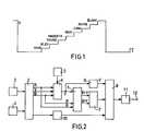
- La figure 1 représente le signal de luminance Y associé à une mire de barres de couleurs transmise en télévision.
- La figure 2 représente un schéma synoptique simplifié d'un jeu vidéo muni de la commande de modification du matriçage de signaux R, V, B selon l'invention.
- Les figures 3 et 4 représentent deux modes différents de réalisation de la commande de modification du matriçage selon l'invention.
- FIG. 1 represents the luminance signal Y associated with a test pattern of color bars transmitted on television.
- FIG. 2 represents a simplified block diagram of a video game provided with the command to modify the matrixing of R, G, B signals according to the invention.
- Figures 3 and 4 show two different embodiments of the matrix modification control according to the invention.
Sur la figure 1, l'amplitude du signal de luminance pour les différentes barres de couleurs est conditionnée par un matriçage des signaux R, V, B, selon la relation suivante: Y (luminance) = 0,30 R+0,59 V +0,11 B.In FIG. 1, the amplitude of the luminance signal for the different color bars is conditioned by a matrixing of the signals R, G, B, according to the following relation: Y (luminance) = 0.30 R + 0.59 V +0.11 B.
On peut voir dans ces conditions que deux couleurs très contrastées pour l'oeil, telles que le bleu et le rouge, se traduisent en noir et blanc par deux gris très voisins; pour peu que les tolérances de matriçage du générateur jouent dans des sens défavorables, ces deux gris seront pratiquement impossibles à différencier.We can see under these conditions that two very contrasting colors for the eye, such as blue and red, translate into black and white by two very close grays; provided that the stamping tolerances of the generator play in unfavorable directions, these two grays will be practically impossible to differentiate.
Par contre, si l'on augmente par exemple la proportion de rouge par rapport au bleu dans le signal de luminance, les deux gris correspondants seront alors aisément discernables.On the other hand, if one increases for example the proportion of red compared to blue in the luminance signal, the two corresponding grays will then be easily discernible.
Sur la figure 2, un circuit 1 d'élaboration de signaux de jeu comporte deux entrées reliées à deux commandes manuelles de jeu 2 et 3, trois sorties de signaux numériques de jeu R, V, B, et une sortie de signaux de synchronisation.In FIG. 2, a circuit 1 for developing game signals has two inputs connected to two
Les signaux numériques R, V, B sont appliqués aux entrées d'un réseau résistif de matriçage 4 muni d'une sortie de signal de luminance Y.The digital signals R, G, B are applied to the inputs of a resistive matrix array 4 provided with a luminance signal output Y.
Le réseau de matriçage 4 comporte une commande manuelle 5 de modification des rapports respectifs de signaux RVB dans le signal de luminance Y.The matrix array 4 includes a
Les entrées d'un second réseau matriciel 6 sont connectées à la sortie Y de la matrice 4, et aux sorties R et B du circuit 1. Le réseau 6 possède deux sorties de signaux de différence de couleurs R-Y et B-Y reliées aux entrées d'un circuit de codage 7.The inputs of a
Les trois entrées d'un circuit mélangeur 8 sont respectivement connectées à la sortie d'un circuit 9 d'adaptation du signal de luminance (par exemple une ligne à retard), à la sortie «chrominance» du circuit de codage 7, et à la sortie d'un circuit 10 de mise en forme des signaux de synchronisation issus du circuit 1.The three inputs of a mixer circuit 8 are respectively connected to the output of a circuit 9 for adapting the luminance signal (for example a delay line), to the “chrominance” output of the coding circuit 7, and to the output of a
La sortie «vidéo-composite» du circuit mélangeur 8 est reliée à l'entrée de modulation d'un générateur 11 VHF ou UHF muni d'une sortie «antenne» 12.The “video-composite” output of the mixer circuit 8 is connected to the modulation input of a VHF or
Dans le générateur représenté figure 2, où une éventuelle voie «son» n'a past été représentée, la modification de l'équilibre du signal de luminance Y au moyen de la commande 5 se retrouve dans le signal vidéo composite issu du circuit 8; le circuit de codage 7 traite les signaux R-Y et B-Y suivant les normes SECAM, PAL ou NTSC en accord avec le téléviseur couleur utilisé.In the generator shown in FIG. 2, where a possible “sound” channel has not been shown, the modification of the balance of the luminance signal Y by means of the
Il est à noter que le schéma synoptique de la figure 2 s'applique tout aussi bien à un micro-ordinateur, le circuit 1 devenant l'unité de traitement et les commandes 2 et 3 un clavier et une mémoire à disque par exemple.It should be noted that the block diagram of FIG. 2 applies equally well to a microcomputer, the circuit 1 becoming the processing unit and the
Egalement de façon non représentée, la sortie du circuit mélangeur 8 est munie d'une borne destinée à être raccordée à l'entrée «vidéo-composite» des téléviseurs pourvus d'une prise «péritélévision».Also not shown, the output of the mixer circuit 8 is provided with a terminal intended to be connected to the “video-composite” input of televisions provided with a “SCART” socket.
La figure 3 montre une première forme de réalisation de la commande de modification des proportions des signaux R, V, B dans le signal de luminance Y; le réseau de matriçage comporte quatre résistances fixes 13, 14, 15 et 16 et un potentiomètre 20 disposé entre les résistances 13 et 15, le curseur de celui-ci étant relié au point commun des résistances 14 et 16. La manoeuvre du potentiomètre 20 fait varier en sens inverse les proportions respectives des niveaux rouge et bleu dans le signal de luminance, le niveau vert restant sensiblement fixe.FIG. 3 shows a first embodiment of the command to modify the proportions of the signals R, G, B in the luminance signal Y; the matrixing network comprises four
La repérage du rapport normal «couleur» peut se faire en munissant le potentiomètre, soit d'un index de repérage, soit d'un «cran» de positionnement à mi-course; dans ce dernier cas, la valeur de la résistance série dans chaque branche sera choisie de façon à donner la résistance totale correspondant au matriçage normal «couleur».The normal “color” ratio can be identified by providing the potentiometer with either a registration index or a mid-range positioning “notch”; in the latter case, the value of the series resistance in each branch will be chosen so as to give the total resistance corresponding to the normal "color" matrixing.
Sur la figure 4 dont les références sont communes avec celles de la figure 3, le schéma du réseau de matriçage correspond à celui de la figure 3 auquel a été adjoint un inverseur 26 commutant l'une des branches (13, 23 par exemple) du réseau matriciel et le curseur du potentiomètre (20). Deux résistances fixes 23, 25 sont respectivement dispoées en série avec les résistances 13 et 15.In FIG. 4, the references of which are common with those of FIG. 3, the diagram of the matrixing network corresponds to that of FIG. 3 to which has been added an
L'inverseur 26 est représenté en position «noir et blanc». En position «couleur», la résistance 23 disposée en série avec la résistance 13 rétablit la matriçage normal.The
Claims (3)
Applications Claiming Priority (2)
| Application Number | Priority Date | Filing Date | Title |
|---|---|---|---|
| FR8110767 | 1981-06-01 | ||
| FR8110767AFR2506623A1 (en) | 1981-06-01 | 1981-06-01 | THREE-COLOR VIDEO SIGNAL GENERATOR, SUCH AS A VIDEO GAME, FOR USE WITH A MONOCHROME IMAGE REPRODUCER |
Publications (2)
| Publication Number | Publication Date |
|---|---|
| EP0066925A1 EP0066925A1 (en) | 1982-12-15 |
| EP0066925B1true EP0066925B1 (en) | 1985-09-04 |
Family
ID=9259040
Family Applications (1)
| Application Number | Title | Priority Date | Filing Date |
|---|---|---|---|
| EP82200646AExpiredEP0066925B1 (en) | 1981-06-01 | 1982-05-27 | Trichromatic video signals generator, such as a video game, utilizable with a monochrome picture reproducer |
Country Status (5)
| Country | Link |
|---|---|
| US (1) | US4481529A (en) |
| EP (1) | EP0066925B1 (en) |
| JP (1) | JPS583386A (en) |
| DE (1) | DE3266016D1 (en) |
| FR (1) | FR2506623A1 (en) |
Families Citing this family (39)
| Publication number | Priority date | Publication date | Assignee | Title |
|---|---|---|---|---|
| FR2544946B1 (en)* | 1983-04-20 | 1987-02-13 | Matra | OSCILLATOR FREQUENCY MODULE AND TELEVISION ENCODER INCORPORATING SUCH AN OSCILLATOR |
| JPS6068774U (en)* | 1983-10-17 | 1985-05-15 | 株式会社東芝 | Retrace signal mixing circuit |
| US4590511A (en)* | 1984-01-03 | 1986-05-20 | Honeywell Inc. | Circuit for converting the phase encoded hue information of a quadrature modulated color subcarrier into distinct analog voltage levels |
| FR2558026B1 (en)* | 1984-01-06 | 1986-04-11 | Thomson Csf | SYSTEM FOR PROCESSING VIDEO SIGNALS OF IMAGES FOR MONOCHROME VIEWING |
| US4703318A (en)* | 1984-03-30 | 1987-10-27 | Wang Laboratories, Inc. | Character-based monochromatic representation of color images |
| US4688031A (en)* | 1984-03-30 | 1987-08-18 | Wang Laboratories, Inc. | Monochromatic representation of color images |
| US4631692A (en)* | 1984-09-21 | 1986-12-23 | Video-7 Incorporated | RGB interface |
| GB8431038D0 (en)* | 1984-12-07 | 1985-01-16 | Ncr Co | Circuit means |
| JPS61198275A (en)* | 1985-02-28 | 1986-09-02 | 株式会社東芝 | Monochrome gradation display device |
| JPS61213896A (en)* | 1985-03-19 | 1986-09-22 | 株式会社 アスキ− | Display controller |
| US4827255A (en)* | 1985-05-31 | 1989-05-02 | Ascii Corporation | Display control system which produces varying patterns to reduce flickering |
| US4868883A (en)* | 1985-12-30 | 1989-09-19 | Exxon Production Research Company | Analysis of thin section images |
| US4725879A (en)* | 1987-03-27 | 1988-02-16 | Honeywell Inc. | Chroma responsive inspection apparatus selectively producing analog voltage levels based on the luminance, the phase of the chrominance subcarrier, or the amplitude of the chrominance subcarrier |
| US4847604A (en)* | 1987-08-27 | 1989-07-11 | Doyle Michael D | Method and apparatus for identifying features of an image on a video display |
| US5245327A (en)* | 1988-01-15 | 1993-09-14 | Chips And Technologies, Incorporated | Color to monochrome conversion |
| WO1989006851A1 (en)* | 1988-01-15 | 1989-07-27 | Chips And Technologies, Inc. | Color to monochrome conversion |
| US4977398A (en)* | 1988-01-15 | 1990-12-11 | Chips And Technologies, Incorporated | Color to monochrome conversion |
| JP2769345B2 (en)* | 1989-02-21 | 1998-06-25 | 三菱電機株式会社 | Display control device |
| US5150199A (en)* | 1990-01-02 | 1992-09-22 | Megatronics, Inc. | Method for correlating color measuring scales |
| GB9001429D0 (en)* | 1990-01-22 | 1990-03-21 | British Broadcasting Corp | Improvements in television |
| JPH04182696A (en)* | 1990-11-17 | 1992-06-30 | Nintendo Co Ltd | Image processor |
| JPH04291591A (en)* | 1991-03-19 | 1992-10-15 | Sony Corp | color display device |
| US5408249A (en)* | 1993-11-24 | 1995-04-18 | Radiation Measurements, Inc. | Bit extension adapter for computer graphics |
| US6315669B1 (en)* | 1998-05-27 | 2001-11-13 | Nintendo Co., Ltd. | Portable color display game machine and storage medium for the same |
| US7050064B2 (en)* | 1999-11-24 | 2006-05-23 | Nintendo Co., Ltd. | Method and apparatus for displaying higher color resolution on a hand-held LCD device |
| US6373462B1 (en) | 1999-12-07 | 2002-04-16 | Nintendo Co., Ltd. | Method and apparatus for displaying higher color resolution on a hand-held LCD device |
| US7445551B1 (en) | 2000-05-24 | 2008-11-04 | Nintendo Co., Ltd. | Memory for video game system and emulator using the memory |
| US6810463B2 (en) | 2000-05-24 | 2004-10-26 | Nintendo Co., Ltd. | Gaming machine that is usable with different game cartridge types |
| US8157654B2 (en) | 2000-11-28 | 2012-04-17 | Nintendo Co., Ltd. | Hand-held video game platform emulation |
| US6672963B1 (en) | 2000-09-18 | 2004-01-06 | Nintendo Co., Ltd. | Software implementation of a handheld video game hardware platform |
| US6884171B2 (en) | 2000-09-18 | 2005-04-26 | Nintendo Co., Ltd. | Video game distribution network |
| US7057668B2 (en)* | 2002-04-19 | 2006-06-06 | Kopin Corporation | Color/mono switched display |
| GB2396507B (en)* | 2002-12-20 | 2005-07-06 | Motorola Inc | A visual display device and a method of generating a visual display signal therefor |
| US7771280B2 (en)* | 2004-03-31 | 2010-08-10 | Nintendo Co., Ltd. | Game console connector and emulator for the game console |
| US8016681B2 (en)* | 2004-03-31 | 2011-09-13 | Nintendo Co., Ltd. | Memory card for a game console |
| US8267780B2 (en) | 2004-03-31 | 2012-09-18 | Nintendo Co., Ltd. | Game console and memory card |
| US11278793B2 (en) | 2004-03-31 | 2022-03-22 | Nintendo Co., Ltd. | Game console |
| US7837558B2 (en)* | 2004-03-31 | 2010-11-23 | Nintendo Co., Ltd. | Game console and emulator for the game console |
| WO2006080488A1 (en) | 2005-01-31 | 2006-08-03 | Komatsu Ltd. | Working vehicle with tilt floor |
Family Cites Families (9)
| Publication number | Priority date | Publication date | Assignee | Title |
|---|---|---|---|---|
| CA956025A (en)* | 1971-10-26 | 1974-10-08 | Zenith Radio Corporation | Matrix amplifier network with novel d-c set-up arrangement |
| JPS4929933A (en)* | 1972-07-19 | 1974-03-16 | ||
| US4121283A (en)* | 1977-01-17 | 1978-10-17 | Cromemco Inc. | Interface device for encoding a digital image for a CRT display |
| JPS5845230B2 (en)* | 1977-05-20 | 1983-10-07 | 松下電器産業株式会社 | Color control device for color television receivers |
| JPS5477528A (en)* | 1977-12-02 | 1979-06-21 | Mitsubishi Electric Corp | Video amplifier circuit |
| NL7801690A (en)* | 1978-02-15 | 1979-08-17 | Philips Nv | MONOCHROME IMAGE DISPLAY DEVICE. |
| US4200867A (en)* | 1978-04-03 | 1980-04-29 | Hill Elmer D | System and method for painting images by synthetic color signal generation and control |
| US4229760A (en)* | 1978-05-26 | 1980-10-21 | Rca Corporation | Video games color synthesis |
| JPS5639689A (en)* | 1979-09-06 | 1981-04-15 | Aiwa Co Ltd | Luminance signal synthesizer |
- 1981
- 1981-06-01FRFR8110767Apatent/FR2506623A1/enactiveGranted
- 1982
- 1982-05-27EPEP82200646Apatent/EP0066925B1/ennot_activeExpired
- 1982-05-27DEDE8282200646Tpatent/DE3266016D1/ennot_activeExpired
- 1982-05-27USUS06/382,736patent/US4481529A/ennot_activeExpired - Fee Related
- 1982-05-31JPJP57092952Apatent/JPS583386A/enactivePending
Non-Patent Citations (2)
| Title |
|---|
| WIRELESS WORLD, vol.81, no.1480, décembre 1975, Londres (GB) J.F. DANIELS: "Wireless world teletext decoder", pages 563-566* |
| WIRELESS WORLD, vol.82, no.1486, juin 1976, Londres (GB) J.F. DANIELS: "Wireless world teletext decoder", pages 53-56* |
Also Published As
| Publication number | Publication date |
|---|---|
| DE3266016D1 (en) | 1985-10-10 |
| FR2506623A1 (en) | 1982-12-03 |
| US4481529A (en) | 1984-11-06 |
| FR2506623B1 (en) | 1984-10-19 |
| JPS583386A (en) | 1983-01-10 |
| EP0066925A1 (en) | 1982-12-15 |
Similar Documents
| Publication | Publication Date | Title |
|---|---|---|
| EP0066925B1 (en) | Trichromatic video signals generator, such as a video game, utilizable with a monochrome picture reproducer | |
| FR2524235A1 (en) | SPACE TRANSFORMATION SYSTEM COMPRISING A SIGNAL SIGNAL GENERATOR | |
| FR2546643A1 (en) | DEVICE FOR PROCESSING SIGNALS, ESPECIALLY CHROMINANCE SIGNALS OF A COLOR TELEVISION | |
| EP0564497A1 (en) | Television receiver | |
| US6313883B1 (en) | Method and apparatus for finite local enhancement of a video display reproduction of images | |
| KR920004106B1 (en) | TV signal processing system | |
| JPH0246086A (en) | Color correcting circuit | |
| US5896121A (en) | Data-dependent color display for vectorscopes | |
| JPH04227190A (en) | Dynamic color temperature automatic adjustment method and device for color television device | |
| EP0620692B1 (en) | Tint detection circuit | |
| EP0645934A1 (en) | Television receiver with a device for selecting from a plurality of signal sources | |
| Hubel | Color image quality in digital cameras | |
| EP1232653B1 (en) | Method and apparatus for enhancing green contrast of a color video signal | |
| JP3421864B2 (en) | Video camera | |
| Brill et al. | Comparison of reference‐white standards for video display units | |
| TWI227630B (en) | A method of inter-frame Y/C separation | |
| JP3117989B2 (en) | Color image processing equipment | |
| JPH0148715B2 (en) | ||
| KR100771618B1 (en) | Color adjustment device and method | |
| FR2551296A1 (en) | APPARATUS FOR PROCESSING DIGITAL SIGNALS, WHICH CAN BE USED BY A TELEVISION RECEIVER | |
| JP2001112020A (en) | Light source selection and color digital imaging device ricoverable after shot | |
| US7046305B1 (en) | Method and apparatus for enhancing green contrast of a color video signal | |
| JPH05211653A (en) | Digital camera | |
| JP2000354252A (en) | Hue discrimination circuit | |
| JPS6147046A (en) | Device for partially stressing electron-microscopic images |
Legal Events
| Date | Code | Title | Description |
|---|---|---|---|
| PUAI | Public reference made under article 153(3) epc to a published international application that has entered the european phase | Free format text:ORIGINAL CODE: 0009012 | |
| 17P | Request for examination filed | Effective date:19820527 | |
| AK | Designated contracting states | Designated state(s):DE FR GB | |
| GRAA | (expected) grant | Free format text:ORIGINAL CODE: 0009210 | |
| AK | Designated contracting states | Designated state(s):DE FR GB | |
| REF | Corresponds to: | Ref document number:3266016 Country of ref document:DE Date of ref document:19851010 | |
| PLBE | No opposition filed within time limit | Free format text:ORIGINAL CODE: 0009261 | |
| STAA | Information on the status of an ep patent application or granted ep patent | Free format text:STATUS: NO OPPOSITION FILED WITHIN TIME LIMIT | |
| 26N | No opposition filed | ||
| REG | Reference to a national code | Ref country code:FR Ref legal event code:TP | |
| PG25 | Lapsed in a contracting state [announced via postgrant information from national office to epo] | Ref country code:GB Effective date:19890527 | |
| REG | Reference to a national code | Ref country code:FR Ref legal event code:CD | |
| GBPC | Gb: european patent ceased through non-payment of renewal fee | ||
| PG25 | Lapsed in a contracting state [announced via postgrant information from national office to epo] | Ref country code:FR Free format text:LAPSE BECAUSE OF NON-PAYMENT OF DUE FEES Effective date:19900131 | |
| PG25 | Lapsed in a contracting state [announced via postgrant information from national office to epo] | Ref country code:DE Effective date:19900201 | |
| REG | Reference to a national code | Ref country code:FR Ref legal event code:ST |