EP0066393B1 - Multiarm robot - Google Patents
Multiarm robotDownload PDFInfo
- Publication number
- EP0066393B1 EP0066393B1EP82302465AEP82302465AEP0066393B1EP 0066393 B1EP0066393 B1EP 0066393B1EP 82302465 AEP82302465 AEP 82302465AEP 82302465 AEP82302465 AEP 82302465AEP 0066393 B1EP0066393 B1EP 0066393B1
- Authority
- EP
- European Patent Office
- Prior art keywords
- arms
- workhead
- arm
- multiarm
- location
- Prior art date
- Legal status (The legal status is an assumption and is not a legal conclusion. Google has not performed a legal analysis and makes no representation as to the accuracy of the status listed.)
- Expired
Links
Images


Classifications
- B—PERFORMING OPERATIONS; TRANSPORTING
- B25—HAND TOOLS; PORTABLE POWER-DRIVEN TOOLS; MANIPULATORS
- B25J—MANIPULATORS; CHAMBERS PROVIDED WITH MANIPULATION DEVICES
- B25J17/00—Joints
- B25J17/02—Wrist joints
- B25J17/0258—Two-dimensional joints
- B25J17/0266—Two-dimensional joints comprising more than two actuating or connecting rods
- B—PERFORMING OPERATIONS; TRANSPORTING
- B25—HAND TOOLS; PORTABLE POWER-DRIVEN TOOLS; MANIPULATORS
- B25J—MANIPULATORS; CHAMBERS PROVIDED WITH MANIPULATION DEVICES
- B25J17/00—Joints
- B25J17/02—Wrist joints
- B25J17/0258—Two-dimensional joints
- B25J17/0275—Universal joints, e.g. Hooke, Cardan, ball joints
- Y—GENERAL TAGGING OF NEW TECHNOLOGICAL DEVELOPMENTS; GENERAL TAGGING OF CROSS-SECTIONAL TECHNOLOGIES SPANNING OVER SEVERAL SECTIONS OF THE IPC; TECHNICAL SUBJECTS COVERED BY FORMER USPC CROSS-REFERENCE ART COLLECTIONS [XRACs] AND DIGESTS
- Y10—TECHNICAL SUBJECTS COVERED BY FORMER USPC
- Y10T—TECHNICAL SUBJECTS COVERED BY FORMER US CLASSIFICATION
- Y10T74/00—Machine element or mechanism
- Y10T74/18—Mechanical movements
- Y10T74/18568—Reciprocating or oscillating to or from alternating rotary
- Y10T74/18576—Reciprocating or oscillating to or from alternating rotary including screw and nut
- Y10T74/18624—Plural inputs, single output
Definitions
- This inventionpertains generally to structural arrangements for a robot, and more particularly to structural arrangements for robots of the type which include a plurality of independent arms which converge to a workhead end.
- This inventionprovides a robot structure that incorporates a concept of best use of the strength of materials in a way that the weight to payload ratio is in the order of one to one. Consequently, the operating motor sizes can be significantly smallerthan in prior art. Additionally, other advantages result from the inventive arrangement with respect to speed and accuracy of operation.
- Robots having a plurality of arms substantially converging to a workhead endhave advantages over other conventional types; however, such robots should also be advantageously endowed with sensitive fast-responsive movements.
- Control movements of robotic arms using hydraulic cylinders (with pistons) or other linear movement actuating mechanismsare known in the art; such prior art arrangements howeversufferfrom disadvantages such as lack of fast response and lack of accuracy of response.
- a tool-positioning apparatuscomprising three primary arms, each pivoted to swing about an axis, three rotary differential electricl motors for controlling the swinging movement of the said arms, respectively, three secondary arms, each pivotally connected at one end with one end of said primary arms, and a tool carried by said secondary arms to which the other ends of said secondary arms are connected.
- the present inventionconsists in a multiarm manipulatorfor automatically and accurately positioning a workhead which is connected to be controlled by said multiarm manipulator, comprising a support structure, at least three substantially convergent arms having longitudinal axes intersecting at a point and having their remote end portions hingedly connected at a location which is at least relatively close to the point of intersection of the axes of the three arms, said location being adjacent the workhead connected to said three arms, and having their proximate end portions carried in gimbaled relation from said support structure at spaced apart locations defining points of a triangle, driving means for selectively driving each arm axially and independently with respectto said support structure to move said workhead to different locations, said driving means being carried by said support structure and being fixed in location at said support structure, each arm being rigid for its length in use in the sense that no part of the arm is hingedly connected to another part so that the forces derived from the payload weight and movement subject said arms primarily only to compression or tension, said driving means comprising a rotatable nut having inside
- the robotincludes a support structure with three arms having their first end portions hingedly connected at a location which is at least relatively close to the point of intersection of the axis of the three arms, this location being adjacent the workhead.
- the armshave their proximate end portions carried in gimbaled relation from the support structure at spaced apart locations thereat which together define the points of a triangle.
- the support structurecarries driving means which are fixed in location at the support structure, the driving means serving to drive each arm axially and independently to move the workhead to different positions, and each arm is rigid for its length in the sense that no part of the arm is hingedly connected to another part.
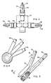
- the basic apparatusincludes a support plate 10, three arms 12, 14 and 16, and separate and independent driving means 12a, 14a, and 16a, respectively, each arranged for driving its respective arm axially and independently.
- Each armmay be considered to be comprised of a proximate end portion as at 12b, and a remote or distal end portion as at 12c, corresponding letters being applied in Figure 1 to the corresponding parts of the other two arms.
- the distal end portions 12c, 14c, and 16care hingedly connected together at a location generally designated 18, this location in Figure 1 being at the point of intersection of the axes of the three arms as will be explained in more detail in connection with Figures 3 and 4.
- proximate end portions 12b, 14b, and 16bare carried from the support structure 10 in gimbaled relation therewith and, as may best be seen in Figure 2, at spaced apart locations which together define the points of a triangle.
- One particular arrangement for obtaining the gimbal mountingswill be explained in more detail in connection with Figures 6 and 7 hereinafter.
- a workheadis carried adjacent the hinge connection and maytaketheform of any of the various devices such as the diagrammatically illustrated exemplary gripper 20.
- the workheadhas additional motion imparted to it beyond that of the simple locational motion provided by the three arms; the additional motion is through one or more flexible cables 22 which, in one preferred embodiment, pass into the hollow arms closely adjacentthe hinge and extend therethrough to the extreme end of the proximate end of the arms to a device as at 24 for imparting motion to the cable.
- the workheadmay not only be positioned in a desired location, but may also perhaps be swiveled or tilted depending upon the job requirements of the workhead.
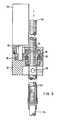
- FIG. 5One example of a drive arrangement for a given arm, in this example the arm being 12, is illustrated in Figure 5.
- the proximate end portion of the armcomprises the exteriorly threaded screw 12c which extends through an opening 32 in the drive block 34.
- the drive blockincludes an interior chamber 36 in which an interiorly threaded gear 38 is situated with its teeth meshing with the exterior threads of the distal end portion 12c.
- the gear 38is in turn driven by gear 40 fixed to the shaft 42 of a servomotor 12a.
- the driving gear 38is replaced by a recirculating ball in an arrangement generally similar to that shown in U.S. Patent 3,161,074.
- FIG. 5Details of the rigid joint between the proximate and distal ends of an arm may also be seen in Figure 5.
- the upper end of the distal portion 12cis turned into the lower end of the proximate portion 12b.
- a dust cover in the form of an outer tube 12dcan receive the distal portion in telescopic relation. In some cases it may be desirable to use an expandable-retractable flexible cover or a bellows type cover.
- the motorsare preferably provided with an integral tachometer and an encoder or resolver.
- the pitch of the lead screw and the encoder or resolverare chosen to suit the particular application. As an example, a five pitch per inch lead screw and a 200 pulse per revolution encoder will have a resolution of 0.001 in. (2.54 E-5 m) on axial movement of the lead screw. A 1000 pulse per revolution encoder will increase the resolution five times for accurate assembly work. A typical moderate motor speed of 2000 rpm will result in axial movement at the rate of 400 inches (10.16 m) per minute. At a subtended angle of 30° between lead screws, the lateral speed is about four times the lead screw axial speed, while the resolution is four times worse than the axial resolution. In other words, if the lead screw resolution is 0.001 inch (2.54 E-5 m) the lateral resolution is 0.004 inch (1.016 E-4 m) which is a value which is acceptable for many industrial applications.
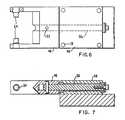
- a yoke member 46is supported from block 48 by a pin 50 in aligned bores of the two members.
- the pinis fixed as at 52 to the yoke member 46 and is free to rotate in the bore of the block 48 so that the yoke can rotate in one plane normal to the axis of the pin.
- the arms of the yokeare provided with inwardly projecting axles 54 which, in the assembly of the drive block 34 to the yoke, project into oppositely disposed bores 56 ( Figure 5) to journal the drive block for rotation in a plane.
- the block 48in turn is affixed to the support plate 10 ( Figure 2) by fasteners through the four corner holes 58 in the block 48.
- FIG 8a five arm robotic manipulator is illustrated. Basically the same three arm arrangement as in Figure 1 is used to positionally locate the workhead plate 60 while the two additional arms are used to tilt the workhead plate 60 around a horizontal axis passing through the joint between the worked and locational arms.
- the arms 62, 64 and 66correspond to the three locating arms 12-16 of Figure 1, the arms 64 and 66 being those which are joined in a scissors joint relationship. It is noted that the hinged joint of the three arms at 68 does not correspond with the joint 18 of Figure 1, the resulting joint 68 being slightly offset from the location where the axes of the three arms meet and the location of the hinged joint. This is considered to be slightly less preferable than an arrangement as shown in Figure 1 since, to the degree the intersection of the axes of the arms is displaced from the hinged joint, there is a corresponding increase in the degree to which a bending movement can be imposed upon the arm having its axis missing the joint. However, for many purposes the illustrated joint arrangement is entirely adequate.
- the two additional arms 70 and 72are connected to the work head piece 60 in rotating and pivotally fashion near one and the other opposite top corners of the plate 60. In other respects the arms and their respective drive means are essentially the same as those described in Figure 1.
- the working device schematically shown in Figure 8 and mounted to the workhead plate 60is intended to represent a welding device 74 which can conveniently be manipulated by a robot that is shown in Figure 8 in view of requirements at times to not only properly locate and move the welding head but also to tilt it.
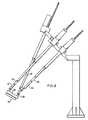
- Figure 9illustrates an arrangement in which a manipulator is not only furnished with five axially movable arms, but additionally is provided with a sixth drive element for effecting a swivel movement about an axis normal to the plane of the workpiece.
- the arms corresponding to those of Figure 8are identically numbered with the sixth drive element being identified by numeral 76.
- the work deviceis a gripper 78 which is carried for rotation within workhead 80 through a bearing arrangement.
- the sixth drive element 76is connected to the gripper 78 through the workhead so that rotation of the element 76 will result in rotation of the gripper 78 about its center axis.
- the three arms 62, 64 and 66control the locational position of the workhead, with the two arms 70 and 72 providing for movement in a tilting position about one axis and a swiveling movement about another axis.
- the dashed line representation of the movable parts of the robotis intended to illustrate one of many other positions to which it may be moved.
- the proximate end portion of the sixth arm 76has longitudinally extending exterior splines, rather than helical threads as do the other arms.
- An interiorly splined nut in the drivepermits the splined rod to move axially to accommodate the changing portion of the workhead by the axial movement of the other arms; by rotating the interiorly splined nut as called for the gripper is rotated.
- the drive motorsare programmed or otherwise controlled in accordance with the particular application in which the automatic robot is employed. Regardless of the form however, it will be appreciated that there are numerous advantages associated with the inventive robot as contrasted to the conventional robots.
- the driving means for various armsis supported by the support plate so that the arms themselves are essentially the only moving parts of the structure and accordingly the moving structure is relatively light weight. There is very little bending moment in the structure, so that the forces which derive from the payload weight and workhead movement subject the arms primarly only to compression or tension.
- the driving meansbeing located remotely on the stationary support part of the device, they are away from any hostile environment in which the workhead may be required to intrude. Since the arrangement can be maintained essentially the same regardless of size, the device of the invention can be scaled up or down over a wide range of payload, working space, and performance capabilities.
Landscapes
- Engineering & Computer Science (AREA)
- Robotics (AREA)
- Mechanical Engineering (AREA)
- Manipulator (AREA)
Description
- This invention pertains generally to structural arrangements for a robot, and more particularly to structural arrangements for robots of the type which include a plurality of independent arms which converge to a workhead end.
- Many conventional industrial robots which are known in prior art have a general design arrangement in which a vertical post supports a horizontally extending boom or arm having a workhead at the end of the arm. As such, the arm is subject to a bending moment. To resist bending, the structural members of the arm are designed with a relatively high degree of rigidity which makes the arm relatively heavy. Accordingly, the structure supporting the arm is relatively heavier. As an example, a robot arm intended to operate with a payload of, say, 100 pounds (45 kg) will have a structure weighing perhaps over 1000 pounds (454 kg). Thus the arm may have a weight of ten times the payload. Consequently, the motors required for operating such conventional robots are necessarily large and are expensive.
- This invention provides a robot structure that incorporates a concept of best use of the strength of materials in a way that the weight to payload ratio is in the order of one to one. Consequently, the operating motor sizes can be significantly smallerthan in prior art. Additionally, other advantages result from the inventive arrangement with respect to speed and accuracy of operation.
- Robots having a plurality of arms substantially converging to a workhead end have advantages over other conventional types; however, such robots should also be advantageously endowed with sensitive fast-responsive movements. Control movements of robotic arms using hydraulic cylinders (with pistons) or other linear movement actuating mechanisms are known in the art; such prior art arrangements howeversufferfrom disadvantages such as lack of fast response and lack of accuracy of response.
- In US-A-2 286 571 there is described and claimed a tool-positioning apparatus comprising three primary arms, each pivoted to swing about an axis, three rotary differential electricl motors for controlling the swinging movement of the said arms, respectively, three secondary arms, each pivotally connected at one end with one end of said primary arms, and a tool carried by said secondary arms to which the other ends of said secondary arms are connected.
- The present invention consists in a multiarm manipulatorfor automatically and accurately positioning a workhead which is connected to be controlled by said multiarm manipulator, comprising a support structure, at least three substantially convergent arms having longitudinal axes intersecting at a point and having their remote end portions hingedly connected at a location which is at least relatively close to the point of intersection of the axes of the three arms, said location being adjacent the workhead connected to said three arms, and having their proximate end portions carried in gimbaled relation from said support structure at spaced apart locations defining points of a triangle, driving means for selectively driving each arm axially and independently with respectto said support structure to move said workhead to different locations, said driving means being carried by said support structure and being fixed in location at said support structure, each arm being rigid for its length in use in the sense that no part of the arm is hingedly connected to another part so that the forces derived from the payload weight and movement subject said arms primarily only to compression or tension, said driving means comprising a rotatable nut having inside threads, a lead screw engages inside the rotatable nut, and a motor coupled to rotate said rotatable nut.
- In accordance with one embodiment of the invention the robot includes a support structure with three arms having their first end portions hingedly connected at a location which is at least relatively close to the point of intersection of the axis of the three arms, this location being adjacent the workhead. The arms have their proximate end portions carried in gimbaled relation from the support structure at spaced apart locations thereat which together define the points of a triangle. The support structure carries driving means which are fixed in location at the support structure, the driving means serving to drive each arm axially and independently to move the workhead to different positions, and each arm is rigid for its length in the sense that no part of the arm is hingedly connected to another part. Thus the forces derived from the payload weight subject the arms primarily only to compression or tension.
- The invention may be understood in greater detail from the following description of a preferred embodiment given by way of example and to be studied in conjunction with the accompanying drawing wherein:
- Figure 1 is an elevation view of a three arm robot according to an embodiment of the invention;
- Figure 2 is a face view of the support end of the robot of Figure 1;
- Figure 3 is a partly broken and fragmentary view, enlarged relative to Figure 1, of a preferred hinging arrangement at the remote or distal ends of the arms;
- Figure 4 is a face view of the structure shown in Figure 3;
- Figure 5 is a partly broken and fragmentary view in vertical cross-section of the arrangement for driving one arm;
- Figure 6 is a plan view of one form of a gimbaling bracket structure;
- Figure 7 is an elevation view of the bracket of Figure 6;
- Figure 8 is an elevation view of an embodiment of the invention in which five arms are used, and the hinged connection arrangement of the three arms is different from that shown in Figures 1-4;
- Figure 9 is an elevation view of a six arm robot in both a solid line and a dash line position; and
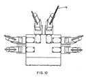
- Figure 10 is a face of the support end of the Figure 9 device.
- Referring to Figures 1 and 2, the basic apparatus includes a
support plate 10, threearms - Each arm may be considered to be comprised of a proximate end portion as at 12b, and a remote or distal end portion as at 12c, corresponding letters being applied in Figure 1 to the corresponding parts of the other two arms. The
distal end portions - The
proximate end portions support structure 10 in gimbaled relation therewith and, as may best be seen in Figure 2, at spaced apart locations which together define the points of a triangle. One particular arrangement for obtaining the gimbal mountings will be explained in more detail in connection with Figures 6 and 7 hereinafter. - A workhead is carried adjacent the hinge connection and maytaketheform of any of the various devices such as the diagrammatically illustrated
exemplary gripper 20. In one preferred form of the invention the workhead has additional motion imparted to it beyond that of the simple locational motion provided by the three arms; the additional motion is through one or moreflexible cables 22 which, in one preferred embodiment, pass into the hollow arms closely adjacentthe hinge and extend therethrough to the extreme end of the proximate end of the arms to a device as at 24 for imparting motion to the cable. Thus the workhead may not only be positioned in a desired location, but may also perhaps be swiveled or tilted depending upon the job requirements of the workhead. - In Figures 3 and 4 the currently preferred hinge connection arrangement is illustrated, the essence of this arrangement being thatthe axes of the three arms meet at a common point which is the center of the hinged connection. As may be thereseen, the two
lower arms spherical bearing 26 while thebearing shaft 28 is fixed to anoffset end portion 30 of the extreme distal end of thearm 12. The intersection of the axes of the arms at the center of the bearing is illustrated by the center lines. As should be apparent from the drawing, each of the arms may be angularly displaced with respect to each of the other arms through selective axial movement of the various arms. - One example of a drive arrangement for a given arm, in this example the arm being 12, is illustrated in Figure 5. The proximate end portion of the arm comprises the exteriorly threaded
screw 12c which extends through anopening 32 in thedrive block 34. The drive block includes aninterior chamber 36 in which an interiorly threadedgear 38 is situated with its teeth meshing with the exterior threads of thedistal end portion 12c. Thegear 38 is in turn driven bygear 40 fixed to theshaft 42 of a servomotor 12a. In another form of drive arrangement thedriving gear 38 is replaced by a recirculating ball in an arrangement generally similar to that shown in U.S. Patent 3,161,074. - Details of the rigid joint between the proximate and distal ends of an arm may also be seen in Figure 5. The upper end of the
distal portion 12c is turned into the lower end of theproximate portion 12b. A dust cover in the form of an outer tube 12d can receive the distal portion in telescopic relation. In some cases it may be desirable to use an expandable-retractable flexible cover or a bellows type cover. - As currently contemplated, in the preferred embodiment the motors are preferably provided with an integral tachometer and an encoder or resolver. The pitch of the lead screw and the encoder or resolver are chosen to suit the particular application. As an example, a five pitch per inch lead screw and a 200 pulse per revolution encoder will have a resolution of 0.001 in. (2.54 E-5 m) on axial movement of the lead screw. A 1000 pulse per revolution encoder will increase the resolution five times for accurate assembly work. A typical moderate motor speed of 2000 rpm will result in axial movement at the rate of 400 inches (10.16 m) per minute. At a subtended angle of 30° between lead screws, the lateral speed is about four times the lead screw axial speed, while the resolution is four times worse than the axial resolution. In other words, if the lead screw resolution is 0.001 inch (2.54 E-5 m) the lateral resolution is 0.004 inch (1.016 E-4 m) which is a value which is acceptable for many industrial applications.
- Referring now to Figures 6 and 7, one form of arrangement for mounting the
block 34 in gimbaled relation from thesupport plate 10 is shown. Ayoke member 46 is supported fromblock 48 by apin 50 in aligned bores of the two members. The pin is fixed as at 52 to theyoke member 46 and is free to rotate in the bore of theblock 48 so that the yoke can rotate in one plane normal to the axis of the pin. The arms of the yoke are provided with inwardly projectingaxles 54 which, in the assembly of thedrive block 34 to the yoke, project into oppositely disposed bores 56 (Figure 5) to journal the drive block for rotation in a plane. Theblock 48 in turn is affixed to the support plate 10 (Figure 2) by fasteners through the fourcorner holes 58 in theblock 48. From the foregoing it will be appreciated that the arms as so supported are free to move to various anguler dispositions within the range of limits of the mechanism. - Turning now to Figure 8, a five arm robotic manipulator is illustrated. Basically the same three arm arrangement as in Figure 1 is used to positionally locate the
workhead plate 60 while the two additional arms are used to tilt theworkhead plate 60 around a horizontal axis passing through the joint between the worked and locational arms. - The
arms arms 64 and 66 being those which are joined in a scissors joint relationship. It is noted that the hinged joint of the three arms at 68 does not correspond with the joint 18 of Figure 1, the resulting joint 68 being slightly offset from the location where the axes of the three arms meet and the location of the hinged joint. This is considered to be slightly less preferable than an arrangement as shown in Figure 1 since, to the degree the intersection of the axes of the arms is displaced from the hinged joint, there is a corresponding increase in the degree to which a bending movement can be imposed upon the arm having its axis missing the joint. However, for many purposes the illustrated joint arrangement is entirely adequate. The twoadditional arms work head piece 60 in rotating and pivotally fashion near one and the other opposite top corners of theplate 60. In other respects the arms and their respective drive means are essentially the same as those described in Figure 1. - The working device schematically shown in Figure 8 and mounted to the
workhead plate 60 is intended to represent awelding device 74 which can conveniently be manipulated by a robot that is shown in Figure 8 in view of requirements at times to not only properly locate and move the welding head but also to tilt it. - Figure 9 illustrates an arrangement in which a manipulator is not only furnished with five axially movable arms, but additionally is provided with a sixth drive element for effecting a swivel movement about an axis normal to the plane of the workpiece. In Figure 9 the arms corresponding to those of Figure 8 are identically numbered with the sixth drive element being identified by
numeral 76. In the illustration the work device is agripper 78 which is carried for rotation within workhead 80 through a bearing arrangement. Thesixth drive element 76 is connected to thegripper 78 through the workhead so that rotation of theelement 76 will result in rotation of thegripper 78 about its center axis. As with the manipulator of Figure 8, the threearms arms - It will be seen from the illustrations of the six arm device in Figures 9 and 10 that the proximate end portion of the
sixth arm 76 has longitudinally extending exterior splines, rather than helical threads as do the other arms. An interiorly splined nut in the drive permits the splined rod to move axially to accommodate the changing portion of the workhead by the axial movement of the other arms; by rotating the interiorly splined nut as called for the gripper is rotated. - In the operation of any of the devices illustrated as different embodiments of the invention, it will be appreciated that the drive motors are programmed or otherwise controlled in accordance with the particular application in which the automatic robot is employed. Regardless of the form however, it will be appreciated that there are numerous advantages associated with the inventive robot as contrasted to the conventional robots. The driving means for various arms is supported by the support plate so that the arms themselves are essentially the only moving parts of the structure and accordingly the moving structure is relatively light weight. There is very little bending moment in the structure, so that the forces which derive from the payload weight and workhead movement subject the arms primarly only to compression or tension. With the driving means being located remotely on the stationary support part of the device, they are away from any hostile environment in which the workhead may be required to intrude. Since the arrangement can be maintained essentially the same regardless of size, the device of the invention can be scaled up or down over a wide range of payload, working space, and performance capabilities.
Claims (9)
Applications Claiming Priority (2)
| Application Number | Priority Date | Filing Date | Title |
|---|---|---|---|
| US06/264,154US4407625A (en) | 1981-05-15 | 1981-05-15 | Multi-arm robot |
| US264154 | 1981-05-15 |
Publications (3)
| Publication Number | Publication Date |
|---|---|
| EP0066393A2 EP0066393A2 (en) | 1982-12-08 |
| EP0066393A3 EP0066393A3 (en) | 1983-09-14 |
| EP0066393B1true EP0066393B1 (en) | 1986-09-03 |
Family
ID=23004841
Family Applications (1)
| Application Number | Title | Priority Date | Filing Date |
|---|---|---|---|
| EP82302465AExpiredEP0066393B1 (en) | 1981-05-15 | 1982-05-14 | Multiarm robot |
Country Status (8)
| Country | Link |
|---|---|
| US (1) | US4407625A (en) |
| EP (1) | EP0066393B1 (en) |
| JP (1) | JPS57194887A (en) |
| CA (1) | CA1181113A (en) |
| DE (1) | DE3272993D1 (en) |
| ES (1) | ES512176A0 (en) |
| IE (1) | IE52793B1 (en) |
| ZA (1) | ZA822353B (en) |
Families Citing this family (43)
| Publication number | Priority date | Publication date | Assignee | Title |
|---|---|---|---|---|
| JPS5882154A (en)* | 1981-11-10 | 1983-05-17 | Mitsubishi Electric Corp | Lifting gear for water examination instrument |
| JPS58126090A (en)* | 1982-01-18 | 1983-07-27 | 株式会社神戸製鋼所 | Multi-articulated arm mechanism |
| US4435116A (en) | 1982-05-27 | 1984-03-06 | Deberg Walter H | Robotic manipulator |
| PT77732B (en)* | 1982-12-16 | 1986-03-27 | Cyber Robotics Ltd | Robotic limb |
| JPS59132789U (en)* | 1983-02-25 | 1984-09-05 | 株式会社中村機器エンジニアリング | Device that moves the article gripping mechanism to four locations within the projection plane |
| US4569627A (en)* | 1983-03-10 | 1986-02-11 | Simunovic Sergio N | Robotic manipulator |
| DE3332196C2 (en)* | 1983-09-07 | 1985-08-01 | Hermann Spicher GmbH, 5000 Köln | Device for the automatic removal of objects from containers |
| US4687400A (en)* | 1984-09-07 | 1987-08-18 | Metals, Ltd. | Device for moving objects in a closed container |
| US6477913B1 (en) | 1985-01-22 | 2002-11-12 | Fanuc Robotics North America, Inc. | Electric robot for use in a hazardous location |
| US4984745A (en)* | 1985-01-22 | 1991-01-15 | Gmf Robotics Corporation | Electric robot for use in a hazardous location |
| US4790718A (en)* | 1985-03-27 | 1988-12-13 | The English Electric Company Plc | Manipulators |
| SE452279B (en)* | 1985-05-10 | 1987-11-23 | Neos Products Hb | ROBOT |
| NO157568C (en)* | 1985-11-26 | 1988-04-13 | Multicraft As | ARMA SCHEME. |
| CH672089A5 (en)* | 1985-12-16 | 1989-10-31 | Sogeva Sa | |
| US4776749A (en)* | 1986-03-25 | 1988-10-11 | Northrop Corporation | Robotic device |
| US4762016A (en)* | 1987-03-27 | 1988-08-09 | The Regents Of The University Of California | Robotic manipulator having three degrees of freedom |
| US4819496A (en)* | 1987-11-17 | 1989-04-11 | The United States Of America As Represented By The Secretary Of The Air Force | Six degrees of freedom micromanipulator |
| US5028180A (en)* | 1989-09-01 | 1991-07-02 | Sheldon Paul C | Six-axis machine tool |
| US5538373A (en)* | 1992-02-20 | 1996-07-23 | Giddings & Lewis, Inc. | Machine tool vibration isolation system |
| DE4221052A1 (en)* | 1992-06-30 | 1994-01-05 | Focke & Co | Device for handling bobbins from material webs |
| US5378282A (en)* | 1993-06-28 | 1995-01-03 | Pollard; Willard L. | Robotic tool manipulating apparatus |
| US5388935A (en)* | 1993-08-03 | 1995-02-14 | Giddings & Lewis, Inc. | Six axis machine tool |
| US5940180A (en)* | 1994-10-11 | 1999-08-17 | Giddings & Lewis | Laser interferometer measurement system for use with machine tools |
| US5740699A (en)* | 1995-04-06 | 1998-04-21 | Spar Aerospace Limited | Wrist joint which is longitudinally extendible |
| FR2739801B1 (en)* | 1995-10-13 | 1998-01-02 | Leseure Michel | IMPROVEMENTS ON PLANE MANIPULATORS WITH FROZEN OR PROGRAMMABLE TRAVEL AT VERY HIGH RATES |
| JPH09285874A (en)* | 1996-04-25 | 1997-11-04 | Fanuc Ltd | Spot welding system |
| DE19757133C1 (en)* | 1997-12-20 | 1999-07-29 | Juergen Prof Dr Ing Hesselbach | Tool positioning device with parallel structure for orienting final effector with at least three degrees of freedom |
| DE19929136A1 (en)* | 1999-06-25 | 2001-01-04 | Guenter Pritschow | Platform orientation altering device, with platform pivoted by at least three telescopic arms to frame |
| SE514705C2 (en)* | 2000-02-10 | 2001-04-02 | Abb Ab | Industrial robot according to the delta concept, procedure and use of such robot |
| US6531683B1 (en)* | 2001-11-30 | 2003-03-11 | Kris E. Lawrence | Boom control system |
| US7331253B2 (en)* | 2002-11-29 | 2008-02-19 | Robert Bosch Gmbh | Device for carrying and fastening a robot |
| US20050072655A1 (en)* | 2003-10-03 | 2005-04-07 | Glen Raque | Transport system |
| DE202004003646U1 (en)* | 2004-03-06 | 2005-09-01 | Medical Intelligence Medizintechnik Gmbh | Device for controlling physical structures |
| US20060032192A1 (en)* | 2004-08-13 | 2006-02-16 | Mcleod Jesse | Transporter device |
| AT502864A3 (en)* | 2004-10-11 | 2008-08-15 | Ehrenleitner Franz | PARALLEL KINEMATIC ROBOT |
| SE527873C2 (en)* | 2004-11-18 | 2006-07-04 | Exechon Ab | Parallel kinematic machine |
| US7331750B2 (en)* | 2005-03-21 | 2008-02-19 | Michael Merz | Parallel robot |
| GB2431723A (en)* | 2005-07-26 | 2007-05-02 | Makex Ltd | Coordinate measuring machine |
| CN106378770B (en)* | 2016-11-09 | 2018-10-02 | 南京理工大学 | It is a kind of that two flat one turn of Three Degree Of Freedom robot mechanisms can be achieved |
| US10773902B2 (en) | 2016-12-22 | 2020-09-15 | General Electric Company | Adaptive apparatus and system for automated handling of components |
| US10781056B2 (en) | 2016-12-22 | 2020-09-22 | General Electric Company | Adaptive apparatus and system for automated handling of components |
| CN113329865B (en) | 2018-10-15 | 2023-12-29 | 通用电气公司 | System and method for automated film removal |
| CN111409058A (en)* | 2020-03-12 | 2020-07-14 | 天津大学 | A parallel mechanism with two-dimensional translation |
Family Cites Families (11)
| Publication number | Priority date | Publication date | Assignee | Title |
|---|---|---|---|---|
| US2286571A (en)* | 1938-04-22 | 1942-06-16 | Willard L V Pollard | Position-controlling apparatus |
| US2601927A (en)* | 1950-08-07 | 1952-07-01 | Wilbur G Frenzel | Hydraulic crane structure |
| US3268091A (en)* | 1961-06-01 | 1966-08-23 | Gen Mills Inc | Reaction thrust operated manipulator |
| BE628339A (en)* | 1962-02-14 | |||
| US3779400A (en)* | 1972-02-14 | 1973-12-18 | Univ Iowa State Res Found Inc | Micromanipulator system |
| DE2515763B2 (en)* | 1975-04-10 | 1979-03-15 | Gebr. Maerklin & Cie Gmbh, 7320 Goeppingen | Device for the articulation of a mirror disk support of a remotely adjustable motor vehicle rearview mirror, which is mounted in a ball-and-socket joint on a console |
| SU631329A1 (en)* | 1976-08-02 | 1978-11-05 | Предприятие П/Я А-3858 | Manipulator for mounting-assembling work |
| DE2750302A1 (en)* | 1977-11-10 | 1979-05-17 | Farkas Gyoergy Dipl Ing | Multidimensional robot movement control - by dividing each movement into component steps and storing movement information which is later reproduced |
| DE2800273A1 (en)* | 1978-01-04 | 1979-07-12 | Farkas Gyoergy Dipl Ing | Programmed robot control system - has position control devices connected by amplifiers to tape recorder heads for programming purposes |
| US4304519A (en)* | 1979-10-29 | 1981-12-08 | Hubbard John S | Towing vehicle with side lifter |
| GB2083795B (en)* | 1980-09-13 | 1984-01-25 | Marconi Co Ltd | Manipulator mechanisms |
- 1981
- 1981-05-15USUS06/264,154patent/US4407625A/ennot_activeExpired - Fee Related
- 1982
- 1982-03-31CACA000400048Apatent/CA1181113A/ennot_activeExpired
- 1982-03-31IEIE764/82Apatent/IE52793B1/enunknown
- 1982-04-05ZAZA822353Apatent/ZA822353B/enunknown
- 1982-05-14JPJP57080341Apatent/JPS57194887A/enactivePending
- 1982-05-14ESES512176Apatent/ES512176A0/enactiveGranted
- 1982-05-14EPEP82302465Apatent/EP0066393B1/ennot_activeExpired
- 1982-05-14DEDE8282302465Tpatent/DE3272993D1/ennot_activeExpired
Also Published As
| Publication number | Publication date |
|---|---|
| US4407625A (en) | 1983-10-04 |
| ES8307153A1 (en) | 1983-06-16 |
| EP0066393A2 (en) | 1982-12-08 |
| IE820764L (en) | 1982-11-15 |
| DE3272993D1 (en) | 1986-10-09 |
| IE52793B1 (en) | 1988-03-02 |
| CA1181113A (en) | 1985-01-15 |
| ZA822353B (en) | 1983-06-29 |
| JPS57194887A (en) | 1982-11-30 |
| EP0066393A3 (en) | 1983-09-14 |
| ES512176A0 (en) | 1983-06-16 |
Similar Documents
| Publication | Publication Date | Title |
|---|---|---|
| EP0066393B1 (en) | Multiarm robot | |
| US4402234A (en) | Three-axis wrist mechanism | |
| US4666362A (en) | Parallel link manipulators | |
| CA1210421A (en) | Split-ball type wrist and manipulator assembly for robot | |
| US5271290A (en) | Actuator assembly | |
| US5533418A (en) | Spherical robotic shoulder joint | |
| US5237887A (en) | Straight line mechanism | |
| US20030005786A1 (en) | Parallel mechanism | |
| JPS61502322A (en) | robot manipulator | |
| JPS60255381A (en) | manipulator device | |
| GB2115778A (en) | Mechanical actuators | |
| GB2143498A (en) | Improvements in or relating to assembly robots | |
| US4555217A (en) | Robot arm with split wrist motion | |
| US4801239A (en) | Arm device | |
| JPH0246357B2 (en) | ||
| US4717303A (en) | Joint mechanism for manipulators | |
| US4710092A (en) | Industrial robot having two gimbal-ring type arranged swinging axes | |
| GB2157649A (en) | Robotic wrist assembly | |
| EP0353305A1 (en) | Industrial robot capable of automatically changing operating conditions depending on its attitude of installation | |
| GB2132981A (en) | Robot arm with split wrist motion | |
| JPS61168487A (en) | Mechanical wrist mechanism | |
| JPS62173188A (en) | Manipulator | |
| JP2579028B2 (en) | Robot hand device | |
| JP5080357B2 (en) | robot | |
| JP2617775B2 (en) | Industrial robot with horizontal arm |
Legal Events
| Date | Code | Title | Description |
|---|---|---|---|
| PUAI | Public reference made under article 153(3) epc to a published international application that has entered the european phase | Free format text:ORIGINAL CODE: 0009012 | |
| AK | Designated contracting states | Designated state(s):BE CH DE FR GB IT SE | |
| PUAL | Search report despatched | Free format text:ORIGINAL CODE: 0009013 | |
| AK | Designated contracting states | Designated state(s):BE CH DE FR GB IT LI SE | |
| 17P | Request for examination filed | Effective date:19840314 | |
| GRAA | (expected) grant | Free format text:ORIGINAL CODE: 0009210 | |
| AK | Designated contracting states | Kind code of ref document:B1 Designated state(s):BE CH DE FR GB IT LI SE | |
| REF | Corresponds to: | Ref document number:3272993 Country of ref document:DE Date of ref document:19861009 | |
| ET | Fr: translation filed | ||
| ITF | It: translation for a ep patent filed | ||
| PLBI | Opposition filed | Free format text:ORIGINAL CODE: 0009260 | |
| 26 | Opposition filed | Opponent name:ROBERT BOSCH GMBH Effective date:19870530 | |
| PG25 | Lapsed in a contracting state [announced via postgrant information from national office to epo] | Ref country code:SE Effective date:19880515 | |
| RDAG | Patent revoked | Free format text:ORIGINAL CODE: 0009271 | |
| STAA | Information on the status of an ep patent application or granted ep patent | Free format text:STATUS: PATENT REVOKED | |
| GBPR | Gb: patent revoked under art. 102 of the ep convention designating the uk as contracting state | ||
| 27W | Patent revoked | Effective date:19880714 | |
| BERE | Be: lapsed | Owner name:WESTINGHOUSE ELECTRIC CORP. Effective date:19880531 | |
| REG | Reference to a national code | Ref country code:CH Ref legal event code:PL | |
| EUG | Se: european patent has lapsed | Ref document number:82302465.8 Effective date:19890517 |