EP0059284B1 - Disposable, one-piece filter unit and method of manufacturing the same - Google Patents
Disposable, one-piece filter unit and method of manufacturing the sameDownload PDFInfo
- Publication number
- EP0059284B1 EP0059284B1EP81304577AEP81304577AEP0059284B1EP 0059284 B1EP0059284 B1EP 0059284B1EP 81304577 AEP81304577 AEP 81304577AEP 81304577 AEP81304577 AEP 81304577AEP 0059284 B1EP0059284 B1EP 0059284B1
- Authority
- EP
- European Patent Office
- Prior art keywords
- opening
- shoulder
- spout
- receptacle
- collar
- Prior art date
- Legal status (The legal status is an assumption and is not a legal conclusion. Google has not performed a legal analysis and makes no representation as to the accuracy of the status listed.)
- Expired
Links
- 238000004519manufacturing processMethods0.000titleclaimsdescription7
- 238000001914filtrationMethods0.000claimsdescription28
- 239000000706filtrateSubstances0.000claimsdescription15
- 239000007788liquidSubstances0.000claimsdescription11
- 238000004891communicationMethods0.000claimsdescription10
- 238000000465mouldingMethods0.000claimsdescription4
- 239000000463materialSubstances0.000claimsdescription3
- 238000000034methodMethods0.000claimsdescription3
- 238000005192partitionMethods0.000claimsdescription3
- 239000004033plasticSubstances0.000claimsdescription3
- 229920003023plasticPolymers0.000claimsdescription3
- 239000002991molded plasticSubstances0.000claimsdescription2
- 238000011085pressure filtrationMethods0.000claimsdescription2
- 238000003466weldingMethods0.000description4
- 238000010276constructionMethods0.000description2
- 239000002904solventSubstances0.000description2
- 241000894006BacteriaSpecies0.000description1
- 239000004793PolystyreneSubstances0.000description1
- 238000000071blow mouldingMethods0.000description1
- 238000006243chemical reactionMethods0.000description1
- 238000011109contaminationMethods0.000description1
- 238000001746injection mouldingMethods0.000description1
- 239000012528membraneSubstances0.000description1
- 229920002223polystyrenePolymers0.000description1
- 238000007789sealingMethods0.000description1
Images

Classifications
- B—PERFORMING OPERATIONS; TRANSPORTING
- B01—PHYSICAL OR CHEMICAL PROCESSES OR APPARATUS IN GENERAL
- B01D—SEPARATION
- B01D36/00—Filter circuits or combinations of filters with other separating devices
- B01D36/001—Filters in combination with devices for the removal of gas, air purge systems
- B—PERFORMING OPERATIONS; TRANSPORTING
- B01—PHYSICAL OR CHEMICAL PROCESSES OR APPARATUS IN GENERAL
- B01D—SEPARATION
- B01D29/00—Filters with filtering elements stationary during filtration, e.g. pressure or suction filters, not covered by groups B01D24/00 - B01D27/00; Filtering elements therefor
- B01D29/01—Filters with filtering elements stationary during filtration, e.g. pressure or suction filters, not covered by groups B01D24/00 - B01D27/00; Filtering elements therefor with flat filtering elements
- B01D29/05—Filters with filtering elements stationary during filtration, e.g. pressure or suction filters, not covered by groups B01D24/00 - B01D27/00; Filtering elements therefor with flat filtering elements supported
- B—PERFORMING OPERATIONS; TRANSPORTING
- B01—PHYSICAL OR CHEMICAL PROCESSES OR APPARATUS IN GENERAL
- B01D—SEPARATION
- B01D29/00—Filters with filtering elements stationary during filtration, e.g. pressure or suction filters, not covered by groups B01D24/00 - B01D27/00; Filtering elements therefor
- B01D29/085—Funnel filters; Holders therefor
Definitions
- the present inventionrelates to a disposable filtration unit, a body for use therewith and a method of manufacturing the unit. More particularly, the invention relates to a filtration unit wherein the reservoir for the liquid to be filtered and the receptacle for receiving the filtrate are formed as a unitary one-piece unit.
- Filtration units of the type described hereinare used in a wide variety of laboratory applications. Consequently, it is desirable that the unit be in a sterile condition prior to use.
- U.S. Patent No. 3,295,686discloses such a disposable filtration unit which eliminates many of the drawbacks of reusable filtration units described as prior art in that patent.
- a disposable filtration unitgenerally consists of a reservoir for holding the liquid to be filtered, a separate receptacle for receiving the filtrate and a support member for holding the filter medium. These three components would be assembled as by welding to form a unitary structure.
- the disposable filtration unit according to US-A-3,295,686comprises:
- US-A-2 541 524discloses the principle of integrally forming an annular inwardly extending flange or shoulder in a liquid filtering reservoir of such a filtration unit.
- the present inventionovercomes many of the drawbacks of prior art disposable filtration units by providing a unit which not only greatly reduces the manufacturing steps but also provides a filtration unit wherein there is no possibility for leakage of air into the filtrate receptacle.
- the breather tubeis integral with the cylindrical side wall, extends through and is wholly isolated from the pouring spout, and communicates with the lower receptacle, adjacent the cylindrical side wall and diametrically opposite the spout, by means of an air passage.
- the breather tubecommunicates with the lower receptacle at the farthest most point from the pouring spout, so as to prevent active contact of liquid in the receptacle with air entering the receptacle as liquid is being poured from the receptacle.
- Another aspect of the inventionprovides a unitary, one piece moulded plastics body, for use in assembling a disposable filtration unit, comprising
- a further aspect of the inventionprovides a method of making a disposable, pressure filtration unit comprising the steps of:
- Figure 1shows the filtration unit of the present invention generally indicated at 10.
- the unitis formed by a generally cylindrical side wall 12 which has an intermediate necked portion 14. This necked portion divides the filtration unit into an upper section or reservoir 18 for containing the liquid to be filtered, and a lower section receptacle 20 for receiving the filtrate.
- the cylindrical side wall 12has an open top 24 which can be closed by a removable cover 23.
- the bottom of the cylinderis closed by a closure 26 which can be either formed integral with the cylindrical wall or can be a separate cap member fixed to the cylindrical wall by any suitable means such as a solvent or ultrasonic welding.
- a first, internal annular shoulder 28Formed integral with side wall 12 at the necked portion 14 is a first, internal annular shoulder 28.
- a flange 30depends from about the inner periphery of shoulder 28.
- the inside diameter of this flangedefines an opening 32.
- the lower end of flange 30is provided with a second, internal annular shoulder 34 the inside diameter of which, defines a second opening 36.
- These two openings 32 and 36provide the sole communication between the upper reservoir and the lower receptacle.
- the lower opening 36is slightly smaller in diameter than the upper opening 32 for purposes set out hereinbelow.
- spout 22includes a breather tube 38. This tube is formed by a partition 40 which extends across the spout and extends back through the spout into receptacle 20 to intersect and merge with flange 30.
- the unit as thus far describedcan be molded in one piece from polystyrene, or other suitable plastic materials.
- the plasticshould be of the type which is heat degraded so that the filtration unit cannot be sterilized and must be discarded after use.
- any one of several molding techniquessuch as blow molding or injection molding may be used to form the structure as described hereinabove.
- the second major component of the filtration unit 10is a filter medium support 42.
- This supportcomprises a perforated disc 44 having an integrally formed annular collar 46 which depends from the disc.
- the outside diameter of collar 46 depending from the discis slightly less than the diameter of opening 32 so the collar fits easily through this opening as shown in Figure 2.
- the collar 46is tapered and is of a length sufficient to extend through the lower opening 36 in the second (lower) shoulder 34 and slightly below the level of spout 22.
- the outside diameter of collar 46 where it extends through opening 36is slightly greater than the inside diameter of this opening so as to provide an interference fit with the lower shoulder 34.
- the filter medium support 42can be fixed within the filtration unit 10 and against shoulder 28 simply by inserting the collar through openings 32 and 36 and thereafter attaching the periphery of disc 44 to the internal surface of the neck portion 14 by any suitable means such as ultrasonic welding or an appropriate solvent.
- annular channel or air passage 48is defined about the collar. As best seen in Figures 1 and 3 this channel 48 communicates with the breather tube 38 at 50 on one side of the collar 46 and communicates with receptacle 20 on the other side of the collar through a slot 52 formed in the depending flange 30. Except for these points of communication, channel 48 is otherwise closed by the tight fit of the collar 46 to the shoulder 34 on one level and the welding of the periphery of disc 44 to the neck portion 14 on an upper level. Thus, with the assembly as shown in Figure 1, breather tube 38 opens into receptacle 20 only at 52 which is a point farthest from spout 22.
- the upper surface of disc 44is provided with a seat 54 to receive the appropriate sheet-like filter medium 56.
- a filter mediumcan be any of various suitable materials such as a standard filter membrane having any desired degree of porosity.
- the attachment of the filter medium to disc 44can be accomplished by sonic or heat sealing prior to the assembly of the filter support to the side wall of the necked portion 14 and shoulder 28.
- spout 22can also be attached by a conventional connector (not shown) to a suitable means for evacuating receptacle 20 so as to facilitate the filtration of liquid through the filter medium.
- the present inventionprovides a filtration unit and a method of its manufacture which is an improvement over the state of the art.
- molding the body of the unit in one piecenot only reduces the cost of manufacture, but also provides a unitary structure which eliminates any problems of air leaking into the receptacle from a point downstream of the filter medium.
- the present inventionfurther allows for the complete assembly of the filtration unit in only two significant steps; namely, the attachment of a filter medium to support 42 and the attachment of the support to the wall of necked portion 14 and shoulder 34.
- the filter unit of the present unitalso provides a unique design for pouring filtrate from the receptacle 20 without having the air which enters the receptacle actively contact the filtrate.
- the collar 46, partition 40 and shoulder 34cooperate to extend the length of breather tube 38 so as to locate the entrance of the breather tube at slot 52. This entrance is at a point where it is least likely that any air entering the receptacle will come into active contact with the filtrate in the receptacle as the filtrate is poured through spout 22.
- collar 46extend through the lower shoulder 34 and below the level of spout 22, there is little or no danger of filtrate aspirating through the spout as a vacuum is being drawn.
- the present inventiondoes provide a simple easily manufactured and inexpensive disposable filtration unit.
Landscapes
- Chemical & Material Sciences (AREA)
- Chemical Kinetics & Catalysis (AREA)
- Separation Using Semi-Permeable Membranes (AREA)
- Sampling And Sample Adjustment (AREA)
- Filtration Of Liquid (AREA)
Description
- The present invention relates to a disposable filtration unit, a body for use therewith and a method of manufacturing the unit. More particularly, the invention relates to a filtration unit wherein the reservoir for the liquid to be filtered and the receptacle for receiving the filtrate are formed as a unitary one-piece unit.
- Filtration units of the type described herein are used in a wide variety of laboratory applications. Consequently, it is desirable that the unit be in a sterile condition prior to use. U.S. Patent No. 3,295,686 discloses such a disposable filtration unit which eliminates many of the drawbacks of reusable filtration units described as prior art in that patent.
- A disposable filtration unit according to US―A―3,295,686 generally consists of a reservoir for holding the liquid to be filtered, a separate receptacle for receiving the filtrate and a support member for holding the filter medium. These three components would be assembled as by welding to form a unitary structure.
- More particularly, the disposable filtration unit according to US-A-3,295,686 comprises:
- (a) a generally cylindrical body including:
- (i) a generally cylindrical wall having an open top and a closed bottom; and
- (ii) a shoulder which extends radially inwardly from the internal surface of the cylindrical wall intermediate the top and bottom thereof, which divides the internal volume of the body into an upper reservoir for receiving a liquid to be filtered and a lower receptacle for receiving the filtrate, and which has a first opening therethrough providing communication between the reservoir and receptacle;
- (b) a perforated planar support located upon the shoulder and sealed about its periphery to the internal surface of the cylindrical wall;
- (c) a collar integral with and depending from the support and extending through the first opening and into the receptacle; and
- (d) a sheet-like filter medium located upon the support, with its periphery fixed thereto.
- Also, US-A-2 541 524 discloses the principle of integrally forming an annular inwardly extending flange or shoulder in a liquid filtering reservoir of such a filtration unit.
- It is evident from these prior art documents that a disposable filtration unit can comprise:
- (a) a generally cylindrical body including:
- (i) a generally cylindrical side wall having an open top and a closed bottom; and
- (ii) an internal annular shoulder which extends radially inwardly from the internal surface of the cylindrical side wall intermediate the top and bottom thereof, which divides the internal volume of the body into an upper reservoir for receiving a liquid to be filtered and a lower receptacle for receiving the filtrate, which has a first opening therethrough providing communication between the reservoir and receptacle, and which is moulded integrally with the wall so as to form a unitary structure therewith;
- (b) a perforated disc located upon the shoulder and sealed about its periphery to the internal surface of the cylindrical side wall;
- (c) a collar integral with and depending from the perforated disc and extending through the first opening and into the receptacle;
- (d) a sheet-like filter medium located upon the perforated disc, with its periphery fixed thereto;
- (e) a pouring spout moulded integrally with the cylindrical wall and opening into the lower receptacle; and
- (f) a breather tube communicating with the lower receptacle remote from the spout and adjacent the shoulder.
- Such prior art constructions require that the different components be provided with appropriate structures to permit them to be fitted together and attached one to another. Moreover, in such constructions, care has to be exercised in order to ensure an air-tight seal about the filter medium so as to prevent leakage of air from the surrounding environment into the filtrate receptacle.
- The present invention overcomes many of the drawbacks of prior art disposable filtration units by providing a unit which not only greatly reduces the manufacturing steps but also provides a filtration unit wherein there is no possibility for leakage of air into the filtrate receptacle.
- In accordance with the invention, therefore, the breather tube is integral with the cylindrical side wall, extends through and is wholly isolated from the pouring spout, and communicates with the lower receptacle, adjacent the cylindrical side wall and diametrically opposite the spout, by means of an air passage. The breather tube communicates with the lower receptacle at the farthest most point from the pouring spout, so as to prevent active contact of liquid in the receptacle with air entering the receptacle as liquid is being poured from the receptacle.
- Another aspect of the invention provides a unitary, one piece moulded plastics body, for use in assembling a disposable filtration unit, comprising
- (a) a generally cylindrical side wall,
- (b) an internal annular shoulder located on the wall dividing the internal volume of the body into an upper section and a lower section, and having a first opening (32) which provides communication between the upper and lower sections;
- (c) an annular flange depending from the shoulder about the opening, and having a slot;
- (d) a spout opening into the lower section and being on a side of the wall diametrically opposite the slot;
- (e) a second internal shoulder located on the lower end of the depending annular flange and having a second opening which is axially aligned with, and smaller in diameter than, the first opening; and
- (f) an air breather tube integral with and extending through the spout, with one of its ends merging with and opening through the flange.
- A further aspect of the invention provides a method of making a disposable, pressure filtration unit comprising the steps of:
- (a) moulding a generally cylindrical, unitary one-piece body having
- (i) an upper reservoir section;
- (ii) a lower receptacle section;
- (iii) an internal shoulder defining an opening (32) which provides communication between the reservoir and receptacle sections; and
- (iv) a pouring spout and breather tube which extends and opens into the receptacle section remote from the spout, and which is isolated from the spout;
- (b) providing a perforated disc having a depending annular collar, the outside diameter of the collar being smaller than the inside diameter of the opening defined by the shoulder;
- (c) attaching a sheet-like filter medium to the perforated plate;
- (d) inserting the collar through the opening defined by the shoulder, so as to locate the perforated disc against the shoulder; and
- (e) fixing the perforated disc in position against the shoulder.
- One embodiment of the invention will now be described by way of example and with reference to the accompanying drawings in which:
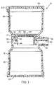
- Figure 1 is an elevation view in section showing a disposable filtration unit of the present invention;
- Figure 2 is a side view of a portion of the unit shown in Figure 1; and
- Figure 3 is a view taken along lines 3-3 of Figure 2.
- Referring to the drawings, Figure 1 shows the filtration unit of the present invention generally indicated at 10. The unit is formed by a generally
cylindrical side wall 12 which has an intermediatenecked portion 14. This necked portion divides the filtration unit into an upper section orreservoir 18 for containing the liquid to be filtered, and alower section receptacle 20 for receiving the filtrate. - A
pouring spout 22 extending from and formed integral with the neck portion communicates withreceptacle 20. It should be appreciated that except for the necked portion and the pouring spout, thecylindrical side wall 12 is continuous and unbroken over its full height. - The
cylindrical side wall 12 has anopen top 24 which can be closed by aremovable cover 23. The bottom of the cylinder, however, is closed by aclosure 26 which can be either formed integral with the cylindrical wall or can be a separate cap member fixed to the cylindrical wall by any suitable means such as a solvent or ultrasonic welding. - Formed integral with
side wall 12 at thenecked portion 14 is a first, internalannular shoulder 28. - As best seen in Figure 2, a
flange 30 depends from about the inner periphery ofshoulder 28. The inside diameter of this flange defines anopening 32. The lower end offlange 30 is provided with a second, internalannular shoulder 34 the inside diameter of which, defines asecond opening 36. These twoopenings lower opening 36 is slightly smaller in diameter than theupper opening 32 for purposes set out hereinbelow. - As shown in Figures 1 and 2,
spout 22 includes abreather tube 38. This tube is formed by apartition 40 which extends across the spout and extends back through the spout intoreceptacle 20 to intersect and merge withflange 30. - It should be appreciated that the unit as thus far described can be molded in one piece from polystyrene, or other suitable plastic materials. Preferably the plastic should be of the type which is heat degraded so that the filtration unit cannot be sterilized and must be discarded after use. Further, any one of several molding techniques such as blow molding or injection molding may be used to form the structure as described hereinabove.
- The second major component of the
filtration unit 10 is afilter medium support 42. This support comprises aperforated disc 44 having an integrally formedannular collar 46 which depends from the disc. It should be appreciated that the diameter ofperforated disc 44 is substantially the same as the internal diameter of thenecked portion 14. The outside diameter ofcollar 46 depending from the disc is slightly less than the diameter of opening 32 so the collar fits easily through this opening as shown in Figure 2. In addition, thecollar 46 is tapered and is of a length sufficient to extend through thelower opening 36 in the second (lower)shoulder 34 and slightly below the level ofspout 22. The outside diameter ofcollar 46 where it extends throughopening 36 is slightly greater than the inside diameter of this opening so as to provide an interference fit with thelower shoulder 34. With this arrangement, thefilter medium support 42 can be fixed within thefiltration unit 10 and againstshoulder 28 simply by inserting the collar throughopenings disc 44 to the internal surface of theneck portion 14 by any suitable means such as ultrasonic welding or an appropriate solvent. - Because
collar 46 has an interference fit with thelower shoulder 34, an annular channel orair passage 48 is defined about the collar. As best seen in Figures 1 and 3 thischannel 48 communicates with thebreather tube 38 at 50 on one side of thecollar 46 and communicates withreceptacle 20 on the other side of the collar through aslot 52 formed in the dependingflange 30. Except for these points of communication,channel 48 is otherwise closed by the tight fit of thecollar 46 to theshoulder 34 on one level and the welding of the periphery ofdisc 44 to theneck portion 14 on an upper level. Thus, with the assembly as shown in Figure 1,breather tube 38 opens intoreceptacle 20 only at 52 which is a point farthest fromspout 22. This insures that when thefiltration unit 10 is tipped to pour the contents ofreceptacle 20 throughspout 22, the air entering the receptacle throughbreather tube 38 does not bubble through or otherwise come into active contact with the liquid in the receptacle. This minimizes any possible chemical reaction between the air and the filtrate or contamination of the filtrate by air borne bacteria carried by the air entering the receptacle. - To complete the filter, the upper surface of
disc 44 is provided with aseat 54 to receive the appropriate sheet-like filter medium 56. Such a filter medium can be any of various suitable materials such as a standard filter membrane having any desired degree of porosity. The attachment of the filter medium todisc 44 can be accomplished by sonic or heat sealing prior to the assembly of the filter support to the side wall of thenecked portion 14 andshoulder 28. - In addition to being a pouring spout, spout 22 can also be attached by a conventional connector (not shown) to a suitable means for evacuating
receptacle 20 so as to facilitate the filtration of liquid through the filter medium. - Thus, it should be appreciated that the present invention provides a filtration unit and a method of its manufacture which is an improvement over the state of the art. In this respect, molding the body of the unit in one piece, not only reduces the cost of manufacture, but also provides a unitary structure which eliminates any problems of air leaking into the receptacle from a point downstream of the filter medium. The present invention further allows for the complete assembly of the filtration unit in only two significant steps; namely, the attachment of a filter medium to support 42 and the attachment of the support to the wall of
necked portion 14 andshoulder 34. - The filter unit of the present unit also provides a unique design for pouring filtrate from the
receptacle 20 without having the air which enters the receptacle actively contact the filtrate. In this respect, thecollar 46,partition 40 andshoulder 34 cooperate to extend the length ofbreather tube 38 so as to locate the entrance of the breather tube atslot 52. This entrance is at a point where it is least likely that any air entering the receptacle will come into active contact with the filtrate in the receptacle as the filtrate is poured throughspout 22. Moreover, by havingcollar 46 extend through thelower shoulder 34 and below the level ofspout 22, there is little or no danger of filtrate aspirating through the spout as a vacuum is being drawn. Thus, the present invention does provide a simple easily manufactured and inexpensive disposable filtration unit.
Claims (7)
characterised in that the breather tube (38) is integral with the cylindrical side wall (12), extends through and is wholly isolated from the pouring spout (22), and communicates with the lower receptacle (20), adjacent the cylindrical side wall (12) and diametrically opposite the spout (22), by means of an air passage (48).
Applications Claiming Priority (2)
| Application Number | Priority Date | Filing Date | Title |
|---|---|---|---|
| US06/238,818US4357240A (en) | 1981-02-27 | 1981-02-27 | Disposable, one-piece filter unit |
| US238818 | 1981-02-27 |
Publications (2)
| Publication Number | Publication Date |
|---|---|
| EP0059284A1 EP0059284A1 (en) | 1982-09-08 |
| EP0059284B1true EP0059284B1 (en) | 1985-05-29 |
Family
ID=22899452
Family Applications (1)
| Application Number | Title | Priority Date | Filing Date |
|---|---|---|---|
| EP81304577AExpiredEP0059284B1 (en) | 1981-02-27 | 1981-10-02 | Disposable, one-piece filter unit and method of manufacturing the same |
Country Status (6)
| Country | Link |
|---|---|
| US (1) | US4357240A (en) |
| EP (1) | EP0059284B1 (en) |
| JP (1) | JPS6044963B2 (en) |
| AU (1) | AU536589B2 (en) |
| CA (1) | CA1170196A (en) |
| DE (1) | DE3170737D1 (en) |
Families Citing this family (42)
| Publication number | Priority date | Publication date | Assignee | Title |
|---|---|---|---|---|
| US4559837A (en)* | 1981-10-01 | 1985-12-24 | Cerqueira Francisco L | Faeces collection and concentration receiver |
| US4786471A (en)* | 1983-10-21 | 1988-11-22 | Baxter Travenol Laboratories, Inc. | Heterogeneous immunoassay method and assembly |
| US4685472A (en)* | 1984-01-23 | 1987-08-11 | Rudolph Muto | Specimen collector |
| DE3427114A1 (en)* | 1984-07-23 | 1986-01-30 | A. Dr.med. 8022 Grünwald Szabados | Sample receptacle for paste-like sample material and method for processing paste-like sample material |
| US4678579A (en)* | 1984-12-05 | 1987-07-07 | Whale Scientific, Inc. | Disposable unitary cytology chamber and filter card for centrifugation of fluid samples and method of making same |
| EP0211155A3 (en)* | 1985-08-09 | 1987-04-29 | Becton, Dickinson and Company | Disposable filter unit |
| US4774058A (en)* | 1985-09-26 | 1988-09-27 | Mehl Ehrenfried L | Apparatus for, and methods of, operating upon a fluid |
| US4689147A (en)* | 1985-09-27 | 1987-08-25 | Nalge Company | Plastic filter assembly |
| USD297860S (en) | 1985-10-18 | 1988-09-27 | Nalge Company | Filter unit |
| US4673501A (en)* | 1985-11-19 | 1987-06-16 | Miles Laboratories, Inc. | Bottle top filter |
| US4702834A (en)* | 1986-06-17 | 1987-10-27 | Nalge Company | Plastic filter units having a weld cellulose filter |
| US4921618A (en)* | 1987-07-01 | 1990-05-01 | Basf Corporation | Inverted separation and transfer device, and process for using same |
| US4783318A (en)* | 1987-10-02 | 1988-11-08 | The State Of Minnesota | Apparatus for environmental leaching testing |
| GB8729208D0 (en)* | 1987-12-15 | 1988-01-27 | Sev Trent Water Authority | Filtering & filters for liquids |
| FR2637198B1 (en)* | 1988-09-14 | 1990-12-28 | Carre Gerard | FUNNEL BODY MADE OF NATURAL POLYPROPYLENE |
| US5364597A (en)* | 1991-03-13 | 1994-11-15 | Cytyc Corporation | Apparatus for collection and transfer of particles |
| USD343682S (en) | 1991-12-02 | 1994-01-25 | Corning Incorporated | Vacuum filter flask |
| US5277209A (en)* | 1992-06-08 | 1994-01-11 | Olson Gene R | Pumpless parts washing apparatus |
| US5308483A (en)* | 1992-08-27 | 1994-05-03 | Gelman Sciences Inc. | Microporous filtration funnel assembly |
| US5440942A (en)* | 1994-02-02 | 1995-08-15 | Hubbard; Stephen H. | Biological sample collecting and holding device |
| GB9422504D0 (en)* | 1994-11-08 | 1995-01-04 | Robertson Patricia M B | Blood testing |
| US5603900A (en)* | 1995-05-19 | 1997-02-18 | Millipore Investment Holdings Limited | Vacuum filter device |
| US5762071A (en)* | 1995-12-26 | 1998-06-09 | Newman; Dennis | Kidney stone specimen collection system |
| US5725763A (en)* | 1996-06-24 | 1998-03-10 | Millipore Corporation | Vacuum filtration device sealable vacuum vent |
| EP1012327B1 (en) | 1997-01-29 | 2006-01-11 | Pall Corporation | Filtration assembly |
| GB9710773D0 (en)* | 1997-05-23 | 1997-07-23 | Life Sciences Int Europe | Cytofunnel arrangement |
| US6458278B1 (en)* | 1999-02-22 | 2002-10-01 | Nalge Nunc International Corporation | Filtering unit having separately attachable filter cassette, filter cassette, and method of filtering |
| US20020096468A1 (en)* | 2000-12-04 | 2002-07-25 | Peter Zuk | Disposable vacuum filtration apparatus capable of detecting microorganisms and particulates in liquid samples |
| US7661538B1 (en) | 2001-05-31 | 2010-02-16 | Roush Life Science, LLC | Disposable vacuum filtration funnel with integral prefilter |
| US7011755B2 (en)* | 2001-05-31 | 2006-03-14 | Zuk Jr Peter | Disposable vacuum filtration funnel with integral prefilter |
| US20050232824A1 (en)* | 2004-04-14 | 2005-10-20 | Pangrcic Robert A | High temperature electrolyte testing container |
| US7507578B2 (en)* | 2004-10-21 | 2009-03-24 | Cytyc Corporation | Reduced aperture biological specimen collection and transfer device |
| JP2009506886A (en)* | 2005-09-02 | 2009-02-19 | ピーター ジュニア ズク, | System, apparatus and method for vacuum filtration |
| US8158009B2 (en)* | 2007-05-23 | 2012-04-17 | Roush Life Sciences, Llc | Methods and apparatus for foam control in a vacuum filtration system |
| US8157104B2 (en)* | 2007-07-26 | 2012-04-17 | Roush Life Sciences, Llc | Apparatus for supporting a vacuum filtration device |
| US8231012B2 (en)* | 2007-07-26 | 2012-07-31 | Roush Life Sciences, Llc | Filtrate storage system |
| US8808552B2 (en)* | 2010-12-16 | 2014-08-19 | Zenpure (Hangzhou) Co., Ltd. | Stackable filter cup apparatus and method |
| CN102621300B (en)* | 2011-01-26 | 2015-05-27 | 上海铭源数康生物芯片有限公司 | Device and method for removing cellulose nitrate film based protein chip luminescent substrate |
| CN103239917B (en) | 2013-03-25 | 2015-11-18 | 绍兴鹭铧色谱分离设备有限公司 | Disposable integrated macromolecule vacuum filtration funnel |
| JP6502354B2 (en)* | 2013-09-05 | 2019-04-17 | メルク パテント ゲゼルシャフト ミット ベシュレンクテル ハフツングMerck Patent Gesellschaft mit beschraenkter Haftung | Filter device for filtering complex fluid samples |
| US10278534B2 (en)* | 2013-12-01 | 2019-05-07 | Fellow Industries Inc. | Beverage steeping and dispensing system |
| KR102071046B1 (en)* | 2018-02-05 | 2020-01-28 | 주식회사 이노디자인 | Dripper and portable coffee drinking tumbler |
Family Cites Families (4)
| Publication number | Priority date | Publication date | Assignee | Title |
|---|---|---|---|---|
| US2541524A (en)* | 1945-06-16 | 1951-02-13 | Leon Pedro | Demijohn filter |
| BE538818A (en)* | 1954-07-19 | 1900-01-01 | ||
| US3295686A (en)* | 1965-05-20 | 1967-01-03 | Rockridge Lab | Filter unit |
| US4180383A (en)* | 1975-04-07 | 1979-12-25 | Becton, Dickinson And Company | Chamber holder for immobilized immunoadsorbent |
- 1981
- 1981-02-27USUS06/238,818patent/US4357240A/ennot_activeExpired - Fee Related
- 1981-10-02EPEP81304577Apatent/EP0059284B1/ennot_activeExpired
- 1981-10-02DEDE8181304577Tpatent/DE3170737D1/ennot_activeExpired
- 1981-10-08AUAU76137/81Apatent/AU536589B2/ennot_activeCeased
- 1981-10-27CACA000388862Apatent/CA1170196A/ennot_activeExpired
- 1981-11-30JPJP56190948Apatent/JPS6044963B2/ennot_activeExpired
Also Published As
| Publication number | Publication date |
|---|---|
| JPS6044963B2 (en) | 1985-10-07 |
| DE3170737D1 (en) | 1985-07-04 |
| AU7613781A (en) | 1982-09-02 |
| CA1170196A (en) | 1984-07-03 |
| JPS57144014A (en) | 1982-09-06 |
| AU536589B2 (en) | 1984-05-10 |
| EP0059284A1 (en) | 1982-09-08 |
| US4357240A (en) | 1982-11-02 |
Similar Documents
| Publication | Publication Date | Title |
|---|---|---|
| EP0059284B1 (en) | Disposable, one-piece filter unit and method of manufacturing the same | |
| CA1138384A (en) | Non-collapsible medical fluid container with air vent filter | |
| US5792425A (en) | Vacuum filter device | |
| US4487606A (en) | Suction canister with shut-off valve and smoke filter | |
| US4465485A (en) | Suction canister with unitary shut-off valve and filter features | |
| US9409165B2 (en) | Filter vial | |
| US4301010A (en) | Vacuum filter | |
| CA1321953C (en) | Sample filtration device | |
| US5308483A (en) | Microporous filtration funnel assembly | |
| EP1841662B1 (en) | Leak resistant drinking cup | |
| US4516973A (en) | One-piece disposable collection bag having a rigid cover for a suction canister unit | |
| CA1293712C (en) | Filter for centrifuge tube | |
| RU2070531C1 (en) | Device for dispensing sterile solution from container | |
| US6171261B1 (en) | Specimen collection device and method of delivering fluid specimens to test tubes | |
| KR920009661B1 (en) | Air cleaner | |
| EP0363172A2 (en) | Liquid dispenser nozzle assembly | |
| GB2040890A (en) | Dispensing closure for a container | |
| WO1995004585A1 (en) | Vacuum filtration device | |
| EP0321064A1 (en) | Bottle filter | |
| US4317525A (en) | Disposable body fluid collection device | |
| JPS59206027A (en) | Small filter for gas filtering | |
| JPH02297372A (en) | medical liquid bottle infusion device | |
| JPH0426363Y2 (en) | ||
| JPH055930Y2 (en) | ||
| JPH0441921Y2 (en) |
Legal Events
| Date | Code | Title | Description |
|---|---|---|---|
| PUAI | Public reference made under article 153(3) epc to a published international application that has entered the european phase | Free format text:ORIGINAL CODE: 0009012 | |
| AK | Designated contracting states | Designated state(s):BE CH DE FR GB IT LU NL SE | |
| 17P | Request for examination filed | Effective date:19821004 | |
| ITF | It: translation for a ep patent filed | ||
| GRAA | (expected) grant | Free format text:ORIGINAL CODE: 0009210 | |
| AK | Designated contracting states | Designated state(s):BE CH DE FR GB IT LI LU NL SE | |
| REF | Corresponds to: | Ref document number:3170737 Country of ref document:DE Date of ref document:19850704 | |
| ET | Fr: translation filed | ||
| PG25 | Lapsed in a contracting state [announced via postgrant information from national office to epo] | Ref country code:LU Free format text:LAPSE BECAUSE OF NON-PAYMENT OF DUE FEES Effective date:19851031 | |
| BECA | Be: change of holder's address | Free format text:850529 *SYBRON CORP.PARK 80 WEST PLAZA I, SADDLE BROOK NEW JERSEY 07662-5808 | |
| PLBE | No opposition filed within time limit | Free format text:ORIGINAL CODE: 0009261 | |
| STAA | Information on the status of an ep patent application or granted ep patent | Free format text:STATUS: NO OPPOSITION FILED WITHIN TIME LIMIT | |
| 26N | No opposition filed | ||
| REG | Reference to a national code | Ref country code:GB Ref legal event code:732 | |
| ITPR | It: changes in ownership of a european patent | Owner name:CESSIONE;NALGE COMPANY | |
| PGFP | Annual fee paid to national office [announced via postgrant information from national office to epo] | Ref country code:SE Payment date:19891010 Year of fee payment:9 | |
| PGFP | Annual fee paid to national office [announced via postgrant information from national office to epo] | Ref country code:BE Payment date:19891020 Year of fee payment:9 | |
| PGFP | Annual fee paid to national office [announced via postgrant information from national office to epo] | Ref country code:CH Payment date:19891024 Year of fee payment:9 | |
| PGFP | Annual fee paid to national office [announced via postgrant information from national office to epo] | Ref country code:LU Payment date:19891027 Year of fee payment:9 | |
| PGFP | Annual fee paid to national office [announced via postgrant information from national office to epo] | Ref country code:NL Payment date:19891031 Year of fee payment:9 | |
| REG | Reference to a national code | Ref country code:FR Ref legal event code:TP | |
| REG | Reference to a national code | Ref country code:CH Ref legal event code:PUE Owner name:SYBRON TRANSITION CORP. TRANSFER- NALGE COMPANY | |
| PGFP | Annual fee paid to national office [announced via postgrant information from national office to epo] | Ref country code:GB Payment date:19900921 Year of fee payment:10 | |
| PG25 | Lapsed in a contracting state [announced via postgrant information from national office to epo] | Ref country code:SE Effective date:19901003 | |
| PGFP | Annual fee paid to national office [announced via postgrant information from national office to epo] | Ref country code:FR Payment date:19901012 Year of fee payment:10 | |
| ITTA | It: last paid annual fee | ||
| PG25 | Lapsed in a contracting state [announced via postgrant information from national office to epo] | Ref country code:LI Effective date:19901031 Ref country code:CH Effective date:19901031 Ref country code:BE Effective date:19901031 | |
| NLS | Nl: assignments of ep-patents | Owner name:NALGE COMPANY TE ROCHESTER, NEW YORK, VER. ST. V. | |
| PGFP | Annual fee paid to national office [announced via postgrant information from national office to epo] | Ref country code:DE Payment date:19901130 Year of fee payment:10 | |
| BERE | Be: lapsed | Owner name:SYBRON CORP. Effective date:19901031 | |
| PG25 | Lapsed in a contracting state [announced via postgrant information from national office to epo] | Ref country code:NL Effective date:19910501 | |
| NLV4 | Nl: lapsed or anulled due to non-payment of the annual fee | ||
| REG | Reference to a national code | Ref country code:CH Ref legal event code:PL | |
| PG25 | Lapsed in a contracting state [announced via postgrant information from national office to epo] | Ref country code:GB Effective date:19911002 | |
| GBPC | Gb: european patent ceased through non-payment of renewal fee | ||
| PG25 | Lapsed in a contracting state [announced via postgrant information from national office to epo] | Ref country code:FR Effective date:19920630 | |
| PG25 | Lapsed in a contracting state [announced via postgrant information from national office to epo] | Ref country code:DE Effective date:19920701 | |
| REG | Reference to a national code | Ref country code:FR Ref legal event code:ST | |
| EUG | Se: european patent has lapsed | Ref document number:81304577.0 Effective date:19910603 |