EP0058103A1 - Tridimensional visualization method and device starting from video signals, especially for electronic microscopy - Google Patents
Tridimensional visualization method and device starting from video signals, especially for electronic microscopyDownload PDFInfo
- Publication number
- EP0058103A1 EP0058103A1EP82400075AEP82400075AEP0058103A1EP 0058103 A1EP0058103 A1EP 0058103A1EP 82400075 AEP82400075 AEP 82400075AEP 82400075 AEP82400075 AEP 82400075AEP 0058103 A1EP0058103 A1EP 0058103A1
- Authority
- EP
- European Patent Office
- Prior art keywords
- image
- images
- composite image
- video signals
- line
- Prior art date
- Legal status (The legal status is an assumption and is not a legal conclusion. Google has not performed a legal analysis and makes no representation as to the accuracy of the status listed.)
- Granted
Links
- 238000000386microscopyMethods0.000title1
- 238000007794visualization techniqueMethods0.000title1
- 239000002131composite materialSubstances0.000claimsabstractdescription44
- 238000000034methodMethods0.000claimsabstractdescription25
- 230000003287optical effectEffects0.000claimsdescription11
- 238000012800visualizationMethods0.000abstractdescription9
- 238000003860storageMethods0.000description4
- 238000010894electron beam technologyMethods0.000description2
- 238000012545processingMethods0.000description2
- 238000012935AveragingMethods0.000description1
- 240000008042Zea maysSpecies0.000description1
- 230000005540biological transmissionEffects0.000description1
- 230000015572biosynthetic processEffects0.000description1
- 230000000295complement effectEffects0.000description1
- 238000005520cutting processMethods0.000description1
- 238000011161developmentMethods0.000description1
- 238000001493electron microscopyMethods0.000description1
- 230000008030eliminationEffects0.000description1
- 238000003379elimination reactionMethods0.000description1
- 238000004049embossingMethods0.000description1
- 238000002474experimental methodMethods0.000description1
- 239000000203mixtureSubstances0.000description1
- 230000002093peripheral effectEffects0.000description1
- 230000005855radiationEffects0.000description1
- 230000006798recombinationEffects0.000description1
- 238000005215recombinationMethods0.000description1
- 239000000126substanceSubstances0.000description1
- 230000001360synchronised effectEffects0.000description1
- 238000003786synthesis reactionMethods0.000description1
- 230000000007visual effectEffects0.000description1
Images

Classifications
- H—ELECTRICITY
- H04—ELECTRIC COMMUNICATION TECHNIQUE
- H04N—PICTORIAL COMMUNICATION, e.g. TELEVISION
- H04N5/00—Details of television systems
- H04N5/222—Studio circuitry; Studio devices; Studio equipment
- H04N5/262—Studio circuits, e.g. for mixing, switching-over, change of character of image, other special effects ; Cameras specially adapted for the electronic generation of special effects
- H04N5/2628—Alteration of picture size, shape, position or orientation, e.g. zooming, rotation, rolling, perspective, translation
- H—ELECTRICITY
- H04—ELECTRIC COMMUNICATION TECHNIQUE
- H04N—PICTORIAL COMMUNICATION, e.g. TELEVISION
- H04N13/00—Stereoscopic video systems; Multi-view video systems; Details thereof
- H04N13/30—Image reproducers
- H04N13/302—Image reproducers for viewing without the aid of special glasses, i.e. using autostereoscopic displays
- H04N13/305—Image reproducers for viewing without the aid of special glasses, i.e. using autostereoscopic displays using lenticular lenses, e.g. arrangements of cylindrical lenses
- H—ELECTRICITY
- H04—ELECTRIC COMMUNICATION TECHNIQUE
- H04N—PICTORIAL COMMUNICATION, e.g. TELEVISION
- H04N13/00—Stereoscopic video systems; Multi-view video systems; Details thereof
- H04N13/30—Image reproducers
- H04N13/302—Image reproducers for viewing without the aid of special glasses, i.e. using autostereoscopic displays
- H04N13/31—Image reproducers for viewing without the aid of special glasses, i.e. using autostereoscopic displays using parallax barriers
Definitions
- the inventionrelates to three-dimensional visualization, more commonly known as relief photography.
- Relief photography devices using lenticular networks or "embossings”have already been proposed, in particular, and for a long time, by Mr. Maurice BONNET.
- This techniqueis very advanced, and gives striking results.
- the shootingcan be done either from special devices, incorporating from the shooting a lenticular network (direct process), or by composition of a series of classic flat images of the same object, taken from angles of shooting Le - gèrement different (indirect method).
- This second processvery interesting for scientific observation, takes time because it almost necessarily involves a special photographic processing step, which is both long, delicate, and of negligible cost.
- the present inventionprovides a means which allows very rapid development of relief images.
- the video signalsare advantageously recorded in digital form. It is currently considered that scanning with at least 16 (2 4 ), preferably 32 (2 5 ) to 128 (2 7 ) gray levels is sufficient for most applications.
- the n images (V k ) of the objectare taken at angles (A k ) defined with respect to a common axis
- the regions of the composite imageare adjacent bands parallel to this common axis, while in each of these regions, the por image tions are slices of adjacent images, also parallel to the common axis
- the lenticular networkis a network of lenses in sectors of cylinders whose generatrices are also parallel to the axis common.
- each image slicecorresponds to an area taken in the format of the region in one of the basic images, while the composite image is constructed with an anamorphosis of ratio n between the general direction of the image slices and the direction which is perpendicular thereto. Another anamorphosis is most often required, to account for the tilt of the base images.
- the video signalsare then defined for a line scanning parallel to the common axis, or general direction of the bands and image slices, and each image slice comprises one or more lines of one of the base images.
- the visualizationcan be carried out on a cathoscope, then photographed; the composite image thus obtained directly only has to receive a lenticular network.
- a digital output membercapable of image reproduction on a recording medium.
- the basic imagescan be generated directly in the form of video signals (electronic image generation), one can also take n basic images (V k ) of the object using a video camera, from different angles (A k ), and selectively record these n basic images.
- the inventionapplies in particular to the case of electron microscopes, where the n basic images are taken by placing the object at n different angles.
- the number n of the basic imagesis at least equal to 4, preferably at least equal to 8; the number of regions (or bands) of the composite image - each comprising n respective portions or slices of the basic images - is of the order of magnitude of several hundred and depends in particular on the size of the relief image that l 'we wish to obtain finally.
- the inventionalso relates to the devices for implementing the above method.
- the references 11, lk and lnshow diagrammatically the image generator of the same electron microscope, observing an object 0, the electronic image of which is displayed on a fluorescent screen E.
- the deviceis seen in plane section, and illustrates the fact that n electronic images of the object are taken successively at respective angles A k , with k varying from 1 to n.
- the angles of vieware considered with respect to a common axis passing through the intersection of the object (or its main plane) with the "optical" axis X of the electron microscope, this common axis also being perpendicular to the plan of the figure.
- the angle of view (A k )is the angle between the plane normal to the figure which passes through the optical axis X and a plane normal to the main plane of the object.
- angles (A k )are distributed regularly around the optical axis X.
- the video signals produced by the camera 20, and which correspond to the video image V 1are transmitted to a video image storage device 30. It will be the same for all the other views of the object from the different angles, and in particular for the view v k with the associated video image V k , and for the view v n , with the associated video image V n .
- the fact that the camera successively supplies the image storage device 30 with the video signals corresponding to each of the images takenis illustrated in FIG. 1 by dashed lines, the camera 20 being illustrated in position for each of the angles of shots represented.
- the image storage device 30After the n shots thus taken, the image storage device 30 therefore comprises n sets of video information, corresponding respectively to n basic images (V k ) of the object, taken with the same field, but under the different angles (A k ). This constitutes operation a) of the method according to the invention. Note, however, that instead of generating these video signals by effective shooting, they can be produced in another way, in particular using the devices known as electronic image generators.
- FIG. 1also includes a device 40, which is used to control the synthesis of the composed image, in cooperation with an image portion selector 31, an anamorphosis device 32, and a display device proper of the composite image, denoted 50.
- this device 50is illustrated simply in the form of the screen which will give the composite image, in order to allow a better understanding of the present invention.
- the device 40will act on the image memory 30 and on the image portion selector 31, so that the latter first selects a portion P 11 of the electronic image V 1 then a corresponding portion, denoted P 12 and taken in the image V 22 and so on, a portion P lk , taken in the image V k , to finally go to the last portion P ln , taken in the basic image V n .
- the set of these image portions P 1taken successively from the different base images, constitutes the first region R 1 of the composite image.
- the regions such as R 1 of the composite imageare dice bands, here horizontal, while the portions, such as P 1 , which constitute these regions, such as R 1 , are slices taken respectively from each of the basic images. These sections then extend parallel to each other, and adjacent to each other, and thereby define regions of parallel general direction.
- One of the simplest waysis to take purely and simply in each of the basic images a portion whose format corresponds to the geometry of the region. But, in this case, since each region consists of n adjacent slices, one of the dimensions of each region will be n times too large compared to the other.
- the device 32then comes to carry out an anamorphosis of the portions or slices of image selected by the device 31, in order to restore a correct geometry of the image.
- anamorphosisaccording to which one extends by a ratio n each of the image portions or slices.
- the anamorphosiscan be carried out on the contrary by condensing each portion or slice of image selected in one of the basic images according to its width, and by making for example the average of n light points taken transversely in each of the slices .
- many other intermediate solutionsare possible between these two extreme solutions, according to which one could for example lengthen by a ratio less than n the slices taken from the basic images, and shrink them in width of the complementary ratio, in order to restore the normal format desired for the composite image.
- region R 1 of the composite imagehas been described in detail.
- the following region R 2is produced in the same way, first taking a slice P 21 of the video image V 1 , then a slice P 22 of the video image V 2 , and so on a slice P 2k from image V kl up to section P 2n of the last base image V. This process then continues, for all the regions desired.
- the composite imageAfter the composite image has been entirely constituted, it is either photographed, if the display device 50 is a video screen, or used as it is, if this device is of a type directly providing an image on recording medium, and an appropriate lenticular network is superimposed on the composite image.
- the lenticular networkwill be a network of lenses in the sector of a cylinder, the generatrices of which are parallel to the main direction of the image slices. It can therefore be seen that the configuration of the lenticular network used corresponds to the configuration of the regions or bands as well as to that of the portions or slices appearing in the composite image.
- the optical characteristics of each of the elementary lenses of the arrayare adapted to the arrangement of the image slices in each of the regions, in particular with a field angle and a suitable focal length.
- a lenticular networkin the sector of a cylinder, one could also use a lenticular network formed of a multitude of spheres, or spherular network. In such a network, the shape of the regions would reproduce the mesh of the lenticular network. The shooting is a little more complicated, the angles of shots can be more numerous and established in several directions. The same is true for the selection of the image portions.
- each of the points of each of the imagesby first defining an image address, for example from 1 to n, a line address, for example from 1 to 625, and an address point on the line, for example from 1 to 400. It will be considered for the remainder of the description that a display clock 40 is capable of defining these address signals at a coordinated rate, in such a way that define in each image, then in each line, the line point addresses at a frequency F.
- the digital image memorycomprises for example sixteen bits, which is currently estimated as minimum for good reproduction , and corresponds to sixteen levels of gray.
- the digital image memory 35will exit the image points at the frequency F, starting with the first line of the first image, then the first line of the second image, etc. , to the first line of image n; we then continue with the second line of each of the images, and so on until the 625th line.
- the video signals thus delivered by the memory 35are applied to a digitally controlled image display member 50.
- This member 50is chosen with an image definition clearly greater than that of the video camera 20, so that it can provide n times 625 lines, and on each line n times 400 points, in the example previously chosen.
- the display clockWhen it addresses digital memory 35, the display clock first fixes the line address, in order to address each of the images successively. On the contrary, when it addresses the display unit of i mage 50, clock 40 provides a combined line + image address, which is incremented each time the image address or line address increases by one. Consequently, the image display member 50 will be on the first line when it is a question in the digital memory 35 of addressing the first line of the first image; the member 50 will be placed on its second line when the first line of the second image is addressed in the memory 35, and so on until the first line of the image n. We then continue with the second line of each of the images, to go until all the lines of all the images are exhausted. It can therefore be seen that in this way it will be possible to fill in the image display member 500n times 625 lines.
- the display clock 40supplies addresses of image points in the direction of the image display member 50, but this time at a frequency n times F. In this way, the display member 50 will deliver n consecutive points for the same information at the output of the digital image memory 35. This very simply achieves the anamorphosis by elongation of the image slices, here lines, which we have described above with respect to the device 32 of FIG. 1.
- the objectis seen at angles that are differently inclined on the optical axis. Anamorphosis should also take this into account, preferably. If we admit that the object covers 625 lines when it is perpendicular to the optical axis, it will cover for example 624 when it is slightly inclined, the 625th line being useless. We can then replace the unnecessary 625th line with a repetition of the 624th line.
- the change in format of the inclined imageis proportional to 1 - cos alpha. Whenever the variation of 1 - cos alpha cor responds to a line of the scan, a line will be repeated in the image V k concerned to make up for the difference in format of the field observed.
- a composite imageis obtained on the image display member which already contains all the information necessary for a visualization in relief, with a lenticular network in appropriate cylinder sector.
- the image display member 50may be a cathode ray tube or cathoscope with digital control.
- a cathode ray tubewith or without memory. It is then necessary to photograph the image thus obtained, and subject it to the usual processing operations, but in a single copy, and without problem of recombination to arrive at the composite image, the latter being developed from the start.
- a digitally controlled image reproduction memberwhich by itself delivers a permanent image, for example the peripheral sold under the name VISOR by Soro electrooptique or similar devices of Bell & Howell. Such devices are commonly used in connection with computers in order to obtain photographs with variable density. As before, it will then suffice to apply appropriate characteristics to the image thus obtained with lenticular grating with cylinder sectors.
- each slice used in the composite imageis defined by a single line taken as is from one of the basic images, with an anamorphosis of ratio n over its length.
- each slice of the composite imageis of course possible to constitute each slice of the composite image from several adjacent lines of the base image, if the ultimately desired definition allows it.
- one of the preferred applications of the inventionrelates to the electron microscope.
- scanning electron microscopesthe main electron beam is subjected to a television type scan, and a detector collects the radiation (electrons or x-rays in general) emanating from the various points successively explored in the object.
- the signal from the detectoris applied directly as a luminance control to a cathode-ray display tube whose scanning is synchronous with that of the electron beam on the object.
- the screen of the cathode ray tubewould then play the role of the screen E already mentioned, but the device is very advantageously simplified by directly storing - with digitization - the signals coming from the detector.
- the present inventionallows an almost complete elimination of photographic operations, and thereby a considerable saving of time, the saving of costs due to photographic products (sensitive surface and chemicals), and also the possibility of practically working. in real time.
Landscapes
- Engineering & Computer Science (AREA)
- Multimedia (AREA)
- Signal Processing (AREA)
- Image Processing (AREA)
- Length Measuring Devices By Optical Means (AREA)
- Closed-Circuit Television Systems (AREA)
- Testing, Inspecting, Measuring Of Stereoscopic Televisions And Televisions (AREA)
- Investigating Or Analysing Biological Materials (AREA)
Abstract
Description
Translated fromFrenchL'invention concerne la visualisation tri-dimensionnelle, plus communément connue sous le nom de photographie en relief.The invention relates to three-dimensional visualization, more commonly known as relief photography.
Des dispositifs de photographie en relief utilisant des réseaux lenticulaires ou "gaufrages" ont déjà été proposés, en particulier, et depuis longtemps, par Monsieur Maurice BONNET. Cette technique est très au point, et donne des résultats saisissants. La prise de vue peut se faire soit à partir d'appareils spéciaux, incorporant dès la prise de vue un réseau lenticulaire (procédé direct), soit par composition d'une série d'images planes classiques du même objet, réalisées sous des angles de prise de vue lé- gèrement différents (procédé indirect). Ce second procédé, très intéressant pour l'observation scientifique, prend du temps car il fait quasi nécessairement intervenir une étape spéciale de traitement photographique, qui est à la fois longue, délicate, et d'un coût négligeable.Relief photography devices using lenticular networks or "embossings" have already been proposed, in particular, and for a long time, by Mr. Maurice BONNET. This technique is very advanced, and gives striking results. The shooting can be done either from special devices, incorporating from the shooting a lenticular network (direct process), or by composition of a series of classic flat images of the same object, taken from angles of shooting Le- gèrement different (indirect method). This second process, very interesting for scientific observation, takes time because it almost necessarily involves a special photographic processing step, which is both long, delicate, and of negligible cost.
Dans un certain nombre d'applications, il serait au contraire nécessaire de disposer rapidement - quasi en temps réel - d'une image composite. C'est le cas notamment en microscopie électronique.On the contrary, in a certain number of applications, it would be necessary to have a composite image quickly - almost in real time. This is particularly the case in electron microscopy.
La présente invention vient apporter un moyen qui permet l'élaboration très rapide d'images en relief.The present invention provides a means which allows very rapid development of relief images.
A cet effet, l'invention propose un procédé qui comprend les opérations suivantes :
- a) engendrer n jeux de vidéo-signaux (Sk; k variant de 1 à n), correspondant respectivement à n images de base (Vk) de l'objet, prises avec le même champ, mais sous différents angles (Ak) ;
- b) construire une image composite constituée de régions contiguës, dont chacune se compose de n portions définies respectivement à partir des n jeux de vidéo-signaux, en choisissant dans chaque jeu les vidéo-signaux relatifs à la région concernée de l'image composite, ces n portions étant de surcroît agencées d'une manière qui correspond aux angles de prise de vue (Ak).
- a) generate n sets of video signals (Sk ; k varying from 1 to n), corresponding respectively to n basic images (Vk ) of the object, taken with the same field, but from different angles (Ak );
- b) construct a composite image made up of contiguous regions, each of which consists of n portions defined respectively from the n sets of video signals, by choosing in each set the video signals relating to the region concerned of the composite image, these n portions being moreover arranged in a manner which corresponds to the angles of view (Ak ).
Au terme de cette opération b), on dispose déjà de l'image composite contenant les informations nécessaires pour la visualisation du relief. Le procédé se complète, immédiatement ou ultérieurement, par une autre opération :
- c) disposer en coopération optique avec l'image composite ainsi construite un réseau lenticulaire, dans lequel la configuration du réseau correspond à la configuration des régions dans l'image composite, tandis que les caractéristiques optiques de chaque lentille élémentaire du réseau sont adaptées à l'arrangement des portions composant la région de l'image composite qui est associée à la lentille élémentaire concernée.
- c) having in optical cooperation with the composite image thus constructed a lenticular array, in which the configuration of the array corresponds to the configuration of the regions in the composite image, while the optical characteristics of each elementary lens of the array are adapted to the arrangement of the portions composing the region of the composite image which is associated with the elementary lens concerned.
A l'opération a), les vidéo-signaux sont avantageusement enregistrés sous forme numérique. On considère actuellement qu'une numérisation avec au moins 16 (24), de préférence 32 (25) à 128 (27) niveaux de gris est suffisante pour la plupart des applications.In operation a), the video signals are advantageously recorded in digital form. It is currently considered that scanning with at least 16 (24 ), preferably 32 (25 ) to 128 (27 ) gray levels is sufficient for most applications.
Dans un mode de réalisation préférentiel de l'invention, à l'opération a), les n images (Vk) de l'objet sont prises suivant des angles (Ak) définis par rapport à un axe commun, à l'opération b), les régions de l'image composite sont des bandes adjacentes parallèles à cet axe commun, tandis que dans chacune de ces régions, les portions d'image sont des tranches d'images adjacentes, également parallèles à l'axe commun, et à l'opération c), le réseau lenticulaire est un réseau de lentilles en secteurs de cylindres dont les génératrices sont également parallèles à l'axe commun.In a preferred embodiment of the invention, in operation a), the n images (Vk ) of the object are taken at angles (Ak ) defined with respect to a common axis, in operation b), the regions of the composite image are adjacent bands parallel to this common axis, while in each of these regions, the por image tions are slices of adjacent images, also parallel to the common axis, and in operation c), the lenticular network is a network of lenses in sectors of cylinders whose generatrices are also parallel to the axis common.
Ceci peut être réalisé pratiquement de la manière suivante : chaque tranche d'image correspond à une zone prise au format de la région dans l'une des images de base, tandis que l'image composite est construite avec une anamorphose de rapport n entre la direction générale des tranches d'image et la direction qui lui est perpendiculaire. Une autre anamorphose est le plus souvent nécessaire, pour tenir compte de l'inclinaison des images de base.This can be done practically in the following way: each image slice corresponds to an area taken in the format of the region in one of the basic images, while the composite image is constructed with an anamorphosis of ratio n between the general direction of the image slices and the direction which is perpendicular thereto. Another anamorphosis is most often required, to account for the tilt of the base images.
Quoique l'on sache découper une.image vidéo de toute manière désirée, il est plus simple de faire un découpage parallèle aux lignes : les signaux vidéo sont alors définis pour un balayage ligne parallèle à l'axe commun, ou direction générale des bandes et tranches d'image, et chaque tranche d'image comprend une ou plusieurs lignes de l'une des images de base.Although we know how to cut a video image in any desired way, it is simpler to make a cutting parallel to the lines: the video signals are then defined for a line scanning parallel to the common axis, or general direction of the bands and image slices, and each image slice comprises one or more lines of one of the base images.
Dans un mode de réalisation particulier de l'invention, l'opération b) consiste à :
- b1) définir un numéro de ligne L initialement égal à 1,
- b2) chercher en mémoire la ligne de rang L de l'image de base d'angle A1,
- b3) exciter une ligne d'un afficheur d'image selon chaque point de la ligne L de l'image de base d'angle A1, répété n fois consécutivement,
- b4) répéter sélectivement les opérations b2) et b3) pour la ligne de rang L des autres images de base, dans l'ordre des angles, et
- b5) répéter les opérations b2) à b4) après avoir à chaque fois incrémenté le numéro de ligne L, et ce jusqu'à épuisement des lignes.
- b1) define a line number L initially equal to 1,
- b2) search in memory for the row of row L of the basic image of angle A1 ,
- b3) excite a line of an image display according to each point of the line L of the basic image of angle A1 , repeated n times consecutively,
- b4) selectively repeat operations b2) and b3) for the row of row L of the other basic images, in the order of the angles, and
- b5) repeat operations b2) to b4) after having incremented each time the line number L, and this until all lines are exhausted.
Dans l'opération b), la visualisation peut s'effectuer sur un cathoscope, ensuite photographié; l'image composite ainsi obtenue directement n'a plus qu'à recevoir un réseau lenticulaire. Mieux, on peut utiliser, en particulier dans le cas de vidéo-signaux numériques, un organe de sortie numérique capable de reproduction d'image sur un support d'enregistrement.In operation b), the visualization can be carried out on a cathoscope, then photographed; the composite image thus obtained directly only has to receive a lenticular network. Better still, one can use, in particular in the case of digital video signals, a digital output member capable of image reproduction on a recording medium.
Bien que les images de base puissent être engendrées directement sous forme de vidéo-signaux (génération électronique d'images), on peut aussi prendre n images de base (Vk) de l'objet à l'aide d'une caméra vidéo, sous les angles différents (Ak), et enregistrer sélectivement ces n images de base.Although the basic images can be generated directly in the form of video signals (electronic image generation), one can also take n basic images (Vk ) of the object using a video camera, from different angles (Ak ), and selectively record these n basic images.
L'invention s'applique en particulier au cas des microscopes électroniques, où les n images de base sont prises en disposant l'objet sous n angles différents.The invention applies in particular to the case of electron microscopes, where the n basic images are taken by placing the object at n different angles.
En pratique, le nombre n des images de base est au moins égal à 4, de préférence au moins égal à 8; le nombre des régions (ou bandes) de l'image composite - comprenant chacune n portions ou tranches respectives des images de base - est de l'ordre de grandeur de plusieurs centaines et dépend notamment de la taille de l'image en relief que l'on désire obtenir finalement.In practice, the number n of the basic images is at least equal to 4, preferably at least equal to 8; the number of regions (or bands) of the composite image - each comprising n respective portions or slices of the basic images - is of the order of magnitude of several hundred and depends in particular on the size of the relief image that l 'we wish to obtain finally.
L'invention concerne aussi les dispositifs pour la mise en oeuvre du procédé ci-dessus.The invention also relates to the devices for implementing the above method.
D'autres caractéristiques et avantages de l'invention apparaîtront à la lecture de la description détaillée qui va suivre, faite en référence aux dessins annexés, sur lesquels :
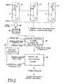
- La figure 1 illustre schématiquement de manière générale la mise en oeuvre du procédé selon l'invention; et
- la figure 2 illustre schématiquement une mise en oeuvre particulière de ce procédé.
- Figure 1 schematically illustrates in general the implementation of the method according to the invention; and
- FIG. 2 schematically illustrates a particular implementation of this method.
La description détaillée se place tout d'abord dans le cadre de l'application au microscope électronique à transmission.The detailed description is placed first as part of the application to the transmission electron microscope.
Sur les figures 1 et 2, les références 11, lk et ln schématisent le générateur d'image d'un même microscope électronique, observant un objet 0, dont l'image électronique est visualisée sur un écran fluorescent E. Le dispositif est vu en coupe plane, et illustre le fait que n images électroniques de l'objet sont prises successivement suivant des angles respectifs Ak, avec k variant de 1 à n. Les angles de prise de vue sont considérés par rapport à un axe commun passant par l'intersection de l'objet (ou de son plan principal) avec l'axe "optique" X du microscope électronique, cet axe commun étant par ailleurs perpendiculaire au plan de la figure. En d'autres termes, l'angle de prise de vue (Ak) est l'angle entre le plan normal à la figure qui passe par l'axe optique X et un plan normal au plan principal de l'objet.In FIGS. 1 and 2, the
En pratique, les angles (Ak) sont distribués régulièrement autour de l'axe optique X.In practice, the angles (Ak ) are distributed regularly around the optical axis X.
Pour les n positions successives de l'objet, on obtient donc sur l'écran E du microscope électronique des vues successives, notées sur la figure 1 v1, .... vk.... vn. Une vidéo caméra 20 va prendre successivement chacune de ces vues telles que vk, qui apparaît sur l'écran E. A chaque fois, la caméra 20 pourra en donner une image correspondante V1 .... Vk, .... Vn, dont le nombre de lignes est lié aux caractéristiques de la caméra vidéo. Pour les besoins de la présente description, ces lignes sont numérotées L1, L2, L3, L4, etc. En pratique, pour le confort visuel de l'observateur, les lignes d'une image de télévision sont fréquemment entrelacées. On supposera pour simplifier la présente description qu'elles ne le sont pas ici, étant observé que l'utilisation d'une image entrelacée ne change pas fondamentalement la mise en oeuvre de la présente invention. Les écrans qui visualisent les images V1 à Vn sont utilisés pour l'observation directe par l'expérimentateur, ainsi que comme point de départ pour la mise en oeuvre de la présente invention, dans le but d'obtenir une image finale en relief.For the n successive positions of the object, we therefore obtain on the screen E of the electron microscope successive views, noted in FIG. 1 v1 , .... vk .... vn . A
Ainsi, dans la position relative à la vue v1, les signaux vidéo élaborés par la caméra 20, et qui correspondent à l'image vidéo V1, sont transmis à un dispositif de mémorisation d'image vidéo 30. Il en sera de même pour toutes les autres vues de l'objet sous les différents angles, et notamment pour la vue vk avec l'image vidéo associée Vk, et pour la vue vn, avec l'image vidéo associée Vn. Le fait que la caméra fournit successivement au dispositif de mémorisation d'image 30 les signaux vidéo correspondant à chacune des images prises est illustré sur la figure 1 par des traits tiretés, la caméra 20 étant illustrée en position pour chacun des angles de prises de vues représentés.Thus, in the position relative to view v1 , the video signals produced by the
Après les n prises de vues ainsi effectuées, le dispositif de mémorisation d'image 30 comprend donc n jeux d'informations vidéo, correspondant respectivement à n images de base (Vk) de l'objet, prises avec le même champ, mais sous les différents angles (Ak). Ceci constitue l'opération a) du procédé selon l'invention. On notera cependant qu'au lieu d'engendrer ces signaux vidéo par une prise de vue effective, on peut les produire d'une autre manière, notamment à l'aide des dispositifs connus sous le nom de générateurs électroniques d'images.After the n shots thus taken, the
La figure 1 comporte par ailleurs un dispositif 40, qui sert à la commande de synthèse de l'image composée, en coopération avec un sélecteur de portions d'image 31, un dispositif d'anamorphose 32, et un dispositif de visualisation proprement dit de l'image composite, noté 50. Sur la figure 1, ce dispositif 50 est illustré simplement sous la forme de l'écran qui va donner l'image composite, afin de permettre une meilleure compréhension de la présente invention.FIG. 1 also includes a
On fait, à partir d'un dispositif de mémorisation d'image tel que 30, et qu'il soit de type analogique ou numérique, extraire les signaux vidéo qui correspondent à toutes portions désirées de l'image. Cela s'effectue ici à l'aide du sélecteur de portions d'image 31, et sous la commande du dispositif 40. A cet effet, le dispositif 40 produit successivement des ordres correspondant à des régions de l'image composite désirées, et ces ordres sont transmis d'une part au dispositif de mémorisation d'image 30, et d'autre part au dispositif de visualisation 50, afin d'exciter celui-ci pour qu'il opère dans la région désirée.We do, from a memorizing device tion of image such as 30, and whether analog or digital, extract the video signals which correspond to any desired portions of the image. This is done here using the
Ainsi, pour la première région R1 de l'image composite, le dispositif 40 va agir sur la mémoire d'image 30 et sur le sélecteur de portions d'image 31, afin que ce dernier sélectionne d'abord une portion P11 de l'image électronique V1 puis une portion correspondante, notée P12 et prise dans l'image V22 et ainsi de suite, une portion Plk, prise dans l'image Vk, pour aller finalement jusqu'à la dernière portion Pln, prise dans l'image de base Vn. L'ensemble de ces portions d'image P1, pris successivement dans les différentes images de base, constitue la première région R1de l'image composite.Thus, for the first region R1 of the composite image, the
De manière préférentielle, les régions telles que R1de l'image composite sont dés bandes, ici horizontales, tandis que les portions, telles que P1, qui constituent ces régions, telles que R1, sont des tranches prises respectivement dans chacune des images de base. Ces tranches s'étendent alors parallèlement les unes aux autres, et adjacentes les unes aux autres, et définissent par là même des régions de direction générale parallèles.Preferably, the regions such as R1 of the composite image are dice bands, here horizontal, while the portions, such as P1 , which constitute these regions, such as R1 , are slices taken respectively from each of the basic images. These sections then extend parallel to each other, and adjacent to each other, and thereby define regions of parallel general direction.
L'homme de l'art comprendra que l'on peut définir de plusieurs façons la manière dont les tranches telles que P1sont prélevées dans les images de base.Those skilled in the art will understand that the manner in which the slices such as P1 are taken from the basic images can be defined in several ways.
L'une des façons les plus simples consiste à prendre purement et simplement dans chacune des images de base une portion dont le format correspond à la géométrie de la région. Mais, dans ce cas, puisque chaque région se compose de n tranches adjacentes, l'une des dimensions de chaque région sera n fois trop grande par rapport à l'autre. Le dispositif 32 vient alors réaliser une anamorphose des portions ou tranches d'image sélectionnées par le dispositif 31, afin de rétablir une géométrie correcte de l'image. On verra plus loin un mode de réalisation de l'anamorphose, suivant lequel on allonge d'un rapport n chacune des portions ou tranches d'image.One of the simplest ways is to take purely and simply in each of the basic images a portion whose format corresponds to the geometry of the region. But, in this case, since each region consists of n adjacent slices, one of the dimensions of each region will be n times too large compared to the other. The
En variante, l'anamorphose peut être réalisée au contraire en condensant chaque portion ou tranche d'image sélectionnée dans l'une des images de base suivant sa largeur, et en faisant par exemple la moyenne de n points lumineux pris transversalement dans chacune des tranches. Bien entendu, de nombreuses autres solutions intermédiaires sont possibles entre ces deux solutions extrêmes, suivant lesquelles on pourrait par exemple allonger d'un rapport inférieur à n les tranches prélevées dans les images de base, et les rétrécir en largeur du rapport complémentaire, afin de rétablir le format normal désiré pour l'image composite.As a variant, the anamorphosis can be carried out on the contrary by condensing each portion or slice of image selected in one of the basic images according to its width, and by making for example the average of n light points taken transversely in each of the slices . Of course, many other intermediate solutions are possible between these two extreme solutions, according to which one could for example lengthen by a ratio less than n the slices taken from the basic images, and shrink them in width of the complementary ratio, in order to restore the normal format desired for the composite image.
Jusqu'à présent, on a décrit en détail ce qui concerne la région R1 de l'image composite. La région suivante R2 s'élabore de la même manière, en prenant d'abord une tranche P21 de l'image vidéo V1, puis une tranche P22 de l'image vidéo V2, et ainsi de suite une tranche P2k de l'image Vkl jusqu'à la tranche P2n de la dernière image de base V. Ce processus continue ensuite, pour toutes les régions désirées.Heretofore, the region R1 of the composite image has been described in detail. The following region R2 is produced in the same way, first taking a slice P21 of the video image V1 , then a slice P22 of the video image V2 , and so on a slice P2k from image Vkl up to section P2n of the last base image V. This process then continues, for all the regions desired.
Après que l'image composite a été entièrement constituée, elle est soit photographiée, si le dispositif de visualisation 50 est un écran vidéo, soit utilisée telle quelle, si ce dispositif est d'un type fournissant directement une image sur support d'enregistrement, et on superpose un réseau lenticulaire approprié sur l'image composite.After the composite image has been entirely constituted, it is either photographed, if the
Avec une image par tranches parallèles telles que définies plus haut, le réseau lenticulaire sera un réseau de lentilles en secteur de cylindre, dont les génératrices sont parallèles à la direction principale des tranches d'image. On voit donc que la configuration du réseau lenticulaire utilisée correspond à la configuration des régions ou bandes de même qu'à celle des portions ou tranches figurant dans l'image composite. Les caractéristiques optiques de chacune des lentilles élémentaires du réseau sont adaptées à l'arrangement des tranches d'image dans chacune des régions, avec notamment un angle de champ et une distance focale convenable.With an image in parallel slices such as defined above, the lenticular network will be a network of lenses in the sector of a cylinder, the generatrices of which are parallel to the main direction of the image slices. It can therefore be seen that the configuration of the lenticular network used corresponds to the configuration of the regions or bands as well as to that of the portions or slices appearing in the composite image. The optical characteristics of each of the elementary lenses of the array are adapted to the arrangement of the image slices in each of the regions, in particular with a field angle and a suitable focal length.
En variante d'un réseau lenticulaire en secteur de cylindre, on pourrait également utiliser un réseau lenticulaire formé d'une multitude.de sphères, ou réseau sphérulaire. Dans un tel réseau, la forme des régions reproduirait la maille du réseau lenticulaire. La prise de vue est un peu plus compliquée, les angles de prises de vues pouvant être plus nombreux et établis suivant plusieurs directions. Il en est de même pour la sélection des portions d'image.As a variant of a lenticular network in the sector of a cylinder, one could also use a lenticular network formed of a multitude of spheres, or spherular network. In such a network, the shape of the regions would reproduce the mesh of the lenticular network. The shooting is a little more complicated, the angles of shots can be more numerous and established in several directions. The same is true for the selection of the image portions.
Si l'on revient maintenant au cas où le réseau lenticulaire est à lentilles à secteur de cylindre, et où l'image composite est constituée de tranches parallèles longilignes, on peut concevoir également que ces tranches soient prises en sens perpendiculaire au balayage de lignes utilisé à la prise de vue. On estime cependant préférable à l'heure actuelle que ces tranches s'étendent dans le sens des lignes de la prise de vue. Un mode de réalisation de ce type sera maintenant décrit plus en détail à propos de la figure 2.If we now return to the case where the lenticular network is with cylinder sector lenses, and where the composite image consists of long, parallel slices, it is also conceivable that these slices are taken in a direction perpendicular to the scanning of lines used at the shooting. It is however considered preferable at present that these sections extend in the direction of the lines of the shot. An embodiment of this type will now be described in more detail with reference to FIG. 2.
Sur la figure 2, on retrouve le microscope électronique, illustré en 11, lk, ln, en trois positions parmi les n positions successives de prises de vues. La vidéo-caméra 20 enregistre chacune des images apparaissant à chaque fois sur l'écran de sortie du microscope électronique, et chacune des images obtenues est appliquée à un numériseur d'image 21, pour être ensuite enregistrée dans une mémoire numérique d'image 35. Cette mémoire 35 comprend donc finalement des signaux vidéo relatifs à chacune des images vidéo V1, .... Vky .... Vn, déjà décrites à propos de la figure 1.In Figure 2, we find the electron microscope, illustrated in 11, lk, ln, in three positions among the n successive positions of shots. The
Dans la mémoire 35, on peut accéder à chacun des points de chacune des images en définissant tout d'abord une adresse d'image, par exemple de 1 à n, une adresse de ligne, par exemple de 1 à 625, et une adresse de point sur la ligne, allant par exemple de 1 à 400. On considérera pour la suite de la description qu'une horloge de visualisation 40 est apte à définir ces signaux d'adresses à une cadence coordonnée, de telle manière que l'on définisse dans chaque image, puis dans chaque ligne, les adresses de point de ligne à une fréquence F. Pour chaque point de ligne, la mémoire numérique d'image comprend par exemple seize bits, ce qui est estimé actuellement comme minimal pour une bonne reproduction, et correspond à seize niveaux de gris.In
Ainsi excitée par l'horloge de visualisation 40, la mémoire numérique d'image 35 va sortir des points d'image à la fréquence F, en commençant par la première ligne de la première image, puis la première ligne de la deuxième image, etc, jusqu'à la première ligne de l'image n; on continue ensuite avec la deuxième ligne de chacune des images, et ainsi de suite jusqu'à la 625ème ligne. Les signaux vidéo ainsi délivrés par la mémoire 35 sont appliqués à un organe de visualisation d'image à commande numérique 50. Cet organe 50 est choisi avec une définition d'image nettement supérieure à celle de la caméra vidéo 20, de manière qu'il puisse fournir n fois 625 lignes, et sur chaque ligne n fois 400 points, dans l'exemple précédemment choisi.Thus excited by the
Lorsqu'elle adresse la mémoire numérique 35, l'horloge de visualisation fixe d'abord l'adresse de ligne, pour adresser successivement chacune des imageso Au contraire, lorsqu'elle adresse l'organe de visualisation d'image 50, l'horloge 40 fournit une adresse combinée ligne + image, qui est incrémentée chaque fois que l'adresse d'image ou l'adresse de ligne augmente d'une unité. En conséquence, l'organe de visualisation d'image 50 va se trouver sur la première ligne lorsqu'il s'agira dans la mémoire numérique 35 d'adresser la première ligne de la première image; l'organe 50 va être placé sur sa deuxième ligne lorsqu'on adressera dans la mémoire 35 la première ligne de la deuxième image, et ainsi de suite jusqu'à la première ligne de l'image n. On continue ensuite avec la deuxième ligne de chacune des images, pour aller jusqu'à épuisement de toutes les lignes de toutes les images. On voit donc que l'on pourra de la sorte remplir dans l'organe de visualisation d'image 500n fois 625 lignes.When it addresses
On se rappellera maintenant que les points image sortent pour chaque ligne de la mémoire numérique 35 à la cadence F. En revanche, l'horloge de visualisation 40 fournit des adresses de points d'image en direction de l'organe de visualisation d'image 50, mais cette fois à une fréquence n fois F. De la sorte, l'organe de visualisation 50 va délivrer n points consécutifs pour une même information en sortie de la mémoire numérique d'image 35. Ceci réalise de manière très simple l'anamorphose par allongement des tranches d'image, ici des lignes, que l'on a décrit plus haut à propos du dispositif 32 de la figure 1.It will now be remembered that the image points exit for each line of the
En pratique, l'objet est vu selon des angles différemment inclinés sur l'axe optique. L'anamorphose doit également en tenir compte, de préférence. Si l'on admet que l'objet couvre 625 lignes lorsqu'il est perpendiculaire à l'axe optique, il en couvrira par exemple 624 lorsqu'il est légèrement incliné, la 625ème ligne étant inutile. On peut alors remplacer la 625ème ligne inutile par une répétition de la 624ème ligne. En notant alpha l'angle d'inclinaison de l'objet sur l'axe optique, le changement de format de l'image inclinée est proportionnel à 1 - cos alpha. Chaque fois que la variation de 1 - cos alpha correspond à une ligne du balayage, on répétera une ligne dans l'image Vk concernée pour rattraper la différence de format du champ observé.In practice, the object is seen at angles that are differently inclined on the optical axis. Anamorphosis should also take this into account, preferably. If we admit that the object covers 625 lines when it is perpendicular to the optical axis, it will cover for example 624 when it is slightly inclined, the 625th line being useless. We can then replace the unnecessary 625th line with a repetition of the 624th line. By noting alpha the angle of inclination of the object on the optical axis, the change in format of the inclined image is proportional to 1 - cos alpha. Whenever the variation of 1 - cos alpha cor responds to a line of the scan, a line will be repeated in the image Vk concerned to make up for the difference in format of the field observed.
Au terme de ce processus, on obtient sur l'organe de visualisation d'image une image composite qui contient déjà toutes les informations nécessaires pour une visualisation en relief, avec un réseau lenticulaire en secteur de cylindre approprié.At the end of this process, a composite image is obtained on the image display member which already contains all the information necessary for a visualization in relief, with a lenticular network in appropriate cylinder sector.
Comme. précédemment indiqué, l'organe de visualisation d'image 50 peut être un tube cathodique ou cathoscope à commande numérique. On pourra ainsi utiliser un tube cathodique à haute définition, avec ou sans mémoire. Il faut alors photographier l'image ainsi obtenue, et lui faire subir les opérations de traitement habituelles, mais à un seul exemplaire, et sans problème de recombinaison pour aboutir à l'image composite, celle-ci étant élaborée dès l'origine. En apposant le réseau lenticulaire sur l'image obtenue de cette manière, on tiendra compte naturellement de la légère inclinaison des lignes, qui se manifeste le cas échéant à raison du balayage du tube cathodique.As. previously indicated, the
Dans une variante avantageuse de l'invention, on utilise un organe de reproduction d'image à commande numérique qui délivre par lui-même une image permanente, par exemple le périphérique vendu sous le nom de VISOR par Soro électrooptique ou bien les appareils analogues de Bell & Howell. De tels dispositifs sont couramment utilisés en liaison avec des ordinateurs afin d'obtenir des clichés à densité variable. Comme précédemment, il suffira ensuite d'appliquer sur l'image ainsi obtenue à réseau lenticulaire à secteurs de cylindre, des caractéristiques appropriées.In an advantageous variant of the invention, a digitally controlled image reproduction member is used which by itself delivers a permanent image, for example the peripheral sold under the name VISOR by Soro electrooptique or similar devices of Bell & Howell. Such devices are commonly used in connection with computers in order to obtain photographs with variable density. As before, it will then suffice to apply appropriate characteristics to the image thus obtained with lenticular grating with cylinder sectors.
On voit que le dispositif de la figure 2 fonctionne, sous le contrôle de l'horloge de visualisation 40, pour réaliser les étapes suivantes :
- 1) définir un numéro de ligne L initialement égal à 1,
- 2) chercher dans la mémoire 35 la ligne de rang L de l'image de base d'angle A1, ou première image de base V1,
- 3) exciter la première ligne de l'organe de visualisation d'image 50 selon chaque point de la ligne L de l'image de base d'angle A1, répété n fois consécutivement,
- 4) répéter sélectivement les opérations 2) et 3) pour la ligne L des autres images de base, dans l'ordre des angles, et
- 5) répéter les opérations 2) à 4), après avoir à chaque fois incrémenté le numéro de ligne L, et ce jusqu'à épuisement des lignes.
- 1) define a line number L initially equal to 1,
- 2) search in
memory 35 for the row of rank L of the basic image of angle A1 , or first basic image V1 , - 3) excite the first line of the
image display member 50 along each point of the line L of the basic image of angle A1 , repeated n times consecutively, - 4) selectively repeat operations 2) and 3) for line L of the other basic images, in order of the angles, and
- 5) repeat operations 2) to 4), after having incremented the line number L each time, until the lines are exhausted.
Dans le mode de réalisation de la figure 2, chaque tranche utilisée dans l'image composite est définie par une seule ligne prélevée telle quelle dans l'une des images de base, avec une anamorphose de rapport n sur sa longueur. En variante, on peut bien entendu constituer chaque tranche de l'image composite à partir de plusieurs lignes adjacentes de l'image de base, si la définition finalement désirée le permet. Lorsqu'on va jusqu'à utiliser chaque tranche de l'image composite n lignes consécutives de l'une des images de base, on peut alors remplacer l'anamorphose par allongement dans le rapport n par une anamorphose consistant purement et simplement à produire un seul point d'image, en faisant la moyenne des n points rencontrés transversalement sur les n lignes adjacentes prélevées dans chaque image de base.In the embodiment of FIG. 2, each slice used in the composite image is defined by a single line taken as is from one of the basic images, with an anamorphosis of ratio n over its length. As a variant, it is of course possible to constitute each slice of the composite image from several adjacent lines of the base image, if the ultimately desired definition allows it. When we go so far as to use each slice of the composite image n consecutive lines of one of the basic images, we can then replace the anamorphosis by lengthening in the ratio n by an anamorphosis consisting purely and simply in producing a single image point, by averaging the n points encountered transversely on the n adjacent lines taken from each base image.
Comme précédemment indiqué, on peut envisager des variantes d'anamorphose, en jouant de manière différente sur l'allongement des lignes, et sur le nombre de lignes prélevées.As previously indicated, it is possible to envisage variants of anamorphosis, by varying the lengthening of the lines and the number of lines removed.
Bien entendu, si la forme des points-images de l'organe de visualisation 50 est différente de celle utilisée à la prise de vue, on en tiendra compte dans la réalisation de cette anamorphose.Of course, if the shape of the image points of the
A l'heure actuelle, l'une des applications préférentielles de l'invention concerne le microscope électronique. Dans certains microscopes électroniques, dits à balayage, le faisceau électronique principal est soumis à un balayage du type télévision, et un détecteur recueille le rayonnement (électrons ou rayons X en général) émanant des différents points successivement explorés dans l'objet. Le signal issu du détecteur est appliqué directement comme commande de luminance à un tube cathodique de visualisation dont le balayage est synchrone de celui du faisceau d'électrons sur l'objet. L'écran du tube cathodique jouerait alors le rôle de l'écran E déjà cité, mais on simplifie très avantageusement le dispositif en mémorisant directement - avec numérisation - les signaux issus du détecteur.At present, one of the preferred applications of the invention relates to the electron microscope. In certain so-called scanning electron microscopes, the main electron beam is subjected to a television type scan, and a detector collects the radiation (electrons or x-rays in general) emanating from the various points successively explored in the object. The signal from the detector is applied directly as a luminance control to a cathode-ray display tube whose scanning is synchronous with that of the electron beam on the object. The screen of the cathode ray tube would then play the role of the screen E already mentioned, but the device is very advantageously simplified by directly storing - with digitization - the signals coming from the detector.
Dans cette application, la présente invention permet une suppression quasi complète des opérations photographiques, et par là même un gain de temps considérable, l'économie des frais dûs aux produits photographiques (surface sensible et produits chimiques), et également la possibilité de travailler pratiquement en temps réel.In this application, the present invention allows an almost complete elimination of photographic operations, and thereby a considerable saving of time, the saving of costs due to photographic products (sensitive surface and chemicals), and also the possibility of practically working. in real time.
Bien entendu, la présente invention n'est pas limitée aux modes de réalisation ni à l'application décrite, et s'étend à toutes variantes conformes à son esprit.Of course, the present invention is not limited to the embodiments or to the application described, and extends to all variants in accordance with its spirit.
Claims (12)
Translated fromFrenchPriority Applications (1)
| Application Number | Priority Date | Filing Date | Title |
|---|---|---|---|
| AT82400075TATE9195T1 (en) | 1981-01-16 | 1982-01-15 | METHOD AND EQUIPMENT FOR SCULPTURE REPRODUCTION FROM VIDEO SIGNALS, ESPECIALLY FOR ELECTRONIC MICROSCOPY. |
Applications Claiming Priority (2)
| Application Number | Priority Date | Filing Date | Title |
|---|---|---|---|
| FR8100758AFR2498402A1 (en) | 1981-01-16 | 1981-01-16 | METHOD AND DEVICE FOR TRI-DIMENSIONAL VISUALIZATION FROM VIDEO-SIGNALS, IN PARTICULAR FOR ELECTRON MICROSCOPY |
| FR8100758 | 1981-01-16 |
Publications (2)
| Publication Number | Publication Date |
|---|---|
| EP0058103A1true EP0058103A1 (en) | 1982-08-18 |
| EP0058103B1 EP0058103B1 (en) | 1984-08-29 |
Family
ID=9254218
Family Applications (1)
| Application Number | Title | Priority Date | Filing Date |
|---|---|---|---|
| EP82400075AExpiredEP0058103B1 (en) | 1981-01-16 | 1982-01-15 | Tridimensional visualization method and device starting from video signals, especially for electronic microscopy |
Country Status (7)
| Country | Link |
|---|---|
| US (1) | US4506296A (en) |
| EP (1) | EP0058103B1 (en) |
| JP (1) | JPS57138759A (en) |
| AT (1) | ATE9195T1 (en) |
| CA (1) | CA1173178A (en) |
| DE (1) | DE3260612D1 (en) |
| FR (1) | FR2498402A1 (en) |
Cited By (7)
| Publication number | Priority date | Publication date | Assignee | Title |
|---|---|---|---|---|
| EP0414882A4 (en)* | 1989-03-10 | 1992-05-06 | Dimensional Visions Group | Electronic method and apparatus for stereoscopic photography |
| EP0520179A3 (en)* | 1991-06-27 | 1993-02-24 | Eastman Kodak Company | Autostereoscopic photography system with electronically interpolated images |
| EP0569896A1 (en)* | 1992-05-11 | 1993-11-18 | Polaroid Corporation | Three-dimensional image |
| EP0583766A1 (en)* | 1992-08-18 | 1994-02-23 | Eastman Kodak Company | Depth image printed on lenticular material |
| EP0570806A3 (en)* | 1992-05-19 | 1994-07-06 | Eastman Kodak Co | Method and apparatus for optimizing depth images by adjusting print spacing |
| US5479270A (en)* | 1992-05-19 | 1995-12-26 | Eastman Kodak Company | Method and apparatus for aligning depth images |
| US5539487A (en)* | 1992-03-02 | 1996-07-23 | Fuji Photo Film Co., Ltd. | Method and apparatus for recording stereoscopic images and lenticular recording material used therefor |
Families Citing this family (18)
| Publication number | Priority date | Publication date | Assignee | Title |
|---|---|---|---|---|
| US4654872A (en)* | 1983-07-25 | 1987-03-31 | Omron Tateisi Electronics Co. | System for recognizing three-dimensional objects |
| US4723159A (en)* | 1983-11-02 | 1988-02-02 | Imsand Donald J | Three dimensional television and video systems |
| US4647965A (en)* | 1983-11-02 | 1987-03-03 | Imsand Donald J | Picture processing system for three dimensional movies and video systems |
| JPH0821353B2 (en)* | 1984-09-19 | 1996-03-04 | 株式会社日立製作所 | Focusing device for electron microscope |
| JPH07109625B2 (en)* | 1985-04-17 | 1995-11-22 | 株式会社日立製作所 | 3D stereoscopic method |
| JPS61243649A (en)* | 1985-04-19 | 1986-10-29 | Hitachi Ltd | Simultaneous diffraction image display electron microscope |
| US4841292A (en)* | 1986-08-11 | 1989-06-20 | Allied-Signal Inc. | Third dimension pop up generation from a two-dimensional transformed image display |
| JP2908799B2 (en)* | 1988-02-09 | 1999-06-21 | 凸版印刷株式会社 | Stereoscopic image creation method and apparatus |
| US5764231A (en)* | 1992-05-15 | 1998-06-09 | Eastman Kodak Company | Method and apparatus for creating geometric depth images using computer graphics |
| US6226093B1 (en) | 1993-01-06 | 2001-05-01 | Allen K. Wah Lo | 3D photographic printer using a video monitor for exposure |
| CA2153156A1 (en)* | 1993-01-06 | 1994-07-21 | Allen Kwok Wah Lo | A filmless method and apparatus for producing 3-d photographs |
| US5572633A (en)* | 1994-11-02 | 1996-11-05 | Image Technology International, Inc. | Key-subject alignment method and printer for 3D printing utilizing a video monitor for exposure |
| US5905593A (en)* | 1995-11-16 | 1999-05-18 | 3-D Image Technology | Method and apparatus of producing 3D video by correcting the effects of video monitor on lenticular layer |
| EP0758116A1 (en)* | 1995-08-09 | 1997-02-12 | Miguel Angel Lagos Infante | Electronic image composition for stereoscopic viewing |
| US6177953B1 (en)* | 1997-06-26 | 2001-01-23 | Eastman Kodak Company | Integral images with a transition set of images |
| US6930794B2 (en) | 2003-02-25 | 2005-08-16 | Optek S.A. | Method and device for the generation of printed graphic patterns for exhibiting movie pictures to moving observers by means of a static optical apparatus |
| JP5670234B2 (en)* | 2011-03-24 | 2015-02-18 | 日本電子株式会社 | Electron microscope and three-dimensional image construction method |
| KR102566134B1 (en) | 2015-12-07 | 2023-08-10 | 삼성전자주식회사 | A system and method for 3D Profiling of semiconductor device |
Citations (1)
| Publication number | Priority date | Publication date | Assignee | Title |
|---|---|---|---|---|
| DE2227956A1 (en)* | 1972-06-08 | 1974-01-03 | Diacora Ges Fuer Stereobildtec | LENS GRID, IN PARTICULAR FOR STEREOSCOPIC IMAGES, AND THE PROCESS FOR THEIR PRODUCTION |
Family Cites Families (5)
| Publication number | Priority date | Publication date | Assignee | Title |
|---|---|---|---|---|
| US2756363A (en)* | 1954-07-01 | 1956-07-24 | Wright Arthur | Stereoscopic television receiving system |
| US3334179A (en)* | 1963-06-04 | 1967-08-01 | Winnek Television Systems Inc | Stereoscopic television |
| FR2010485A1 (en)* | 1968-05-28 | 1970-02-20 | Jeol Ltd | |
| US3878329A (en)* | 1973-08-22 | 1975-04-15 | Itt | Orthoscopic image tube |
| US4160973A (en)* | 1977-10-11 | 1979-07-10 | Massachusetts Institute Of Technology | Three-dimensional display |
- 1981
- 1981-01-16FRFR8100758Apatent/FR2498402A1/enactiveGranted
- 1982
- 1982-01-13USUS06/339,174patent/US4506296A/ennot_activeExpired - Fee Related
- 1982-01-14JPJP57003563Apatent/JPS57138759A/enactivePending
- 1982-01-14CACA000394146Apatent/CA1173178A/ennot_activeExpired
- 1982-01-15ATAT82400075Tpatent/ATE9195T1/enactive
- 1982-01-15DEDE8282400075Tpatent/DE3260612D1/ennot_activeExpired
- 1982-01-15EPEP82400075Apatent/EP0058103B1/ennot_activeExpired
Patent Citations (1)
| Publication number | Priority date | Publication date | Assignee | Title |
|---|---|---|---|---|
| DE2227956A1 (en)* | 1972-06-08 | 1974-01-03 | Diacora Ges Fuer Stereobildtec | LENS GRID, IN PARTICULAR FOR STEREOSCOPIC IMAGES, AND THE PROCESS FOR THEIR PRODUCTION |
Cited By (10)
| Publication number | Priority date | Publication date | Assignee | Title |
|---|---|---|---|---|
| EP0414882A4 (en)* | 1989-03-10 | 1992-05-06 | Dimensional Visions Group | Electronic method and apparatus for stereoscopic photography |
| EP0520179A3 (en)* | 1991-06-27 | 1993-02-24 | Eastman Kodak Company | Autostereoscopic photography system with electronically interpolated images |
| US5697006A (en)* | 1992-02-06 | 1997-12-09 | Fuji Photo Film Co., Ltd. | Method and apparatus for recording stereoscopic images and lenticular recording material used therefor |
| US5850580A (en)* | 1992-02-06 | 1998-12-15 | Fuji Photo Film Co., Ltd. | Method and apparatus for recording stereoscopic images and lenticular recording material used thereof |
| US5539487A (en)* | 1992-03-02 | 1996-07-23 | Fuji Photo Film Co., Ltd. | Method and apparatus for recording stereoscopic images and lenticular recording material used therefor |
| EP0560180B1 (en)* | 1992-03-02 | 1997-01-22 | Fuji Photo Film Co., Ltd. | Method and apparatus for recording stereoscopic images and lenticular recording material used therefor |
| EP0569896A1 (en)* | 1992-05-11 | 1993-11-18 | Polaroid Corporation | Three-dimensional image |
| EP0570806A3 (en)* | 1992-05-19 | 1994-07-06 | Eastman Kodak Co | Method and apparatus for optimizing depth images by adjusting print spacing |
| US5479270A (en)* | 1992-05-19 | 1995-12-26 | Eastman Kodak Company | Method and apparatus for aligning depth images |
| EP0583766A1 (en)* | 1992-08-18 | 1994-02-23 | Eastman Kodak Company | Depth image printed on lenticular material |
Also Published As
| Publication number | Publication date |
|---|---|
| JPS57138759A (en) | 1982-08-27 |
| FR2498402B1 (en) | 1983-04-15 |
| EP0058103B1 (en) | 1984-08-29 |
| CA1173178A (en) | 1984-08-21 |
| ATE9195T1 (en) | 1984-09-15 |
| DE3260612D1 (en) | 1984-10-04 |
| US4506296A (en) | 1985-03-19 |
| FR2498402A1 (en) | 1982-07-23 |
Similar Documents
| Publication | Publication Date | Title |
|---|---|---|
| EP0058103B1 (en) | Tridimensional visualization method and device starting from video signals, especially for electronic microscopy | |
| EP0661672B1 (en) | Picture processing process and device for building a target image from a source image with perspective change | |
| EP0305274B1 (en) | Method and arrangement for generating stereoscopic images | |
| FR2714502A1 (en) | An image processing method and apparatus for constructing from a source image a target image with perspective change. | |
| FR2594241A1 (en) | DATA DISPLAY PROCESSOR ON DISPLAY SCREEN AND DATA DISPLAY METHOD USING THE DEVICE | |
| US20020114077A1 (en) | Integral three-dimensional imaging with digital reconstruction | |
| EP0421856A1 (en) | Image display apparatus and process for automatically correcting defects using feedback control | |
| WO1998013715A1 (en) | Microscope generating a three-dimensional representation of an object | |
| JP2002508854A (en) | Direct-digital holography, holographic interferometry, and holographic | |
| FR2596175A1 (en) | METHOD AND APPARATUS FOR SAMPLING ACCORDING TO PSEUDO-ALEATORY POINTS IN GRAPHIC INFORMATICS | |
| WO1999027421A1 (en) | Computer-assisted holographic method and device | |
| US20060256436A1 (en) | Integral three-dimensional imaging with digital reconstruction | |
| FR2659816A1 (en) | METHOD OF ADJUSTING STEREOSCOPIC CONVERGENCE IN STEREOSCOPIC VIEWING EQUIPMENT | |
| EP1047264B1 (en) | Method and device for image processing and restitution with resampling | |
| JP2020136837A (en) | Imaging apparatus for three-dimensional image, and imaging display device for three-dimensional image | |
| EP0472463B1 (en) | Method for displaying images on a matrix screen and system for carrying out this method | |
| FR2571571A1 (en) | METHOD FOR PRODUCING SYNTHETIC VIDEO IMAGES FOR REAL-TIME AND HIGH-DENSITY VISUALIZATION OF INFORMATION AND DEVICE USING THE SAME | |
| FR2678462A1 (en) | REAL TIME DEVICE FOR PRESENTING TELEVISION TYPE IMAGES ON A DISPLAY SCREEN. | |
| FR2549669A1 (en) | METHOD AND DEVICE FOR SCANNING AND REPRODUCING AN IMAGE OF A FILM | |
| FR2535879A1 (en) | DEVICE FOR OVERLAPPING SYNTHETIC INFORMATION ON MAPPING INFORMATION | |
| FR2864878A1 (en) | Digital image pixels` movement determining process, involves defining colors of shooting points of object in scene based on points` positions in another scene so that pixels` colors of image indicate pixels` positions in another image | |
| EP0230158B1 (en) | Echographic image digital processor with interpolation capability | |
| JP2000098948A (en) | Image display using lenticular sheet | |
| EP4015228A1 (en) | Method for manufacturing a safety device and associated safety device | |
| JP2006352757A (en) | Imaging apparatus |
Legal Events
| Date | Code | Title | Description |
|---|---|---|---|
| PUAI | Public reference made under article 153(3) epc to a published international application that has entered the european phase | Free format text:ORIGINAL CODE: 0009012 | |
| AK | Designated contracting states | Designated state(s):AT BE CH DE FR GB IT LU NL SE | |
| 17P | Request for examination filed | Effective date:19830120 | |
| ITF | It: translation for a ep patent filed | ||
| GRAA | (expected) grant | Free format text:ORIGINAL CODE: 0009210 | |
| AK | Designated contracting states | Designated state(s):AT BE CH DE FR GB IT LI LU NL SE | |
| REF | Corresponds to: | Ref document number:9195 Country of ref document:AT Date of ref document:19840915 Kind code of ref document:T | |
| REF | Corresponds to: | Ref document number:3260612 Country of ref document:DE Date of ref document:19841004 | |
| PG25 | Lapsed in a contracting state [announced via postgrant information from national office to epo] | Ref country code:LU Free format text:LAPSE BECAUSE OF NON-PAYMENT OF DUE FEES Effective date:19850131 | |
| PLBE | No opposition filed within time limit | Free format text:ORIGINAL CODE: 0009261 | |
| STAA | Information on the status of an ep patent application or granted ep patent | Free format text:STATUS: NO OPPOSITION FILED WITHIN TIME LIMIT | |
| 26N | No opposition filed | ||
| PGFP | Annual fee paid to national office [announced via postgrant information from national office to epo] | Ref country code:AT Payment date:19881221 Year of fee payment:8 | |
| PGFP | Annual fee paid to national office [announced via postgrant information from national office to epo] | Ref country code:LU Payment date:19890113 Year of fee payment:8 Ref country code:CH Payment date:19890113 Year of fee payment:8 | |
| PGFP | Annual fee paid to national office [announced via postgrant information from national office to epo] | Ref country code:DE Payment date:19890118 Year of fee payment:8 | |
| PGFP | Annual fee paid to national office [announced via postgrant information from national office to epo] | Ref country code:SE Payment date:19890119 Year of fee payment:8 | |
| PGFP | Annual fee paid to national office [announced via postgrant information from national office to epo] | Ref country code:FR Payment date:19890124 Year of fee payment:8 | |
| ITTA | It: last paid annual fee | ||
| PGFP | Annual fee paid to national office [announced via postgrant information from national office to epo] | Ref country code:NL Payment date:19890131 Year of fee payment:9 Ref country code:GB Payment date:19890131 Year of fee payment:8 | |
| PGFP | Annual fee paid to national office [announced via postgrant information from national office to epo] | Ref country code:BE Payment date:19890213 Year of fee payment:8 | |
| PG25 | Lapsed in a contracting state [announced via postgrant information from national office to epo] | Ref country code:GB Effective date:19900115 Ref country code:AT Effective date:19900115 | |
| PG25 | Lapsed in a contracting state [announced via postgrant information from national office to epo] | Ref country code:SE Effective date:19900116 | |
| PG25 | Lapsed in a contracting state [announced via postgrant information from national office to epo] | Ref country code:LI Effective date:19900131 Ref country code:CH Effective date:19900131 Ref country code:BE Effective date:19900131 | |
| BERE | Be: lapsed | Owner name:CENTRE NATIONAL DE LA RECHERCHE SCIENTIFIQUE CNRS Effective date:19900131 | |
| PG25 | Lapsed in a contracting state [announced via postgrant information from national office to epo] | Ref country code:NL Effective date:19900801 | |
| GBPC | Gb: european patent ceased through non-payment of renewal fee | ||
| NLV4 | Nl: lapsed or anulled due to non-payment of the annual fee | ||
| PG25 | Lapsed in a contracting state [announced via postgrant information from national office to epo] | Ref country code:FR Effective date:19900928 | |
| REG | Reference to a national code | Ref country code:CH Ref legal event code:PL | |
| PG25 | Lapsed in a contracting state [announced via postgrant information from national office to epo] | Ref country code:DE Effective date:19901002 | |
| REG | Reference to a national code | Ref country code:FR Ref legal event code:ST | |
| EUG | Se: european patent has lapsed | Ref document number:82400075.6 Effective date:19901106 |