EP0055916B1 - Closure - Google Patents
ClosureDownload PDFInfo
- Publication number
- EP0055916B1 EP0055916B1EP19810306052EP81306052AEP0055916B1EP 0055916 B1EP0055916 B1EP 0055916B1EP 19810306052EP19810306052EP 19810306052EP 81306052 AEP81306052 AEP 81306052AEP 0055916 B1EP0055916 B1EP 0055916B1
- Authority
- EP
- European Patent Office
- Prior art keywords
- closure
- liner
- container
- annular
- top wall
- Prior art date
- Legal status (The legal status is an assumption and is not a legal conclusion. Google has not performed a legal analysis and makes no representation as to the accuracy of the status listed.)
- Expired - Lifetime
Links
- 239000011324beadSubstances0.000claimsdescription18
- 229920001169thermoplasticPolymers0.000claimsdescription8
- 239000004416thermosoftening plasticSubstances0.000claimsdescription8
- -1polypropylenePolymers0.000claimsdescription7
- 239000004743PolypropyleneSubstances0.000claimsdescription3
- 239000005038ethylene vinyl acetateSubstances0.000claimsdescription3
- 229920001200poly(ethylene-vinyl acetate)Polymers0.000claimsdescription3
- 229920001155polypropylenePolymers0.000claimsdescription3
- 239000000463materialSubstances0.000description11
- 239000012815thermoplastic materialSubstances0.000description9
- 238000007789sealingMethods0.000description8
- 229910052782aluminiumInorganic materials0.000description7
- XAGFODPZIPBFFR-UHFFFAOYSA-NaluminiumChemical class[Al]XAGFODPZIPBFFR-UHFFFAOYSA-N0.000description7
- 235000014171carbonated beverageNutrition0.000description4
- 230000000694effectsEffects0.000description3
- 239000011521glassSubstances0.000description3
- 229920003023plasticPolymers0.000description3
- 239000004033plasticSubstances0.000description3
- 239000004800polyvinyl chlorideSubstances0.000description3
- 229920000915polyvinyl chloridePolymers0.000description3
- 239000000654additiveSubstances0.000description2
- 230000000996additive effectEffects0.000description2
- 235000013405beerNutrition0.000description2
- 238000004519manufacturing processMethods0.000description2
- 229920000139polyethylene terephthalatePolymers0.000description2
- 239000005020polyethylene terephthalateSubstances0.000description2
- 239000004677NylonSubstances0.000description1
- 239000004698PolyethyleneSubstances0.000description1
- 230000001010compromised effectEffects0.000description1
- 230000007547defectEffects0.000description1
- 230000002939deleterious effectEffects0.000description1
- 150000002193fatty amidesChemical class0.000description1
- 230000002349favourable effectEffects0.000description1
- 229920001903high density polyethylenePolymers0.000description1
- 239000004700high-density polyethyleneSubstances0.000description1
- 230000001788irregularEffects0.000description1
- 230000009191jumpingEffects0.000description1
- 238000012423maintenanceMethods0.000description1
- 229910052751metalInorganic materials0.000description1
- 239000002184metalSubstances0.000description1
- 229920001778nylonPolymers0.000description1
- 230000035515penetrationEffects0.000description1
- 230000002093peripheral effectEffects0.000description1
- 229920000573polyethylenePolymers0.000description1
- 230000000630rising effectEffects0.000description1
- 238000005096rolling processMethods0.000description1
- 239000005028tinplateSubstances0.000description1
- 230000002110toxicologic effectEffects0.000description1
- 231100000027toxicologyToxicity0.000description1
Images

Classifications
- B—PERFORMING OPERATIONS; TRANSPORTING
- B65—CONVEYING; PACKING; STORING; HANDLING THIN OR FILAMENTARY MATERIAL
- B65D—CONTAINERS FOR STORAGE OR TRANSPORT OF ARTICLES OR MATERIALS, e.g. BAGS, BARRELS, BOTTLES, BOXES, CANS, CARTONS, CRATES, DRUMS, JARS, TANKS, HOPPERS, FORWARDING CONTAINERS; ACCESSORIES, CLOSURES, OR FITTINGS THEREFOR; PACKAGING ELEMENTS; PACKAGES
- B65D41/00—Caps, e.g. crown caps or crown seals, i.e. members having parts arranged for engagement with the external periphery of a neck or wall defining a pouring opening or discharge aperture; Protective cap-like covers for closure members, e.g. decorative covers of metal foil or paper
- B65D41/02—Caps or cap-like covers without lines of weakness, tearing strips, tags, or like opening or removal devices
- B65D41/04—Threaded or like caps or cap-like covers secured by rotation
- B65D41/0435—Threaded or like caps or cap-like covers secured by rotation with separate sealing elements
- B65D41/045—Discs
Definitions
- the inventionrelates to a thermoplastic closure according to the preamble of claim 1.
- a closureis known from AU-B-510 121.
- crown closureFor many years it has been general practice to utilize bottles which are sealed by means of the so-called crown closure to package products which effect a positive pressure in the bottles. Exemplary of such products are carbonated beverages such as beer.
- the crown closureis commonly made of tinplate and its fluted skirt is engaged under a peripheral rib which extends around the neck of the bottle in close proximity to its mouth.
- the crown closuresuffers from two defects, namely, it requires a special tool to remove it from the bottle and it cannot be used to reclose the bottle.
- non-returnable bottleshave come into more general use and these have been adopted for some carbonated beverages.
- non-returnable bottlesit is practicable to adopt the most convenient form of closure consistent with economy in price.
- the most widely employed form of non-returnable bottle system for carbonated beverageshas employed a bottle with a externally screw- threaded neck, having a cylindrical sealing surface between the top of the bottle and the start of the thread. With this bottle there has been employed a closure in the form of an aluminum shell having a gasket covering the inner surface of the top of the shell which forms a sealing liner.
- the diameter of the skirt of the closure shellis sufficiently large to fit over the thread on the bottle neck at the maximum size allowed by the range of tolerances set out in the specification of the neck finish of the bottle.
- the skirt of this shellis deformed by a thread-rolling operation carried out in known way to bring it into engagement with the thread on the bottle neck.
- GB-A-683 521discloses a metallic two-piece closure having a liner which forms a seal at the top of a container lip and against the side surface of the neck of the container.
- the British specificationis concerned with problems in forming metal closure blanks onto a container, and not with the subject of the present invention, thermoplastic closures which are preformed and then applied to the container.
- DE-C-875 454discloses a preformed closure having a cured-in-place plastics liner engageed with thread surfaces inside the closure and held by projections and depressions on the inner surface of the top of the closure.
- AU-B-510 121discloses a tamper-resistent thermoplastic closure having a resilient liner and threads having locking means. The closure is engaged with threads on a container neck and upon rotation of the closure its axial movement towards the container lip compresses the resilient finer against the lip.
- thermoplastic materialA high promising alternative to the use of aluminum closures is the use of closures made of thermoplastic material. Such materials are becoming more and more economically favorable when compared to aluminum. Exemplary of such closures is the one shown in U.S. 3,067,900.
- thermoplastic materialthere is one serious drawback, i.e., the tendency of thermoplastic closures to lose their seal as positive pressure builds in the bottle. Since the seal is made by the closure making sealing contact with the bottle, the loss of seal is generally due to the closure flexing, as the pressure builds, resulting in the closure structure being distorted and pulled away from the bottle. To prevent flexing, it is possible to select a very rigid thermoplastic material.
- thermoplastic closurewhich is capable of maintaining a seal in response to a positive pressure in a container such as a bottle.
- thermoplastic closurefor fitment to a container having a threaded neck terminating in a lip which defines an open mouth, said closure comprising:
- This inventionrelates to a thermoplastic closure for fitment to a container having a threaded neck terminating in an open mouth.
- the closurehas a circular top wall and an annular downwardly depending skirt, the skirt having about its inside surface a closure thread for cooperation with the neck thread to achieve the fitment desired.
- annular structurewhich is located adjacent the inside intersection of the top wall and the skirt. This annular structure has a configuration such that it presses the liner around the outside edge of the container mouth to form a gas-tight seal when the closure is fitted onto the container.
- a retaining ringabout the inside surface of the skirt which is positioned below the annular structure but above the closure thread. This retaining ring prevents the liner from moving down to the closure thread. Thus, if the liner should fall away from the top wall the retaining ring will prevent it from being separated from the remainder of the closure.
- annular tapwhich projects downward from the top wall. This tab will engage the liner and prevent any lateral movement thereof.
- closure of this inventionis not restricted to this theory, that by having the liner wrapped around the outside edge of the container lip a gas-tight seal is maintained even upon upward flexure of the top wall which flexure is caused by positive pressure build-up in the container.
- the closureWhen the closure is originally fitted to the container there are two principal sealing areas, i.e., there is a seal formed between the liner and the top of the container lip and a second seal formed between the outside edge of the lip and the liner.
- the closure top wallbegins to flex upwardly in response to positive pressure in the container the first seal between the liner and the top of the container lip is compromised as the liner is no longer as well supported due to upward flex of the top wall.
- the upward flexing of the top wallincreases the fidelity of the second seal as that portion of the liner which is wrapped aound the outside edge of the container lip is pressed into a tighter relationship with the outside edge.
- the closure of this inventionutilizes the heretofore undesirable flexing of the top wall to increase the fidelity of the seal. This is directly opposite to present-day closures in which the upward flexing of the top wall results in a reduction in seal fidelity.
- the annular structurecan have a configuration, when viewed in cross-section, which has a horizontal portion, a vertical portion, and a convex portion, the convex portion connecting the horizontal portion and the vertical portion one to the other.
- a concentration of sealing pressure at a point near the center of the convex portionis one in which the annular structure is a convex bead.
- the pressure exerted by the annular structureis distributed over a wider area of the liner than is the case with the just-described annular structure having the horizontal, vertical and convex portions.
- the closure of this inventionutilizes a liner which is free to rotate with respect to the closure. This freedom to rotate results in the liner being able to achieve essentially a single position on the container lip even though the closure continues to rotate as it is tightened to the container. If the liner was fixed to the closure, the opposite effect would occur as the liner would have to rotate along with the closure as it is tightened to the container. Liner rotation with respect to the container lip results in the liner being rubbed over the lip surface as it rotates with the closure.
- the liner utilizedshould also be flexible and resilient. Furthermore, since the closure of this invention is to be utilized on either glass or plastic containers, the liner should be made of a material which is compatible with the container to which the closure is attached. For example, liners made of materials which stick to the container lip should be avoided as unscrewing the closure from the container will be difficult and, even if achieved, could result in tearing of the liner. It has been found that liners made of an ethylene vinyl acetate copolymer gives superior results on both glass and plastic containers. Further, such liners are acceptable from a toxicological and odor standpoint when the container is utilized to hold consumable products such as carbonated beverages, beer, etc.
- the containeris to hold a non-consumable, other materials may be utilized such as polyvinyl chloride.
- polyvinyl chloridee.g. polyvinyl chloride
- a slip additivesuch as synthetic wax or fatty amide have been found very useful for this purpose.
- the remainder of the closurecan be made of any moldable thermoplastic material which will provide the prior-described characteristics for the top wall of the closure.
- the thermoplastic materialshould not be so flexible that, under building positive container pressure, the sidewall of the closure will flex outwardly resulting in the closure threads jumping over the container threads.
- a highly preferred thermoplastic materialis polypropylene.
- Other thermoplastic materials which may be usefulare polyethylene terephthalate, high density polyethylene, nylon, polyvinyl chloride, etc. Other materials which would be useful are well known to those skilled in the art given the preceding identified criteria.
- a closuregenerally designated by the numeral 10
- Container neck 8has about its outside surface adjacent its upper end helical thread 26.
- Lip 15defines the boundaries of the container mouth.
- the container with which closure 10 is utilizedcan be made of any suitable material, e.g, glass or a thermoplastic material such as polyethylene terephthalate, polyethylene, polyvinyl chloride, etc.
- Closure 10has an annular top wall 12 with a sidewall 14 downwardly depending therefrom. About the inside surface of sidewall 14 there is provided helical closure thread 16 which is of a design whereby it cooperates with container helical thread 26 to achieve fitment of closure 10 to the container. In close proximity to top wall 12 there is provided liner 18. Liner 18 has a diameter greater than the outside diameter of container neck 8 measured at the container mouth. By having a greater diameter, line 18 will be able to extend around the outside edge 28 of lip 15 to effect the seal of this invention. Liner 18 is prevented from moving away from top wall 12 by means of annular ring 24. Annular ring 24 may be continuous or discontinuous. Attention is drawn to Figure 5 in which a discontinuous annular retaining ring 24 is shown.
- annular tab 22Projecting downwardly from top wall 12 there is provided annular tab 22.
- Annular tab 22has a triangular shape when viewed in cross-section. See Figures 3, 6 and 7. As mentioned previously, annular tab 22 is utilized to insure that liner 18 does not move laterally during the buildup of internal container pressure. Note that annular tab 22 is positioned so that it is over lip 15. By having annular tab 22 so positioned, it is assured that annular tab 22 will obtain a grip on liner 18 by penetration.
- annular bead 20Located adjacent the inside intersection of top wall 12 and downwardly deponding sidewall 14 there is provided annular bead 20.
- An enlarged view of the cross-section of annular bead 20is shown in Figure 3.
- annular bead 20has a horizontal portion 21 and a vertical portion 23.
- Convex portion 25connects horizontal portion 21 to vertical portion 23.
- Convex portion 25is preferably opposite the outside edge 28 of lip 15.
- annular bead 40is used in place of annular bead 20.
- Annular bead 40has, for all practical purposes, no horizontal or vertical portions, but rather is simply a convex bead.
- Figures 3 and 6show that the annular beads press against liner 18 to cause it to wrap around outside edge 28 of lip 15.
- top wall 12is flexed upwards due to pressure in the container the intersection of top wall 12 and sidewall 14 is brought inwardly towards outside edge 28.
- the annular beadsince it is integral with the intersection, will also move inwardly towards outside edge 28.
- liner 18is pressed by the annular bead so that it wraps around outside edge 28.
- the greater the flexure of top wall 12the greater the inward movement of the before-mentioned intersection and the annular bead, and the further the annular bead is forced to move inwardly the greaterthe pressure it exerts on liner 18. It can therefore be seen that the seal between liner 18 and outside edge 28 is increased as the pressure grows since the top wall flexes in response to the amount of pressure present.
Landscapes
- Engineering & Computer Science (AREA)
- Mechanical Engineering (AREA)
- Closures For Containers (AREA)
Description
- The invention relates to a thermoplastic closure according to the preamble of claim 1. Such a closure is known from AU-B-510 121.
- For many years it has been general practice to utilize bottles which are sealed by means of the so-called crown closure to package products which effect a positive pressure in the bottles. Exemplary of such products are carbonated beverages such as beer. The crown closure is commonly made of tinplate and its fluted skirt is engaged under a peripheral rib which extends around the neck of the bottle in close proximity to its mouth.
- The crown closure suffers from two defects, namely, it requires a special tool to remove it from the bottle and it cannot be used to reclose the bottle. In recent years non-returnable bottles have come into more general use and these have been adopted for some carbonated beverages. When non-returnable bottles are adopted, it is practicable to adopt the most convenient form of closure consistent with economy in price. The most widely employed form of non-returnable bottle system for carbonated beverages has employed a bottle with a externally screw- threaded neck, having a cylindrical sealing surface between the top of the bottle and the start of the thread. With this bottle there has been employed a closure in the form of an aluminum shell having a gasket covering the inner surface of the top of the shell which forms a sealing liner. The diameter of the skirt of the closure shell is sufficiently large to fit over the thread on the bottle neck at the maximum size allowed by the range of tolerances set out in the specification of the neck finish of the bottle. The skirt of this shell is deformed by a thread-rolling operation carried out in known way to bring it into engagement with the thread on the bottle neck.
- While such aluminum closures have received wide acceptance, there is an economic problem due to the high cost of aluminum. Aluminum's high cost is directly proportional to the ever rising high cost of energy as aluminum production is energy intensive.
- GB-A-683 521 discloses a metallic two-piece closure having a liner which forms a seal at the top of a container lip and against the side surface of the neck of the container. The British specification is concerned with problems in forming metal closure blanks onto a container, and not with the subject of the present invention, thermoplastic closures which are preformed and then applied to the container. DE-C-875 454 discloses a preformed closure having a cured-in-place plastics liner engageed with thread surfaces inside the closure and held by projections and depressions on the inner surface of the top of the closure. AU-B-510 121 discloses a tamper-resistent thermoplastic closure having a resilient liner and threads having locking means. The closure is engaged with threads on a container neck and upon rotation of the closure its axial movement towards the container lip compresses the resilient finer against the lip.
- A high promising alternative to the use of aluminum closures is the use of closures made of thermoplastic material. Such materials are becoming more and more economically favorable when compared to aluminum. Exemplary of such closures is the one shown in U.S. 3,067,900. As desirable at it may be to use thermoplastic material, there is one serious drawback, i.e., the tendency of thermoplastic closures to lose their seal as positive pressure builds in the bottle. Since the seal is made by the closure making sealing contact with the bottle, the loss of seal is generally due to the closure flexing, as the pressure builds, resulting in the closure structure being distorted and pulled away from the bottle. To prevent flexing, it is possible to select a very rigid thermoplastic material. However, the seal sought to be obtained when using such materials is not always initially achieved as the rigidity of the material will not allow the sealing configuration to follow structural variations which are commonly present on the bottles. Also such rigid materials are often very expensive. Less expensive materials could be used if the flexing portion of the closure was made thicker to achieve the rigidity sought. But, as is obvious, the cost of such a thicker closure rises in direct proportion to the amount of material used and renders such closures commercially unacceptable.
- With the economic realities in mind, it would be highly desirable to redesign the thinner commeri- cal closures used today so that the flexing phenomena will not cause loss of seal but rather will be utilized to increase the fidelity of seal as internal container pressures build.
- Therefore, it is an object of this invention to provide an inexpensive thermoplastic closure which is capable of maintaining a seal in response to a positive pressure in a container such as a bottle.
- According to the present invention there is provided a thermoplastic closure for fitment to a container having a threaded neck terminating in a lip which defines an open mouth, said closure comprising:
- a. A circular top wall;
- b. an annular skirt downwardly depending from said top wall, said skirt having about its inside surface a closure thread for cooperation with said neck thread to achieve said fitment;
- c. a circular, flexible resilient liner positioned adjacent said top wall and having a diameter greater than the outside diameter of said lip and
- d. an annular projection located adjacent the inside intersection of said top wall and said skirt, said annular projection having a configuration whereby said annular projection presses said liner around the outside edge of said lip to form a gas-tight seal when said closure is fitted on said container.
- This invention relates to a thermoplastic closure for fitment to a container having a threaded neck terminating in an open mouth. The closure has a circular top wall and an annular downwardly depending skirt, the skirt having about its inside surface a closure thread for cooperation with the neck thread to achieve the fitment desired. There is positioned adjacent the top wall a circular flexible resilient liner which has a diameter greater than the outside diameter of the container mouth. There is also provided annular structure which is located adjacent the inside intersection of the top wall and the skirt. This annular structure has a configuration such that it presses the liner around the outside edge of the container mouth to form a gas-tight seal when the closure is fitted onto the container.
- Preferably there is additionally provided a retaining ring about the inside surface of the skirt which is positioned below the annular structure but above the closure thread. This retaining ring prevents the liner from moving down to the closure thread. Thus, if the liner should fall away from the top wall the retaining ring will prevent it from being separated from the remainder of the closure.
- To aid in maintenance of the position of the liner in its sealing position with respect to the container there is preferably aditionally provided an annular tap which projects downward from the top wall. This tab will engage the liner and prevent any lateral movement thereof.
- It is believed, but the closure of this invention is not restricted to this theory, that by having the liner wrapped around the outside edge of the container lip a gas-tight seal is maintained even upon upward flexure of the top wall which flexure is caused by positive pressure build-up in the container. When the closure is originally fitted to the container there are two principal sealing areas, i.e., there is a seal formed between the liner and the top of the container lip and a second seal formed between the outside edge of the lip and the liner. When the closure top wall begins to flex upwardly in response to positive pressure in the container the first seal between the liner and the top of the container lip is compromised as the liner is no longer as well supported due to upward flex of the top wall. However, due to the unique configuration of the closure of this invention, the upward flexing of the top wall increases the fidelity of the second seal as that portion of the liner which is wrapped aound the outside edge of the container lip is pressed into a tighter relationship with the outside edge. This is due to the fact that the flexing of the top wall causes the upper portion of the container sidewall to be pulled inwardly. As the sidewall upper portion is pulled inwardly the annular structure presses more firmly against the liner thereby increasing the fidelity of the seal. Thus, the closure of this invention utilizes the heretofore undesirable flexing of the top wall to increase the fidelity of the seal. This is directly opposite to present-day closures in which the upward flexing of the top wall results in a reduction in seal fidelity.
- There are different configurations which the annular structure can have to achieve the above-mentioned seal between the liner and the outside edge of the container lip. For example, the annular structure can have a configuration, when viewed in cross-section, which has a horizontal portion, a vertical portion, and a convex portion, the convex portion connecting the horizontal portion and the vertical portion one to the other. When utilizing this configuration, there is a concentration of sealing pressure at a point near the center of the convex portion. Another configuration is one in which the annular structure is a convex bead. By utilizing a convex bead the pressure exerted by the annular structure is distributed over a wider area of the liner than is the case with the just-described annular structure having the horizontal, vertical and convex portions.
- There are other configurations which may be utilized, the only requirement being that the liner be pressed into a position around the outside edge of the lip and that the configuration results in an increasing of pressure between the liner and the outside edge of the lip as the top of the closure flexes upward in response to positive pressure in the container.
- In a preferred embodiment, the closure of this invention utilizes a liner which is free to rotate with respect to the closure. This freedom to rotate results in the liner being able to achieve essentially a single position on the container lip even though the closure continues to rotate as it is tightened to the container. If the liner was fixed to the closure, the opposite effect would occur as the liner would have to rotate along with the closure as it is tightened to the container. Liner rotation with respect to the container lip results in the liner being rubbed over the lip surface as it rotates with the closure. Such liner-lip rubbing is disadvantageous as each irregularity in the container lip will cause its particular liner deformation and such deformations will, when the closure reaches its final tightened position, almost always not coincide with particular lip irregularity which caused the liner deformation. The result of this non-coincidence is deleterious to seal fidelity as the contacting liner-lip sealing surfaces are not in as intimate contact as would be possible if the liner deformation matched the lip irregularity which caused it. On the other hand, when the liner is free to rotate with respect to the closure and is not forced to rotate about the container lip, the liner is simply pressed downwardly onto the container lip and each liner deformation caused by a particular lip irregularity will coincide with the irregularity. With matching of the liner deformations to the lip irregularities a highly intimate contact is made and seal fidelity is preserved. Achievement of the non-rotation of the liner with respect to the container lip is a result of the liner freedom vis-a-vis the rest of the closure and the friction beteen the liner and lip being greater than the friction between the closure and the liner. This difference in friction can be attributed to a higher coefficient of friction for the liner-lip contact than for the liner-closure contact and/or a more irregular lip surface than the closure surface contacted by the liner.
- The liner utilized should also be flexible and resilient. Furthermore, since the closure of this invention is to be utilized on either glass or plastic containers, the liner should be made of a material which is compatible with the container to which the closure is attached. For example, liners made of materials which stick to the container lip should be avoided as unscrewing the closure from the container will be difficult and, even if achieved, could result in tearing of the liner. It has been found that liners made of an ethylene vinyl acetate copolymer gives superior results on both glass and plastic containers. Further, such liners are acceptable from a toxicological and odor standpoint when the container is utilized to hold consumable products such as carbonated beverages, beer, etc. If the container is to hold a non-consumable, other materials may be utilized such as polyvinyl chloride. To help reduce the torque required to remove the closure from the container it may be desirable, when the liner is of a thermoplastic material, to add an additive which will increase the liner's lubricity characteristics. A slip additive such as synthetic wax or fatty amide have been found very useful for this purpose.
- The remainder of the closure can be made of any moldable thermoplastic material which will provide the prior-described characteristics for the top wall of the closure. However, the thermoplastic material should not be so flexible that, under building positive container pressure, the sidewall of the closure will flex outwardly resulting in the closure threads jumping over the container threads. It has been found that a highly preferred thermoplastic material is polypropylene. Other thermoplastic materials which may be useful are polyethylene terephthalate, high density polyethylene, nylon, polyvinyl chloride, etc. Other materials which would be useful are well known to those skilled in the art given the preceding identified criteria.
- These and other features contributing to satisfaction in use and economy in manufacture will be more fully understood when taken in connection with the following description of preferred embodiments and the accompanying drawings in which identical numerals refer to the identical parts and in which:
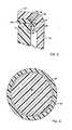
- Figure 1 is a partial sectional view showing a closure of this invention fitted to a container neck;
- Figure 2 is a partial sectional view of the closure shown in Figure 1 under the influence of a positive pressure in the container;
- Figure 3 is an enlarged sectional view of a portion of the container and closure shown in Figure 2;
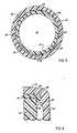
- Figure 4 is a sectional view taken along section lines 4-4 in Figure 1;
- Figure 5 is a sectional view taken along section lines 5-5 in Figure 2;
- Figure 6 is an enlarged sectional view showing a second embodiment of this invention.
- Referring now to Figures 1-4, it can be seen that a closure, generally designated by the numeral 10, is fitted to a container neck, generally designated by the numeral 8. Container neck 8 has about its outside surface adjacent its upper end
helical thread 26. At the terminal end of container neck 8 there is a mouth through which the container contents are dispensed.Lip 15 defines the boundaries of the container mouth. As mentioned previously, the container with which closure 10 is utilized can be made of any suitable material, e.g, glass or a thermoplastic material such as polyethylene terephthalate, polyethylene, polyvinyl chloride, etc. - Closure 10 has an annular
top wall 12 with asidewall 14 downwardly depending therefrom. About the inside surface ofsidewall 14 there is providedhelical closure thread 16 which is of a design whereby it cooperates with containerhelical thread 26 to achieve fitment of closure 10 to the container. In close proximity totop wall 12 there is providedliner 18.Liner 18 has a diameter greater than the outside diameter of container neck 8 measured at the container mouth. By having a greater diameter,line 18 will be able to extend around theoutside edge 28 oflip 15 to effect the seal of this invention.Liner 18 is prevented from moving away fromtop wall 12 by means ofannular ring 24.Annular ring 24 may be continuous or discontinuous. Attention is drawn to Figure 5 in which a discontinuousannular retaining ring 24 is shown. Projecting downwardly fromtop wall 12 there is providedannular tab 22.Annular tab 22 has a triangular shape when viewed in cross-section. See Figures 3, 6 and 7. As mentioned previously,annular tab 22 is utilized to insure thatliner 18 does not move laterally during the buildup of internal container pressure. Note thatannular tab 22 is positioned so that it is overlip 15. By havingannular tab 22 so positioned, it is assured thatannular tab 22 will obtain a grip onliner 18 by penetration. - Located adjacent the inside intersection of
top wall 12 and downwardlydeponding sidewall 14 there is providedannular bead 20. An enlarged view of the cross-section ofannular bead 20 is shown in Figure 3. As can be seen in this configuration,annular bead 20 has ahorizontal portion 21 and a vertical portion 23. Convex portion 25 connectshorizontal portion 21 to vertical portion 23. Convex portion 25 is preferably opposite theoutside edge 28 oflip 15. - In Figure 6, there is shown another configuration which may be utilized in place of
annular bead 20. In Figure 6,annular bead 40 is used in place ofannular bead 20.Annular bead 40 has, for all practical purposes, no horizontal or vertical portions, but rather is simply a convex bead. - Figures 3 and 6 show that the annular beads press against
liner 18 to cause it to wrap aroundoutside edge 28 oflip 15. Whentop wall 12 is flexed upwards due to pressure in the container the intersection oftop wall 12 andsidewall 14 is brought inwardly towardsoutside edge 28. As a result of this movement, the annular bead, since it is integral with the intersection, will also move inwardly towardsoutside edge 28. Thus,liner 18 is pressed by the annular bead so that it wraps aroundoutside edge 28. The greater the flexure of top wall 12the greater the inward movement of the before-mentioned intersection and the annular bead, and the further the annular bead is forced to move inwardly the greaterthe pressure it exerts onliner 18. It can therefore be seen that the seal betweenliner 18 andoutside edge 28 is increased as the pressure grows since the top wall flexes in response to the amount of pressure present.
Claims (10)
Applications Claiming Priority (4)
| Application Number | Priority Date | Filing Date | Title |
|---|---|---|---|
| US21873580A | 1980-12-22 | 1980-12-22 | |
| US218735 | 1980-12-22 | ||
| US27178181A | 1981-06-08 | 1981-06-08 | |
| US271781 | 1981-06-08 |
Publications (2)
| Publication Number | Publication Date |
|---|---|
| EP0055916A1 EP0055916A1 (en) | 1982-07-14 |
| EP0055916B1true EP0055916B1 (en) | 1990-09-12 |
Family
ID=26913194
Family Applications (2)
| Application Number | Title | Priority Date | Filing Date |
|---|---|---|---|
| EP19820900490WithdrawnEP0067221A1 (en) | 1980-12-22 | 1981-12-21 | Closure |
| EP19810306052Expired - LifetimeEP0055916B1 (en) | 1980-12-22 | 1981-12-22 | Closure |
Family Applications Before (1)
| Application Number | Title | Priority Date | Filing Date |
|---|---|---|---|
| EP19820900490WithdrawnEP0067221A1 (en) | 1980-12-22 | 1981-12-21 | Closure |
Country Status (7)
| Country | Link |
|---|---|
| EP (2) | EP0067221A1 (en) |
| JP (1) | JPS57501998A (en) |
| AU (2) | AU544147B2 (en) |
| BR (1) | BR8108921A (en) |
| CA (1) | CA1168621A (en) |
| DE (1) | DE3177214D1 (en) |
| WO (1) | WO1982002182A1 (en) |
Cited By (1)
| Publication number | Priority date | Publication date | Assignee | Title |
|---|---|---|---|---|
| DE19733636C2 (en)* | 1997-08-04 | 2000-12-14 | Weis Kg | Plastic screw cap |
Families Citing this family (13)
| Publication number | Priority date | Publication date | Assignee | Title |
|---|---|---|---|---|
| EP0067221A1 (en)* | 1980-12-22 | 1982-12-22 | Ethyl Products Company | Closure |
| US4381840A (en)* | 1981-08-24 | 1983-05-03 | Ethyl Products Company | Threaded closure with free-floating liner |
| GB2116529B (en)* | 1982-03-10 | 1985-07-17 | Grace W R & Co | Screw closure |
| ZA831232B (en)* | 1982-03-10 | 1983-11-30 | Grace W R & Co | Screw cap |
| AU533823B3 (en)* | 1983-06-23 | 1984-01-05 | Lilypak Limited | Improvements to plastic closures for carbonated beverages |
| GB2144110A (en)* | 1983-07-27 | 1985-02-27 | Metal Closures Ltd | Bottle closure |
| ATE44509T1 (en)* | 1984-10-19 | 1989-07-15 | Lynes Holding Sa | METHOD OF SEALING A CONTAINER. |
| DE3839351A1 (en)* | 1988-11-22 | 1990-05-31 | Berg Jacob Gmbh Co Kg | SCREW CAP FOR BOTTLES WITH VENTILATION DEVICE |
| FR2722764B1 (en)* | 1994-07-20 | 1996-10-04 | Rical Sa | SCREW SEALING CAPSULE |
| GB2321053A (en)* | 1997-01-08 | 1998-07-15 | Massmould Holdings | Screw cap with liner |
| EP0987191A1 (en) | 1998-09-14 | 2000-03-22 | Crown Cork & Seal Technologies Corporation | Closure cap |
| EP0987190A1 (en) | 1998-09-14 | 2000-03-22 | Crown Cork & Seal Technologies Corporation | Closure cap |
| FR2793216B1 (en)* | 1999-04-20 | 2001-06-08 | Pechiney Emballage Alimentaire | COMPOSITE CAPPING CAPSULE |
Citations (5)
| Publication number | Priority date | Publication date | Assignee | Title |
|---|---|---|---|---|
| US2409789A (en)* | 1943-09-21 | 1946-10-22 | Aluminum Co Of America | Method of sealing containers |
| US2409788A (en)* | 1942-10-21 | 1946-10-22 | Aluminum Co Of America | Method for applying closures to containers |
| US3207350A (en)* | 1961-10-20 | 1965-09-21 | Foster M Hagmann | Sealing closure for a crown-type bottle |
| GB1178447A (en)* | 1966-09-29 | 1970-01-21 | Grace W R & Co | Gasketed Closures for Containers. |
| GB1384370A (en)* | 1971-01-11 | 1975-02-19 | United Glass Ltd | Closures for containers |
Family Cites Families (15)
| Publication number | Priority date | Publication date | Assignee | Title |
|---|---|---|---|---|
| US2068389A (en)* | 1931-09-21 | 1937-01-19 | Anchor Cap & Closure Corp | Closure cap and liner therefor |
| US2130749A (en)* | 1931-09-21 | 1938-09-20 | Anchor Cap & Closure Corp | Cap and package |
| US2550586A (en)* | 1945-10-25 | 1951-04-24 | Sartorius & Co Inc A | Bottle, cap, and brush |
| GB683521A (en)* | 1946-11-27 | 1952-12-03 | Aluminum Co Of America | Improvements in or relating to closure blanks |
| DE875454C (en)* | 1951-03-06 | 1953-05-04 | Curt Albrecht | Closing cap for bottle-shaped container |
| US3067900A (en)* | 1960-07-28 | 1962-12-11 | Kessler Milton | Self-venting pressure-release sealing cap |
| US3331523A (en)* | 1965-02-15 | 1967-07-18 | Gilbert Mfg Company | Container closure member and liner therefor |
| US3462034A (en)* | 1967-08-25 | 1969-08-19 | Braun Co W | Means for closing and sealing a bottle or container |
| US3536224A (en)* | 1969-07-14 | 1970-10-27 | Kerr Glass Mfg Corp | Molded-in liner for a closure |
| DE2115824A1 (en)* | 1970-04-02 | 1971-10-21 | Grace W R & Co | Process for the production of seals in container closures |
| DE2137389A1 (en)* | 1971-07-26 | 1973-02-08 | Joseph William Dukess | CLOSURE |
| CH597052A5 (en)* | 1976-02-16 | 1978-03-31 | Brac Werke Ag | Plastics sealing disc for screw-on container closure |
| AU510121B2 (en)* | 1976-05-19 | 1980-06-12 | C. W Cooke | Safety cap and container neck |
| US4151924A (en)* | 1977-11-07 | 1979-05-01 | Owens-Illinois, Inc. | Liner element for closure cap |
| EP0067221A1 (en)* | 1980-12-22 | 1982-12-22 | Ethyl Products Company | Closure |
- 1981
- 1981-12-21EPEP19820900490patent/EP0067221A1/ennot_activeWithdrawn
- 1981-12-21WOPCT/US1981/001737patent/WO1982002182A1/enunknown
- 1981-12-21AUAU80835/82Apatent/AU544147B2/ennot_activeExpired
- 1981-12-21JPJP82500511Apatent/JPS57501998A/jaactivePending
- 1981-12-21BRBR8108921Apatent/BR8108921A/enunknown
- 1981-12-22CACA000392976Apatent/CA1168621A/ennot_activeExpired
- 1981-12-22DEDE8181306052Tpatent/DE3177214D1/ennot_activeExpired - Lifetime
- 1981-12-22EPEP19810306052patent/EP0055916B1/ennot_activeExpired - Lifetime
- 1985
- 1985-08-13AUAU46162/85Apatent/AU576885B2/ennot_activeExpired
Patent Citations (5)
| Publication number | Priority date | Publication date | Assignee | Title |
|---|---|---|---|---|
| US2409788A (en)* | 1942-10-21 | 1946-10-22 | Aluminum Co Of America | Method for applying closures to containers |
| US2409789A (en)* | 1943-09-21 | 1946-10-22 | Aluminum Co Of America | Method of sealing containers |
| US3207350A (en)* | 1961-10-20 | 1965-09-21 | Foster M Hagmann | Sealing closure for a crown-type bottle |
| GB1178447A (en)* | 1966-09-29 | 1970-01-21 | Grace W R & Co | Gasketed Closures for Containers. |
| GB1384370A (en)* | 1971-01-11 | 1975-02-19 | United Glass Ltd | Closures for containers |
Cited By (1)
| Publication number | Priority date | Publication date | Assignee | Title |
|---|---|---|---|---|
| DE19733636C2 (en)* | 1997-08-04 | 2000-12-14 | Weis Kg | Plastic screw cap |
Also Published As
| Publication number | Publication date |
|---|---|
| AU4616285A (en) | 1985-11-21 |
| CA1168621A (en) | 1984-06-05 |
| AU8083582A (en) | 1982-07-20 |
| BR8108921A (en) | 1982-11-30 |
| EP0055916A1 (en) | 1982-07-14 |
| AU544147B2 (en) | 1985-05-16 |
| AU576885B2 (en) | 1988-09-08 |
| DE3177214D1 (en) | 1990-10-18 |
| EP0067221A1 (en) | 1982-12-22 |
| WO1982002182A1 (en) | 1982-07-08 |
| JPS57501998A (en) | 1982-11-11 |
Similar Documents
| Publication | Publication Date | Title |
|---|---|---|
| US4462502A (en) | Threaded closure with liner | |
| EP0055916B1 (en) | Closure | |
| US4381840A (en) | Threaded closure with free-floating liner | |
| EP0140655B2 (en) | One-piece plastics closure | |
| EP0871585B1 (en) | Plastic lug closure | |
| US5259522A (en) | Linerless closure | |
| US4564117A (en) | Bottle closure | |
| US4209102A (en) | Linerless plastic closure | |
| US6102227A (en) | Snap-on cap with twist on/off reclosure lid | |
| US4629083A (en) | Closure with resilient sealing disc | |
| GB2120219A (en) | Containers | |
| EP0119055A2 (en) | Improvements relating to closures | |
| US4349116A (en) | Thermoplastic screw-threaded closure cap | |
| US4623070A (en) | Closure cap | |
| US4060172A (en) | Container and closure cap | |
| US4668458A (en) | Method of forming a carbonated beverage package | |
| US4498597A (en) | Container and closure | |
| US3022917A (en) | Threaded metal closure cap for a container | |
| US3235114A (en) | Jar seal | |
| US4610372A (en) | Self-sealing closure for small containers | |
| JP4392873B2 (en) | Plastic container lid | |
| US4303168A (en) | Linerless closure with crushable seal | |
| US3229842A (en) | Crown closure | |
| EP1621475B1 (en) | Closure for a container, especially a bottle | |
| US2974816A (en) | Closing and sealing bottles and other receptacles |
Legal Events
| Date | Code | Title | Description |
|---|---|---|---|
| PUAI | Public reference made under article 153(3) epc to a published international application that has entered the european phase | Free format text:ORIGINAL CODE: 0009012 | |
| AK | Designated contracting states | Designated state(s):BE DE FR GB IT NL | |
| 17P | Request for examination filed | Effective date:19830111 | |
| RAP1 | Party data changed (applicant data changed or rights of an application transferred) | Owner name:ETHYL MOLDED PRODUCTS COMPANY | |
| GRAA | (expected) grant | Free format text:ORIGINAL CODE: 0009210 | |
| AK | Designated contracting states | Kind code of ref document:B1 Designated state(s):BE DE FR GB IT NL | |
| ITF | It: translation for a ep patent filed | ||
| RAP4 | Party data changed (patent owner data changed or rights of a patent transferred) | Owner name:TREDEGAR MOLDED PRODUCTS COMPANY | |
| REF | Corresponds to: | Ref document number:3177214 Country of ref document:DE Date of ref document:19901018 | |
| ET | Fr: translation filed | ||
| PLBI | Opposition filed | Free format text:ORIGINAL CODE: 0009260 | |
| 26 | Opposition filed | Opponent name:DATREX AG, Effective date:19910513 | |
| NLR1 | Nl: opposition has been filed with the epo | Opponent name:DATREX AG. | |
| RAP4 | Party data changed (patent owner data changed or rights of a patent transferred) | Owner name:TREDEGAR MOLDED PRODUCTS COMPANY | |
| PLBM | Termination of opposition procedure: date of legal effect published | Free format text:ORIGINAL CODE: 0009276 | |
| STAA | Information on the status of an ep patent application or granted ep patent | Free format text:STATUS: OPPOSITION PROCEDURE CLOSED | |
| 27C | Opposition proceedings terminated | Effective date:19920510 | |
| ITTA | It: last paid annual fee | ||
| NLR2 | Nl: decision of opposition | ||
| NLT1 | Nl: modifications of names registered in virtue of documents presented to the patent office pursuant to art. 16 a, paragraph 1 | Owner name:TREDEGAR MOLDED PRODUCTS COMPANY TE RICHMOND, VIRG | |
| NLS | Nl: assignments of ep-patents | Owner name:CROWN CORK & SEAL COMPANY, INC. TE WILMINGTON, DEL | |
| BECA | Be: change of holder's address | Free format text:940707 *CROW CORK & SEAL CY (DELAWARE) INC.:103 SPRINGER BUILDING 3411 SILVERSIDE ROAD, WILMINGTON DELAWARE | |
| REG | Reference to a national code | Ref country code:FR Ref legal event code:TP | |
| PGFP | Annual fee paid to national office [announced via postgrant information from national office to epo] | Ref country code:NL Payment date:19991122 Year of fee payment:19 | |
| PGFP | Annual fee paid to national office [announced via postgrant information from national office to epo] | Ref country code:BE Payment date:19991208 Year of fee payment:19 | |
| PGFP | Annual fee paid to national office [announced via postgrant information from national office to epo] | Ref country code:FR Payment date:20001113 Year of fee payment:20 | |
| PGFP | Annual fee paid to national office [announced via postgrant information from national office to epo] | Ref country code:GB Payment date:20001120 Year of fee payment:20 | |
| PGFP | Annual fee paid to national office [announced via postgrant information from national office to epo] | Ref country code:DE Payment date:20001122 Year of fee payment:20 | |
| PG25 | Lapsed in a contracting state [announced via postgrant information from national office to epo] | Ref country code:BE Free format text:LAPSE BECAUSE OF NON-PAYMENT OF DUE FEES Effective date:20001231 | |
| BERE | Be: lapsed | Owner name:CROW CORK & SEAL CY (DELAWARE) INC. Effective date:20001231 | |
| PG25 | Lapsed in a contracting state [announced via postgrant information from national office to epo] | Ref country code:NL Free format text:LAPSE BECAUSE OF NON-PAYMENT OF DUE FEES Effective date:20010701 | |
| NLV4 | Nl: lapsed or anulled due to non-payment of the annual fee | Effective date:20010701 | |
| PG25 | Lapsed in a contracting state [announced via postgrant information from national office to epo] | Ref country code:GB Free format text:LAPSE BECAUSE OF EXPIRATION OF PROTECTION Effective date:20011221 | |
| REG | Reference to a national code | Ref country code:GB Ref legal event code:PE20 Effective date:20011221 |