EP0054156A1 - Device for filling boreholes - Google Patents
Device for filling boreholesDownload PDFInfo
- Publication number
- EP0054156A1 EP0054156A1EP81109033AEP81109033AEP0054156A1EP 0054156 A1EP0054156 A1EP 0054156A1EP 81109033 AEP81109033 AEP 81109033AEP 81109033 AEP81109033 AEP 81109033AEP 0054156 A1EP0054156 A1EP 0054156A1
- Authority
- EP
- European Patent Office
- Prior art keywords
- mouthpiece
- feed
- masses
- storage containers
- lever
- Prior art date
- Legal status (The legal status is an assumption and is not a legal conclusion. Google has not performed a legal analysis and makes no representation as to the accuracy of the status listed.)
- Granted
Links
Images

Classifications
- B—PERFORMING OPERATIONS; TRANSPORTING
- B05—SPRAYING OR ATOMISING IN GENERAL; APPLYING FLUENT MATERIALS TO SURFACES, IN GENERAL
- B05C—APPARATUS FOR APPLYING FLUENT MATERIALS TO SURFACES, IN GENERAL
- B05C17/00—Hand tools or apparatus using hand held tools, for applying liquids or other fluent materials to, for spreading applied liquids or other fluent materials on, or for partially removing applied liquids or other fluent materials from, surfaces
- B05C17/005—Hand tools or apparatus using hand held tools, for applying liquids or other fluent materials to, for spreading applied liquids or other fluent materials on, or for partially removing applied liquids or other fluent materials from, surfaces for discharging material from a reservoir or container located in or on the hand tool through an outlet orifice by pressure without using surface contacting members like pads or brushes
- B05C17/00553—Hand tools or apparatus using hand held tools, for applying liquids or other fluent materials to, for spreading applied liquids or other fluent materials on, or for partially removing applied liquids or other fluent materials from, surfaces for discharging material from a reservoir or container located in or on the hand tool through an outlet orifice by pressure without using surface contacting members like pads or brushes with means allowing the stock of material to consist of at least two different components
- B—PERFORMING OPERATIONS; TRANSPORTING
- B05—SPRAYING OR ATOMISING IN GENERAL; APPLYING FLUENT MATERIALS TO SURFACES, IN GENERAL
- B05C—APPARATUS FOR APPLYING FLUENT MATERIALS TO SURFACES, IN GENERAL
- B05C17/00—Hand tools or apparatus using hand held tools, for applying liquids or other fluent materials to, for spreading applied liquids or other fluent materials on, or for partially removing applied liquids or other fluent materials from, surfaces
- B05C17/005—Hand tools or apparatus using hand held tools, for applying liquids or other fluent materials to, for spreading applied liquids or other fluent materials on, or for partially removing applied liquids or other fluent materials from, surfaces for discharging material from a reservoir or container located in or on the hand tool through an outlet orifice by pressure without using surface contacting members like pads or brushes
- B05C17/00503—Details of the outlet element
- B05C17/00516—Shape or geometry of the outlet orifice or the outlet element
- B—PERFORMING OPERATIONS; TRANSPORTING
- B05—SPRAYING OR ATOMISING IN GENERAL; APPLYING FLUENT MATERIALS TO SURFACES, IN GENERAL
- B05C—APPARATUS FOR APPLYING FLUENT MATERIALS TO SURFACES, IN GENERAL
- B05C17/00—Hand tools or apparatus using hand held tools, for applying liquids or other fluent materials to, for spreading applied liquids or other fluent materials on, or for partially removing applied liquids or other fluent materials from, surfaces
- B05C17/005—Hand tools or apparatus using hand held tools, for applying liquids or other fluent materials to, for spreading applied liquids or other fluent materials on, or for partially removing applied liquids or other fluent materials from, surfaces for discharging material from a reservoir or container located in or on the hand tool through an outlet orifice by pressure without using surface contacting members like pads or brushes
- B05C17/00596—The liquid or other fluent material being supplied from a rigid removable cartridge having no active dispensing means, i.e. the cartridge requiring cooperation with means of the handtool to expel the material
- B—PERFORMING OPERATIONS; TRANSPORTING
- B05—SPRAYING OR ATOMISING IN GENERAL; APPLYING FLUENT MATERIALS TO SURFACES, IN GENERAL
- B05C—APPARATUS FOR APPLYING FLUENT MATERIALS TO SURFACES, IN GENERAL
- B05C17/00—Hand tools or apparatus using hand held tools, for applying liquids or other fluent materials to, for spreading applied liquids or other fluent materials on, or for partially removing applied liquids or other fluent materials from, surfaces
- B05C17/005—Hand tools or apparatus using hand held tools, for applying liquids or other fluent materials to, for spreading applied liquids or other fluent materials on, or for partially removing applied liquids or other fluent materials from, surfaces for discharging material from a reservoir or container located in or on the hand tool through an outlet orifice by pressure without using surface contacting members like pads or brushes
- B05C17/01—Hand tools or apparatus using hand held tools, for applying liquids or other fluent materials to, for spreading applied liquids or other fluent materials on, or for partially removing applied liquids or other fluent materials from, surfaces for discharging material from a reservoir or container located in or on the hand tool through an outlet orifice by pressure without using surface contacting members like pads or brushes with manually mechanically or electrically actuated piston or the like
- B05C17/0116—Hand tools or apparatus using hand held tools, for applying liquids or other fluent materials to, for spreading applied liquids or other fluent materials on, or for partially removing applied liquids or other fluent materials from, surfaces for discharging material from a reservoir or container located in or on the hand tool through an outlet orifice by pressure without using surface contacting members like pads or brushes with manually mechanically or electrically actuated piston or the like characterised by the piston driving means
- B05C17/012—Stepwise advancing mechanism, e.g. pawl and ratchets
- B05C17/0123—Lever actuated
- B05C17/0126—Lever actuated comprising an element, e.g. an arc compensating element, articulated at one end on the lever and at the other end on the piston rod driving means, e.g. a pawl
Definitions
- the inventionrelates to a device for filling boreholes by means of one- or multi-component adhesive, filling, sealing or filling compounds, with storage containers for the masses to be filled, a dispensing device and a pressing device which can be interacted with a hand lever for supplying the masses from the storage containers to the delivery facility.
- a measured amount of a hardening massis packaged in a destructible envelope.
- This packagingis inserted into the borehole and destroyed using the anchor rod in the borehole.
- This methodis relatively complex, in particular from the point of view of the necessary packaging, and therefore leads to high costs.
- the packagingleads to problems since it can be damaged outside the borehole prematurely, for example during transport or handling, and can therefore become unusable.
- the massis introduced into the borehole by means of a device consisting of large storage containers which generally contain the mass for several boreholes.
- a devicewhich consists of a tube which can be filled with the mass and which can be inserted so deeply into the borehole that its mouth lies against the bottom of the borehole. While withdrawing the pipe from the borehole, its content is pressed out by means of a piston which can be displaced in the pipe.
- This methodis extremely cumbersome due to the tube that has to be refilled before each insertion process and is associated with contamination due to dripping mass.
- the retraction of the tubeis completely left to the operator's hand, which allows the retraction to be carried out too quickly, possibly causing air pockets.
- the inventionhas for its object to provide a device that enables a clean, air-free filling of the borehole.
- the dispensing devicehas a feed nozzle and a mouthpiece, the feed nozzle being connected to the device and, viewed in the dispensing direction, the mouthpiece adjoining the feed nozzle and insertable into the boreholes, while dispensing the masses by means of an actuating device is telescopically displaceable against the feed pipe.
- the displacement of the mouthpieceis coupled with the delivery of the masses. It can thus be achieved that the mouthpiece is only pulled out of the borehole to the extent that it is already filled with the mass.
- the mouthpiececan be inserted into the feed nozzle or can include it. "In the latter case, the feed nozzle filled with mass serves as an ejection piston for the mouthpiece. If the mouthpiece is inserted into the inlet connector, the mouthpiece serves as an ejection piston.
- the massis brought from the storage containers into the dispensing device by means of the squeezing device.
- the channelscan be designed as tubular connecting pieces or as recesses in the housing.
- the channels opening from the storage containers into the supply connection piececan be arranged as desired. From a fluidic point of view, however, it is expedient if the channels open essentially radially into the feed connector.
- the components stored separately in the storage containersmust be mixed with one another before being introduced into the borehole.
- a radial flow of the channels into the feed connectorcreates a mixed flow in the feed connector.
- the channelscan be arranged opposite one another or adjacent to one another. In both cases, the flow results in a good mixture of the components. In order to improve this mixture even further, additional baffles serving to deflect the flow can be arranged in the feed connection.
- the massesare filled into the boreholes.
- the mouthpieceis tubular.
- the outside diameter of the mouthpiececan essentially correspond to the borehole diameter.
- the mouthpiecescan be exchanged for different borehole diameters.
- the individual componentswhen using multi-component materials, the individual components must be mixed with one another before being introduced into the borehole.
- the mouthpieceIn order to achieve thorough mixing, it is therefore expedient for the mouthpiece to contain a mixing insert. Due to the mixing insert, the components are broken down into partial streams when they flow through the mouthpiece and brought together again. If this is done several times in succession, the components are mixed homogeneously. If the components that have been mixed together harden in the area of the mixing insert after a long interruption in operation, the mixing insert, possibly together with the mouthpiece, can simply be replaced.
- the mouthpieceAfter the mouthpiece has been inserted into the borehole, the mouthpiece is pulled out of the borehole while the masses are being dispensed by means of the actuating device.
- the actuating deviceis designed as a feed unit that can be connected to the hand lever.
- the feed unitcan consist, for example, of a toothed rack and a latching lug interacting with it.
- a simple clamping deviceis also possible.
- the connection of the actuating device to the hand leverenables a gear ratio that is adapted to the conditions. Since the effort to pull back the mouthpiece is relatively small, this ratio can be chosen to be relatively large, so that only a few strokes of the hand lever are required to pull back the mouthpiece.
- the feed nozzle and the mouthpieceare to be filled on the one hand by means of the squeezing direction and on the other hand the mouthpiece is to be withdrawn by means of the actuating device. Since these two functions are to be carried out at different times, it is expedient that a switchover device is provided for the mutual transmission of the movement of the hand lever to the actuating device and to the squeezing device. Depending on the position, the switching device enables one or the other function to be carried out. The hand lever does not have to be released.
- the switching path required for switchingis relatively short. However, various spring forces must be overcome.
- the switching deviceis designed as an eccentric lever.
- An eccentric leverrequires simple turning as a switching movement.
- the switching devicecan be designed so that it is automatically locked in the end positions and no special holding elements are required.
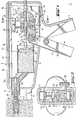
- the device according to the inventionwhich can be seen in FIGS. 1 to 4, is used to fill a borehole 1 in a receiving material 2.
- the devicehas a housing, which is denoted overall by 3.
- the housing 3consists of a rear part 3a receiving the drive mechanism and a front part 3c releasably connected thereto via a snap lock 3b.
- a handle 4is formed on the rear part 3a.
- the front part 3chas a stop 5 for supporting the device on the receiving material 2.
- two storage containers, generally designated 6,are arranged side by side for receiving the masses to be filled.
- a piston 6ais slidably guided in each of the storage containers 6.
- the plunger 7has a shaft 7a which is provided with tooth catches 7b.
- the front end of the plunger 7is designed in a manner known per se as a cutting edge 7c for cutting through the wall of the storage container 6.
- a hand lever 8 arranged in the area of the handle 4is rotatably mounted about an axis 9.
- the hand lever 8is brought into the illustrated starting position by a torsion spring 10.
- a pawl 11is pivotally connected to the hand lever 8 via an eccentrically arranged pin 12. In the position shown in FIG. 1, the pawl 11 is brought into engagement with the toothed catches 7b of the plunger 7 by means of a ball 13 supported on the housing 3 and a spring 14.
- a locking cam 15is also due to the force of a compression spring 16 in engagement with the tooth pegs 7b.
- the locking cam 15prevents the plunger 7 from being pushed back when the pawl 11 grips.
- a feed pipeIn the front part of the housing 3c there is also a feed pipe, designated overall by 17.
- the feed connector 17is connected to the storage containers 6 via channels 18.
- the channels 18open essentially radially into the feed connector 17.
- Baffles 17aare arranged in the rear region of the feed connector 17.
- the baffles 17aresult a good mixing of the u drunkstutzen of the hoppers 6 into the Z 17 flowing components.
- a mouthpiece, designated overall by 19,is telescopically displaceable relative to the feed connector 17.
- a mixing insert 20is arranged therein.
- the mouthpiece 19is retracted by an actuating device which essentially consists of a toothed rack 21 connected to the mouthpiece 19 and a latching lever 22 which can be brought into engagement with the toothed rack 21.
- the locking lever 22is also articulated on the hand lever 8.
- the locking lever 22is pressed against the rack 21 by a leaf spring 23.
- a locking lever 24is provided in order to avoid advancing the toothed rack 21 when the locking lever 22 is gripped.
- the locking lever 24is pivotally mounted about a pin 25 and is also pressed against the rack 21 by means of the compression spring 16.
- a total of 26 eccentric leverserves as a switching device.
- the eccentric lever 26has an eccentrically arranged pin 26a. In the position shown in FIGS.
- the pin 26apresses on the locking lever 22 and brings it out of engagement with the rack 21 against the force of the leaf spring 23.
- the locking lever 24is connected to the pin 26a via a linkage 27 and is also kept out of engagement with the rack 21.
- the pawl 11, on the other hand,is in engagement with the tooth catches 7b of the plunger 7.
- the mouthpiece 19 and the associated rack 21can move freely and, that is displaced by the inflowing 17 in the Z uzhoustutzen mass up to the stop of the rack 21 on the feed pipe 17 to the left against the receiving material. 2
- the housing front part 3ccan be removed for replacing or filling the storage container 6.
- the cross section shown in FIG. 2 through the housing rear part 3ashows the plunger 7 and the pawl 11 which is in engagement therewith and the locking cam 15.
- the rack 21, which is U-shaped in cross sectioncan be seen.
- the locking lever 22, which is also U-shaped in cross sectionis arranged.
- This designenables a partial nesting of the pawl 11 and the locking lever 22 and thus results in a compact design.
- the leaf spring 23is connected to the locking lever 22.
- the locking lever 22is pressed down by the pin 26a of the eccentric lever 26 against the force of the leaf spring 23.
- the pawl 11, however,is freely movable upwards.
- the locking lever 24is also pressed down against the force of the compression spring 16 and thus kept out of engagement with the rack 21.
- FIG. 3shows the device according to FIG. 1 while the mouthpiece 19 is being pulled back.
- the pin 26a eccentrically arranged on the eccentric lever 26moves upward, ie away from the handle 4.
- the pin 26apresses on the pawl 11 and, against the force of the spring 14 supported on the ball 13, disengages it from the toothed catches 7b of the plunger 7.
- the detent lever 22 and the locking lever 24, on the other hand,are released and pass through the force of the leaf spring 23 or the compression spring 16 in engagement with the rack 21.
- the hand lever 8is actuated, the rack 21 and the mouthpiece 19 connected to it become closed withdrawn.
- the mouthpiece 19has already been pulled out of the borehole 1 by the path s. A corresponding part of the mass was ejected into the borehole 1 by means of the mouthpiece 19 acting as a piston through its bores 19a and the mixing insert 20.
- the stop 5serves to support the device on the receiving material 2.
- the mass contained in the feed connector 17is displaced as far as possible through the mouthpiece 19 and ejected into the borehole 1 .
- the eccentric lever 26is then brought back into the position shown in FIGS. 1 and 2.
- the locking lever 22 and the locking lever 24come out of engagement with the rack 21 and the pawl 11 engages again in the tooth catches 7b of the plunger 7.
- the filling of the feed connector 17can thus begin again.
- the mouthpiece 19 together with the toothed rack 21is brought back into the position shown in FIG. 1.
- This filling of the feed connector 17can take place while the device is inserted with its mouthpiece 19 into a new borehole 1.
- a mouthpiece 19comprising the feed nozzle 17 can also be provided.
- the feed connector 17 with the mass contained thereinserves as an ejection piston for pressing the mass out of the mouthpiece 19.
- the cross section through the device shown in FIG. 4shows the two storage containers 6 arranged next to one another. From the storage containers 6, channels 18 lead into the supply nozzle 17. As the figure shows, the channels 18 open essentially radially into the supply nozzle 17. In the housing Front part 3c also shows the rack 21 connected to the rearward extension of the mouthpiece 19.
Landscapes
- Engineering & Computer Science (AREA)
- Mechanical Engineering (AREA)
- Physics & Mathematics (AREA)
- Geometry (AREA)
- Coating Apparatus (AREA)
- Package Specialized In Special Use (AREA)
Abstract
Translated fromGerman
Description
Translated fromGermanDie Erfindung betrifft ein Gerät zum Verfüllen von Bohrlöchern mittels Ein- oder Mehrkomponenten-Klebe-, Füll-, Dicht- oder Spachtelmassen, mit Vorratsbehältern für die zu verfüllenden Massen, einer Abgabeeinrichtung und einer mit einem Handhebel zusammenwirkbaren Auspresseinrichtung zum Zuführen der Massen von den Vorratsbehältern in die Abgabeeinrichtung.The invention relates to a device for filling boreholes by means of one- or multi-component adhesive, filling, sealing or filling compounds, with storage containers for the masses to be filled, a dispensing device and a pressing device which can be interacted with a hand lever for supplying the masses from the storage containers to the delivery facility.
Zum Setzen von Ankern, bei denen eine bestimmte Menge aushärtender Masse zum Verankern einer Ankerstange ins Bohrloch eingebracht wird, haben sich in der Praxis grundsätzlich zwei Möglichkeiten durchgesetzt.In practice, two options have generally become established for setting anchors in which a certain amount of hardening mass is introduced into the borehole for anchoring an anchor rod.
Nach einer ersten Methode wird eine abgemessene Menge einer aushärtenden Masse in eine zerstörbare Umhüllung verpackt. Diese Verpackung wird ins Bohrloch eingeführt und mittels der Ankerstange im Bohrloch zerstört. Diese Methode ist insbesondere aus der Sicht der notwendigen Verpackungen relativ aufwendig und führt damit zu hohen Kosten. Ausserdem führen die Verpackungen zu Problemen, da sie vorzeitig, beispielsweise beim Transport oder bei der Handhabung, ausserhalb des Bohrloches beschädigt und somit unbrauchbar werden können.According to a first method, a measured amount of a hardening mass is packaged in a destructible envelope. This packaging is inserted into the borehole and destroyed using the anchor rod in the borehole. This method is relatively complex, in particular from the point of view of the necessary packaging, and therefore leads to high costs. In addition, the packaging leads to problems since it can be damaged outside the borehole prematurely, for example during transport or handling, and can therefore become unusable.
Nach der zweiten Methode wird die Masse mittels eines Gerätes aus grossen, in der Regel die Masse für mehrere Bohrlöcher enthaltenden Vorratsbehältern ins Bohrloch eingebracht. Dabei entsteht insbesondere das Problem, dass beim Füllen des Bohrloches den Auszugswert der Verankerung herabsetzende Lufteinschlüsse entstehen können. Zur Vermeidung solcher Lufteinschlüsse ist eine Vorrichtung bekannt, die aus einem mit der Masse füllbaren Rohr besteht, das so tief ins Bohrloch eingesetzt werden kann, dass es mit seiner Mündung am Bohrlochgrund ansteht. Unter Zurückziehen des Rohres aus dem Bohrloch wird dessen Inhalt mittels eines im Rohr verschiebbaren Kolbens ausgepresst. Diese Methode ist aufgrund des vor jedem Einbringvorgang neu zu füllenden Rohres höchst umständlich und mit Verschmutzungen durch tropfende Masse verbunden. Ueberdies ist das Zurückziehen des Rohres vollkommen der Handhabung der Bedienungsperson überlassen, was ein zu schnelles, unter Umständen Lufteinschlüsse herbeiführendes Zurückziehen erlaubt.According to the second method, the mass is introduced into the borehole by means of a device consisting of large storage containers which generally contain the mass for several boreholes. In particular, this creates the problem that air pockets can reduce the extraction value of the anchoring when the borehole is filled. To avoid such air pockets, a device is known which consists of a tube which can be filled with the mass and which can be inserted so deeply into the borehole that its mouth lies against the bottom of the borehole. While withdrawing the pipe from the borehole, its content is pressed out by means of a piston which can be displaced in the pipe. This method is extremely cumbersome due to the tube that has to be refilled before each insertion process and is associated with contamination due to dripping mass. In addition, the retraction of the tube is completely left to the operator's hand, which allows the retraction to be carried out too quickly, possibly causing air pockets.
Der Erfindung liegt die Aufgabe zugrunde, eine Vorrichtung zu schaffen, die ein sauberes, luftfreies Füllen des Bohrloches ermöglicht.The invention has for its object to provide a device that enables a clean, air-free filling of the borehole.
Gemäss der Erfindung wird dies dadurch erreicht, dass die Abgabeeinrichtung einen Zuführstutzen und ein Mundstück aufweist, wobei der Zuführstutzen mit dem Gerät verbunden ist und das, in Abgaberichtung gesehen, an den Zuführstutzen anschliessende, in die Bohrlöcher einführbare Mundstück unter Abgeben der Massen mittels einer Betätigungseinrichtung teleskopartig gegen den Zuführstutzen verschiebbar ist.According to the invention, this is achieved in that the dispensing device has a feed nozzle and a mouthpiece, the feed nozzle being connected to the device and, viewed in the dispensing direction, the mouthpiece adjoining the feed nozzle and insertable into the boreholes, while dispensing the masses by means of an actuating device is telescopically displaceable against the feed pipe.
Durch die erfindungsgemässe Ausbildung wird das Verschieben des Mundstückes mit dem Abgeben der Massen gekoppelt. Somit kann erreicht werden, dass das Mundstück nur soweit aus dem Bohrloch herausgezogen wird, als dieses bereits mit der Masse gefüllt ist. Das Mundstück kann in den Zuführstutzen eingeführt werden oder kann diesen umfassen." In letzterem Fall dient der mit Masse gefüllte Zuführstutzen als Auspresskolben für das Mundstück. Wird das Mundstück in den Zuführstutzen eingeführt, so dient das Mundstück als Auspresskolben.Due to the inventive design, the displacement of the mouthpiece is coupled with the delivery of the masses. It can thus be achieved that the mouthpiece is only pulled out of the borehole to the extent that it is already filled with the mass. The mouthpiece can be inserted into the feed nozzle or can include it. "In the latter case, the feed nozzle filled with mass serves as an ejection piston for the mouthpiece. If the mouthpiece is inserted into the inlet connector, the mouthpiece serves as an ejection piston.
Die Masse wird mittels der Auspresseinrichtung von den Vorratsbehältern in die Abgabeeinrichtung gebracht. Zu diesem Zweck ist es vorteilhaft, dass von den Vorratsbehältern in den Zuführstutzen mündende Kanäle vorgesehen sind. Die Kanäle können als rohrförmige Verbindungsstücke oder als Ausnehmungen im Gehäuse ausgebildet werden.The mass is brought from the storage containers into the dispensing device by means of the squeezing device. For this purpose, it is advantageous that channels opening from the storage containers into the feed connection are provided. The channels can be designed as tubular connecting pieces or as recesses in the housing.
Die von den Vorratsbehältern in den Zuführstutzen mündenden Kanäle können im Prinzip beliebig angeordnet werden. Aus strömungstechnischer Sicht ist es jedoch zweckmässig, wenn die Kanäle im wesentlichen radial in den Zuführstutzen münden. Die in den Vorratsbehältern getrennt gelagerten Komponenten müssen vor dem Einbringen in das Bohrloch miteinander vermischt werden. Durch ein radiales Einmünden der Kanäle in den Zuführstutzen entsteht im Zuführstutzen eine Mischströmung. Die Kanäle können einander gegenüberliegend oder aneinander angrenzend angeordnet sein. In beiden Fällen ergibt sich durch die Strömung eine gute Mischung der Komponenten. Um diese Mischung noch zu verbessern, können ausserdem im Zuführstutzen zusätzliche, dem Umlenken der Strömung dienende Leitbleche angeordnet werden.In principle, the channels opening from the storage containers into the supply connection piece can be arranged as desired. From a fluidic point of view, however, it is expedient if the channels open essentially radially into the feed connector. The components stored separately in the storage containers must be mixed with one another before being introduced into the borehole. A radial flow of the channels into the feed connector creates a mixed flow in the feed connector. The channels can be arranged opposite one another or adjacent to one another. In both cases, the flow results in a good mixture of the components. In order to improve this mixture even further, additional baffles serving to deflect the flow can be arranged in the feed connection.
Mit Hilfe des Mundstücks werden die Massen in die Bohrlöcher eingefüllt. Um das Bohrlochtiefste zu erreichen, ist es vorteilhaft, dass das Mundstück rohrförmig ausgebildet ist. Der Aussendurchmesser des Mundstücks kann dabei im wesentlichen dem Bohrlochdurchmesser entsprechen. Für verschiedene Bohrlochdurchmesser können die Mundstücke ausgewechselt werden.With the help of the mouthpiece, the masses are filled into the boreholes. In order to reach the deepest hole, it is advantageous that the mouthpiece is tubular. The outside diameter of the mouthpiece can essentially correspond to the borehole diameter. The mouthpieces can be exchanged for different borehole diameters.
Wie bereits erwähnt, müssen bei Verwendung von Mehrkomponentenmassen die einzelnen Komponenten vor dem Einbringen ins Bohrloch miteinander vermischt werden. Um eine gute Durchmischung zu erreichen, ist es daher zweckmässig, dass das Mundstück einen Mischeinsatz enthält. Durch den Mischeinsatz werden die Komponenten beim Durchströmen des Mundstücks mittels Schikanen in Teilströme zerlegt und wieder zusammengeführt. Erfolgt dies mehrmals hintereinander, so ergibt sich eine homogene Mischung der Komponenten. Wenn nach einem längeren Betriebsunterbruch die miteinander vermischten Komponenten im Bereich des Mischeinsatzes aushärten, kann der Mischeinsatz, eventuell mitsamt dem Mundstück, einfach ausgewechselt werden.As already mentioned, when using multi-component materials, the individual components must be mixed with one another before being introduced into the borehole. In order to achieve thorough mixing, it is therefore expedient for the mouthpiece to contain a mixing insert. Due to the mixing insert, the components are broken down into partial streams when they flow through the mouthpiece and brought together again. If this is done several times in succession, the components are mixed homogeneously. If the components that have been mixed together harden in the area of the mixing insert after a long interruption in operation, the mixing insert, possibly together with the mouthpiece, can simply be replaced.
Nach dem Einführen des Mundstücks in das Bohrloch wird das Mundstück unter Abgeben der Massen mittels der Betätigungseinrichtung aus dem Bohrloch herausgezogen. Um nun ein möglichst gleichmässiges Herausziehen des Mundstücks zu erreichen, ist es vorteilhaft, dass die Betätigungseinrichtung als mit dem Handhebel in Verbindung bringbare Vorschubeinheit ausgebildet ist. Die Vorschubeinheit kann beispielsweise aus einer Zahnstange und einer mit dieser zusammenwirkenden Rastnase bestehen. Daneben ist jedoch auch eine einfache Klemmeinrichtung möglich. Das Verbinden der Betätigungseinrichtung mit dem Handhebel ermöglicht eine den Verhältnissen angepasste Uebersetzung. Da der Kraftaufwand zum Zurückziehen des Mundstücks relativ gering ist, kann diese Uebersetzung verhältnismässig gross gewählt werden, so dass für das Zurückziehen des Mundstücks nur wenige Hübe des Handhebels erforderlich sind.After the mouthpiece has been inserted into the borehole, the mouthpiece is pulled out of the borehole while the masses are being dispensed by means of the actuating device. In order to pull out the mouthpiece as uniformly as possible, it is advantageous that the actuating device is designed as a feed unit that can be connected to the hand lever. The feed unit can consist, for example, of a toothed rack and a latching lug interacting with it. In addition, however, a simple clamping device is also possible. The connection of the actuating device to the hand lever enables a gear ratio that is adapted to the conditions. Since the effort to pull back the mouthpiece is relatively small, this ratio can be chosen to be relatively large, so that only a few strokes of the hand lever are required to pull back the mouthpiece.
Beim Verarbeiten der Massen mittels des erfindungsgemässen Gerätes ist zum einen mittels der Auspressrichtung der Zuführstutzen sowie das Mundstück zu füllen und zum anderen das Mundstück mittels der Betätigungseinrichtung zurückzuziehen. Da diese beiden Funktionen zeitlich getrennt auszuführen sind, ist es zweckmässig, dass eine Umschalteinrichtung zur wechselseitigen Uebertragung der Bewegung des Handhebels auf die Betätigungseinrichtung und auf die Auspresseinrichtung vorgesehen ist. Je nach Stellung ermöglicht die Umschalteinrichtung das Ausführen der einen oder der anderen Funktion. Der Handhebel muss dabei nicht losgelassen werden.When processing the masses by means of the device according to the invention, the feed nozzle and the mouthpiece are to be filled on the one hand by means of the squeezing direction and on the other hand the mouthpiece is to be withdrawn by means of the actuating device. Since these two functions are to be carried out at different times, it is expedient that a switchover device is provided for the mutual transmission of the movement of the hand lever to the actuating device and to the squeezing device. Depending on the position, the switching device enables one or the other function to be carried out. The hand lever does not have to be released.
Der zum Umschalten erforderliche Schaltweg ist relativ gering. Dabei müssen jedoch verschiedene Federkräfte überwunden werden. Um ein einfaches Umschalten zu ermöglichen, ist es vorteilhaft, dass die Umschalteinrichtung als Exzenterhebel ausgebildet ist. Ein Exzenterhebel erfordert ein einfaches Drehen als Schaltbewegung. Durch günstiges Festlegen der Exzentrizität, bzw des Schaltwinkels kann die Umschalteinrichtung so ausgelegt werden, dass sie in den Endstellungen selbsttätig verriegelt wird und keine besonderen Halteelemente benötigt werden.The switching path required for switching is relatively short. However, various spring forces must be overcome. In order to enable simple switching, it is advantageous that the switching device is designed as an eccentric lever. An eccentric lever requires simple turning as a switching movement. By advantageously setting the eccentricity or the switching angle, the switching device can be designed so that it is automatically locked in the end positions and no special holding elements are required.
Die Erfindung soll nachstehend anhand der sie beispielsweise wiedergebenden Zeichnungen näher erläutert werden. Es zeigen:
- Fig. 1 Einen Schnitt durch ein erfindungsgemässes Gerät, beim Betätigen der Auspresseinrichtung,
- Fig. 2 einen Querschnitt durch das Gerät gemäss Fig. 1, entlang der Linie II-II,
- Fig. 3 einen Schnitt durch das Gerät entsprechend Fig. 1, während des Zurückziehens des Mundstücks,
- Fig. 4 einen Querschnitt durch das in Fig. 3 dargestellte Gerät, entlang der Linie IV-IV.
- 1 shows a section through a device according to the invention when the squeezing device is actuated,
- 2 shows a cross section through the device according to FIG. 1, along the line II-II,
- 3 shows a section through the device corresponding to FIG. 1 while the mouthpiece is being withdrawn, FIG.
- Fig. 4 shows a cross section through the device shown in Fig. 3, along the line IV-IV.
Das aus den Figuren 1 bis 4 ersichtliche, erfindungsgemässe Gerät dient zum Füllen eines Bohrloches 1 in einem Aufnahmematerial 2. Das Gerät weist ein insgesamt mit 3 bezeichnetes Gehäuse auf. Das Gehäuse 3 besteht aus einem den Antriebsmechanismus aufnehmenden Hinterteil 3a und einem damit über einen Rastverschluss 3b lösbar verbundenen Vorderteil 3c. Am Hinterteil 3a ist ein Handgriff 4 angeformt. Das Vorderteil 3c weist einen Anschlag 5 zum Abstützen des Gerätes auf dem Aufnahmematerial 2 auf. Im Gehäuse 3 sind nebeneinander liegend zwei insgesamt mit 6 bezeichnete Vorratsbehälter zur Aufnahme der zu verfüllenden Massen angeordnet. In den Vorratsbehältern 6 ist je ein Kolben 6a verschiebbar geführt. Ein insgesamt mit 7 bezeichneter Stössel drückt auf die Kolben 6a. Der Stössel 7 weist einen Schaft 7a auf, der'mit Zahnrasten 7b versehen ist. Das vordere Ende des Stössels 7 ist in an sich bekannter Weise als Schneide 7c zum Durchtrennen der Wandung des Vorratsbehälters 6 ausgebildet. Ein im Bereich des Handgriffs 4 angeordneter Handhebel 8 ist um eine Achse 9 drehbar gelagert. Der Handhebel 8 wird durch eine Torsionsfeder 10 in die dargestellte Ausgangslage gebracht. Eine Klinke 11 ist über einen exzentrisch angeordneten Zapfen 12 mit dem Handhebel 8 schwenkbar verbunden. In der in Fig. 1 dargestellten Stellung wird die Klinke 11 mittels einer sich auf dem Gehäuse 3 abstützenden Kugel 13 und einer Feder 14 mit den Zahnrasten 7b des Stössels 7 in Eingriff gebracht. Beim Betätigen des Handhebels 8 wird somit der Stössel 7 und mit diesem der Kolben 6a in Richtung des Anschlages 5 transportiert. Ein Sperrnocken 15 steht infolge der Kraft einer Druckfeder 16 ebenfalls in Eingriff mit den Zahnrasten 7b.The device according to the invention, which can be seen in FIGS. 1 to 4, is used to fill a
Der Sperrnocken 15 verhindert das Zurückschieben des Stössels 7 beim Nachgreifen der Klinke 11.The locking
Im Gehäusevorderteil 3c ist weiterhin ein insgesamt mit 17 bezeichneter Zuführstutzen angeordnet. Der Zuführstutzen 17 steht über Kanäle 18 in Verbindung mit den Vorratsbehältern 6. Die Kanäle 18 münden im wesentlichen radial in den Zuführstutzen 17. Im rückwärtigen Bereich des Zuführstutzens 17 sind Leitbleche 17a angeordnet. Die Leitbleche 17a ergeben eine gute Durchmischung der von den Vorratsbehältern 6 in denZuführstutzen 17 strömenden Komponenten. Ein insgesamt mit 19 bezeichnetes Mundstück ist gegenüber dem Zuführstutzen 17 teleskopartig verschiebbar. Beim Betätigen der im wesentlichen aus dem Stössel 7 und der Klinke 11 bestehendenAuspresseinrichtung durch den Handhebel 8 wird ein Teil der Masse aus den Vorratsbehältern 6 verdrängt und gelangt durch die Kanäle 18 in den Zuführstutzen 17. Durch die in den Zuführstutzen 17 einströmende Masse wird dabei das Mundstück 19 in Richtung des Aufnahmematerials 2 in die in Fig. 1 dargestellte Lage verschoben. Zum weiteren Mischen der Komponenten beim Durchströmen des Mundstückes 19 ist in diesem ein Mischeinsatz 20 angeordnet.In the front part of the
Das Zurückziehen des Mundstückes 19 erfolgt durch eine Betätigungseinrichtung, die im wesentlichen aus einer mit dem Mundstück 19 in Verbindung stehenden Zahnstange 21 und einem mit der Zahnstange 21 in Eingriff bringbaren Rasthebel 22 besteht. Der Rasthebel 22 ist ebenfalls am Handhebel 8 angelenkt. Der Rasthebel 22 wird durch eine Blattfeder 23.gegen die Zahnstange 21 gedrückt. Um beim Nachgreifen des Rasthebels 22 ein Vorschieben der Zahnstange 21 zu vermeiden, ist ein Sperrhebel 24 vorgesehen. Der Sperrhebel 24 ist um einen Stift 25 schwenkbar gelagert und wird mittels der Druckfeder 16 ebenfalls gegen die Zahnstange 21 gedrückt. Ein insgesamt mit 26 bezeichneter Exzenterhebel dient als Umschalteinrichtung. Der Exzenterhebel 26 weist einen exzentrisch angeordneten Zapfen 26a auf. In der in den Fig. 1 und 2 dargestellten Stellung drückt der Zapfen 26a auf den Rasthebel 22 und bringt diesen gegen die Kraft der Blattfeder 23 ausser Eingriff mit der Zahnstange 21. Der Sperrhebel 24 steht über ein Gestänge 27 mit dem Zapfen 26a in Verbindung und wird ebenfalls ausser Eingriff mit der Zahnstange 21 gehalten. Die Klinke 11 steht dagegen in Eingriff mit den Zahnrasten 7b des Stössels 7. Beim Betätigen des Handhebels 8 wird also der Stössel 7 nach links, dh gegen den Anschlag 5 verschoben, während die mit dem Mundstück 19 verbundene Zahnstange 21 nicht betätigt wird. In dieser Stellung des Exzenterhebels 26 wird Masse aus den Vorratsbehältern 6 durch die Kanäle 18 in den Zuführstutzen 17 gefördert. Das Mundstück 19 und die damit verbundene Zahnstange 21 sind frei beweglich und werden durch die in denZuführstutzen 17 einströmende Masse bis zum Anschlag der Zahnstange 21 am Zuführstutzen 17 nach links, dh gegen das Aufnahmematerial 2 verschoben. Zum Auswechseln bzw Auffüllen der Vorratsbehälter 6 kann das Gehäuse-Vorderteil 3c abgenommen werden.The
Der in Fig. 2 dargestellte Querschnitt durch das Gehäuse-Hinterteil 3a zeigt den Stössel 7 sowie die damit in Eingriff stehende Klinke 11 und den Sperrnocken 15. Im oberen Bereich des Hinterteils 3a ist die im Querschnitt U-förmige Zahnstange 21 ersichtlich. Im unteren Bereich des Hinterteils 3a ist der im Querschnitt ebenfalls U-förmige Rasthebel 22 angeordnet. Diese Ausbildung ermöglicht ein teilweises Ineinanderschachteln der Klinke 11 und des Rasthebels 22 und ergibt somit eine kompakte Bauweise. Die Blattfeder 23 ist mit dem Rasthebel 22 verbunden. Der Rasthebel 22 wird durch den Zapfen 26a des Exzenterhebels 26 gegen die Kraft der Blattfeder 23 nach unten gedrückt. Die Klinke 11 dagegen ist frei nach oben beweglich. Ueber das Gestänge 27 wird der Sperrhebel 24 gegen die Kraft der Druckfeder 16 ebenfalls nach unten gedrückt und somit ausser Eingriff mit der Zahnstange 21 gehalten.The cross section shown in FIG. 2 through the housing
Fig. 3 zeigt das Gerät gemäss Fig. 1 während des Zurückziehens des Mundstücks 19. Dies wird ermöglicht durch das Verdrehen des Exzenterhebels 26. Der am Exzenterhebel 26 exzentrisch angeordnete Zapfen 26a bewegt sich dabei nach oben, dh vom Handgriff 4 weg. Dabei drückt der Zapfen 26a auf die Klinke 11 und bringt diese gegen die Kraft der auf der Kugel 13 abgestützten Feder 14 ausser Eingriff mit den Zahnrasten 7b des Stössels 7. Der Rasthebel 22 und der Sperrhebel 24 werden dagegen freigegeben und gelangen durch die Kraft der Blattfeder 23 bzw der Druckfeder 16 in Eingriff mit der Zahnstange 21. Beim Betätigen des Handhebels 8 wird jetzt die Zahnstange 21 und das mit ihr verbundene Mundstück 19 zurückgezogen. Gegenüber der in Fig. 1 dargestellten Stellung wurde das Mundstück 19 bereits um den Weg s aus dem Bohrloch 1 herausgezogen. Dabei wurde ein entsprechender Teil der Masse mittels des als Kolben wirkenden Mundstücks 19 durch dessen Bohrungen 19a und den Mischeinsatz 20 in das Bohrloch 1 ausgestossen. Der Anschlag 5 dient dabei als Abstützung des Gerätes auf dem Aufnahmematerial 2. Wenn das Mundstück an den Leitblechen 17a im Zuführstutzen 17 zur Anlage kommt, ist die im Zuführstutzen 17 enthaltene Masse soweit als möglich durch das Mundstück 19 verdrängt und in das Bohrloch 1 ausgestossen worden. Zum erneuten Füllen des Zuführstutzens 17 wird hierauf der Exzenterhebel 26 wieder in die in den Fig. 1 und 2 dargestellte Stellung gebracht. Dabei gelangen der Rasthebel 22 und der Sperrhebel 24 ausser Eingriff mit der Zahnstange 21 und die Klinke 11 greift wieder in die Zahnrasten 7b des Stössels 7 ein. Damit kann das Füllen des Zuführstutzens 17 von neuem beginnen. Beim Füllen des Zuführstutzens 17 wird auch das Mundstück 19 mitsamt der Zahnstange 21 wieder in die in Fig. 1 dargestellte Stellung gebracht. Dieses Füllen des Zuführstutzens 17 kann erfolgen, während das Gerät mit seinem Mundstück 19 in ein neues Bohrloch 1 eingeführt wird.3 shows the device according to FIG. 1 while the
Anstelle des im Zuführstutzen 17 geführten Mundstücks 19 kann auch ein den Zuführstutzen 17 umfassendes Mundstück 19 vorgesehen werden. In diesem Fall dient der Zuführstutzen 17 mit der darin enthaltenen Masse als Auspresskolben zum Herauspressen der Masse aus dem Mundstück 19.Instead of the
Der in Fig. 4 dargestellte Querschnitt durch das Gerät zeigt die beiden nebeneinander angeordneten Vorratsbehälter 6. Von den Vörratsbehältern 6 führen Kanäle 18 in den Zuführstutzen 17. Wie die Figur zeigt, münden die Kanäle 18 im wesentlichen radial in den Zuführstutzen 17. Im Gehäuse-Vorderteil 3c ist ferner die mit der rückwärtigen Verlängerung des Mundstücks 19 in Verbindung stehende Zahnstange 21 ersichtlich.The cross section through the device shown in FIG. 4 shows the two
Claims (8)
Translated fromGermanPriority Applications (1)
| Application Number | Priority Date | Filing Date | Title |
|---|---|---|---|
| AT81109033TATE8851T1 (en) | 1980-12-16 | 1981-10-27 | DEVICE FOR FILLING BOREHOLES. |
Applications Claiming Priority (2)
| Application Number | Priority Date | Filing Date | Title |
|---|---|---|---|
| DE3047312 | 1980-12-16 | ||
| DE19803047312DE3047312A1 (en) | 1980-12-16 | 1980-12-16 | DEVICE FOR FILLING DRILL HOLES |
Publications (2)
| Publication Number | Publication Date |
|---|---|
| EP0054156A1true EP0054156A1 (en) | 1982-06-23 |
| EP0054156B1 EP0054156B1 (en) | 1984-08-08 |
Family
ID=6119267
Family Applications (1)
| Application Number | Title | Priority Date | Filing Date |
|---|---|---|---|
| EP81109033AExpiredEP0054156B1 (en) | 1980-12-16 | 1981-10-27 | Device for filling boreholes |
Country Status (5)
| Country | Link |
|---|---|
| US (1) | US4452285A (en) |
| EP (1) | EP0054156B1 (en) |
| AT (1) | ATE8851T1 (en) |
| CA (1) | CA1179875A (en) |
| DE (1) | DE3047312A1 (en) |
Cited By (6)
| Publication number | Priority date | Publication date | Assignee | Title |
|---|---|---|---|---|
| FR2532862A1 (en)* | 1982-09-15 | 1984-03-16 | Hilti Ag | PORTABLE APPARATUS FOR DISTRIBUTING PASTA WITH MULTIPLE COMPONENTS |
| EP0150738A3 (en)* | 1984-01-13 | 1986-01-15 | Colpo Company Limited | A liquid mixing extractor |
| EP0221682A1 (en)* | 1985-10-15 | 1987-05-13 | Black & Decker Inc. | Method for obtaining a fixing in a wall and a nozzle for use in said method |
| WO1993006940A1 (en)* | 1991-09-30 | 1993-04-15 | Unes A/S | Dispensing device for dispensing at least two fluids |
| US6585696B2 (en) | 2000-12-22 | 2003-07-01 | Baxter International, Inc. | Method and apparatus for applying a medically useful multiple component material |
| EP4484020A1 (en)* | 2023-06-28 | 2025-01-01 | Hilti Aktiengesellschaft | Method for operating a pressing device and pressing device |
Families Citing this family (20)
| Publication number | Priority date | Publication date | Assignee | Title |
|---|---|---|---|---|
| JPS6034764A (en)* | 1983-08-05 | 1985-02-22 | Matsushita Electric Works Ltd | Extruder for viscous material |
| DE3420323C2 (en)* | 1984-05-30 | 1987-01-29 | Lechler Chemie Gmbh, 7000 Stuttgart | Dispensing device for several flowable material components |
| USRE36235E (en)* | 1987-01-16 | 1999-06-29 | Wilhelm Keller | Dispensing and mixing apparatus |
| DE3911089A1 (en)* | 1989-04-06 | 1990-10-25 | Heitland Und Petre Int Gmbh | Metering device |
| DE3913409A1 (en)* | 1989-04-24 | 1990-10-25 | Fischer Artur Werke Gmbh | Adhesive components sepd. by axial partition in cartridge - are mixed during expulsion with partition retracting into plunger cavity |
| US5137181A (en)* | 1990-07-18 | 1992-08-11 | Wilhelm A. Keller | Manually operated appliance, in particular for a double dispensing cartridge for two-component substances |
| US5295614A (en)* | 1992-12-22 | 1994-03-22 | Chang Peter J Y | Double reduction gear for dispensing gun |
| EP0615787B1 (en)* | 1993-03-17 | 1998-12-16 | Wilhelm A. Keller | Manual dispensing device for double cartridge |
| US5647515A (en)* | 1995-09-29 | 1997-07-15 | Zwijnenberg; Lambertus Herman | Stepping plunger for air-activated dispensing system |
| US6450370B2 (en) | 1996-02-21 | 2002-09-17 | Wilhelm A. Keller | Manually operated dispensing device for a double dispensing cartridge |
| ES2173264T3 (en)* | 1996-02-21 | 2002-10-16 | Wilhelm A Keller | HAND-DRIVEN CONTRIBUTION APPARATUS FOR A DOUBLE CARTRIDGE. |
| US6325249B1 (en) | 1996-02-21 | 2001-12-04 | Wilhelm A. Keller | Manually operated dispensing device for a double dispensing cartridge |
| EP0949011B1 (en)* | 1998-04-08 | 2002-03-06 | Wilhelm A. Keller | Manually operated dispensing device comprising a friction brake acting on a thrust ram |
| EP1018375A3 (en)* | 1999-01-06 | 2003-05-21 | Tah Industries, Inc. | Manual viscous liquid dispensing device |
| US7018382B2 (en)* | 2003-11-12 | 2006-03-28 | Musculoskeletal Transplant Foundation | Bone marrow mixing instrument |
| ES2766253T3 (en)* | 2008-09-18 | 2020-06-12 | Becton Dickinson Co | Medical Plunger Injector with Ratchet Function |
| CH704087A1 (en)* | 2010-11-02 | 2012-05-15 | Trikora Construction Ag | Sealant Press. |
| US20150034681A1 (en)* | 2013-07-31 | 2015-02-05 | Asher Peres | Dispensing Gun |
| EP3094422A4 (en)* | 2014-01-07 | 2017-11-22 | Reuven Hugi | Universal method, device and materials for fixating an insert to a substrate |
| GB2536104B (en)* | 2015-12-22 | 2017-02-08 | Siang Syuan Fu Entpr Co Ltd | A caulking gun with a bar linkage assembly |
Citations (8)
| Publication number | Priority date | Publication date | Assignee | Title |
|---|---|---|---|---|
| GB729564A (en)* | 1952-11-11 | 1955-05-11 | Adshead Ratcliffe And Company | An improved device for filling cracks in masonry and for like purposes |
| US2845805A (en)* | 1957-09-18 | 1958-08-05 | Crewe Samuel | Duplex ratchet mechanism for calk guns |
| US2982443A (en)* | 1957-06-28 | 1961-05-02 | Roy T Ellis | Liquid and semi-solid dispensing gun and method of dispensing |
| US3058632A (en)* | 1957-05-17 | 1962-10-16 | William G Stremmel | Extension accessory for caulking tube |
| US3188057A (en)* | 1962-03-12 | 1965-06-08 | Pyles Ind Inc | Apparatus for mixing and dispensing multi-component materials |
| LU76320A1 (en)* | 1976-12-03 | 1978-07-10 | ||
| WO1979001067A1 (en)* | 1978-05-12 | 1979-12-13 | I Currah | Dispensing apparatus and method |
| GB2072755A (en)* | 1980-03-28 | 1981-10-07 | Nat Res Dev | Dispensing apparatus and method |
Family Cites Families (10)
| Publication number | Priority date | Publication date | Assignee | Title |
|---|---|---|---|---|
| US1379471A (en)* | 1920-08-09 | 1921-05-24 | George M Mood | Hand-oiler |
| US1667782A (en)* | 1922-10-23 | 1928-05-01 | Handelan Daniel | Grease gun |
| US1703278A (en)* | 1923-06-18 | 1929-02-26 | Alemite Mfg Corp | Lubricating system |
| US1720874A (en)* | 1923-08-02 | 1929-07-16 | Alemite Mfg Corp | Lubricant-dispensing apparatus |
| US1628624A (en)* | 1924-10-27 | 1927-05-10 | Jr Frank E Liverance | Grease gun |
| US1717672A (en)* | 1928-01-16 | 1929-06-18 | Fred W Fitch | Dispenser |
| US1956072A (en)* | 1932-08-29 | 1934-04-24 | Norman R Krause | Grease gun |
| US2205604A (en)* | 1936-02-28 | 1940-06-25 | William E Sherbondy | Dispensing apparatus for plastic material |
| US2694211A (en)* | 1948-10-02 | 1954-11-16 | John P Fox | Glue gun |
| US3132772A (en)* | 1962-01-02 | 1964-05-12 | Willard H Bristow | Dentifrice dispenser |
- 1980
- 1980-12-16DEDE19803047312patent/DE3047312A1/enactiveGranted
- 1981
- 1981-10-27EPEP81109033Apatent/EP0054156B1/ennot_activeExpired
- 1981-10-27ATAT81109033Tpatent/ATE8851T1/ennot_activeIP Right Cessation
- 1981-12-08USUS06/328,511patent/US4452285A/ennot_activeExpired - Fee Related
- 1981-12-15CACA000392293Apatent/CA1179875A/ennot_activeExpired
Patent Citations (8)
| Publication number | Priority date | Publication date | Assignee | Title |
|---|---|---|---|---|
| GB729564A (en)* | 1952-11-11 | 1955-05-11 | Adshead Ratcliffe And Company | An improved device for filling cracks in masonry and for like purposes |
| US3058632A (en)* | 1957-05-17 | 1962-10-16 | William G Stremmel | Extension accessory for caulking tube |
| US2982443A (en)* | 1957-06-28 | 1961-05-02 | Roy T Ellis | Liquid and semi-solid dispensing gun and method of dispensing |
| US2845805A (en)* | 1957-09-18 | 1958-08-05 | Crewe Samuel | Duplex ratchet mechanism for calk guns |
| US3188057A (en)* | 1962-03-12 | 1965-06-08 | Pyles Ind Inc | Apparatus for mixing and dispensing multi-component materials |
| LU76320A1 (en)* | 1976-12-03 | 1978-07-10 | ||
| WO1979001067A1 (en)* | 1978-05-12 | 1979-12-13 | I Currah | Dispensing apparatus and method |
| GB2072755A (en)* | 1980-03-28 | 1981-10-07 | Nat Res Dev | Dispensing apparatus and method |
Cited By (9)
| Publication number | Priority date | Publication date | Assignee | Title |
|---|---|---|---|---|
| FR2532862A1 (en)* | 1982-09-15 | 1984-03-16 | Hilti Ag | PORTABLE APPARATUS FOR DISTRIBUTING PASTA WITH MULTIPLE COMPONENTS |
| EP0150738A3 (en)* | 1984-01-13 | 1986-01-15 | Colpo Company Limited | A liquid mixing extractor |
| EP0221682A1 (en)* | 1985-10-15 | 1987-05-13 | Black & Decker Inc. | Method for obtaining a fixing in a wall and a nozzle for use in said method |
| WO1993006940A1 (en)* | 1991-09-30 | 1993-04-15 | Unes A/S | Dispensing device for dispensing at least two fluids |
| US5376079A (en)* | 1991-09-30 | 1994-12-27 | Holm; Niels E. | Dispensing device for dispensing at least two fluids |
| US5520658A (en)* | 1991-09-30 | 1996-05-28 | E. R. Squibb & Sons, Inc. | Dispensing device for dispensing at least two fluids |
| US6585696B2 (en) | 2000-12-22 | 2003-07-01 | Baxter International, Inc. | Method and apparatus for applying a medically useful multiple component material |
| EP4484020A1 (en)* | 2023-06-28 | 2025-01-01 | Hilti Aktiengesellschaft | Method for operating a pressing device and pressing device |
| WO2025002814A1 (en)* | 2023-06-28 | 2025-01-02 | Hilti Aktiengesellschaft | Method for operating a dispensing apparatus, and dispensing apparatus |
Also Published As
| Publication number | Publication date |
|---|---|
| EP0054156B1 (en) | 1984-08-08 |
| DE3047312C2 (en) | 1989-10-19 |
| DE3047312A1 (en) | 1982-07-29 |
| US4452285A (en) | 1984-06-05 |
| CA1179875A (en) | 1984-12-27 |
| ATE8851T1 (en) | 1984-08-15 |
Similar Documents
| Publication | Publication Date | Title |
|---|---|---|
| EP0054156B1 (en) | Device for filling boreholes | |
| DE3234250C2 (en) | ||
| EP0492413B1 (en) | Device for mixing and applying masses composed of several components | |
| CH670580A5 (en) | ||
| DE3514428A1 (en) | DEVICE FOR PRESSING CARTRIDGES | |
| EP0589828A2 (en) | Feed for an extrusion tool | |
| CH652095A5 (en) | DEVICE FOR DELIVERING ONE OR MULTI-COMPONENT DIMENSIONS. | |
| EP0218877A1 (en) | Implement for filling dental cavities | |
| EP2292337B1 (en) | Caulking gun | |
| EP0621083A1 (en) | Device for emptying cartridges | |
| DE102005041962B3 (en) | Cartridge for storing e.g. dental casting compound, has discharge opening whose height in axial direction of cylindrical pipe is larger than axial length of interlocking plunger that is arranged in pipe | |
| DE4327755A1 (en) | Cartridge for two-component compounds and method and device for squeezing out the components | |
| DE1903859C3 (en) | Machine for the preparation of coffee infusions | |
| DE4022985C2 (en) | Device for taking up bone cement | |
| DE2223817A1 (en) | DEVICE FOR APPLYING ADHESIVE | |
| EP1575445B9 (en) | Device for dispensing a mixed multi-component compound | |
| DE10058283A1 (en) | Cartridge system including pistol with doser has piston rod fixed to but detachable from movable bottom of cartridge | |
| DE8033378U1 (en) | DEVICE FOR FILLING DRILL HOLES | |
| DE10022160B4 (en) | applicator | |
| EP2198978A1 (en) | Dispensing tool for pasty substances | |
| DE3306524A1 (en) | DOSING DEVICE | |
| DE3439975A1 (en) | Injection cartridge | |
| DE19753146A1 (en) | Cartridge dispenser | |
| DE19533223C2 (en) | Squeezer for containers containing mass | |
| DE3640010C1 (en) | Device for emptying a disposable syringe against high pressure |
Legal Events
| Date | Code | Title | Description |
|---|---|---|---|
| PUAI | Public reference made under article 153(3) epc to a published international application that has entered the european phase | Free format text:ORIGINAL CODE: 0009012 | |
| AK | Designated contracting states | Designated state(s):AT CH FR GB SE | |
| 17P | Request for examination filed | Effective date:19820722 | |
| GRAA | (expected) grant | Free format text:ORIGINAL CODE: 0009210 | |
| AK | Designated contracting states | Designated state(s):AT CH FR GB LI SE | |
| REF | Corresponds to: | Ref document number:8851 Country of ref document:AT Date of ref document:19840815 Kind code of ref document:T | |
| ET | Fr: translation filed | ||
| PLBE | No opposition filed within time limit | Free format text:ORIGINAL CODE: 0009261 | |
| 26N | No opposition filed | ||
| PGFP | Annual fee paid to national office [announced via postgrant information from national office to epo] | Ref country code:AT Payment date:19920924 Year of fee payment:12 | |
| PGFP | Annual fee paid to national office [announced via postgrant information from national office to epo] | Ref country code:FR Payment date:19930916 Year of fee payment:13 Ref country code:CH Payment date:19930916 Year of fee payment:13 | |
| PGFP | Annual fee paid to national office [announced via postgrant information from national office to epo] | Ref country code:GB Payment date:19931019 Year of fee payment:13 | |
| PG25 | Lapsed in a contracting state [announced via postgrant information from national office to epo] | Ref country code:AT Effective date:19931027 | |
| PGFP | Annual fee paid to national office [announced via postgrant information from national office to epo] | Ref country code:SE Payment date:19940526 Year of fee payment:14 | |
| PG25 | Lapsed in a contracting state [announced via postgrant information from national office to epo] | Ref country code:GB Effective date:19941027 | |
| PG25 | Lapsed in a contracting state [announced via postgrant information from national office to epo] | Ref country code:LI Effective date:19941031 Ref country code:CH Effective date:19941031 | |
| EAL | Se: european patent in force in sweden | Ref document number:81109033.1 | |
| GBPC | Gb: european patent ceased through non-payment of renewal fee | Effective date:19941027 | |
| PG25 | Lapsed in a contracting state [announced via postgrant information from national office to epo] | Ref country code:FR Effective date:19950630 | |
| REG | Reference to a national code | Ref country code:CH Ref legal event code:PL | |
| REG | Reference to a national code | Ref country code:FR Ref legal event code:ST | |
| PG25 | Lapsed in a contracting state [announced via postgrant information from national office to epo] | Ref country code:SE Effective date:19951028 | |
| EUG | Se: european patent has lapsed | Ref document number:81109033.1 |