EP0051420B1 - Penile erectile system - Google Patents
Penile erectile systemDownload PDFInfo
- Publication number
- EP0051420B1 EP0051420B1EP81305054AEP81305054AEP0051420B1EP 0051420 B1EP0051420 B1EP 0051420B1EP 81305054 AEP81305054 AEP 81305054AEP 81305054 AEP81305054 AEP 81305054AEP 0051420 B1EP0051420 B1EP 0051420B1
- Authority
- EP
- European Patent Office
- Prior art keywords
- implant
- chamber
- fluid
- chambers
- inner chamber
- Prior art date
- Legal status (The legal status is an assumption and is not a legal conclusion. Google has not performed a legal analysis and makes no representation as to the accuracy of the status listed.)
- Expired
Links
- 230000001856erectile effectEffects0.000titleclaimsdescription18
- 239000007943implantSubstances0.000claimsdescription43
- 239000012530fluidSubstances0.000claimsdescription31
- 210000003899penisAnatomy0.000claimsdescription18
- 238000004873anchoringMethods0.000claimsdescription3
- 238000004891communicationMethods0.000claimsdescription2
- 210000005226corpus cavernosumAnatomy0.000description11
- 238000001356surgical procedureMethods0.000description6
- 239000000463materialSubstances0.000description5
- 229920002379silicone rubberPolymers0.000description4
- 239000004945silicone rubberSubstances0.000description4
- 229920001296polysiloxanePolymers0.000description3
- 210000001519tissueAnatomy0.000description3
- FAPWRFPIFSIZLT-UHFFFAOYSA-MSodium chlorideChemical compound[Na+].[Cl-]FAPWRFPIFSIZLT-UHFFFAOYSA-M0.000description2
- 230000003187abdominal effectEffects0.000description2
- 201000001881impotenceDiseases0.000description2
- 238000000034methodMethods0.000description2
- 239000011780sodium chlorideSubstances0.000description2
- 229920004934Dacron®Polymers0.000description1
- 210000003484anatomyAnatomy0.000description1
- 238000011443conventional therapyMethods0.000description1
- 239000004744fabricSubstances0.000description1
- 238000002513implantationMethods0.000description1
- 238000005259measurementMethods0.000description1
- 229920002529medical grade siliconePolymers0.000description1
- 239000008267milkSubstances0.000description1
- 210000004080milkAnatomy0.000description1
- 235000013336milkNutrition0.000description1
- 238000012986modificationMethods0.000description1
- 230000004048modificationEffects0.000description1
- 231100000252nontoxicToxicity0.000description1
- 230000003000nontoxic effectEffects0.000description1
- 210000003049pelvic boneAnatomy0.000description1
- 239000005020polyethylene terephthalateSubstances0.000description1
- 238000007789sealingMethods0.000description1
- 239000013464silicone adhesiveSubstances0.000description1
- 239000007787solidSubstances0.000description1
- XLYOFNOQVPJJNP-UHFFFAOYSA-NwaterSubstancesOXLYOFNOQVPJJNP-UHFFFAOYSA-N0.000description1
- 239000002759woven fabricSubstances0.000description1
Images

Classifications
- A—HUMAN NECESSITIES
- A61—MEDICAL OR VETERINARY SCIENCE; HYGIENE
- A61F—FILTERS IMPLANTABLE INTO BLOOD VESSELS; PROSTHESES; DEVICES PROVIDING PATENCY TO, OR PREVENTING COLLAPSING OF, TUBULAR STRUCTURES OF THE BODY, e.g. STENTS; ORTHOPAEDIC, NURSING OR CONTRACEPTIVE DEVICES; FOMENTATION; TREATMENT OR PROTECTION OF EYES OR EARS; BANDAGES, DRESSINGS OR ABSORBENT PADS; FIRST-AID KITS
- A61F2/00—Filters implantable into blood vessels; Prostheses, i.e. artificial substitutes or replacements for parts of the body; Appliances for connecting them with the body; Devices providing patency to, or preventing collapsing of, tubular structures of the body, e.g. stents
- A61F2/02—Prostheses implantable into the body
- A61F2/26—Penis implants
Definitions
- the present inventionrelates to a penile erectile system. More particularly, but not exclusively, it relates to a unitized pressurizable implantable penile erectile system which is useful in the treatment of erectile impotence.
- penile erectile systemshave been employed in the past.
- One type of penile erectile system which is currently availableis an inflatable system (e.g. US-A-4201202, US-A-400971 1, US-A-3954102, US-A-3853122).
- the inflatable systemincludes two fairly long inflatable and distensible tubes that are surgically implanted in the corpus cavernosum of the penis. Each of the two tubes is connected by tubing to a relatively large pressure bulb of inflating fluid which is implanted elsewhere in the body necessitating additional abdominal or scrotal surgery.
- Another type of penile erectile systemin use comprises a pair of rods of suitable stiffness which are surgically implanted into the corpus cavernosum of the penis.
- a significant advantage of this systemis that the amount of surgery involved is minimal as there is no pressure bulb to implant.
- a disadvantage of this systemis that the permanent stiffness of the rods can be a source of physical pain and embarrassment to the patient.
- the present inventionconsists in a penile implant having an elongate cylindrical body with an anchoring stem at the proximal end; a tip at the distal end; an inner chamber and an outer chamber located intermediate the length of said body between the stem and the tip, the inner chamber being non-distensible so that when pressurized and filled with fluid it becomes rigid and the outer chamber having a volume sufficient to accommodate enough transferable fluid to completely fill and pressurize the inner chamber; a passage providing communication between the inner and outer chambers and means for retaining fluid transferred from the outer chamber into the inner chamber to keep it pressurized and rigid.
- the entire penile erectile system of the present inventionis contained in a single penile implant.
- two implantsgenerally are used to provide a penile prosthesis.
- the preferred implant of the penile erectile system of the present inventionhas a relatively short, proximal stem, a distal tip and an elongate flexible intermediate portion containing a pair of concentric cylindrical chambers. Both of the cylinders are substantially filled with hydraulic fluid and they are connected by a passage so that hydraulic fluid present in the outer chamber can be transferred to the inner chamber which is non-distensible to pressurize it and make it rigid.
- the preferred implantalso contains valve means for controlling the flow of fluid between the chambers so that the inner chamber can be pressurized and depressurized. Since the entire system is contained in the implant, it can be implanted as easily as the prior art penile rod implants. The only surgery required is that to place and position the implants in the corpus cavernosum of the penis.
- the penisassumes a normal flaccid state.
- the inner cylinderbecomes rigid causing the penis to assume an erect position.
- the penile erectile system of at least the preferred embodiment of the present inventionin addition to being compact and thus minimizing the amount of surgery required, has a minimum number of fluid connections, thus reducing risk of leakage.
- the preferred embodiment of the penile erectile system 10, which is seen in Figures 1 to 4,comprises a pair of elongate implants 11, 11'.
- the two implants 11, 11'are identical, therefore only one will be described in detail.
- the implant 11has a short, proximal stem 12 of relatively stiff material which is implanted in the root end of a corpus cavernosum to support and anchor the implant, an intermediate cylindrical portion 13, and a conical distal tip 14.
- the tubular portion 13 and the tip 14which are soft and flexible are implanted in the portion of the corpus cavernosum in the pendulous penis.
- each of the implants 11, 11'is positioned in a separate corpus cavernosum of the penis.
- the intermediate cylindrical portion 13 of the implant 11includes a pair of concentric cylindrical sleeves 15 and 16 which are attached in a fluid tight manner to the stem 12 and to the tip 14 to form a pair of coaxial chambers 17 and 18, respectively.
- the sleeve 15 which forms the wall of the inner chamber 17is of a silicone coated mesh or woven fabric 19 which is inelastic and as a result the chamber 17 is non-distensible.
- the sleeve 15also serves as the inner wall of the annular outer chamber 18.
- the sleeve 16 which is spaced outwardly from the sleeve 15may be of a distensible material such as nonreinforced silicone rubber and it forms the outer wall of the annular chamber 18.
- the fluid tight seals between the sleeves 15 and 16 and the stem 12 and tip 14may be made with a suitable silicone adhesive or by other conventional means.
- the chambers 17 and 18are substantially filled with a non-compressible biocompatible fluid 20 which may be saline or a free flowing silicone gel.
- a non-compressible biocompatible fluid 20which may be saline or a free flowing silicone gel.
- the soft, flexible, intermediate tubular portion 13 of the implant 11permits the penis to assume a substantially normal, flaccid position as seen in Figure 1.
- the penisassumes an erect position as seen in Figure 2.
- a passage 21connects the chambers 17 and 18.
- the passage 21is shaped to form a pump valve consisting of an enlarged intermediate bulbar portion 22 and a pair of throats 23 and 24 which communicate with the chambers 17 and 18 respectively.
- the chamber 17remains completely filled, pressurized and rigid, as seen in Figure 2, until the wall portion is manually deformed by squeezing to open the throat 23 and allow fluid 20 to flow back into the chamber 18 and the system 10 to resume a non-pressurized state.
- the pressurizing of the non-distensible chamber 17is facilitated by manually squeezing the outer chamber 18 to milk the fluid which is in that chamber through the throat 23, bulbar portion 22 and throat 24 into the chamber 18.
- pump valvesother than that shown in the drawing can be used.
- the pump valveis of the type which opens when it is squeezed, automatically closes when the squeezing stops and can be manipulated from the outside.
- separate pumps and valvescan be used in place of the combined pump valve.
- FIG. 5A second embodiment of the system of the present invention is seen in Figures 5 and 6.
- the system 110 seen thereinis contained in a single implant 111 which has a pair of stems 112, 112' at the distal end, a pair of tips 114, 114' at the proximal end, and a common trunk or intermediate portion 113 which contains concentric chambers 117 and 118.
- the chambers 117 and 118are connected by a passage 121 having a . bulbar or pump portion 122 and throats 123 and 124.
- the valve means described in connection with the previous embodimentcontrols flow through the passage 121.
- the system of the second embodimentis implanted in corpora cavernosum of the penis after removing the tissue separating the individual corpus.
- substantially filledas used herein to describe the fluid content of a chamber means that a chamber contains about 60% to about 95% or more of its capacity of a non-compressible fluid such as water, saline or a 'free flowing gel.
- a non-compressible fluidsuch as water, saline or a 'free flowing gel.
- the actual content of fluidcan vary; however, the distal portion of the implant when "substantially filled” should be still sufficiently flexible so that the penis can assume a normal flaccid position.
- All the parts and components of the prosthesisare preferably made of or covered with medical grade silicone rubber which is nonreactive, non-toxic and well tolerated by the adjacent organic tissues. Silicone rubber is preferred because it is quite resistant to wear and remains functional for long periods of time. However, other suitable materials possessing desirable properties may also be employed.
- the non-distensible inner chamber (17, 17' or 117)must provide when pressurized rigidity sufficient to maintain the penis in an erectile position. Therefore, it must be of sufficient volume and size to perform this function either alone or in combination with another implant.
- the outer chamber 18serves primarily as a reservoir of pressurizing fluid for inner chamber and is sized accordingly. The exact dimensions of the chambers are not critical as long as they are adequate to provide the desired function of the chamber.
- the sleeve 15 which forms the wall of the "non-distensible" chamber 17is preferably made of a dacron (Trade Mark) mesh or fabric covered with silicone material so that it will not stretch when filled with fluid and pressurized.
- the sleeve 16may be non-distensible or may be made of unreinforced silicone rubber.
- the diameters of the sleeves 15 and 16can vary but are normally sized so that the implants when substantially filled will fill the corpus cavernosum in the non-pressurized state.
- the proximal stems of the implantspreferably have a Shore A hardness of about 70, the distal tips a Shore A hardness of about 20, and each of the materials have sufficient tensile strength for its intended use.
- the tipsare tapered and filled with a self-sealing silicone elastomer E to allow fluid to be added to or removed from the chambers with a fine needle and syringe.
- the preferred method of implantation of the erectile systemis through an incision made in the penis. After appropriate incision, the corpus cavernosum is dialted distally proximally to accept the implant. The appropriate anatomical measurements are made to insure that the proximal stem of the implant or implants will be positioned at the base of the penis below the pelvic bone.
- An implant or implants having an appropriately sized intermediate section and distal tipis inserted into the corpus cavernosum of the penis. The distal tip is positioned in the tunica end of the corpus cavernosum. The proximal stem of the implant then is anchored in the root end of the corpus cavernosum.
- the identical procedureis performed on the other side of the penis to complete the surgical procedure.
- the proximal stems of the two implantspreferably will diverge laterally to accommodate the anatomy and provide lateral stability to the penis.
- the tissue separating the corpora cavernosumis removed before positioning the implant. The incision is then closed.
- the implants describedhave solid stems for anchoring the implants, the stems could be hollow, if desired.
- the outer chamber which serves as the reservoiris coaxial relative to the inner chamber it will be appreciated that the reservoir role could be provided by one or more radially disposed smaller individual outer chambers if desired.
Landscapes
- Health & Medical Sciences (AREA)
- Reproductive Health (AREA)
- Cardiology (AREA)
- Oral & Maxillofacial Surgery (AREA)
- Transplantation (AREA)
- Engineering & Computer Science (AREA)
- Biomedical Technology (AREA)
- Heart & Thoracic Surgery (AREA)
- Vascular Medicine (AREA)
- Life Sciences & Earth Sciences (AREA)
- Animal Behavior & Ethology (AREA)
- General Health & Medical Sciences (AREA)
- Public Health (AREA)
- Veterinary Medicine (AREA)
- Prostheses (AREA)
Description
- The present invention relates to a penile erectile system. More particularly, but not exclusively, it relates to a unitized pressurizable implantable penile erectile system which is useful in the treatment of erectile impotence.
- Some cases of erectile impotence do not respond to conventional therapy and the surgical implanting of a penile erectile system may be the only practical means of remedying the impotency.
- Several different types of penile erectile systems have been employed in the past. One type of penile erectile system which is currently available is an inflatable system (e.g. US-A-4201202, US-A-400971 1, US-A-3954102, US-A-3853122). The inflatable system includes two fairly long inflatable and distensible tubes that are surgically implanted in the corpus cavernosum of the penis. Each of the two tubes is connected by tubing to a relatively large pressure bulb of inflating fluid which is implanted elsewhere in the body necessitating additional abdominal or scrotal surgery.
- Another type of penile erectile system (e.g. US-A-4066073) in use comprises a pair of rods of suitable stiffness which are surgically implanted into the corpus cavernosum of the penis. A significant advantage of this system is that the amount of surgery involved is minimal as there is no pressure bulb to implant. A disadvantage of this system is that the permanent stiffness of the rods can be a source of physical pain and embarrassment to the patient.
- It is a general object of the present invention to provide a novel unitized pressurizable implantable penile erectile system, which preferably removes or reduces the need for abdominal or scrotal surgery.
- The present invention consists in a penile implant having an elongate cylindrical body with an anchoring stem at the proximal end; a tip at the distal end; an inner chamber and an outer chamber located intermediate the length of said body between the stem and the tip, the inner chamber being non-distensible so that when pressurized and filled with fluid it becomes rigid and the outer chamber having a volume sufficient to accommodate enough transferable fluid to completely fill and pressurize the inner chamber; a passage providing communication between the inner and outer chambers and means for retaining fluid transferred from the outer chamber into the inner chamber to keep it pressurized and rigid.
- In its simplest form the entire penile erectile system of the present invention is contained in a single penile implant. However, two implants generally are used to provide a penile prosthesis.
- The preferred implant of the penile erectile system of the present invention has a relatively short, proximal stem, a distal tip and an elongate flexible intermediate portion containing a pair of concentric cylindrical chambers. Both of the cylinders are substantially filled with hydraulic fluid and they are connected by a passage so that hydraulic fluid present in the outer chamber can be transferred to the inner chamber which is non-distensible to pressurize it and make it rigid.
- The preferred implant also contains valve means for controlling the flow of fluid between the chambers so that the inner chamber can be pressurized and depressurized. Since the entire system is contained in the implant, it can be implanted as easily as the prior art penile rod implants. The only surgery required is that to place and position the implants in the corpus cavernosum of the penis.
- When the implants are in place and the inner chamber is not pressurized the penis assumes a normal flaccid state. However, when the hydraulic fluid is transferred under pressure from the outer cylinder into the non-distensible inner cylinder, the inner cylinder becomes rigid causing the penis to assume an erect position.
- The penile erectile system of at least the preferred embodiment of the present invention, in addition to being compact and thus minimizing the amount of surgery required, has a minimum number of fluid connections, thus reducing risk of leakage.
- The invention may be performed in various ways, specific embodiments of which will now be described by way of example with reference to the accompanying drawings, in which:
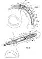
- Figure 1 is a side view, partly in section, of one embodiment of the penile erectile system of the present invention in a non-pressurized condition surgically implanted in a male;
- Figure 2 is a side view similar to Figure 1, except that the system is pressurized;
- Figure 3 is a cross sectional view taken along the line 3-3 in Figure 1;
- Figure 4 is a cross sectional view taken along the line 4-4 in Figure 2;
- Figure 5 is a top plan view, partly in section of another embodiment of the system of the present invention; and
- Figure 6 is a cross sectional view taken along line 6-6 in Figure 5.
- The preferred embodiment of the penile
erectile system 10, which is seen in Figures 1 to 4, comprises a pair of elongate implants 11, 11'. The two implants 11, 11' are identical, therefore only one will be described in detail. - As seen in Figure 1, the implant 11 has a short,
proximal stem 12 of relatively stiff material which is implanted in the root end of a corpus cavernosum to support and anchor the implant, an intermediatecylindrical portion 13, and a conicaldistal tip 14. Thetubular portion 13 and thetip 14 which are soft and flexible are implanted in the portion of the corpus cavernosum in the pendulous penis. As seen in Figures 2 and 4, each of the implants 11, 11' is positioned in a separate corpus cavernosum of the penis. - The intermediate
cylindrical portion 13 of the implant 11 includes a pair of concentriccylindrical sleeves stem 12 and to thetip 14 to form a pair ofcoaxial chambers sleeve 15 which forms the wall of theinner chamber 17 is of a silicone coated mesh orwoven fabric 19 which is inelastic and as a result thechamber 17 is non-distensible. Thesleeve 15 also serves as the inner wall of the annularouter chamber 18. Thesleeve 16 which is spaced outwardly from thesleeve 15 may be of a distensible material such as nonreinforced silicone rubber and it forms the outer wall of theannular chamber 18. The fluid tight seals between thesleeves stem 12 andtip 14 may be made with a suitable silicone adhesive or by other conventional means. - As seen in Figures 1 and 3, even in a non-pressurized state the
chambers biocompatible fluid 20 which may be saline or a free flowing silicone gel. When thenon-distensible chamber 17 is not pressurized, the soft, flexible, intermediatetubular portion 13 of the implant 11 permits the penis to assume a substantially normal, flaccid position as seen in Figure 1. However, when thechamber 17 is completely filled and pressurized, the penis assumes an erect position as seen in Figure 2. - As seen most clearly in Figure 1, a
passage 21 connects thechambers passage 21 is shaped to form a pump valve consisting of an enlargedintermediate bulbar portion 22 and a pair ofthroats chambers - As seen only in Figure 1, when the
system 10 is in its normal non-pressurized state theentire passage 21 including thebulbar portion 22 of the pump valve is filled withhydraulic fluid 20 and both of thethroats chambers fluid 20. Thesystem 10 is pressurized by repeatedly squeezing thebulbar portion 22 to pumphydraulic fluid 20 out of theouter chamber 18 throughthroat 23,bulbar portion 22 andthroat 24 to fill non-distensibleinner chamber 17 withfluid 20 under pressure. When thechamber 17 is sufficiently pressurized and rigid thebulbar portion 22 is released whereby thethroat 23 is closed by pressure exerted by thehydraulic fluid 20 upon a resilientinner portion 25 of theend wall 26 of thechamber 17 adjacent thethroat 23. As a result, thechamber 17 remains completely filled, pressurized and rigid, as seen in Figure 2, until the wall portion is manually deformed by squeezing to open thethroat 23 and allowfluid 20 to flow back into thechamber 18 and thesystem 10 to resume a non-pressurized state. - The pressurizing of the
non-distensible chamber 17 is facilitated by manually squeezing theouter chamber 18 to milk the fluid which is in that chamber through thethroat 23,bulbar portion 22 andthroat 24 into thechamber 18. - A variety of pump valves other than that shown in the drawing can be used. Preferably, the pump valve is of the type which opens when it is squeezed, automatically closes when the squeezing stops and can be manipulated from the outside. If desired, separate pumps and valves can be used in place of the combined pump valve.
- A second embodiment of the system of the present invention is seen in Figures 5 and 6. The
system 110 seen therein is contained in asingle implant 111 which has a pair ofstems 112, 112' at the distal end, a pair oftips 114, 114' at the proximal end, and a common trunk orintermediate portion 113 which containsconcentric chambers chambers passage 121 having a . bulbar orpump portion 122 andthroats passage 121. - The system of the second embodiment is implanted in corpora cavernosum of the penis after removing the tissue separating the individual corpus.
- The term "substantially filled" as used herein to describe the fluid content of a chamber means that a chamber contains about 60% to about 95% or more of its capacity of a non-compressible fluid such as water, saline or a 'free flowing gel. The actual content of fluid can vary; however, the distal portion of the implant when "substantially filled" should be still sufficiently flexible so that the penis can assume a normal flaccid position.
- All the parts and components of the prosthesis are preferably made of or covered with medical grade silicone rubber which is nonreactive, non-toxic and well tolerated by the adjacent organic tissues. Silicone rubber is preferred because it is quite resistant to wear and remains functional for long periods of time. However, other suitable materials possessing desirable properties may also be employed.
- The non-distensible inner chamber (17, 17' or 117) must provide when pressurized rigidity sufficient to maintain the penis in an erectile position. Therefore, it must be of sufficient volume and size to perform this function either alone or in combination with another implant. In contrast, the
outer chamber 18 serves primarily as a reservoir of pressurizing fluid for inner chamber and is sized accordingly. The exact dimensions of the chambers are not critical as long as they are adequate to provide the desired function of the chamber. - The
sleeve 15 which forms the wall of the "non-distensible"chamber 17 is preferably made of a dacron (Trade Mark) mesh or fabric covered with silicone material so that it will not stretch when filled with fluid and pressurized. Thesleeve 16 may be non-distensible or may be made of unreinforced silicone rubber. The diameters of thesleeves - The proximal stems of the implants preferably have a Shore A hardness of about 70, the distal tips a Shore A hardness of about 20, and each of the materials have sufficient tensile strength for its intended use. In the preferred embodiments of the drawings, the tips are tapered and filled with a self-sealing silicone elastomer E to allow fluid to be added to or removed from the chambers with a fine needle and syringe.
- The preferred method of implantation of the erectile system is through an incision made in the penis. After appropriate incision, the corpus cavernosum is dialted distally proximally to accept the implant. The appropriate anatomical measurements are made to insure that the proximal stem of the implant or implants will be positioned at the base of the penis below the pelvic bone. An implant or implants having an appropriately sized intermediate section and distal tip is inserted into the corpus cavernosum of the penis. The distal tip is positioned in the tunica end of the corpus cavernosum. The proximal stem of the implant then is anchored in the root end of the corpus cavernosum.
- The identical procedure is performed on the other side of the penis to complete the surgical procedure. The proximal stems of the two implants preferably will diverge laterally to accommodate the anatomy and provide lateral stability to the penis. When the embodiment utilizing a single implant is employed, the tissue separating the corpora cavernosum is removed before positioning the implant. The incision is then closed.
- It is to be understood that the foregoing description has been for purposes of illustration and that a number of modifications and changes may be made without departing from the scope of the present invention. For example, although the implants described have solid stems for anchoring the implants, the stems could be hollow, if desired. In addition, although implants have been described and illustrated in which the outer chamber which serves as the reservoir is coaxial relative to the inner chamber it will be appreciated that the reservoir role could be provided by one or more radially disposed smaller individual outer chambers if desired.
Claims (8)
1. A penile implant having an elongate cylindrical body (11) with an anchoring stem (12) at the proximal end; a tip (14) at the distal end; characterised by an inner chamber (17) and an outer chamber (18) located intermediate the length of said body between the stem (12) and the tip (14), the inner chamber (17) being non-distensible so that when pressurized and filled with fluid it becomes rigid and the outer chamber (18) having a volume sufficient to accommodate enough transferable fluid to completely fill and pressurize the inner chamber (17); a passage (21) providing communication between the inner and outer chambers (17, 18) and means (25) for retaining fluid (20) transferred from the outer chamber (18) into the inner chamber (17) to keep it pressurized and rigid.
2. An implant as claimed in claim 1, wherein the chambers (17, 18) are coaxial.
3. An implant as claimed in claim 1 or claim 2, wherein there is a plurality of outer chambers (18).
4. The implant as claimed in any one of the preceding claims, which includes a pump (22) for transferring fluid from the outer chamber or chambers into the inner chamber.
5. The implant as claimed in claim 4, in which a combined pump valve (22-25) is used to transfer fluid.
6. The implant as claimed in any one of the preceding claims, in which when the inner chamber is not pressurized, both chambers (17, 18) are filled from about 60% to about 95% with hydraulic fluid (20).
7. The implant as claimed in any one of the preceding claims, in which the implant has a pair of stems (117), a pair of tips (114) and a common intermediate trunk (110) which includes the inner and outer chambers (117, 118).
8. A penis erectile system including one or more of the implants of any one of the preceding claims.
Applications Claiming Priority (2)
| Application Number | Priority Date | Filing Date | Title |
|---|---|---|---|
| US06/202,591US4353360A (en) | 1980-10-31 | 1980-10-31 | Penile erectile system |
| US202591 | 1980-10-31 |
Publications (2)
| Publication Number | Publication Date |
|---|---|
| EP0051420A1 EP0051420A1 (en) | 1982-05-12 |
| EP0051420B1true EP0051420B1 (en) | 1984-06-27 |
Family
ID=22750520
Family Applications (1)
| Application Number | Title | Priority Date | Filing Date |
|---|---|---|---|
| EP81305054AExpiredEP0051420B1 (en) | 1980-10-31 | 1981-10-27 | Penile erectile system |
Country Status (5)
| Country | Link |
|---|---|
| US (1) | US4353360A (en) |
| EP (1) | EP0051420B1 (en) |
| JP (1) | JPS57164048A (en) |
| CA (1) | CA1176803A (en) |
| DE (1) | DE3164460D1 (en) |
Cited By (4)
| Publication number | Priority date | Publication date | Assignee | Title |
|---|---|---|---|---|
| US7946975B2 (en) | 2005-04-08 | 2011-05-24 | Ams Research Corporation | Fluid reservoir for penile implant devices |
| US8114011B2 (en) | 2007-10-23 | 2012-02-14 | Ams Research Corporation | Corrugated inflatable penile prosthesis cylinder |
| US8123674B2 (en) | 2007-11-12 | 2012-02-28 | Ams Research Corporation | Corrugated expansion-constraining sleeve for an inflatable penile prosthesis cylinder |
| US8276591B2 (en) | 2000-12-27 | 2012-10-02 | Ams Research Corporation | Diaphragm based spontaneous inflation inhibitor in a pump for an inflatable prosthesis |
Families Citing this family (75)
| Publication number | Priority date | Publication date | Assignee | Title |
|---|---|---|---|---|
| US4682589A (en)* | 1980-05-15 | 1987-07-28 | Medical Engineering Corporation | Penile prosthesis |
| US4622958A (en)* | 1984-12-12 | 1986-11-18 | Medical Engineering Corporation | Penile implant with accumulator |
| US4532920A (en)* | 1980-05-15 | 1985-08-06 | Medical Engineering Corporation | Penile implant |
| US4407278A (en)* | 1981-05-15 | 1983-10-04 | American Medical Systems, Inc. | Penile prosthesis with improved fluid control |
| US4550719A (en)* | 1981-08-04 | 1985-11-05 | Medical Engineering Corporation | Implantable penile erectile system |
| US4399811A (en)* | 1981-08-04 | 1983-08-23 | Medical Engineering Corporation | Implantable penile erectile system |
| WO1984003038A1 (en)* | 1983-02-14 | 1984-08-16 | Robert E Trick | Implantable penile erectile system |
| US4457335A (en)* | 1981-09-24 | 1984-07-03 | Medical Engineering Corporation | Penile erectile system |
| US4574792A (en)* | 1981-09-24 | 1986-03-11 | Medical Engineering Corporation | Penile erectile system |
| US4399812A (en)* | 1981-12-31 | 1983-08-23 | Whitehead Edgar D | Penile prosthetic device |
| US4564006A (en)* | 1982-06-15 | 1986-01-14 | Pomeranz Mark L | Reclosable condom |
| US4432357A (en)* | 1982-06-15 | 1984-02-21 | Pomeranz Mark L | Condom with rheopexic filled deformable chamber |
| US4625716A (en)* | 1982-06-15 | 1986-12-02 | Pomeranz Mark L | Penile prosthesis with rheopexic material enclosed in a chamber |
| US4559931A (en)* | 1983-03-21 | 1985-12-24 | Fischell Robert | Manually actuated fully implantable penile erection device |
| US4566446A (en)* | 1983-04-08 | 1986-01-28 | Mentor Corporation | Penile prosthesis device |
| US4522198A (en)* | 1983-04-18 | 1985-06-11 | Dacomed Corporation | Penile prosthesis |
| US4517967A (en)* | 1983-04-18 | 1985-05-21 | Dacomed Corporation | Penile prosthesis |
| US4596242A (en)* | 1983-08-26 | 1986-06-24 | Fischell Robert | Method and apparatus for achieving penile erection in a human male |
| US4558693A (en)* | 1983-08-29 | 1985-12-17 | Harvey Lash | Penile implant |
| US4550720A (en)* | 1983-11-15 | 1985-11-05 | Medical Engineering Corporation | Capacitance device for medical implant |
| US4572168A (en)* | 1983-12-20 | 1986-02-25 | Fischell Robert | Fully implantable vapor pressure actuated penile erection device and method |
| US4653485A (en)* | 1984-07-23 | 1987-03-31 | Fishell Robert E | Penile erection device stiffener cylinder and implantation method |
| DE3529613A1 (en)* | 1984-08-20 | 1986-02-27 | Robert Ellentuch Silver Spring Fischell, Md. | REINFORCEMENT CYLINDER FOR AN INFLATABLE PENIS READING DEVICE |
| US4628912A (en)* | 1984-08-20 | 1986-12-16 | Fischell Robert | Adjustable root and tip extenders for the stiffener cylinder of a penile erection device |
| US4730607A (en)* | 1984-08-20 | 1988-03-15 | Fischell Robert | Stiffener cylinder for an inflatable penile erection device |
| US4594997A (en)* | 1984-11-13 | 1986-06-17 | Hakky Said I | Self actuated penile implant |
| US4602621A (en)* | 1984-12-18 | 1986-07-29 | Hakky Said I | Manually actuated, self contained penile implant |
| US4590927A (en)* | 1985-02-25 | 1986-05-27 | American Medical Systems, Inc. | Unitary, inflatable penile prosthesis system |
| US4651721A (en)* | 1985-04-10 | 1987-03-24 | American Medical Systems, Inc. | Penile prosthesis system |
| US4726360A (en)* | 1986-07-17 | 1988-02-23 | Medical Engineering Corporation | Penile prosthesis |
| US4917110A (en)* | 1986-07-17 | 1990-04-17 | Medical Engineering Corporation | Penile prosthesis |
| US4711231A (en)* | 1986-11-03 | 1987-12-08 | Aaron N. Finegold | Implantable prosthesis system |
| US4881531A (en)* | 1986-11-21 | 1989-11-21 | Dacomed Corporation | Position stable segmented column penile prosthesis |
| US4823779A (en)* | 1987-05-15 | 1989-04-25 | Medical Engineering Corporation | Penile implant with compensator |
| US4898158A (en)* | 1987-05-15 | 1990-02-06 | Medical Engineering Corporation | Penile implant with improved pressure relief valve |
| US4773403A (en)* | 1987-08-17 | 1988-09-27 | Medical Engineering Corporation | Penile prosthesis |
| US4881530A (en)* | 1988-01-19 | 1989-11-21 | Medical Engineering Corporation | Penile prosthesis |
| US4895139A (en)* | 1988-08-29 | 1990-01-23 | American Medical Systems, Inc. | Inflatable penile prosthesis with bend release valve |
| US4995380A (en)* | 1989-11-07 | 1991-02-26 | Medical Engineering Corporation | Penile prosthesis |
| US5010882A (en)* | 1989-11-13 | 1991-04-30 | American Medical Systems, Inc. | Implantable penile prosthesis |
| US5067485A (en)* | 1990-05-14 | 1991-11-26 | Mentor Corporation | Corpus cavernosum implant device |
| US5141509B1 (en)* | 1991-08-06 | 1996-01-23 | American Med Syst | Penile prosthesis having means for preventing spontaneous inflation |
| US5263981A (en)* | 1992-04-24 | 1993-11-23 | American Medical Systems, Inc. | Implantable penile prosthesis |
| US5851176A (en) | 1996-07-29 | 1998-12-22 | Mentor Corporation | Pressure-responsive lockout valve and method of use |
| CN101351173B (en)* | 2005-12-19 | 2011-01-26 | 康乐保公司 | Pump with one-touch release |
| US8052593B2 (en) | 2006-10-24 | 2011-11-08 | Ams Research Corporation | Implantable malleable penile prosthetic device |
| US8109870B2 (en) | 2006-11-10 | 2012-02-07 | Ams Research Corporation | Inflatable penile prosthesis bypass valve noise reduction |
| US8911350B2 (en) | 2007-10-23 | 2014-12-16 | Ams Research Corporation | Malleable prosthesis with enhanced concealability |
| US7918782B2 (en)* | 2007-11-15 | 2011-04-05 | Ams Research Corporation | Prosthesis with bladder that adjusts girth |
| US10070955B2 (en)* | 2007-11-15 | 2018-09-11 | Boston Scientific Scimed, Inc. | Prosthesis with bendable central region |
| US8052594B2 (en)* | 2007-11-20 | 2011-11-08 | Ams Research Corporation | Prosthetic device with protrusions for girth |
| US7988568B2 (en)* | 2008-01-17 | 2011-08-02 | Nike, Inc. | Golf clubs and golf club heads with adjustable center of gravity and moment of inertia characteristics |
| WO2009124554A1 (en)* | 2008-04-07 | 2009-10-15 | Coloplast A/S | Implantable fluid devices |
| US7922649B2 (en)* | 2008-08-08 | 2011-04-12 | Walch John R | Unitized penile erection system and tissue expander |
| US8545391B2 (en) | 2008-12-23 | 2013-10-01 | Ams Research Corporation | Penile prosthesis implantation device |
| DK200970206A (en)* | 2009-11-16 | 2011-05-17 | Coloplast As | Penile prosthetic with anti-autoinflation mechanism |
| US8545393B2 (en)* | 2010-02-04 | 2013-10-01 | Coloplast A/S | Inflatable penile implant |
| US8016746B2 (en)* | 2010-02-03 | 2011-09-13 | Coloplast A/S | Inflatable penile implant |
| US8241203B2 (en)* | 2010-02-12 | 2012-08-14 | Fogarty Terence M | Inflatable penile prosthesis with spool valve |
| US8636645B2 (en)* | 2010-07-16 | 2014-01-28 | Coloplast A/S | Method of treating erectile dysfunction with peristaltically inflatable penile prosthetic |
| US9474610B2 (en) | 2010-12-21 | 2016-10-25 | Boston Scientific Scimed, Inc. | Adjustable length rear tip extender for penile prosthesis |
| US8257246B1 (en) | 2011-04-19 | 2012-09-04 | Coloplast A/S | Penile prosthetic system and pump having inlet valve with high velocity closure mechanism |
| US9084678B2 (en) | 2012-01-20 | 2015-07-21 | Ams Research Corporation | Automated implantable penile prosthesis pump system |
| US9089426B2 (en) | 2012-03-21 | 2015-07-28 | Ams Research Corporation | Automated implantable penile prosthesis pump system |
| EP3508174A1 (en)* | 2012-09-27 | 2019-07-10 | Boston Scientific Scimed, Inc. | Implantable penile prosthesis |
| US9554937B2 (en) | 2014-06-16 | 2017-01-31 | Coloplast A/S | Penile prosthetic pump having an inlet valve with a lockout flange |
| US9649217B2 (en) | 2014-07-08 | 2017-05-16 | Coloplast A/S | Implantable penile prosthetic lockout valve assembly |
| US9486231B2 (en) | 2014-08-08 | 2016-11-08 | Coloplast A/S | Tool with a clasp useful for implanting a penile prosthetic cylinder |
| US9480566B2 (en) | 2014-08-08 | 2016-11-01 | Coloplast A/S | Tool with a groove useful for implanting a penile prosthetic cylinder |
| US9724197B2 (en) | 2014-09-10 | 2017-08-08 | Coloplast A/S | Tool with a suction feature useful for implanting a penile prosthetic cylinder |
| US9642707B2 (en) | 2014-09-29 | 2017-05-09 | Coloplast A/S | Tool with a pincher useful for implanting an inflatable penile cylinder |
| US9987136B2 (en) | 2016-09-09 | 2018-06-05 | Coloplast A/S | Penile prosthetic pump with an inflation assembly including a rotary valve |
| US10729546B2 (en) | 2017-02-02 | 2020-08-04 | Coloplast A/S | Inflatable penile prosthetic system |
| US11337815B2 (en)* | 2019-05-08 | 2022-05-24 | Boston Scientific Scimed, Inc. | Inflatable member with core members |
| US11819412B2 (en) | 2020-02-04 | 2023-11-21 | Coloplast A/S | Penile prostheses for treatment of erectile dysfunction |
Citations (4)
| Publication number | Priority date | Publication date | Assignee | Title |
|---|---|---|---|---|
| US3853122A (en)* | 1973-10-12 | 1974-12-10 | B Strauch | Method and device for achieving a penile erection |
| US3954102A (en)* | 1974-07-19 | 1976-05-04 | American Medical Systems, Inc. | Penile erection system and methods of implanting and using same |
| US4009711A (en)* | 1976-03-17 | 1977-03-01 | Uson Aurelio C | Penile prosthesis for the management of erectile impotence |
| US4066073A (en)* | 1976-10-04 | 1978-01-03 | Medical Engineering Corporation | Composite rod penile implant |
Family Cites Families (2)
| Publication number | Priority date | Publication date | Assignee | Title |
|---|---|---|---|---|
| US4201202A (en)* | 1978-09-25 | 1980-05-06 | Medical Engineering Corp. | Penile implant |
| US4267829A (en)* | 1979-04-11 | 1981-05-19 | American Medical Systems, Inc. | Penile prosthesis |
- 1980
- 1980-10-31USUS06/202,591patent/US4353360A/ennot_activeExpired - Lifetime
- 1981
- 1981-10-02CACA000387183Apatent/CA1176803A/ennot_activeExpired
- 1981-10-27EPEP81305054Apatent/EP0051420B1/ennot_activeExpired
- 1981-10-27DEDE8181305054Tpatent/DE3164460D1/ennot_activeExpired
- 1981-10-31JPJP56175562Apatent/JPS57164048A/enactiveGranted
Patent Citations (4)
| Publication number | Priority date | Publication date | Assignee | Title |
|---|---|---|---|---|
| US3853122A (en)* | 1973-10-12 | 1974-12-10 | B Strauch | Method and device for achieving a penile erection |
| US3954102A (en)* | 1974-07-19 | 1976-05-04 | American Medical Systems, Inc. | Penile erection system and methods of implanting and using same |
| US4009711A (en)* | 1976-03-17 | 1977-03-01 | Uson Aurelio C | Penile prosthesis for the management of erectile impotence |
| US4066073A (en)* | 1976-10-04 | 1978-01-03 | Medical Engineering Corporation | Composite rod penile implant |
Cited By (4)
| Publication number | Priority date | Publication date | Assignee | Title |
|---|---|---|---|---|
| US8276591B2 (en) | 2000-12-27 | 2012-10-02 | Ams Research Corporation | Diaphragm based spontaneous inflation inhibitor in a pump for an inflatable prosthesis |
| US7946975B2 (en) | 2005-04-08 | 2011-05-24 | Ams Research Corporation | Fluid reservoir for penile implant devices |
| US8114011B2 (en) | 2007-10-23 | 2012-02-14 | Ams Research Corporation | Corrugated inflatable penile prosthesis cylinder |
| US8123674B2 (en) | 2007-11-12 | 2012-02-28 | Ams Research Corporation | Corrugated expansion-constraining sleeve for an inflatable penile prosthesis cylinder |
Also Published As
| Publication number | Publication date |
|---|---|
| CA1176803A (en) | 1984-10-30 |
| JPS57164048A (en) | 1982-10-08 |
| DE3164460D1 (en) | 1984-08-02 |
| US4353360A (en) | 1982-10-12 |
| EP0051420A1 (en) | 1982-05-12 |
| JPS6160700B2 (en) | 1986-12-22 |
Similar Documents
| Publication | Publication Date | Title |
|---|---|---|
| EP0051420B1 (en) | Penile erectile system | |
| US4399811A (en) | Implantable penile erectile system | |
| US4574792A (en) | Penile erectile system | |
| US4726360A (en) | Penile prosthesis | |
| US4364379A (en) | Penile erectile system | |
| CA1298440C (en) | Penile prosthesis | |
| US4369771A (en) | Penile erectile system | |
| US4201202A (en) | Penile implant | |
| US4318396A (en) | Penile prosthesis | |
| US4360010A (en) | Penile prosthesis | |
| US4523584A (en) | Penile erectile system | |
| US4602625A (en) | Penile erectile system | |
| US4881530A (en) | Penile prosthesis | |
| US4342308A (en) | Penile erectile system | |
| US4550720A (en) | Capacitance device for medical implant | |
| US4550719A (en) | Implantable penile erectile system | |
| US4378792A (en) | Penile prosthesis | |
| EP0120012B1 (en) | Penile erectile system | |
| US4682589A (en) | Penile prosthesis | |
| US4611584A (en) | Expandable penile implant | |
| US4791917A (en) | Penile prosthesis | |
| US4411261A (en) | Semi-rigid penile implant | |
| US4532920A (en) | Penile implant | |
| US4995380A (en) | Penile prosthesis | |
| WO1984003038A1 (en) | Implantable penile erectile system |
Legal Events
| Date | Code | Title | Description |
|---|---|---|---|
| PUAI | Public reference made under article 153(3) epc to a published international application that has entered the european phase | Free format text:ORIGINAL CODE: 0009012 | |
| AK | Designated contracting states | Designated state(s):DE FR GB IT | |
| 17P | Request for examination filed | Effective date:19820410 | |
| ITF | It: translation for a ep patent filed | ||
| GRAA | (expected) grant | Free format text:ORIGINAL CODE: 0009210 | |
| AK | Designated contracting states | Designated state(s):DE FR GB IT | |
| REF | Corresponds to: | Ref document number:3164460 Country of ref document:DE Date of ref document:19840802 | |
| ET | Fr: translation filed | ||
| PLBE | No opposition filed within time limit | Free format text:ORIGINAL CODE: 0009261 | |
| STAA | Information on the status of an ep patent application or granted ep patent | Free format text:STATUS: NO OPPOSITION FILED WITHIN TIME LIMIT | |
| 26N | No opposition filed | ||
| ITTA | It: last paid annual fee | ||
| PGFP | Annual fee paid to national office [announced via postgrant information from national office to epo] | Ref country code:FR Payment date:20001010 Year of fee payment:20 | |
| PGFP | Annual fee paid to national office [announced via postgrant information from national office to epo] | Ref country code:DE Payment date:20001023 Year of fee payment:20 | |
| PGFP | Annual fee paid to national office [announced via postgrant information from national office to epo] | Ref country code:GB Payment date:20001025 Year of fee payment:20 | |
| PG25 | Lapsed in a contracting state [announced via postgrant information from national office to epo] | Ref country code:GB Free format text:LAPSE BECAUSE OF EXPIRATION OF PROTECTION Effective date:20011026 | |
| REG | Reference to a national code | Ref country code:GB Ref legal event code:PE20 Effective date:20011026 |