EP0051306B1 - Control for automobile air conditioning system - Google Patents
Control for automobile air conditioning systemDownload PDFInfo
- Publication number
- EP0051306B1 EP0051306B1EP81109410AEP81109410AEP0051306B1EP 0051306 B1EP0051306 B1EP 0051306B1EP 81109410 AEP81109410 AEP 81109410AEP 81109410 AEP81109410 AEP 81109410AEP 0051306 B1EP0051306 B1EP 0051306B1
- Authority
- EP
- European Patent Office
- Prior art keywords
- function
- temperature
- blower fan
- fan speed
- value
- Prior art date
- Legal status (The legal status is an assumption and is not a legal conclusion. Google has not performed a legal analysis and makes no representation as to the accuracy of the status listed.)
- Expired
Links
- 238000004378air conditioningMethods0.000titledescription9
- 230000006870functionEffects0.000claimsdescription33
- 230000001105regulatory effectEffects0.000claimsdescription6
- 230000001276controlling effectEffects0.000claimsdescription2
- 238000012886linear functionMethods0.000claims1
- 238000010438heat treatmentMethods0.000description6
- 238000001816coolingMethods0.000description5
- 230000007423decreaseEffects0.000description3
- 238000010586diagramMethods0.000description3
- 238000004891communicationMethods0.000description1
- 238000011217control strategyMethods0.000description1
- 230000003247decreasing effectEffects0.000description1
- 238000011161developmentMethods0.000description1
- 230000018109developmental processEffects0.000description1
- 239000012530fluidSubstances0.000description1
- 238000000034methodMethods0.000description1
Images


Classifications
- B—PERFORMING OPERATIONS; TRANSPORTING
- B60—VEHICLES IN GENERAL
- B60H—ARRANGEMENTS OF HEATING, COOLING, VENTILATING OR OTHER AIR-TREATING DEVICES SPECIALLY ADAPTED FOR PASSENGER OR GOODS SPACES OF VEHICLES
- B60H1/00—Heating, cooling or ventilating [HVAC] devices
- B60H1/00642—Control systems or circuits; Control members or indication devices for heating, cooling or ventilating devices
- B60H1/00814—Control systems or circuits characterised by their output, for controlling particular components of the heating, cooling or ventilating installation
- B60H1/00821—Control systems or circuits characterised by their output, for controlling particular components of the heating, cooling or ventilating installation the components being ventilating, air admitting or air distributing devices
- B60H1/00828—Ventilators, e.g. speed control
- G—PHYSICS
- G05—CONTROLLING; REGULATING
- G05D—SYSTEMS FOR CONTROLLING OR REGULATING NON-ELECTRIC VARIABLES
- G05D23/00—Control of temperature
- G05D23/19—Control of temperature characterised by the use of electric means
- G05D23/1917—Control of temperature characterised by the use of electric means using digital means
- G—PHYSICS
- G05—CONTROLLING; REGULATING
- G05D—SYSTEMS FOR CONTROLLING OR REGULATING NON-ELECTRIC VARIABLES
- G05D23/00—Control of temperature
- G05D23/19—Control of temperature characterised by the use of electric means
- G05D23/20—Control of temperature characterised by the use of electric means with sensing elements having variation of electric or magnetic properties with change of temperature
- Y—GENERAL TAGGING OF NEW TECHNOLOGICAL DEVELOPMENTS; GENERAL TAGGING OF CROSS-SECTIONAL TECHNOLOGIES SPANNING OVER SEVERAL SECTIONS OF THE IPC; TECHNICAL SUBJECTS COVERED BY FORMER USPC CROSS-REFERENCE ART COLLECTIONS [XRACs] AND DIGESTS
- Y10—TECHNICAL SUBJECTS COVERED BY FORMER USPC
- Y10S—TECHNICAL SUBJECTS COVERED BY FORMER USPC CROSS-REFERENCE ART COLLECTIONS [XRACs] AND DIGESTS
- Y10S236/00—Automatic temperature and humidity regulation
- Y10S236/09—Fan control
Definitions
- the inventionrelates to a control system for an automobile air conditioner, comprising: an air conditioner comprising a blower fan driven by a motor and air temperature regulating means, a reference temperature supplier for supplying a predetermined reference temperature, a temperature sensor for sensing the temperature of the passenger compartment of the automobile, blower fan speed control means connected with said reference temperature supplier and said temperature sensor for controlling the speed of the blower fan by calculating the temperature difference between the reference temperature and the sensed temperature and determining in accordance with the calculated temperature difference, the value of a first function which increases as said difference increases and determines the speed of the blower fan and produces a control signal indicative of the determined blower fan speed and blower fan speed regulating means connected with said control means for regulating the blower fan speed under the command of said control means.
- EP-A-31518discloses an air conditioning system for vehicles in which the control means comprises a microcomputer having a read-only memory storing the first function having a characteristic relationship between the calculated temperature difference and air flow values corresponding to a command signal for a motor drive circuit driving the motor of the blower fan. Therefore, this prior art system suffers from the same drawback as indicated above.
- said taskis solved in that said blower fan speed control means being arranged to calculate the absolute value of the temperature difference and to determine the value of a second function which increases as said absolute value increases and is always greater than the value of said first function, said control means determining the fan speed as being equal to the determined value of said second function if the current fan speed is greater than the determined value of said second function and as being equal to the determined value of said first function if the current fan speed is smaller than the determined value of first function while maintaining the current fan speed unchanged if the current fan speed is neither greater than the determined value of said second function nor smaller than the determined value of said first function.
- the blower fan speedis not controlled along a sole line or function.
- the control systemdoes not increase the blower fan speed directly along the second function. Instead, the control system maintains the blower fan speed constant along a horizontal line from the point lying on the second function to a point lying on the first function.
- the blower fan speedis maintained constant.
- the present inventionby permitting operation along horizontal lines in the region between the two functions, permits maintaining the blower fan speed at constant levels independently of minor temperature fluctuations.
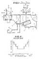
- FIG. 1air is drawn in through an air inlet 3 by a blower fan 2 driven by a motor 1, and cooled by a cooling unit 4. After being cooled, a part of the air is introduced into a heating unit 6, and an air mixing door 5 proportions the amount of air permitted to pass through the heating unit 6 in accordance with its opening degree. Then, in order to obtain air of a desired temperature, the heated part of the incoming air is mixed again with the remaining part of the incoming air which does not pass through the heating unit. The mixed air is then blown off through a plurality of air outlets 7, 8 and 9 into the passenger compartment.
- a reference numeral 10denotes a compressor of the cooling unit 4.
- the air mixing door 5is actuated by an actuator 11, which is controlled by a solenoid valve 14 for introducing the intake vacuum into the actuator 11 and a solenoid valve 15 for making fluid communication between the actuator 11 and the atmosphere.
- a sensor 12for sensing the opening degree of the air mixing door 5, and a slide switch 13 linked with the air mixing door 5.
- An air inlet door 16is provided to select air coming into the air conditioning system. When the air intake door 16 takes the position shown by a solid line in Fig. 1, fresh outside air is allowed to enter the system and refreshes the air in the passenger compartment. When on the other hand, the air intake door 16 is at the position shown by a broken line, the air inside the compartment is recirculated into the system thereby to provide efficient cooling or heating.
- the flow rate of hot or cool airis generally controlled depending on the opening degree of the air mixing door, as shown in Fig. 2 for example.
- the quantity of discharged hot or cool airis changed in accordance with the opening degree of the air mixing door, and becomes maximum both in a full hot mode where the air mixing door is fully open and the maximum heating power is developed, and in a full cool mode where the air mixing door is fully closed and the maximum cooling power is developed.
- the air conditioning system of Fig. 2When the ambient temperature is high or low, the air conditioning system of Fig. 2, however, must often continue to run in the full hot mode or the full cool mode for a relatively long time at a starting period in order to supply enough heat matching a large temperature gap between a target temperature and an actual temperature. During that time, the blower fan, too, continues to run at the full speed, and therefore, the fan noise becomes very troublesome.
- the air temperature and the air flow rateare changed together in accordance with the position of the air mixing door, and on the other hand, the air conditioning power, that is heat supply, is determined by a product of the air temperature and the air flow rate. Therefore, although this system can provide sufficient heating or cooling power at or near the full closed state or the full open state of the air mixing door, a slight position change of the air mixing door brings about a considerable decrease of the air conditioning power of the system.
- a reference room temperature supplier 20generates a reference room temperature signal To, and a room temperature sensor 21 senses the temperature of the passenger compartment room and generates a room temperature signal Tr indicative of a sensed temperature. Both of the signals To and Tr are sent to an analogue to digital converter 22, which changes the input analogue signals into corresponding digital signals.
- An operational unit 23receives the output signals of the analogue to digital converter 22, performs an operation in accordance with a prescribed rule (which will be explained hereinafter), and obtains a motor voltage Vm of the blower fan motor 1.
- a motor driving circuit 24drives the blower fan motor 1 in accordance with the motor voltage signal Vm sent from the operational unit 23.
- the operational unit 23calculates the absolute value (Delta T) of the temperature difference between To and Tr at a step 32, and at a next step 33, obtains the motor voltage Vm from the absolute value of the temperature difference in accordance with a rule shown by the flowchart of Fig. 5.
- the characteristic of the blower fan motor voltage Vmis predetermined as a function of the absolute value (Delta T) of the temperature difference between To and Tr.
- Vmis determined according to a first function or lower characteristic curve V1 (a solid line) in the case of an increase of Delta T, and according to a second function or an upper characteristic curve V2 (a broken line) in the case of a decrease of Delta T.
- step 51a voltage control command signal is delivered with the value of Vm decided at the step 45 or 46.
- Vma voltage control command signal
- the programgoes from the step 43 to a step 47, where it is decided whether Vm is equal to or greater than the lower value V1. If it is, the program goes directly to the step 51, and if it is not, it is further decided at a step 48 whether V1 is equal to or smaller than LOW which is a lower limit value of Vm. If V1 is greater than LOW, Vm is set at V1 at a step 49, and if V1 is equal to or smaller than LOW, Vm is set at LOW at a step 50. Then, the program goes from the step 49 or 50 to the step 51.
Landscapes
- Physics & Mathematics (AREA)
- Engineering & Computer Science (AREA)
- General Physics & Mathematics (AREA)
- Automation & Control Theory (AREA)
- Thermal Sciences (AREA)
- Mechanical Engineering (AREA)
- Air-Conditioning For Vehicles (AREA)
- Air Conditioning Control Device (AREA)
Description
- The invention relates to a control system for an automobile air conditioner, comprising: an air conditioner comprising a blower fan driven by a motor and air temperature regulating means, a reference temperature supplier for supplying a predetermined reference temperature, a temperature sensor for sensing the temperature of the passenger compartment of the automobile, blower fan speed control means connected with said reference temperature supplier and said temperature sensor for controlling the speed of the blower fan by calculating the temperature difference between the reference temperature and the sensed temperature and determining in accordance with the calculated temperature difference, the value of a first function which increases as said difference increases and determines the speed of the blower fan and produces a control signal indicative of the determined blower fan speed and blower fan speed regulating means connected with said control means for regulating the blower fan speed under the command of said control means.
- Such a system is disclosed in US-A-3 990 505. In such a system, a reference temperature and a sensed temperature are compared with one another. The output signal of the comparator drives an electric motor the output shaft of which rotates cams at a low speed through a reduction gear arrangement. A cam follower associated to the cams operates a rheostat which in turn controls the motor for the blower fan. Said prior system suffers from the drawback that the speed of the blower fan is varied also in accordance with only small temperature differences, that means, small temperature variations of the sensed temperature. Such a blower fan speed fluctuations provide a very irritating noise for the driver and passengers within the automobile compartment.
- EP-A-31518 discloses an air conditioning system for vehicles in which the control means comprises a microcomputer having a read-only memory storing the first function having a characteristic relationship between the calculated temperature difference and air flow values corresponding to a command signal for a motor drive circuit driving the motor of the blower fan. Therefore, this prior art system suffers from the same drawback as indicated above.
- It is the task of the invention to improve a control system as indicated in the prior art part of claim 1 such, that blower fan noise due to blower fan speed fluctuations is less troublesome.
- In a control system as indicated in the prior art part of claim 1, said task is solved in that said blower fan speed control means being arranged to calculate the absolute value of the temperature difference and to determine the value of a second function which increases as said absolute value increases and is always greater than the value of said first function, said control means determining the fan speed as being equal to the determined value of said second function if the current fan speed is greater than the determined value of said second function and as being equal to the determined value of said first function if the current fan speed is smaller than the determined value of first function while maintaining the current fan speed unchanged if the current fan speed is neither greater than the determined value of said second function nor smaller than the determined value of said first function.
- According to the invention, the blower fan speed is not controlled along a sole line or function. When the absolute value of the temperature difference between the reference temperature and the sensed temperature decreases, the blower fan is decreased along the second function. If, however, the absolute value begins to increase due to a change of a thermal load of the automobile, from a point lying on the second function, the control system does not increase the blower fan speed directly along the second function. Instead, the control system maintains the blower fan speed constant along a horizontal line from the point lying on the second function to a point lying on the first function. As long as a change of the absolute value remains within a range between the second and the first function, the blower fan speed is maintained constant. Thus, the blower fan speed is not readily changed with fluctuations in temperature. The present invention, by permitting operation along horizontal lines in the region between the two functions, permits maintaining the blower fan speed at constant levels independently of minor temperature fluctuations.
- Further developments of the system as claimed in claim 1 are indicated in the sub-claims.
- An example according to the invention is shown in the drawings and described in the following description.
- Fig. 1 is a schematic illustration of an air conditioning system;
- Fig. 2 is a diagram showing an example of characteristics according to a conventional air quantity control system;
- Fig. 3 is a block diagram showing the air quantity control system of the present invention;
- Figs. 4 and 5 are flowcharts showing the operations of the control system of the present invention;
- Fig. 6 is a diagram showing characteristic curves of blower fan motor voltage Vm according to the present invention.
- In Fig. 1, air is drawn in through an
air inlet 3 by ablower fan 2 driven by a motor 1, and cooled by acooling unit 4. After being cooled, a part of the air is introduced into aheating unit 6, and anair mixing door 5 proportions the amount of air permitted to pass through theheating unit 6 in accordance with its opening degree. Then, in order to obtain air of a desired temperature, the heated part of the incoming air is mixed again with the remaining part of the incoming air which does not pass through the heating unit. The mixed air is then blown off through a plurality ofair outlets reference numeral 10 denotes a compressor of thecooling unit 4. Theair mixing door 5 is actuated by an actuator 11, which is controlled by asolenoid valve 14 for introducing the intake vacuum into the actuator 11 and asolenoid valve 15 for making fluid communication between the actuator 11 and the atmosphere. There are further provided asensor 12 for sensing the opening degree of theair mixing door 5, and aslide switch 13 linked with theair mixing door 5. Anair inlet door 16 is provided to select air coming into the air conditioning system. When theair intake door 16 takes the position shown by a solid line in Fig. 1, fresh outside air is allowed to enter the system and refreshes the air in the passenger compartment. When on the other hand, theair intake door 16 is at the position shown by a broken line, the air inside the compartment is recirculated into the system thereby to provide efficient cooling or heating. - In such an automobile air conditioning system, the flow rate of hot or cool air is generally controlled depending on the opening degree of the air mixing door, as shown in Fig. 2 for example. Under such a control strategy, the quantity of discharged hot or cool air is changed in accordance with the opening degree of the air mixing door, and becomes maximum both in a full hot mode where the air mixing door is fully open and the maximum heating power is developed, and in a full cool mode where the air mixing door is fully closed and the maximum cooling power is developed.
- When the ambient temperature is high or low, the air conditioning system of Fig. 2, however, must often continue to run in the full hot mode or the full cool mode for a relatively long time at a starting period in order to supply enough heat matching a large temperature gap between a target temperature and an actual temperature. During that time, the blower fan, too, continues to run at the full speed, and therefore, the fan noise becomes very troublesome.
- Furthermore, in the control system of Fig. 2, the air temperature and the air flow rate are changed together in accordance with the position of the air mixing door, and on the other hand, the air conditioning power, that is heat supply, is determined by a product of the air temperature and the air flow rate. Therefore, although this system can provide sufficient heating or cooling power at or near the full closed state or the full open state of the air mixing door, a slight position change of the air mixing door brings about a considerable decrease of the air conditioning power of the system. Therefore, especially in the air conditioning system not having enough power, a position change of the air mixing door within a short period of time often causes a lack of the heat supply as compared with a heat load required by the automobile, and this, in turn, urges the air mixing door toward the power increase direction, resulting in repetition of the same cycle, that is undesirable hunting.
- In view of the above, a reference is now made to Figs. 3 to 6, wherein an embodiment of the control system and method of the present invention is shown.
- In Fig. 3, a reference
room temperature supplier 20 generates a reference room temperature signal To, and aroom temperature sensor 21 senses the temperature of the passenger compartment room and generates a room temperature signal Tr indicative of a sensed temperature. Both of the signals To and Tr are sent to an analogue todigital converter 22, which changes the input analogue signals into corresponding digital signals. Anoperational unit 23 receives the output signals of the analogue todigital converter 22, performs an operation in accordance with a prescribed rule (which will be explained hereinafter), and obtains a motor voltage Vm of the blower fan motor 1. Amotor driving circuit 24 drives the blower fan motor 1 in accordance with the motor voltage signal Vm sent from theoperational unit 23. - The operations of the control system is explained now with reference to the flow charts of Figs. 4 and 5. At a
step 31 of Fig. 4, the reference temperature signal To and the room temperature signal Tr which are converted into a digital form are stored in a memory section of theoperational unit 23. Then, theoperational unit 23 calculates the absolute value (Delta T) of the temperature difference between To and Tr at astep 32, and at a next step 33, obtains the motor voltage Vm from the absolute value of the temperature difference in accordance with a rule shown by the flowchart of Fig. 5. - As shown in Fig. 6, for example, the characteristic of the blower fan motor voltage Vm is predetermined as a function of the absolute value (Delta T) of the temperature difference between To and Tr. In Fig. 6, Vm is determined according to a first function or lower characteristic curve V1 (a solid line) in the case of an increase of Delta T, and according to a second function or an upper characteristic curve V2 (a broken line) in the case of a decrease of Delta T. In this example, both of the characteristic curves are a straight line, and related with each other by V1=V2-Vo where Vo is a constant. However, it is optional to employ nonlinear characteristic curves and other relationship..
- In Fig. 5, the program first reads out the present value of the motor voltage Vm at a
step 41, and then after finding the absolute value, Delta T, the program obtains the upper value V2 and the lower value V1 corresponding to Delta T at astep 42. Then, it is decided at astep 43 whether the present motor voltage Vm is equal to or smaller than the upper value V2, and if it is not, it is further decided whether V2 is equal to an upper limit value HI of Vm at astep 44. If V2*HI, Vm is set at HI at astep 46, and if V2=HI, Vm is set at V2 at astep 45. Then, the program goes tostep 51 where a voltage control command signal is delivered with the value of Vm decided at thestep step 43 to astep 47, where it is decided whether Vm is equal to or greater than the lower value V1. If it is, the program goes directly to thestep 51, and if it is not, it is further decided at astep 48 whether V1 is equal to or smaller than LOW which is a lower limit value of Vm. If V1 is greater than LOW, Vm is set at V1 at astep 49, and if V1 is equal to or smaller than LOW, Vm is set at LOW at astep 50. Then, the program goes from thestep step 51.
Claims (4)
1. An air quantity control system for an automobile air conditioner, comprising:
an air conditioner comprising a blower fan (2) driven by a motor and air temperature regulating means (4, 5),
a reference temperature supplier (20) for supplying a predetermined reference temperature,
a temperature sensor (21) for sensing the temperature of the passenger compartment of the automobile,
blower fan speed control means (23) connected with said reference temperature supplier and said temperature sensor for controlling the speed of the blower fan by calculating the temperature difference between the reference temperature (TO) and the sensed temperature (TR) and determining in accordance with the calculated temperature difference (AT) the value of a first function (V1) which increases as said difference increases and determines the speed of the blower fan (2) and produces a control signal indicative of the determined blower fan speed, and
blower fan speed regulating means (24) connected with said control means for regulating the blower fan speed under the command of said control means, characterised in that said blower fan speed control means (23) is arranged to calculate the absolute value of the temperature difference and to determine the value of a second function (V2) which increases as said absolute value increases and is always greater than the value of said first function (V1), said control means (23) determining the fan speed as being equal to the determined value of said second function (V2) if the current fan speed is greater than the determined value of said second function (V2) and as being equal to the determined value of said first function (V1) if the current fan speed is smaller than the determined value of said first function (V1), while maintaining the current fan speed unchanged if the current fan speed is neither greater than the determined value of said second function (V2) nor smaller than the determined value of said first function (V1).
2. An air quantity control system according to Claim 1, wherein said fan speed control means (23) determines the fan speed in terms of the voltage Vm of the motor (1) driving the blower fan (2).
3. An air quantity control system according to Claim 2, wherein said second function (V2) is given by V2=aAT+b and said first function (V1) is given by V1=V2-Vo, where AT=the absolute value of the temperature difference between the reference temperature and the sensed temperature, a=a positive constant, b=a constant and Vo=a positive constant.
4. An air quantity control system according to Claim 2 or 3 wherein said first and second functions (V1, V2) are non-linear functions.
Applications Claiming Priority (2)
| Application Number | Priority Date | Filing Date | Title |
|---|---|---|---|
| JP55153720AJPS5777218A (en) | 1980-11-04 | 1980-11-04 | Air conditioner for vehicle |
| JP153720/80 | 1980-11-04 |
Publications (2)
| Publication Number | Publication Date |
|---|---|
| EP0051306A1 EP0051306A1 (en) | 1982-05-12 |
| EP0051306B1true EP0051306B1 (en) | 1986-02-19 |
Family
ID=15568622
Family Applications (1)
| Application Number | Title | Priority Date | Filing Date |
|---|---|---|---|
| EP81109410AExpiredEP0051306B1 (en) | 1980-11-04 | 1981-10-30 | Control for automobile air conditioning system |
Country Status (4)
| Country | Link |
|---|---|
| US (1) | US4407446A (en) |
| EP (1) | EP0051306B1 (en) |
| JP (1) | JPS5777218A (en) |
| DE (1) | DE3173828D1 (en) |
Families Citing this family (21)
| Publication number | Priority date | Publication date | Assignee | Title |
|---|---|---|---|---|
| US4538760A (en)* | 1982-08-27 | 1985-09-03 | Nissan Shatai Company, Limited | Air conditioner control arrangement for automotive vehicle or the like |
| JPS5948218A (en)* | 1982-09-10 | 1984-03-19 | Nissan Shatai Co Ltd | Controller of air conditioner for automobile |
| JPS6061322A (en)* | 1983-09-14 | 1985-04-09 | Nissan Shatai Co Ltd | Automatic air conditioner for vehicle |
| US4460123A (en)* | 1983-10-17 | 1984-07-17 | Roberts-Gordon Appliance Corp. | Apparatus and method for controlling the temperature of a space |
| GB8430484D0 (en)* | 1984-12-03 | 1985-01-09 | Perkin Elmer Corp | Controlling temperature within chromatograph oven |
| JPS62181910A (en)* | 1986-02-04 | 1987-08-10 | Automob Antipollut & Saf Res Center | Air conditioner for vehicle |
| DE3610962C1 (en)* | 1986-04-02 | 1990-06-21 | Hella Kg Hueck & Co | Method for regulating the interior temperature, in particular of a motor vehicle |
| AU568801B1 (en)* | 1986-05-21 | 1988-01-07 | Mitsubishi Denki Kabushiki Kaisha | Control system for room air conditioner |
| JPS62299421A (en)* | 1986-06-18 | 1987-12-26 | Mazda Motor Corp | Air-conditioner for vehicle |
| JPS6367311U (en)* | 1986-10-23 | 1988-05-06 | ||
| JPS63176714A (en)* | 1987-01-16 | 1988-07-21 | Nissan Motor Co Ltd | Vehicle air conditioner |
| JPH02200515A (en)* | 1989-01-31 | 1990-08-08 | Mazda Motor Corp | Controller for car air conditioner |
| US5010739A (en)* | 1989-06-30 | 1991-04-30 | Kabushiki Kaisha Toshiba | Air conditioning apparatus having audible sound level control function |
| ATA228989A (en)* | 1989-10-03 | 1991-08-15 | Uher Ag | TEMPERATURE CONTROL METHOD FOR AN AIR CONDITIONING AND / OR HEATING SYSTEM FOR MOTOR VEHICLES |
| JP2830425B2 (en)* | 1990-08-24 | 1998-12-02 | 株式会社デンソー | Vehicle air conditioner |
| GB2255421A (en)* | 1991-05-02 | 1992-11-04 | * Norm Pacific Automation Corporation | Noise control of air conditioner |
| GB2270579B (en)* | 1992-09-14 | 1996-08-28 | Yu Feng Enterprise Co Ltd | Improved micro-computer operated control device for air-conditioning system |
| JP4301341B2 (en)* | 2007-11-16 | 2009-07-22 | ダイキン工業株式会社 | Motor current calculation device and air conditioner |
| KR100946719B1 (en) | 2007-11-28 | 2010-03-12 | 영 춘 정 | Multi-programmable constant flow control device of variable speed non-commutator motor |
| WO2010120430A2 (en)* | 2009-04-01 | 2010-10-21 | Sntech, Inc. | Calibration of motor for constant airflow control |
| CN114740916B (en)* | 2022-04-06 | 2024-07-19 | 珠海格力节能环保制冷技术研究中心有限公司 | Air conditioner and fan combined control method and device and storage medium |
Family Cites Families (9)
| Publication number | Priority date | Publication date | Assignee | Title |
|---|---|---|---|---|
| US3263739A (en)* | 1963-11-08 | 1966-08-02 | Gen Motors Corp | Automotive comfort control system |
| US3505828A (en)* | 1968-06-20 | 1970-04-14 | Whirlpool Co | Control for refrigeration apparatus |
| US3517523A (en)* | 1968-08-26 | 1970-06-30 | Cutler Hammer Inc | Air conditioner compressor and air fan speed controller |
| GB1278202A (en)* | 1970-01-29 | 1972-06-21 | Rolls Royce | Vehicle air conditioning system |
| US3763927A (en)* | 1972-07-13 | 1973-10-09 | Gen Motors Corp | Hot wire control for vehicle air conditioning |
| GB1510779A (en)* | 1974-05-24 | 1978-05-17 | Ass Eng Ltd | Air-conditioning systems |
| DE2634015A1 (en)* | 1976-07-29 | 1978-02-09 | Bosch Gmbh Robert | DEVICE FOR REGULATING THE TEMPERATURE OF THE INTERIOR OF A MOTOR VEHICLE |
| US4147205A (en)* | 1977-09-12 | 1979-04-03 | The Bendix Corporation | Vacuum actuated automatic temperature control system with actuator pressure signal feedback |
| JPS55150446A (en)* | 1979-05-09 | 1980-11-22 | Nippon Denso Co Ltd | Control of air conditioning |
- 1980
- 1980-11-04JPJP55153720Apatent/JPS5777218A/enactivePending
- 1981
- 1981-10-30DEDE8181109410Tpatent/DE3173828D1/ennot_activeExpired
- 1981-10-30EPEP81109410Apatent/EP0051306B1/ennot_activeExpired
- 1981-11-03USUS06/317,862patent/US4407446A/ennot_activeExpired - Fee Related
Also Published As
| Publication number | Publication date |
|---|---|
| US4407446A (en) | 1983-10-04 |
| DE3173828D1 (en) | 1986-03-27 |
| JPS5777218A (en) | 1982-05-14 |
| EP0051306A1 (en) | 1982-05-12 |
Similar Documents
| Publication | Publication Date | Title |
|---|---|---|
| EP0051306B1 (en) | Control for automobile air conditioning system | |
| EP0051839B1 (en) | Control for automobile air conditioning system | |
| US4914924A (en) | Vehicle air conditioning system based on fuzzy inference | |
| US4540040A (en) | Air temperature control system for vehicles | |
| US4340113A (en) | Electric control method and apparatus for automobile air conditioning system | |
| US6640890B1 (en) | Multiple zone automatic HVAC control system and method | |
| US5086628A (en) | Automotive air tempering apparatus | |
| US4358936A (en) | Electric control method and apparatus for air conditioners | |
| US5937940A (en) | Method and system for predicting air discharge temperature in a control system which controls an automotive HVAC system | |
| US4325426A (en) | Air conditioner system | |
| US5669226A (en) | Air conditioning apparatus for a vehicle | |
| US4416324A (en) | Vehicle temperature control apparatus | |
| US4523715A (en) | Method and apparatus for air conditioner control | |
| US6712133B1 (en) | System and method for automatic temperature control in vehicles using predictive coding | |
| US4385503A (en) | Air conditioning apparatus for vehicle | |
| US4697734A (en) | Air-mix door control apparatus for an air conditioner for automobile | |
| JPS6192908A (en) | Air conditioner for vehicle | |
| US5118038A (en) | Blowout temperature control apparatus of air conditioner for automobiles | |
| US6016966A (en) | Air conditioning system for automotive vehicles | |
| US4476919A (en) | Air conditioning apparatus for automobiles | |
| US5148685A (en) | Control system for variable-capacity compressor in air conditioner | |
| US4566528A (en) | Regulator circuit for vehicle air conditioner | |
| JPS6238163B2 (en) | ||
| JPS6233969B2 (en) | ||
| JP2595508B2 (en) | Hot water heating system for automobiles |
Legal Events
| Date | Code | Title | Description |
|---|---|---|---|
| PUAI | Public reference made under article 153(3) epc to a published international application that has entered the european phase | Free format text:ORIGINAL CODE: 0009012 | |
| AK | Designated contracting states | Designated state(s):DE FR GB | |
| 17P | Request for examination filed | Effective date:19820514 | |
| RAP1 | Party data changed (applicant data changed or rights of an application transferred) | Owner name:NISSAN MOTOR CO., LTD. | |
| GRAA | (expected) grant | Free format text:ORIGINAL CODE: 0009210 | |
| AK | Designated contracting states | Designated state(s):DE FR GB | |
| REF | Corresponds to: | Ref document number:3173828 Country of ref document:DE Date of ref document:19860327 | |
| ET | Fr: translation filed | ||
| PLBE | No opposition filed within time limit | Free format text:ORIGINAL CODE: 0009261 | |
| STAA | Information on the status of an ep patent application or granted ep patent | Free format text:STATUS: NO OPPOSITION FILED WITHIN TIME LIMIT | |
| 26N | No opposition filed | ||
| PG25 | Lapsed in a contracting state [announced via postgrant information from national office to epo] | Ref country code:FR Free format text:LAPSE BECAUSE OF NON-PAYMENT OF DUE FEES Effective date:19880630 | |
| REG | Reference to a national code | Ref country code:FR Ref legal event code:ST | |
| PGFP | Annual fee paid to national office [announced via postgrant information from national office to epo] | Ref country code:GB Payment date:19931020 Year of fee payment:13 | |
| PGFP | Annual fee paid to national office [announced via postgrant information from national office to epo] | Ref country code:DE Payment date:19931021 Year of fee payment:13 | |
| PG25 | Lapsed in a contracting state [announced via postgrant information from national office to epo] | Ref country code:GB Effective date:19941030 | |
| GBPC | Gb: european patent ceased through non-payment of renewal fee | Effective date:19941030 | |
| PG25 | Lapsed in a contracting state [announced via postgrant information from national office to epo] | Ref country code:DE Effective date:19950701 |