EP0050490B1 - Sterile pack - Google Patents
Sterile packDownload PDFInfo
- Publication number
- EP0050490B1 EP0050490B1EP81304831AEP81304831AEP0050490B1EP 0050490 B1EP0050490 B1EP 0050490B1EP 81304831 AEP81304831 AEP 81304831AEP 81304831 AEP81304831 AEP 81304831AEP 0050490 B1EP0050490 B1EP 0050490B1
- Authority
- EP
- European Patent Office
- Prior art keywords
- container
- cap
- thread
- pack
- pilfer
- Prior art date
- Legal status (The legal status is an assumption and is not a legal conclusion. Google has not performed a legal analysis and makes no representation as to the accuracy of the status listed.)
- Expired
Links
- 239000002991molded plasticSubstances0.000claimsdescription6
- 230000000295complement effectEffects0.000claimsdescription2
- 239000011324beadSubstances0.000description3
- 230000015572biosynthetic processEffects0.000description3
- 238000005755formation reactionMethods0.000description3
- 238000000465mouldingMethods0.000description3
- 230000003313weakening effectEffects0.000description3
- 239000004743PolypropyleneSubstances0.000description2
- 239000012530fluidSubstances0.000description2
- 239000007788liquidSubstances0.000description2
- 239000000463materialSubstances0.000description2
- 239000004033plasticSubstances0.000description2
- 229920003023plasticPolymers0.000description2
- -1polypropylenePolymers0.000description2
- 229920001155polypropylenePolymers0.000description2
- 238000010008shearingMethods0.000description2
- 239000008223sterile waterSubstances0.000description2
- XLYOFNOQVPJJNP-UHFFFAOYSA-NwaterChemical compoundOXLYOFNOQVPJJNP-UHFFFAOYSA-N0.000description2
- 238000004519manufacturing processMethods0.000description1
- 239000012528membraneSubstances0.000description1
- 238000000034methodMethods0.000description1
- 238000009877renderingMethods0.000description1
- 238000007789sealingMethods0.000description1
- 238000004659sterilization and disinfectionMethods0.000description1
Images


Classifications
- B—PERFORMING OPERATIONS; TRANSPORTING
- B65—CONVEYING; PACKING; STORING; HANDLING THIN OR FILAMENTARY MATERIAL
- B65D—CONTAINERS FOR STORAGE OR TRANSPORT OF ARTICLES OR MATERIALS, e.g. BAGS, BARRELS, BOTTLES, BOXES, CANS, CARTONS, CRATES, DRUMS, JARS, TANKS, HOPPERS, FORWARDING CONTAINERS; ACCESSORIES, CLOSURES, OR FITTINGS THEREFOR; PACKAGING ELEMENTS; PACKAGES
- B65D51/00—Closures not otherwise provided for
- B65D51/18—Arrangements of closures with protective outer cap-like covers or of two or more co-operating closures
- B65D51/20—Caps, lids, or covers co-operating with an inner closure arranged to be opened by piercing, cutting, or tearing
- B65D51/22—Caps, lids, or covers co-operating with an inner closure arranged to be opened by piercing, cutting, or tearing having means for piercing, cutting, or tearing the inner closure
- B65D51/221—Caps, lids, or covers co-operating with an inner closure arranged to be opened by piercing, cutting, or tearing having means for piercing, cutting, or tearing the inner closure a major part of the inner closure being left inside the container after the opening
- B65D51/222—Caps, lids, or covers co-operating with an inner closure arranged to be opened by piercing, cutting, or tearing having means for piercing, cutting, or tearing the inner closure a major part of the inner closure being left inside the container after the opening the piercing or cutting means being integral with, or fixedly attached to, the outer closure
- B65D51/225—Caps, lids, or covers co-operating with an inner closure arranged to be opened by piercing, cutting, or tearing having means for piercing, cutting, or tearing the inner closure a major part of the inner closure being left inside the container after the opening the piercing or cutting means being integral with, or fixedly attached to, the outer closure and further comprising a device first inhibiting displacement of the outer closure
- B—PERFORMING OPERATIONS; TRANSPORTING
- B65—CONVEYING; PACKING; STORING; HANDLING THIN OR FILAMENTARY MATERIAL
- B65D—CONTAINERS FOR STORAGE OR TRANSPORT OF ARTICLES OR MATERIALS, e.g. BAGS, BARRELS, BOTTLES, BOXES, CANS, CARTONS, CRATES, DRUMS, JARS, TANKS, HOPPERS, FORWARDING CONTAINERS; ACCESSORIES, CLOSURES, OR FITTINGS THEREFOR; PACKAGING ELEMENTS; PACKAGES
- B65D1/00—Rigid or semi-rigid containers having bodies formed in one piece, e.g. by casting metallic material, by moulding plastics, by blowing vitreous material, by throwing ceramic material, by moulding pulped fibrous material or by deep-drawing operations performed on sheet material
- B65D1/02—Bottles or similar containers with necks or like restricted apertures, designed for pouring contents
- B65D1/0223—Bottles or similar containers with necks or like restricted apertures, designed for pouring contents characterised by shape
- B65D1/023—Neck construction
- B65D1/0238—Integral frangible closures
- B—PERFORMING OPERATIONS; TRANSPORTING
- B65—CONVEYING; PACKING; STORING; HANDLING THIN OR FILAMENTARY MATERIAL
- B65D—CONTAINERS FOR STORAGE OR TRANSPORT OF ARTICLES OR MATERIALS, e.g. BAGS, BARRELS, BOTTLES, BOXES, CANS, CARTONS, CRATES, DRUMS, JARS, TANKS, HOPPERS, FORWARDING CONTAINERS; ACCESSORIES, CLOSURES, OR FITTINGS THEREFOR; PACKAGING ELEMENTS; PACKAGES
- B65D41/00—Caps, e.g. crown caps or crown seals, i.e. members having parts arranged for engagement with the external periphery of a neck or wall defining a pouring opening or discharge aperture; Protective cap-like covers for closure members, e.g. decorative covers of metal foil or paper
- B65D41/32—Caps or cap-like covers with lines of weakness, tearing-strips, tags, or like opening or removal devices, e.g. to facilitate formation of pouring openings
- B65D41/34—Threaded or like caps or cap-like covers provided with tamper elements formed in, or attached to, the closure skirt
- B65D41/3404—Threaded or like caps or cap-like covers provided with tamper elements formed in, or attached to, the closure skirt with ratchet-and-pawl mechanism between the container and the closure skirt or the tamper element
- B—PERFORMING OPERATIONS; TRANSPORTING
- B65—CONVEYING; PACKING; STORING; HANDLING THIN OR FILAMENTARY MATERIAL
- B65D—CONTAINERS FOR STORAGE OR TRANSPORT OF ARTICLES OR MATERIALS, e.g. BAGS, BARRELS, BOTTLES, BOXES, CANS, CARTONS, CRATES, DRUMS, JARS, TANKS, HOPPERS, FORWARDING CONTAINERS; ACCESSORIES, CLOSURES, OR FITTINGS THEREFOR; PACKAGING ELEMENTS; PACKAGES
- B65D2251/00—Details relating to container closures
- B65D2251/0003—Two or more closures
- B65D2251/0006—Upper closure
- B65D2251/0015—Upper closure of the 41-type
- B—PERFORMING OPERATIONS; TRANSPORTING
- B65—CONVEYING; PACKING; STORING; HANDLING THIN OR FILAMENTARY MATERIAL
- B65D—CONTAINERS FOR STORAGE OR TRANSPORT OF ARTICLES OR MATERIALS, e.g. BAGS, BARRELS, BOTTLES, BOXES, CANS, CARTONS, CRATES, DRUMS, JARS, TANKS, HOPPERS, FORWARDING CONTAINERS; ACCESSORIES, CLOSURES, OR FITTINGS THEREFOR; PACKAGING ELEMENTS; PACKAGES
- B65D2251/00—Details relating to container closures
- B65D2251/0003—Two or more closures
- B65D2251/0068—Lower closure
- B65D2251/0071—Lower closure of the 17-type
- B—PERFORMING OPERATIONS; TRANSPORTING
- B65—CONVEYING; PACKING; STORING; HANDLING THIN OR FILAMENTARY MATERIAL
- B65D—CONTAINERS FOR STORAGE OR TRANSPORT OF ARTICLES OR MATERIALS, e.g. BAGS, BARRELS, BOTTLES, BOXES, CANS, CARTONS, CRATES, DRUMS, JARS, TANKS, HOPPERS, FORWARDING CONTAINERS; ACCESSORIES, CLOSURES, OR FITTINGS THEREFOR; PACKAGING ELEMENTS; PACKAGES
- B65D2401/00—Tamper-indicating means
- B65D2401/15—Tearable part of the closure
- B65D2401/25—Non-metallic tear-off strips
- B—PERFORMING OPERATIONS; TRANSPORTING
- B65—CONVEYING; PACKING; STORING; HANDLING THIN OR FILAMENTARY MATERIAL
- B65D—CONTAINERS FOR STORAGE OR TRANSPORT OF ARTICLES OR MATERIALS, e.g. BAGS, BARRELS, BOTTLES, BOXES, CANS, CARTONS, CRATES, DRUMS, JARS, TANKS, HOPPERS, FORWARDING CONTAINERS; ACCESSORIES, CLOSURES, OR FITTINGS THEREFOR; PACKAGING ELEMENTS; PACKAGES
- B65D2401/00—Tamper-indicating means
- B65D2401/15—Tearable part of the closure
- B65D2401/35—Vertical or axial lines of weakness
- Y—GENERAL TAGGING OF NEW TECHNOLOGICAL DEVELOPMENTS; GENERAL TAGGING OF CROSS-SECTIONAL TECHNOLOGIES SPANNING OVER SEVERAL SECTIONS OF THE IPC; TECHNICAL SUBJECTS COVERED BY FORMER USPC CROSS-REFERENCE ART COLLECTIONS [XRACs] AND DIGESTS
- Y10—TECHNICAL SUBJECTS COVERED BY FORMER USPC
- Y10S—TECHNICAL SUBJECTS COVERED BY FORMER USPC CROSS-REFERENCE ART COLLECTIONS [XRACs] AND DIGESTS
- Y10S215/00—Bottles and jars
- Y10S215/901—Tamper-resistant structure
Definitions
- This inventionrelates to a sterile pack according to the preamble of claim 1.
- a sterile packis known from US-A-3784045.
- Sterile packsbeing the combination of a sterile fluid-containing container having an integral seal at its upper end, and a closure, are known.
- the containeris manufactured, filled with sterile liquid and sealed in a single operation, after which the ciosure is applied.
- the neck of the container and the closureare so constructed that an initial movement of the closure, before it is removed from the container, breaks the seal on the container.
- the containeris blow-moulded from a plastics material, for example polypropylene.
- Sterile fluide.g. sterile water
- the containeris therefore formed, filled and sealed. Further heat sterilisation can be achieved by autoclaving, following which a closure is applied to the neck of the container.
- the neck of the containeris formed with a frangible diaphragm, which is broken by an initial downward movement of the closure, whereafter the closure may be removed in the normal way and the contents of the container exposed.
- a frangible diaphragmwhich is broken by an initial downward movement of the closure, whereafter the closure may be removed in the normal way and the contents of the container exposed.
- Such a packis disclosed in US-A-3784045.
- Inadvertent downward movement of the closuremay be prevented by means of a pilfer-proof band which must be removed before movement of the closure can be effected.
- An example of a pilfer-proof bandis shown in US-A-3902621.
- Another form of packis described in US-A-4157765.
- a sterile packcomprises, in combination, a moulded plastics container to which is attached a moulded plastics cap,
- the threadhas a pitch of at least 0.08 millimeters per turn per millimeter of thread diameter and the diameter of the frangible portion of the container is at most 75% of the thread diameter.
- the pilfer-proof ringprovided at the lower end of the cap skirt, and engaging a complementarily- shaped part of the container, prevents inadvertent shearing of the frangible portion.
- the pilfer-proof ringis first removed, and the cap is then screwed further onto the container, so that the container-contacting part of the cap above the frangible portion causes relative movement between the top of the container and the remainder thereof, thus breaking the frangible portion of the container. Unscrewing of the cap thereafter removes the sheared-off upper part of the container from the rest of the container, thus exposing the contents of the container.
- the combination of the fine pitch thread and the diameter of the frangible portionguarantees ready and complete shearing of the frangible portion, and thus opening of the container.
- the containeris moulded with an outwardly-directed annular shoulder beneath the thread on the neck of the container, which shoulder is tightly engaged by the lowermost end of the pilfer-proof ring, when the cap is attached to the container in sealing position.
- This tight engagement between the pilfer-proof ring and the shoulder formed on the containerforms a secondary seal which prevents foreign matter getting between the cap skirt and the neck of the container.
- the pilfer-proof ringmay be formed internally with a series of teeth or ratchets which mesh with corresponding teeth or ratchets formed on the container neck, thus rendering the removal of the cap impossible until such time as the pilfer-proof ring has itself been removed, e.g. by tearing, from the cap skirt.
- a detachable ring forming the lowermost portion of the cap skirtis provided interiorly with a series of flexible fins which engage with lugs, teeth or other ramp- like formations on the neck of the container, below the thread.
- Such fin/lug configurationprevents unscrewing removal of the cap from the container until such time as the detachable ring portion of the cap skirt has been removed, in the same way as does the teeth/ratchet formation mentioned above, but has the advantage over the latter that it makes the application of the cap to the container somewhat easier (i.e. less torque is required) and does not suffer the disadvantage that can occur with the more rigid teeth/ratchets which tend, on application of the cap to the container, to wear the contacting parts of each other away.
- the flexible fin configurationresults in there being less stress in the skirt of the cap above the pilfer-proof ring, and thus less likelihood of inadvertent splitting of the pilfer-proof ring between the tear tab by which it removed and the line of weakening separating it from the rest of the cap skirt.
- a container 1is formed of a plastics material, e.g. polypropylene, in a machine which, during the moulding operation, fills the container with a sterile liquid, e.g. sterile water, and forms an upper part 2 comprising a screw-threaded part 3 and an integrally-formed dome-shaped seal 4.
- a sterile liquide.g. sterile water
- An inwardly-directed shoulder 5 below the domed portion 4connects with a ring portion 6 through a horizontal shoulder 7.
- a shoulder 8At the bottom of the ring portion 6 is a shoulder 8, parallel to shoulder 7, having an inverted V-shaped channel 9 forming an annular portion 10 of substantially reduced thickness in comparison with the remainder of the neck portion of the container.
- a tubular portion 11merges into a threaded portion 12, below which is a series of teeth 13 arranged in an annular band 14 around the container neck.
- the diameter of the annular frangible portion 10is at most 80% of the outside diameter of the thread 12.
- the threadhas a pitch of 0.05 to 0.095, preferably at least 0.08, turns per millimeter per millimeter of thread diameter. For example, if the outside diameter of the thread is 37.3 mm. the pitch of the thread may be 3.3 turns per millimeter, and the diameter of the annular frangible portion 10 may be 25 mm.
- the sterile packis completed by a cap 20 (see Figures 3 to 6) having a top 21 attached through a frusto-conical portion 22 to an internally-screw-threaded skirt 23.
- the skirt 23is provided exteriorly with coarse knurling 24 and frangibly attached to its lower end, through a weakened portion 25, is a pilfer-proof band 26.
- the pilfer-proof band 26is provided internally with a series of ratchets 27 which engage with the teeth 13 on the container in the manner described and illustrated in U.K. Patent specification No. 1,473,257.
- a tear-ring 28is internally moulded with the band 26 which may be removed by pulling the tear-ring 28 initially to fracture a weakened portion 29 and then to break the annular weakening line 25.
- the capis formed internally with an annular inwardly-directed bead 30 which is of such a size as to be snapped over the outer extremity of the dome seal 4 in order to contact the upper shoulder 7 of the ring portion 6 of the container neck.
- Figure 3shows the top of the sterile pack in its normal sealed and closed configuration.
- the packis opened by the following sequence of steps:-
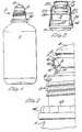
- Figure 7shows a container 31 of substantially identical form to that shown in Figure 1.
- the top of the container(not shown) is sealed in the mould-fill-seal machine and a cap 32 is screw-threaded thereon.
- the cap 32comprises an externally-knurled cylindrical portion 33 attached through a frangible portion 34 of lesser thickness to a lower skirt 35 comprising an upper frusto-conical portion 36 merging into a lower cylindrical portion 37 which, when the cap is screwed fully home on the container neck, seats tightly on an annular shoulder 38 integrally moulded on the container 31.
- the cap 32has not quite reached its fully screwed-on position.
- the portion 37 of the capis provided with an outwardly-directed tear-tab 39, provided with raised ribs 40 to assist manual grasping.
- a line of weakening 42constituted by a portion of thinner section, extends axially between the tear-tab 39 and the frangible portion 34.
- skirt portion 35Internally of the skirt portion 35 is formed a series of inwardly-directed flexible fins 41, each forming an angle with a radius of the cap between 70 and 85°. Fins 41 cooperate with spaced lugs or ratchet teeth formed on the container neck above the shoulder 38, for example of the type designated 13 in Figure 2.
- the cap 32is applied to and removed from the container 31 in the same way as is described in relation to the embodiment of Figures 1 to 6.
Landscapes
- Engineering & Computer Science (AREA)
- Mechanical Engineering (AREA)
- Ceramic Engineering (AREA)
- Closures For Containers (AREA)
Description
- This invention relates to a sterile pack according to the preamble of
claim 1. Such a pack is known from US-A-3784045. - Sterile packs, being the combination of a sterile fluid-containing container having an integral seal at its upper end, and a closure, are known. The container is manufactured, filled with sterile liquid and sealed in a single operation, after which the ciosure is applied. The neck of the container and the closure are so constructed that an initial movement of the closure, before it is removed from the container, breaks the seal on the container.
- In one known method for the production of sterile packs, the container is blow-moulded from a plastics material, for example polypropylene. Sterile fluid, e.g. sterile water, is admitted into the container during the moulding stage and the contents of the container sealed by the formation of an integral seal, normally in the shape of a domed portion, at the upper end of the container. On leaving the mould, the container is therefore formed, filled and sealed. Further heat sterilisation can be achieved by autoclaving, following which a closure is applied to the neck of the container.
- In a known form of pack, the neck of the container is formed with a frangible diaphragm, which is broken by an initial downward movement of the closure, whereafter the closure may be removed in the normal way and the contents of the container exposed. such a pack is disclosed in US-A-3784045. Inadvertent downward movement of the closure may be prevented by means of a pilfer-proof band which must be removed before movement of the closure can be effected. An example of a pilfer-proof band is shown in US-A-3902621. Another form of pack is described in US-A-4157765.
- In practice it has been found that the known packs are not completely reliable. The major disadvantage has been that the frangible membrane has not sheared easily, and has accordingly remained attached to the container when the closure is removed.
- It is the object of the present invention to provide a sterile pack which does not suffer from this disadvantage.
- According to the present invention a sterile pack comprises, in combination, a moulded plastics container to which is attached a moulded plastics cap,
- (i) the container being integrally sealed at its upper end, the neck of the container being provided with thread and an annular portion of the neck above the thread being frangible,
- (ii) the cap having a thread complementary with the container thread and means for contacting the container above the said annular portion, characterised in that the thread has a pitch of between 0.05 and 0.095 millimeters per turn per millimeter of thread diameter, that the diameter of the frangible portion of the container is at most 80% of the thread diameter, and that the cap skirt is provided with a pilfer-proof ring which prevents breakage of said frangible annular portion until the pilfer-proof ring is removed from the cap along a line of weakness joining said ring to said cap skirt.
- In accordance with one embodiment of the invention, the thread has a pitch of at least 0.08 millimeters per turn per millimeter of thread diameter and the diameter of the frangible portion of the container is at most 75% of the thread diameter.
- The pilfer-proof ring provided at the lower end of the cap skirt, and engaging a complementarily- shaped part of the container, prevents inadvertent shearing of the frangible portion. In order to open the container, the pilfer-proof ring is first removed, and the cap is then screwed further onto the container, so that the container-contacting part of the cap above the frangible portion causes relative movement between the top of the container and the remainder thereof, thus breaking the frangible portion of the container. Unscrewing of the cap thereafter removes the sheared-off upper part of the container from the rest of the container, thus exposing the contents of the container. The combination of the fine pitch thread and the diameter of the frangible portion guarantees ready and complete shearing of the frangible portion, and thus opening of the container.
- Preferably the container is moulded with an outwardly-directed annular shoulder beneath the thread on the neck of the container, which shoulder is tightly engaged by the lowermost end of the pilfer-proof ring, when the cap is attached to the container in sealing position. This tight engagement between the pilfer-proof ring and the shoulder formed on the container forms a secondary seal which prevents foreign matter getting between the cap skirt and the neck of the container.
- The pilfer-proof ring may be formed internally with a series of teeth or ratchets which mesh with corresponding teeth or ratchets formed on the container neck, thus rendering the removal of the cap impossible until such time as the pilfer-proof ring has itself been removed, e.g. by tearing, from the cap skirt. Preferably, however, a detachable ring forming the lowermost portion of the cap skirt is provided interiorly with a series of flexible fins which engage with lugs, teeth or other ramp- like formations on the neck of the container, below the thread. Such fin/lug configuration prevents unscrewing removal of the cap from the container until such time as the detachable ring portion of the cap skirt has been removed, in the same way as does the teeth/ratchet formation mentioned above, but has the advantage over the latter that it makes the application of the cap to the container somewhat easier (i.e. less torque is required) and does not suffer the disadvantage that can occur with the more rigid teeth/ratchets which tend, on application of the cap to the container, to wear the contacting parts of each other away. Furthermore, the flexible fin configuration results in there being less stress in the skirt of the cap above the pilfer-proof ring, and thus less likelihood of inadvertent splitting of the pilfer-proof ring between the tear tab by which it removed and the line of weakening separating it from the rest of the cap skirt.
- Reference will now be made to the accompanying drawings, in which:-
- Figure 1 is a side view of a sealed container, before application of a cap thereto;
- Figure 2 is a detailed view, partly in section, of the top of the neck portion of the container of Figure 1;
- Figure 3 is a view, partly in section, of a cap applied to the container of Figure 1;
- Figures 4, 5 and 6 are, respectively, side, underneath and sectional views of the cap shown in Figure 3;
- Figure 7 shows a second embodiment of the pack comprising a moulded plastics container and a moulded plastics cap, just before the cap is screwed tightly onto the container;
- Figure 8 is a side view of the cap of Figure 7, partly in section; and
- Figure 9 is both a top (left-hand side) and an underneath (right-hand side) plan view of the cap of Figures 7 and 8.
- Referring now to Figures 1 and 2, a
container 1 is formed of a plastics material, e.g. polypropylene, in a machine which, during the moulding operation, fills the container with a sterile liquid, e.g. sterile water, and forms an upper part 2 comprising a screw-threaded part 3 and an integrally-formed dome-shaped seal 4. - An inwardly-directed shoulder 5 below the domed portion 4 connects with a
ring portion 6 through a horizontal shoulder 7. At the bottom of thering portion 6 is a shoulder 8, parallel to shoulder 7, having an inverted V-shaped channel 9 forming anannular portion 10 of substantially reduced thickness in comparison with the remainder of the neck portion of the container. Atubular portion 11 merges into a threaded portion 12, below which is a series ofteeth 13 arranged in anannular band 14 around the container neck. The diameter of the annularfrangible portion 10 is at most 80% of the outside diameter of the thread 12. The thread has a pitch of 0.05 to 0.095, preferably at least 0.08, turns per millimeter per millimeter of thread diameter. For example, if the outside diameter of the thread is 37.3 mm. the pitch of the thread may be 3.3 turns per millimeter, and the diameter of the annularfrangible portion 10 may be 25 mm. - The sterile pack is completed by a cap 20 (see Figures 3 to 6) having a
top 21 attached through a frusto-conical portion 22 to an internally-screw-threadedskirt 23. Theskirt 23 is provided exteriorly with coarse knurling 24 and frangibly attached to its lower end, through a weakenedportion 25, is a pilfer-proof band 26. - The pilfer-
proof band 26 is provided internally with a series ofratchets 27 which engage with theteeth 13 on the container in the manner described and illustrated in U.K. Patent specification No. 1,473,257. A tear-ring 28 is internally moulded with theband 26 which may be removed by pulling the tear-ring 28 initially to fracture a weakened portion 29 and then to break theannular weakening line 25. - The cap is formed internally with an annular inwardly-directed
bead 30 which is of such a size as to be snapped over the outer extremity of the dome seal 4 in order to contact the upper shoulder 7 of thering portion 6 of the container neck. - Figure 3 shows the top of the sterile pack in its normal sealed and closed configuration. The pack is opened by the following sequence of steps:-
- (a) the tear-
ring 28 is grasped and pulled to remove the pilfer-proof band 26 from theskirt 23 of the cap; - (b) the cap is screwed further onto the neck of the container, bead 30 passing over dome 4, contacting shoulder 7 and pushing
ring portion 6 downwardly; - (c) continued on-screwing of the cap breaks the annular
frangible portion 10, thus breaking the container seal; - (d) the cap is then unscrewed, and by virtue of the
bead 30 having passed over the dome 4 into the shoulder 5, the portion of the container comprising the dome 4, shoulder 5 andring portion 6 are removed together with the cap. - Referring now to Figures 7 to 9 of the drawings, Figure 7 shows a container 31 of substantially identical form to that shown in Figure 1. The top of the container (not shown) is sealed in the mould-fill-seal machine and a
cap 32 is screw-threaded thereon. Thecap 32 comprises an externally-knurled cylindrical portion 33 attached through afrangible portion 34 of lesser thickness to alower skirt 35 comprising an upper frusto-conical portion 36 merging into a lowercylindrical portion 37 which, when the cap is screwed fully home on the container neck, seats tightly on anannular shoulder 38 integrally moulded on the container 31. As shown in Figure 7, thecap 32 has not quite reached its fully screwed-on position. Theportion 37 of the cap is provided with an outwardly-directed tear-tab 39, provided with raisedribs 40 to assist manual grasping. A line of weakening 42, constituted by a portion of thinner section, extends axially between the tear-tab 39 and thefrangible portion 34. - Internally of the
skirt portion 35 is formed a series of inwardly-directed flexible fins 41, each forming an angle with a radius of the cap between 70 and 85°. Fins 41 cooperate with spaced lugs or ratchet teeth formed on the container neck above theshoulder 38, for example of the type designated 13 in Figure 2. - The
cap 32 is applied to and removed from the container 31 in the same way as is described in relation to the embodiment of Figures 1 to 6. - When moulding the upper portion of the container, i.e. that part designated 2 in Figure 1 of the drawings, it is preferred to form that part of the container above the screw thread without flash, or with as little flash as possible. This assists in achieving a consistent thickness of the frangible portion of the container neck, which assists in the rupture thereof, as described above.
Claims (8)
characterised in that the thread has a pitch of between 0.05 to 0.095 millimeters per turn per millimeter of thread diameter, that the diameter of the frangible portion of the container is at most 80% of the thread diameter, and that the cap skirt is provided with a pilfer-proof ring (26, 35) which prevents breakage of said frangible annular portion until the pilfer-proof ring is removed from the cap along a line of weakness (25, 34) joining said ring to said cap skirt.
Priority Applications (3)
| Application Number | Priority Date | Filing Date | Title |
|---|---|---|---|
| AT81304831TATE21674T1 (en) | 1980-10-17 | 1981-10-16 | STERILE PACK. |
| ES1982263825UES263825Y (en) | 1981-09-16 | 1982-03-10 | A STERILIZED CONTAINER. |
| PT7457482APT74574B (en) | 1981-09-16 | 1982-03-12 | Closure |
Applications Claiming Priority (4)
| Application Number | Priority Date | Filing Date | Title |
|---|---|---|---|
| GB8033670 | 1980-10-17 | ||
| GB8033670 | 1980-10-17 | ||
| GB8127969 | 1981-09-16 | ||
| GB8127969 | 1981-09-16 |
Publications (2)
| Publication Number | Publication Date |
|---|---|
| EP0050490A1 EP0050490A1 (en) | 1982-04-28 |
| EP0050490B1true EP0050490B1 (en) | 1986-08-27 |
Family
ID=26277258
Family Applications (1)
| Application Number | Title | Priority Date | Filing Date |
|---|---|---|---|
| EP81304831AExpiredEP0050490B1 (en) | 1980-10-17 | 1981-10-16 | Sterile pack |
Country Status (3)
| Country | Link |
|---|---|
| US (1) | US4402415A (en) |
| EP (1) | EP0050490B1 (en) |
| DE (1) | DE3175224D1 (en) |
Families Citing this family (57)
| Publication number | Priority date | Publication date | Assignee | Title |
|---|---|---|---|---|
| DE3149780C2 (en)* | 1981-12-16 | 1987-02-19 | Gerhard 7166 Sulzbach-Laufen Hansen | Containers, especially plastic bottles |
| FR2546484B2 (en)* | 1983-03-07 | 1986-05-09 | Cebal | CONTAINER WITH TAMPER-RESISTANT FLIPPABLE SKIRT WITH INTERIOR CAP |
| US4478342A (en)* | 1983-07-14 | 1984-10-23 | Baxter Travenol Laboratories, Inc. | Sterilizable container with inner closure and collapse-resistant cover |
| US4526279A (en)* | 1983-10-06 | 1985-07-02 | Automatic Liquid Packaging, Inc. | Severing overcap for container |
| DE3336612A1 (en)* | 1983-10-07 | 1985-04-25 | Milupa Ag, 6382 Friedrichsdorf | OPENING AND REMOVAL CAP |
| US4546893A (en)* | 1984-10-22 | 1985-10-15 | Gene Stull | Tamper-evident closure cap construction |
| US4655355A (en)* | 1984-12-24 | 1987-04-07 | Baxter Travenol Laboratories, Inc. | Container including inner closure with opening permitting free liquid flow |
| GB8505237D0 (en)* | 1985-02-28 | 1985-04-03 | Schering Chemicals Ltd | Bottles |
| CH669575A5 (en)* | 1985-08-20 | 1989-03-31 | Alfatechnic Ag | |
| US4721215A (en)* | 1986-01-08 | 1988-01-26 | Abbott Laboratories | Expandable ring closure device |
| DE3818475A1 (en)* | 1988-05-31 | 1989-12-21 | Hans Heinlein | CLOSURE FOR A BOTTLE-LIKE CONTAINER, ESPECIALLY FOR OPERATING RINSE WATER OD. DGL. |
| FR2653746A1 (en)* | 1989-10-26 | 1991-05-03 | Merck Sharp & Dohme | STERILE PACKAGING ASSEMBLY FOR DISPENSING LIQUID, AND METHOD FOR MANUFACTURING SUCH A ASSEMBLY. |
| US5165559A (en)* | 1990-02-01 | 1992-11-24 | Owens-Illinois Closure Inc. | Child resistant closure and package |
| US5213224A (en)* | 1990-08-09 | 1993-05-25 | Portola Packaging, Inc. | Snap-on, screw-off cap and container neck |
| US20050269282A1 (en)* | 1990-08-09 | 2005-12-08 | Portola Packaging, Inc. | Tamper-evident cap and container neck |
| US5975321A (en)* | 1990-08-09 | 1999-11-02 | Portola Packaging, Inc. | Snap-on, screw-off cap with tamper-evidencing skirt and container neck |
| US5415306A (en)* | 1990-08-09 | 1995-05-16 | Portola Packaging, Inc. | Foil lined snap-on, screw-off closure and container neck |
| US5456376A (en)* | 1990-08-09 | 1995-10-10 | Portola Packaging, Inc. | Snap-on, screw off cap and container neck |
| US5687866A (en)* | 1990-08-09 | 1997-11-18 | Cap Snap Co. | Snap-on, screw-off cap and container neck |
| FR2665886B1 (en)* | 1990-08-14 | 1992-10-16 | Cebal | ASSEMBLY OF AN OPENING CAPSULE AND A CONTAINER WITH A TAMPER-FREE LID. |
| US5111947A (en)* | 1990-12-04 | 1992-05-12 | Patterson Michael C | Tamper proof cap and container |
| US5100011A (en)* | 1991-04-05 | 1992-03-31 | The West Company, Incorporated | Tamper evident closure |
| CA2077722A1 (en)* | 1992-07-31 | 1994-02-01 | Luca Molinaro | Snap on pull off tamper-indicating flexible cap for containers |
| US5560504A (en)* | 1993-03-24 | 1996-10-01 | Molinaro; Luca | Snap on pull off tamper indicating flexible cap and neck configuration |
| US5480045A (en)* | 1993-03-24 | 1996-01-02 | Portola Packaging, Inc. | Neck finish for a container and a matching registering multiple thread pattern in a flexible cap for engagement on said neck finish |
| USRE37243E1 (en)* | 1993-03-24 | 2001-06-26 | Portola Packaging, Inc. | Neck finish for a container and a matching registering multiple thread pattern in a flexible cap for engagement on said neck finish |
| US5307946A (en)* | 1993-03-24 | 1994-05-03 | Northern Engineering & Plastics, Corp. | Neck finish for a container and a matching registering multiple thread pattern in a flexible cap for engagement on neck said finish |
| US5456374A (en)* | 1994-09-19 | 1995-10-10 | Beck; Matthew R. | Tamper evident container closure |
| US5685444A (en)* | 1995-09-19 | 1997-11-11 | Valley; Joseph P. | Tamper-evident hinged closure cap construction |
| ES1032168Y (en)* | 1995-09-28 | 1996-10-16 | C T X S A | CONTAINER WITH SAFETY LID AND SEAL. |
| US5680965A (en)* | 1996-01-29 | 1997-10-28 | Beck; Matthew R. | Tamper evident container closure |
| US6073809A (en)* | 1996-02-15 | 2000-06-13 | International Plastics And Equipment Corporation | Snap-on tamper evident closure with push-pull pour spout |
| US5862953A (en)* | 1996-04-16 | 1999-01-26 | International Plastics And Equipment Corporation | Tamper evident push-pull closure with pour spout |
| US6192569B1 (en)* | 1996-04-22 | 2001-02-27 | Cebal Sa | Process for manufacture of a top for a container with a detachable cover reusable as a cap |
| MXPA00004145A (en) | 1997-10-30 | 2003-08-01 | Internat Plastics And Equipmen | Tortilla counter-stacker whit ballistic stacking. |
| US6523710B1 (en)* | 1998-02-04 | 2003-02-25 | Walter E. Hidding | Tamper resistant bottle cap and neck |
| US8495854B2 (en)* | 2001-09-04 | 2013-07-30 | Obrist Closures Switzerland Gmbh | Crown-like twist-off closure |
| US20040045925A1 (en)* | 2002-09-11 | 2004-03-11 | Seidita Thomas M. | Tamper evident closure with locking band |
| US7637384B2 (en)* | 2002-08-09 | 2009-12-29 | Crown Packaging Technology, Inc. | Tamper evident closure with locking band and container therefor |
| USD515922S1 (en) | 2003-07-01 | 2006-02-28 | Crown Cork & Seal Technologies, Corporation | Closure cap |
| USD535189S1 (en) | 2003-07-01 | 2007-01-16 | Crown Cork & Seal Technologies Corporation | Closure cap |
| USD510523S1 (en) | 2003-07-01 | 2005-10-11 | Crown Cork & Seal Technologies Corporation | Closure cap |
| USD508650S1 (en) | 2003-07-01 | 2005-08-23 | Crown Cork & Seal Technologies Corporation | Closure cap |
| USD519373S1 (en) | 2003-07-01 | 2006-04-25 | Crown Cork & Seal Technologies Corporation | Closure cap |
| USD510269S1 (en) | 2003-07-01 | 2005-10-04 | Crown Cork & Seal Technologies, Corporation | Closure cap |
| USD515923S1 (en) | 2003-07-01 | 2006-02-28 | Crown Cork & Seal Technologies, Corporation | Closure cap |
| USD513586S1 (en) | 2003-07-01 | 2006-01-17 | Crown Cork & Seal Technologies, Corporation | Closure cap |
| US7188750B2 (en)* | 2003-09-05 | 2007-03-13 | Hospira, Inc. | Blow fill sealed container with twist off top operated by overcap and method of forming the same |
| US20050167389A1 (en)* | 2004-02-04 | 2005-08-04 | Price Michael L. | Closure with improved resistance to deformation during opening |
| USD538654S1 (en) | 2004-04-30 | 2007-03-20 | Crown Packaging Technology, Inc. | Crown-like plastic closure |
| USD537719S1 (en) | 2004-07-19 | 2007-03-06 | Crown Packaging Technology, Inc. | Crown-like plastic closure |
| DE102005025760A1 (en)* | 2005-06-04 | 2006-12-07 | Bernd Hansen | container |
| WO2007126062A1 (en)* | 2006-04-28 | 2007-11-08 | Tokan Kogyo Co., Ltd. | Cap and container with cap |
| ITMO20070192A1 (en) | 2007-06-05 | 2008-12-06 | Sacmi | MEANS OF CLOSING |
| RU2357147C2 (en)* | 2007-08-06 | 2009-05-27 | Федеральное Государственное унитарное предприятие "Государственное научно-производственное предприятие "Сплав" | Vessel that operates under pressure |
| EP3434616B1 (en)* | 2017-07-25 | 2020-04-01 | Incap International Ltd. | Closure cap for a container |
| DE102018108491A1 (en)* | 2018-04-10 | 2019-10-10 | Bericap Holding Gmbh | Counterfeit-proof screw cap |
Family Cites Families (10)
| Publication number | Priority date | Publication date | Assignee | Title |
|---|---|---|---|---|
| FR1526780A (en)* | 1964-05-26 | 1968-05-31 | Plastiflor Soc | Tamper-evident sealing cap of flexible plastic or similar material |
| US3650428A (en)* | 1970-04-09 | 1972-03-21 | V C A Corp | Tamperproof closure device |
| US3784045A (en)* | 1971-10-26 | 1974-01-08 | Automatic Liquid Packaging | Permanently sealed containers and end caps therefor |
| FR2192954B1 (en)* | 1972-07-18 | 1976-08-06 | Astra Plastique | |
| US3837518A (en)* | 1972-11-30 | 1974-09-24 | Sunbeam Plastics Corp | Tamper-proof and child-proof medicine bottle or the like |
| US3902621A (en)* | 1974-08-05 | 1975-09-02 | Walter E Hidding | Tamperproof closure with grippable handle |
| US3980195A (en)* | 1974-11-18 | 1976-09-14 | Owens-Illinois, Inc. | Tamper-proof closure |
| US4111325A (en)* | 1977-03-14 | 1978-09-05 | Baxter Travenol Laboratories, Inc. | Sealed closure for plastic container with interlocking protective outer closure |
| FR2407141A1 (en)* | 1977-10-28 | 1979-05-25 | Cebal | INVIOLABILITY DEVICE FOR CONTAINERS WHOSE THOUGHT IS CLOSED BY A SCREWED CAPSULE |
| US4176755A (en)* | 1979-01-26 | 1979-12-04 | Baxter Travenol Laboratories, Inc. | Resealable pour bottle with severing ring |
- 1981
- 1981-10-16EPEP81304831Apatent/EP0050490B1/ennot_activeExpired
- 1981-10-16DEDE8181304831Tpatent/DE3175224D1/ennot_activeExpired
- 1981-10-16USUS06/312,072patent/US4402415A/ennot_activeExpired - Fee Related
Also Published As
| Publication number | Publication date |
|---|---|
| US4402415A (en) | 1983-09-06 |
| DE3175224D1 (en) | 1986-10-02 |
| EP0050490A1 (en) | 1982-04-28 |
Similar Documents
| Publication | Publication Date | Title |
|---|---|---|
| EP0050490B1 (en) | Sterile pack | |
| US5415306A (en) | Foil lined snap-on, screw-off closure and container neck | |
| US6637611B2 (en) | Snap-on, screw-off cap and container neck | |
| EP0117104B1 (en) | Method for manufacturing a tamper evident-closure | |
| US5213224A (en) | Snap-on, screw-off cap and container neck | |
| KR100436629B1 (en) | Cap detachable from container for disposal | |
| US5660290A (en) | Closure fitting for unthreaded containers | |
| CA1305100C (en) | Tamper-evident buttress plug closure | |
| US7198170B2 (en) | Closure and container system and method for sealing a closure on a container | |
| EP1025014B1 (en) | Sports beverage snap closure | |
| RU2213683C2 (en) | Container cap unit | |
| US5887738A (en) | Foil lined snap-on, screw-off closure and container neck | |
| EP1327588B1 (en) | Closure with pressure release system | |
| KR100586748B1 (en) | Plastic cap | |
| EP0194068B1 (en) | Bottles | |
| WO1994020380A1 (en) | Snap-on, screw off cap and container neck | |
| US4225050A (en) | Tamper-proof bottle caps and method of forming same | |
| US5687866A (en) | Snap-on, screw-off cap and container neck | |
| CA1089414A (en) | Hermetic safety seal for bottles and the like, in particular for fizzy drink bottles | |
| JPH0375423B2 (en) | ||
| JP3727675B2 (en) | Synthetic resin container lid with tamper evident characteristics | |
| JP3106332B2 (en) | Synthetic resin container lid | |
| JP4762426B2 (en) | Separable disposal cap | |
| EP0235870B1 (en) | Tamper-evident closures | |
| JP4068189B2 (en) | Plastic container lid |
Legal Events
| Date | Code | Title | Description |
|---|---|---|---|
| PUAI | Public reference made under article 153(3) epc to a published international application that has entered the european phase | Free format text:ORIGINAL CODE: 0009012 | |
| AK | Designated contracting states | Designated state(s):AT BE CH DE FR GB IT LU NL SE | |
| 17P | Request for examination filed | Effective date:19821001 | |
| GRAA | (expected) grant | Free format text:ORIGINAL CODE: 0009210 | |
| AK | Designated contracting states | Kind code of ref document:B1 Designated state(s):AT BE CH DE FR GB IT LI LU NL SE | |
| PG25 | Lapsed in a contracting state [announced via postgrant information from national office to epo] | Ref country code:NL Effective date:19860827 Ref country code:IT Free format text:LAPSE BECAUSE OF FAILURE TO SUBMIT A TRANSLATION OF THE DESCRIPTION OR TO PAY THE FEE WITHIN THE PRESCRIBED TIME-LIMIT;WARNING: LAPSES OF ITALIAN PATENTS WITH EFFECTIVE DATE BEFORE 2007 MAY HAVE OCCURRED AT ANY TIME BEFORE 2007. THE CORRECT EFFECTIVE DATE MAY BE DIFFERENT FROM THE ONE RECORDED. Effective date:19860827 Ref country code:BE Effective date:19860827 Ref country code:AT Effective date:19860827 | |
| REF | Corresponds to: | Ref document number:21674 Country of ref document:AT Date of ref document:19860915 Kind code of ref document:T | |
| PG25 | Lapsed in a contracting state [announced via postgrant information from national office to epo] | Ref country code:SE Effective date:19860831 | |
| REF | Corresponds to: | Ref document number:3175224 Country of ref document:DE Date of ref document:19861002 | |
| ET | Fr: translation filed | ||
| PG25 | Lapsed in a contracting state [announced via postgrant information from national office to epo] | Ref country code:LU Free format text:LAPSE BECAUSE OF NON-PAYMENT OF DUE FEES Effective date:19861031 | |
| REG | Reference to a national code | Ref country code:CH Ref legal event code:PL | |
| PLBI | Opposition filed | Free format text:ORIGINAL CODE: 0009260 | |
| NLV1 | Nl: lapsed or annulled due to failure to fulfill the requirements of art. 29p and 29m of the patents act | ||
| 26 | Opposition filed | Opponent name:FRANZ POHL METALL- UND KUNSTSTOFFWARENFABRIK GMBH Effective date:19870123 | |
| PG25 | Lapsed in a contracting state [announced via postgrant information from national office to epo] | Ref country code:GB Effective date:19891016 | |
| GBPC | Gb: european patent ceased through non-payment of renewal fee | ||
| RDAG | Patent revoked | Free format text:ORIGINAL CODE: 0009271 | |
| STAA | Information on the status of an ep patent application or granted ep patent | Free format text:STATUS: PATENT REVOKED | |
| 27W | Patent revoked | Effective date:19900406 | |
| GBPR | Gb: patent revoked under art. 102 of the ep convention designating the uk as contracting state | ||
| REG | Reference to a national code | Ref country code:FR Ref legal event code:ST | |
| REG | Reference to a national code | Ref country code:CH Ref legal event code:PL |