EP0050048B1 - Anchoring a railway rail-fastening clip to a foundation for a railway rail - Google Patents
Anchoring a railway rail-fastening clip to a foundation for a railway railDownload PDFInfo
- Publication number
- EP0050048B1 EP0050048B1EP81304819AEP81304819AEP0050048B1EP 0050048 B1EP0050048 B1EP 0050048B1EP 81304819 AEP81304819 AEP 81304819AEP 81304819 AEP81304819 AEP 81304819AEP 0050048 B1EP0050048 B1EP 0050048B1
- Authority
- EP
- European Patent Office
- Prior art keywords
- projections
- projection
- tail part
- railway rail
- foundation
- Prior art date
- Legal status (The legal status is an assumption and is not a legal conclusion. Google has not performed a legal analysis and makes no representation as to the accuracy of the status listed.)
- Expired
Links
- 238000004873anchoringMethods0.000titleclaimsdescription33
- 210000001364upper extremityAnatomy0.000claimsdescription5
- 238000005452bendingMethods0.000claimsdescription3
- 239000002184metalSubstances0.000claimsdescription2
- 229910052751metalInorganic materials0.000claimsdescription2
- 230000007704transitionEffects0.000claimsdescription2
- 229910001141Ductile ironInorganic materials0.000description1
- 241001669679EleotrisSpecies0.000description1
- 229910000831SteelInorganic materials0.000description1
- 239000010959steelSubstances0.000description1
Images


Classifications
- E—FIXED CONSTRUCTIONS
- E01—CONSTRUCTION OF ROADS, RAILWAYS, OR BRIDGES
- E01B—PERMANENT WAY; PERMANENT-WAY TOOLS; MACHINES FOR MAKING RAILWAYS OF ALL KINDS
- E01B9/00—Fastening rails on sleepers, or the like
- E01B9/02—Fastening rails, tie-plates, or chairs directly on sleepers or foundations; Means therefor
- E01B9/28—Fastening on wooden or concrete sleepers or on masonry with clamp members
- E01B9/30—Fastening on wooden or concrete sleepers or on masonry with clamp members by resilient steel clips
- E01B9/303—Fastening on wooden or concrete sleepers or on masonry with clamp members by resilient steel clips the clip being a shaped bar
Definitions
- an anchoring devicewhich is suitable for use in anchoring a railway rail-fastening clip to a foundation for a railway rail, the device comprising, when considered whilst in a particular orientation, a head part which is to lie above the foundation and is constructed to anchor a railway rail-fastening clip, a tail part which is joined to the head part and is to lie in the foundation and is in the form of a single vertical rod below the head part, and a projection, for resisting forces tending to pull the anchoring device vertically out of the foundation, projecting laterally from the tail part.
- a deviceis known for example from US-A-3297253.
- the inventionaims at improving the quality of the anchorage and is characterised in that the top of the projection extends, from the root of the projection towards its tip, horizontally or at a small angle to the horizontal and in that at a location above the projection there is a vane, for resisting forces tending to turn the anchoring device about a vertical axis, joined along its upper extremity to the bottom of the head part and joined along one side thereof to one side of the upper portion of the tail part, the vane having an overall vertical height and an overall horizontal width which are both greater than its average horizontal thickness.
- a horizontal straight passagewayfor example of circular cross-section, in the head part into which can be driven a substantially straight and horizontal leg of a railway rail-fastening clip which has been made by bending a metal rod.
- the clipmay be any of those shown in United States Patent Specifications Nos. 3,297,253, 3,658,246 and 4,073,435.
- the second vaneis joined along its upper extremity to the bottom of the head part and joined along one side thereof to the side of the upper portion of the tail part which is opposite to said one side of the upper portion of the tail part, the second vane also having an overall vertical height and an overall horizontal width which are both greater than its average horizontal thickness, and the two vanes extending in opposite directions away from the tail part and the median vertical planes of the two vanes being coincident.
- the coincident median vertical planespreferably contain its axis.
- a second projectionfor resisting forces tending to pull the anchoring device vertically out of the foundation, projecting laterally from the tail part at a location lower than the vane, the top of the projection extending, from the root of the projection towards its tip, horizontally or at a small angle to the horizontal, said second projection extending from that side of the tail part which is opposite to that side from which the first-mentioned projection extends and the two projections extending in opposite directions away from the tail part.
- the directions in which the two vanes extend away from the tail partare preferably perpendicular to the directions in which the two projections extend away from the tail part. Examples of this are shown in Figures 5 and 6 and in Figures 7 and 8 of the accompanying drawings (vanes 40 and 41 and projections 50 and 52).
- third and fourth projectionsmay be, in addition to the first-mentioned and second projections extending in opposite directions away from the tail part, third and fourth projections, each as specified above for the first-mentioned projection, extending from opposite sides of the tail part in opposite directions which are perpendicular to the directions in which the first and second projections extend from the tail part.
- An example of thisis also shown in Figures 5 and 6 of the accompanying drawings (projections 50 and 52 and projections 45 and 46), which also show that the four projections may also be at the same vertical distance below the head part.
- the top of the first-mentioned projection or of each projectionmay extend, from the root of the projection to its tip, horizontally or at a small angle, less than 30° and preferably no more than 20°, to the horizontal, preferably downwardly.
- the first-mentioned projection or each or some of the projectionsmay be of substantially saw-tooth form or may have at its tip a vertical face. In either case the tip of the projection is preferably at least 7.5 mm from the root of the projection, measured horizontally.
- a concrete railway rail tiealso known as a railway sleeper
- four anchoring devicesaccording to the first aspect of the invention with their tail parts embedded in the concrete and their head parts above the concrete.
- a railway rail-and-fastening assemblycomprising a concrete foundation for a railway rail, a railway rail lying on the foundation, the rail having a flange at its bottom, two anchoring devices with tail parts embedded in the concrete and head parts above the concrete on opposite sides of the rail, and two railway rail-fastening clips each having one portion anchored by the head part of one of the devices and pressing upwardly on it, another portion bearing downwardly on the top of said flange and a third portion bearing downwardly on said head part at a location which is beyond said one portion, as seen from the rail, characterised in that the anchoring devices are in accbrdance with the first aspect of the invention.
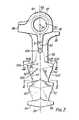
- Figure 1shows a head part 18 of a clip-anchoring device which has joined to it a tail part which is embedded in a concrete rail tie 14.
- a railway rail 10has a flange 12 at its base and this lies between, and is located by, the illustrated head part 18 and the head part 18 of a similar clip-anchoring device (not shown).
- a railway rail-fastening clip 1as shown in Patent No.
- 4,073,435made by bending a steel bar of circular cross-section, has its substantially straight leg 2 lying in a horizontal passageway 20, also of circular cross-section, through the head part 18 and pressing upwardly with a force F 2 on the roof of the passageway.
- a portion 3 of the clippresses downwardly with a force F, on a ledge 36 on the anchoring device and a portion 16 of the clip bears downwardly with a force F on the top of one side of the flange 12.
- a similar clipholds down the other side of the flange 12 and two more such clips hold down the other rail on the same tie.
- the conventional clip-anchoring device shown in Figure 2has a ledge 38 which helps locate the clip-anchoring device in a mould in which the concrete is cast.
- the tail part 22 of the clip-anchoring deviceis in the form of a vertical rod which has rounded projections 22A, the upper flanks 22B and lower flanks 22C of which are inclined by large angles (more than 60°) to the horizontal.
- the projectionsare intended to prevent the clip-anchoring device moving vertically upwardly but experience has shown that vibration sometimes causes the surrounding concrete to crack and the clip-anchoring device to move vertically upwardly.
- each of the devices shown in Figure 3 to 6has two vanes 40 and 41, each of which is joined along its upper extremity 4 to the bottom of the head part 18, which again has a ledge 36 and a passageway 20 through it; there is again another ledge 38.
- Each vane 40 and 41is also joined along one side 5 to the rod-like tail part 39 of the clip-anchoring device.
- the opposite faces of the two vanesare planar but not parallel to each other.
- each vanedisregarding a fillet 7 at the bottom of the vane, is more than 1 t cm and in fact about 2.5 cm, which is about a fifth of the length of the tail part 39, and the overall horizontal width 8 of each vane is more than 1 t cm and in fact about 2.5 cm, i.e. both dimensions are greater than the average horizontal thickness 9 of the vane, which is less than 1'-a cm and in fact about 1.0 cm.
- the total area of each vane as seen in Figures 4 and 6is very much greater than the area of the ledge 38 as seen in Figure 2 and presents a much greater opposition to turning of the clip-anchoring device about its vertical axis.
- the thickness of the tail part 39reduces, proceeding from top to bottom, as shown in Figures 4 and 6, and there are rounded projections 44, somewhat like the projections 22A of Figure 2, below the vanes 40 and 41.
- planar projections 45 and 46each of saw-tooth form, with their upper flanks sloping downwardly from their roots 47 to their tips 48 at a very small angle, less than 5°, to the horizontal.
- the plane 23is the median plane of each of the vanes 40 and 41 and of each of the projections 45 and 46 and it contains the axis 24 of the passageway 20.
- the projections 45 and 46extending away from the tail part 39 in opposite directions, are the only such projections and the width of the lower end 42 of the tail part 39 is greater than the width of the tail part half-way up its length, or indeed at any level below the ledge 38, there being a smooth transition in width from the lower end 42 to the level half-way up the length of the tail part 39.
- FIG. 5 and 6there are two further planar projections 50 and 52, also of saw-tooth form, extending in opposite directions away from the tail part 39, with their upper surfaces also sloping downwardly at a very small angle to the horizontal, proceeding from the roots to the tips of the projections.
- These projectionshave a common median plane 25 which is perpendicular to the plane 23 and the tops of all the projections 45, 46, 50 and 52 are at equal distances below the head part 18.
- Each of the clip-anchoring devices shown in Figures 3 to 6is a single piece of cast spheroidal graphite iron.
- the vanes 40 and 41each have an overall height, 6A or 6B, of more than 2t cm, the overall height 6A of the vane 41 being about 3 cm and the overall height 6B of the vane 40 being about 4 cm.
- the overall width 8A or 8B of each of the vanes 40 and 41is greater than 2t cm and in fact about 3 cm.
- the average thickness 9 of each vaneis about 0.9 cm.
- the lower sides 40A and 41 A of the vanesare inclined to the horizontal and these sides and the almost vertical sides are bevelled, as shown in Figures 8 and 11.
- the projections 50 and 52have planar upper flanks 50B and 52B inclined downwardly, from the roots 47 of the projections to the tips of the projections, at about 10° to the horizontal and this is true also of the projections 54, 56, 60 and 62.
- the tips 50A and 52A of the projections 50 and 52are vertical faces and this is true also of the projections 54, 56, 60 and 62.
- the lower flanks 50C and 52C of the projections 50 and 52are planar and inclined to the vertical, the projections 60 and 62 being similar and the lower flanks of the projections 54 and 56 also being planar but being more nearly horizontal and meeting in a ridge at the bottom of the device.
- vanes and projections shown in Figures 7 and 8has been chosen to avoid interference between them and prestressing or post-stressing wires in the concrete.
- Two recesses 80 and 81, with a rib 82 between them,are formed in the upper surface of the device.
- Each of the projections 45, 46, 50, 52, 54, 56, 60 and 62has a maximum thickness 11, measured horizontally from its root to its tip, of about 1 cm. It is considered that this thickness must be at least 0.5 cm, better still at least 0.75 cm.
Landscapes
- Engineering & Computer Science (AREA)
- Mechanical Engineering (AREA)
- Architecture (AREA)
- Civil Engineering (AREA)
- Structural Engineering (AREA)
- Railway Tracks (AREA)
- Joining Of Building Structures In Genera (AREA)
- Piles And Underground Anchors (AREA)
- Foundations (AREA)
Description
- According to a first aspect of the invention, there is provided an anchoring device which is suitable for use in anchoring a railway rail-fastening clip to a foundation for a railway rail, the device comprising, when considered whilst in a particular orientation, a head part which is to lie above the foundation and is constructed to anchor a railway rail-fastening clip, a tail part which is joined to the head part and is to lie in the foundation and is in the form of a single vertical rod below the head part, and a projection, for resisting forces tending to pull the anchoring device vertically out of the foundation, projecting laterally from the tail part. Such a device is known for example from US-A-3297253. The invention aims at improving the quality of the anchorage and is characterised in that the top of the projection extends, from the root of the projection towards its tip, horizontally or at a small angle to the horizontal and in that at a location above the projection there is a vane, for resisting forces tending to turn the anchoring device about a vertical axis, joined along its upper extremity to the bottom of the head part and joined along one side thereof to one side of the upper portion of the tail part, the vane having an overall vertical height and an overall horizontal width which are both greater than its average horizontal thickness.
- There may be a horizontal straight passageway, for example of circular cross-section, in the head part into which can be driven a substantially straight and horizontal leg of a railway rail-fastening clip which has been made by bending a metal rod. The clip may be any of those shown in United States Patent Specifications Nos. 3,297,253, 3,658,246 and 4,073,435.
- Preferably, there is a second vane joined along its upper extremity to the bottom of the head part and joined along one side thereof to the side of the upper portion of the tail part which is opposite to said one side of the upper portion of the tail part, the second vane also having an overall vertical height and an overall horizontal width which are both greater than its average horizontal thickness, and the two vanes extending in opposite directions away from the tail part and the median vertical planes of the two vanes being coincident. If the head part includes the above-mentioned passageway, the coincident median vertical planes preferably contain its axis.
- There is preferably a second projection, for resisting forces tending to pull the anchoring device vertically out of the foundation, projecting laterally from the tail part at a location lower than the vane, the top of the projection extending, from the root of the projection towards its tip, horizontally or at a small angle to the horizontal, said second projection extending from that side of the tail part which is opposite to that side from which the first-mentioned projection extends and the two projections extending in opposite directions away from the tail part. If there are both the two vanes and the two projections, the directions in which the two vanes extend away from the tail part are preferably perpendicular to the directions in which the two projections extend away from the tail part. Examples of this are shown in Figures 5 and 6 and in Figures 7 and 8 of the accompanying drawings (
vanes projections 50 and 52). - There may be, in addition to the first-mentioned and second projections extending in opposite directions away from the tail part, third and fourth projections, each as specified above for the first-mentioned projection, extending from opposite sides of the tail part in opposite directions which are perpendicular to the directions in which the first and second projections extend from the tail part. An example of this is also shown in Figures 5 and 6 of the accompanying drawings (
projections projections 45 and 46), which also show that the four projections may also be at the same vertical distance below the head part. - There may be at least one projection, as specified above for the first-mentioned projection, at a greater distance than is the first-mentioned projection from the head part. Thus there may be an upper pair of oppositely-directed projections and a lower pair of oppositely-directed projections, all having coincident median planes. See Figure 5 of the accompanying drawings (
projections projections 54 and 56) which also shows another pair of oppositely-directed projections (45 and 46) having coincident median planes perpendicular to the median planes of theprojections - The top of the first-mentioned projection or of each projection may extend, from the root of the projection to its tip, horizontally or at a small angle, less than 30° and preferably no more than 20°, to the horizontal, preferably downwardly.
- The first-mentioned projection or each or some of the projections may be of substantially saw-tooth form or may have at its tip a vertical face. In either case the tip of the projection is preferably at least 7.5 mm from the root of the projection, measured horizontally.
- According to a second aspect of the invention, there is provided a concrete railway rail tie (also known as a railway sleeper), characterised by four anchoring devices according to the first aspect of the invention with their tail parts embedded in the concrete and their head parts above the concrete.
- According to a third aspect of the invention, there is provided a railway rail-and-fastening assembly comprising a concrete foundation for a railway rail, a railway rail lying on the foundation, the rail having a flange at its bottom, two anchoring devices with tail parts embedded in the concrete and head parts above the concrete on opposite sides of the rail, and two railway rail-fastening clips each having one portion anchored by the head part of one of the devices and pressing upwardly on it, another portion bearing downwardly on the top of said flange and a third portion bearing downwardly on said head part at a location which is beyond said one portion, as seen from the rail, characterised in that the anchoring devices are in accbrdance with the first aspect of the invention.
- examples in accordance with the invention are described below with reference to the accompanying drawings, in which:-
- Figure 1 diagrammatically shows part of a concrete rail tie according to the second aspect of the invention and part of a railway rail-and-fastening assembly according to the third aspect of the invention,
- Figure 2 shows a conventional clip-anchoring device which has hitherto been included in a rail tie and an assembly as shown in Figure 1,
- Figures 3, 5 and 7 show side elevations of a first, a second and a third clip-anchoring device according to the first aspect of the invention,
- Figures 4, 6 and 8 show further side elevations of the devices according to Figures 3, 5 and 7, respectively,
- Figures 9, 10 and 11 show the shapes of cross-section of the device depicted in Figures 7 and 8, at the places indicated by the arrows IX, X and XI, respectively, in those figures, and
- Figure 12 shows a plan view of the same device.
- Figure 1 shows a
head part 18 of a clip-anchoring device which has joined to it a tail part which is embedded in aconcrete rail tie 14. Arailway rail 10 has aflange 12 at its base and this lies between, and is located by, the illustratedhead part 18 and thehead part 18 of a similar clip-anchoring device (not shown). There are two further such clip-anchoring devices (not shown) further to the right, with the flange of the other rail lying between the head parts and with their tail parts embedded in the concrete tie. A railway rail-fastening clip 1 as shown in Patent No. 4,073,435, made by bending a steel bar of circular cross-section, has its substantiallystraight leg 2 lying in ahorizontal passageway 20, also of circular cross-section, through thehead part 18 and pressing upwardly with a force F2 on the roof of the passageway. A portion 3 of the clip presses downwardly with a force F, on aledge 36 on the anchoring device and aportion 16 of the clip bears downwardly with a force F on the top of one side of theflange 12. A similar clip holds down the other side of theflange 12 and two more such clips hold down the other rail on the same tie. - The conventional clip-anchoring device shown in Figure 2 has a
ledge 38 which helps locate the clip-anchoring device in a mould in which the concrete is cast. Thetail part 22 of the clip-anchoring device is in the form of a vertical rod which hasrounded projections 22A, theupper flanks 22B andlower flanks 22C of which are inclined by large angles (more than 60°) to the horizontal. The projections are intended to prevent the clip-anchoring device moving vertically upwardly but experience has shown that vibration sometimes causes the surrounding concrete to crack and the clip-anchoring device to move vertically upwardly. There is also a tendency for the concrete to crack due to forces tending to turn the clip-anchoring device about the vertical axis of thetail part 22, despite the presence of theledge 38 which opposes, to a very limited extent, such turning. - In order to resist to a greater extent forces tending to turn the clip-anchoring device about the vertical axis, each of the devices shown in Figure 3 to 6 has two
vanes upper extremity 4 to the bottom of thehead part 18, which again has aledge 36 and apassageway 20 through it; there is again anotherledge 38. Eachvane side 5 to the rod-like tail part 39 of the clip-anchoring device. The opposite faces of the two vanes are planar but not parallel to each other. - The overall
vertical height 6 of each vane, disregarding a fillet 7 at the bottom of the vane, is more than 1 t cm and in fact about 2.5 cm, which is about a fifth of the length of thetail part 39, and the overallhorizontal width 8 of each vane is more than 1 t cm and in fact about 2.5 cm, i.e. both dimensions are greater than the average horizontal thickness 9 of the vane, which is less than 1'-a cm and in fact about 1.0 cm. Thus the total area of each vane as seen in Figures 4 and 6 is very much greater than the area of theledge 38 as seen in Figure 2 and presents a much greater opposition to turning of the clip-anchoring device about its vertical axis. - In each case the thickness of the
tail part 39 reduces, proceeding from top to bottom, as shown in Figures 4 and 6, and there arerounded projections 44, somewhat like theprojections 22A of Figure 2, below thevanes planar projections roots 47 to theirtips 48 at a very small angle, less than 5°, to the horizontal. Theplane 23 is the median plane of each of thevanes projections axis 24 of thepassageway 20. - In the case shown in Figures 3 and 4, the
projections tail part 39 in opposite directions, are the only such projections and the width of thelower end 42 of thetail part 39 is greater than the width of the tail part half-way up its length, or indeed at any level below theledge 38, there being a smooth transition in width from thelower end 42 to the level half-way up the length of thetail part 39. - In the case shown in Figures 5 and 6 there are two further
planar projections tail part 39, with their upper surfaces also sloping downwardly at a very small angle to the horizontal, proceeding from the roots to the tips of the projections. These projections have a commonmedian plane 25 which is perpendicular to theplane 23 and the tops of all theprojections head part 18. There are two furtherplanar projections tail part 39, extending in opposite directions away from it and having theplane 25 as their common median plane. These projections have their tops inclined to the horizontal by a larger angle than theother projections - Each of the clip-anchoring devices shown in Figures 3 to 6 is a single piece of cast spheroidal graphite iron.
- The device shown in Figures 7 to 12 is somewhat similar to that of Figures 5 and 6 and corresponding parts are similarly numbered. The principal differences are as follows.
- The
vanes overall height 6A of thevane 41 being about 3 cm and theoverall height 6B of thevane 40 being about 4 cm. Theoverall width 8A or 8B of each of thevanes lower sides - There are no projections corresponding to
projections projections projections projections projections upper flanks roots 47 of the projections to the tips of the projections, at about 10° to the horizontal and this is true also of theprojections tips projections projections lower flanks projections projections projections - The arrangement of vanes and projections shown in Figures 7 and 8 has been chosen to avoid interference between them and prestressing or post-stressing wires in the concrete.
- Two
recesses rib 82 between them, are formed in the upper surface of the device. - Each of the
projections maximum thickness 11, measured horizontally from its root to its tip, of about 1 cm. It is considered that this thickness must be at least 0.5 cm, better still at least 0.75 cm.
Claims (17)
Applications Claiming Priority (2)
| Application Number | Priority Date | Filing Date | Title |
|---|---|---|---|
| GB8033257 | 1980-10-15 | ||
| GB8033257AGB2087460B (en) | 1980-10-15 | 1980-10-15 | Rail clip anchorages |
Publications (2)
| Publication Number | Publication Date |
|---|---|
| EP0050048A1 EP0050048A1 (en) | 1982-04-21 |
| EP0050048B1true EP0050048B1 (en) | 1984-07-18 |
Family
ID=10516681
Family Applications (1)
| Application Number | Title | Priority Date | Filing Date |
|---|---|---|---|
| EP81304819AExpiredEP0050048B1 (en) | 1980-10-15 | 1981-10-15 | Anchoring a railway rail-fastening clip to a foundation for a railway rail |
Country Status (8)
| Country | Link |
|---|---|
| US (1) | US4466569A (en) |
| EP (1) | EP0050048B1 (en) |
| JP (2) | JPS5796101A (en) |
| AU (1) | AU544757B2 (en) |
| CA (1) | CA1192531A (en) |
| GB (1) | GB2087460B (en) |
| IE (1) | IE51939B1 (en) |
| YU (1) | YU246981A (en) |
Families Citing this family (29)
| Publication number | Priority date | Publication date | Assignee | Title |
|---|---|---|---|---|
| EP0129278A1 (en)* | 1983-06-15 | 1984-12-27 | Usines Emile Henricot | Anchoring member for a rail fastening and method for its manufacture |
| DE3509472A1 (en)* | 1985-03-15 | 1986-09-25 | Vossloh-Werke Gmbh, 5980 Werdohl | Anchoring element for fastening arrangements with fastening clamps, in particular for railway rails |
| DE3665492D1 (en)* | 1985-03-15 | 1989-10-12 | Vossloh Werke Gmbh | Securing clamp and fastening device for railway rails |
| US4801084A (en)* | 1985-08-21 | 1989-01-31 | Rex Albert E | Base plate insert |
| EP0318150A1 (en)* | 1987-10-19 | 1989-05-31 | Pandrol Limited | An electrical insulator for insulating a railway railfastening clip from a retaining member for it |
| US4874128A (en)* | 1987-12-03 | 1989-10-17 | Kerr-Mcgee Chemical Corporation | Rail-tie fastening assembly |
| JPH035701U (en)* | 1989-07-11 | 1991-01-21 | ||
| USD389251S (en) | 1995-10-13 | 1998-01-13 | The Burke Group Llc | Winged concrete anchor |
| USD392752S (en) | 1995-10-13 | 1998-03-24 | Kelly David L | Planar concrete anchor |
| KR100369639B1 (en) | 1999-11-18 | 2003-01-29 | 장영길 | fixing metal of PC sleeper of ballast roadbed |
| US6581341B1 (en)* | 2000-10-20 | 2003-06-24 | Truseal Technologies | Continuous flexible spacer assembly having sealant support member |
| KR20020092132A (en)* | 2001-06-02 | 2002-12-11 | 한국철도기술연구원 | Rail fastening eqipment and fastneing method |
| US7032354B2 (en) | 2001-12-19 | 2006-04-25 | Universal Form Clamp Co., Inc. | Sandwich erection lift anchor with welding plate assembly |
| US20030213206A1 (en)* | 2002-05-01 | 2003-11-20 | Universal Form Clamp Co., Inc. | Anchor for embedment in concrete members |
| US7111432B2 (en)* | 2003-02-19 | 2006-09-26 | Universal Form Clamp Of Chicago, Inc. | Passthrough concrete anchor |
| USD521159S1 (en) | 2003-02-19 | 2006-05-16 | Universal Form Clamp Co., Inc. | Pass through concrete anchor |
| USD540657S1 (en) | 2003-08-27 | 2007-04-17 | Universal Form Clamp Of Chicago, Inc. | W foot anchor |
| USD547524S1 (en) | 2003-08-27 | 2007-07-24 | Universal Form Clamp Of Chicago, Inc. | Ring lift anchor |
| US20050044811A1 (en)* | 2003-08-27 | 2005-03-03 | Universal Form Clamp Co., Inc. | Ring lift anchor |
| US20050055958A1 (en)* | 2003-08-27 | 2005-03-17 | Universal Form Clamp Co., Inc. | W foot anchor |
| US7065925B2 (en)* | 2004-02-11 | 2006-06-27 | Universal Form Clamp Of Chicago, Inc. | Concrete anchor |
| US20060248811A1 (en)* | 2005-05-04 | 2006-11-09 | Universal Form Clamp Co., Inc. | Anchor positioning assembly |
| USD736609S1 (en)* | 2013-01-08 | 2015-08-18 | Pandrol Limited | Clamp shoulder |
| UA104524U (en)* | 2015-07-02 | 2016-02-10 | Товариство З Обмеженою Відповідальністю "Трансінвест Холдинг" | Anchor mortgages intermediate rail fastening |
| RU179190U1 (en)* | 2017-12-15 | 2018-05-03 | Акционерное общество "РС-Комплект" | RAIL ANCHOR ANCHOR |
| RU179449U1 (en)* | 2017-12-28 | 2018-05-15 | Акционерное Общество "Комплексное Сервисное Обслуживание Пути" | RAIL ANCHOR ANCHOR |
| RU179837U1 (en)* | 2017-12-28 | 2018-05-28 | Акционерное Общество "Комплексное Сервисное Обслуживание Пути" | RAIL ANCHOR ANCHOR |
| RU182200U1 (en)* | 2018-04-18 | 2018-08-07 | Акционерное общество "РС-Комплект" | RAIL ANCHOR ANCHOR |
| RU204356U1 (en)* | 2020-01-28 | 2021-05-21 | Владимир Николаевич Шимко | ANCHOR SEAL |
Citations (1)
| Publication number | Priority date | Publication date | Assignee | Title |
|---|---|---|---|---|
| US3297253A (en)* | 1963-07-16 | 1967-01-10 | Lockspike Ltd | Railway rail and fastening arrangement |
Family Cites Families (31)
| Publication number | Priority date | Publication date | Assignee | Title |
|---|---|---|---|---|
| US1052246A (en)* | 1912-05-15 | 1913-02-04 | James E Hammons | Security bond-anchor. |
| US1428327A (en)* | 1921-05-09 | 1922-09-05 | Charles G Girolami | Anchoring or securing device |
| US2257077A (en)* | 1940-07-12 | 1941-09-23 | Richard T Scholes | Rail fastening means |
| CH242542A (en)* | 1943-10-20 | 1946-05-31 | Artificiale Sa Eternit Pietra | Fiber cement sleeper for tracks. |
| DE800037C (en)* | 1949-04-05 | 1950-08-18 | Rud Schluckebier & Co | Screw sleeves, in particular for fastening railroad tracks to concrete sleepers |
| AT183553B (en)* | 1954-07-28 | 1955-10-25 | Friedrich Ing Oestreicher | Fastening crampons in thin-walled structures |
| GB790068A (en)* | 1955-06-30 | 1958-02-05 | Thomas Allen Irwin | Improvements in or relating to highway signposts, standards or the like |
| GB829019A (en)* | 1960-05-05 | 1960-02-24 | Trussed Concrete Steel Co | Improvements in nut and bolt fixing sockets for embedding in walls and ceilings |
| US3004715A (en)* | 1960-07-22 | 1961-10-17 | Poor & Co | Bonded tie plate assembly |
| GB1039017A (en)* | 1964-08-04 | 1966-08-17 | Lockspike Ltd | A railway rail and fastening arrangement and a concrete railway sleeper for use therein |
| GB1096664A (en)* | 1965-03-30 | 1967-12-29 | Graham Oliver Luff | Improvements in fixing metal members to moulded materials |
| GB1095180A (en)* | 1965-11-09 | 1967-12-13 | Lockspike Ltd | Concrete railway sleepers, retaining members for incorporation in them and railway rail and fastening arrangements employing them |
| GB1278388A (en)* | 1970-12-02 | 1972-06-21 | Pandrol Ltd | A retaining member suitable for incorporation in a concrete railway sleeper, a concrete railway sleeper with four such members in it and a rail-and-fastening assembly including the sleeper |
| US3719342A (en)* | 1970-12-23 | 1973-03-06 | J Kupersmit | Clip for rigid foam pallet |
| FR2095035A5 (en)* | 1971-05-25 | 1972-02-04 | Bertrand Jean | |
| CA981567A (en)* | 1972-03-28 | 1976-01-13 | Illinois Tool Works Inc. | Stud anchor |
| GB1431865A (en)* | 1973-03-20 | 1976-04-14 | Jacobson G | Rail fastening arrangements |
| US3894687A (en)* | 1973-03-20 | 1975-07-15 | Gerald Jacobson | Rail sleeper |
| GB1445108A (en)* | 1973-07-31 | 1976-08-04 | Rao Y S | Rail fastening clipand assembly |
| JPS50135704A (en)* | 1974-04-16 | 1975-10-28 | ||
| AU482691B2 (en)* | 1974-07-03 | 1976-01-08 | Yellapragada Sambasiva Rao | a BAIL FASTENING ASSEMBLY |
| US3957201A (en)* | 1974-10-11 | 1976-05-18 | The Kansas City Southern Railway Company | Concrete railroad tie anchor structure |
| GB1528241A (en)* | 1976-01-08 | 1978-10-11 | Dow Mac Concrete Ltd | Rail securing means |
| ZA775369B (en)* | 1976-09-16 | 1978-07-26 | Tempered Spring Co Ltd | An improvement in or relating to rail fastenings |
| JPS5431269Y2 (en)* | 1976-10-21 | 1979-09-29 | ||
| GB1557315A (en)* | 1976-11-16 | 1979-12-05 | Pandrol Ltd | Anchoring device suitable for use in anchoring a railway rail-fastening clip to a concrete rail foundation and a concrete railwayy sleeper and a railway rail-and fastening assembly incorporating such anchoring devices |
| DE7637470U1 (en)* | 1976-11-30 | 1977-06-08 | Elastic Rail Spike Co. Ltd., London | FASTENING CLIP FOR RAILWAY TRACKS |
| US4275832A (en)* | 1977-11-18 | 1981-06-30 | Dunlop Limited | Resilient support means |
| ZA791950B (en)* | 1978-08-02 | 1980-05-28 | True Temper Corp | Rail fastening assemblies |
| JPS5752165Y2 (en)* | 1979-04-27 | 1982-11-13 | ||
| US4306677A (en)* | 1980-01-15 | 1981-12-22 | Portec, Inc. | Rail fastener |
- 1980
- 1980-10-15GBGB8033257Apatent/GB2087460B/ennot_activeExpired
- 1981
- 1981-10-13IEIE2394/81Apatent/IE51939B1/ennot_activeIP Right Cessation
- 1981-10-14CACA000387887Apatent/CA1192531A/ennot_activeExpired
- 1981-10-14AUAU76330/81Apatent/AU544757B2/ennot_activeCeased
- 1981-10-15USUS06/311,636patent/US4466569A/ennot_activeExpired - Fee Related
- 1981-10-15EPEP81304819Apatent/EP0050048B1/ennot_activeExpired
- 1981-10-15YUYU02469/81Apatent/YU246981A/enunknown
- 1981-10-15JPJP56163579Apatent/JPS5796101A/enactivePending
- 1986
- 1986-05-12JPJP1986070075Upatent/JPH0242721Y2/janot_activeExpired
Patent Citations (1)
| Publication number | Priority date | Publication date | Assignee | Title |
|---|---|---|---|---|
| US3297253A (en)* | 1963-07-16 | 1967-01-10 | Lockspike Ltd | Railway rail and fastening arrangement |
Also Published As
| Publication number | Publication date |
|---|---|
| JPS5796101A (en) | 1982-06-15 |
| JPH0242721Y2 (en) | 1990-11-14 |
| AU7633081A (en) | 1982-04-22 |
| GB2087460A (en) | 1982-05-26 |
| JPS61184704U (en) | 1986-11-18 |
| IE812394L (en) | 1982-04-15 |
| YU246981A (en) | 1984-04-30 |
| EP0050048A1 (en) | 1982-04-21 |
| IE51939B1 (en) | 1987-04-29 |
| CA1192531A (en) | 1985-08-27 |
| US4466569A (en) | 1984-08-21 |
| AU544757B2 (en) | 1985-06-13 |
| GB2087460B (en) | 1984-05-31 |
Similar Documents
| Publication | Publication Date | Title |
|---|---|---|
| EP0050048B1 (en) | Anchoring a railway rail-fastening clip to a foundation for a railway rail | |
| US4913343A (en) | Electrical insulator for insulating a railway rail-fastening clip from a retaining member for it | |
| CS235058B2 (en) | Clamp for fastening of railway rail | |
| US4053107A (en) | Device for fastening a rail to a sleeper, holder and clip for the application of such a fastening device | |
| US3887128A (en) | Rail fastener | |
| US4150792A (en) | Rail fastener | |
| CA1166216A (en) | Holding a railway rail down on a support member | |
| US4934594A (en) | Fastening railway rails | |
| US3515347A (en) | Rail fastenings | |
| US4566631A (en) | Electrically insulating railway rails from rail-fastening means | |
| EP0738359B1 (en) | A beam anchoring device | |
| CA2625255C (en) | Rail anchor isolator | |
| RU179190U1 (en) | RAIL ANCHOR ANCHOR | |
| NZ192832A (en) | Rail fastening clip fits sleeper hole drilled in situ | |
| GB884237A (en) | Concrete railway sleepers and rail-fastening arrangements employing them | |
| KR920006424B1 (en) | A railway rail-fastening clip and a railway rail-and-fastening assembly | |
| RU179837U1 (en) | RAIL ANCHOR ANCHOR | |
| US4576334A (en) | Cast shoulder | |
| RU213783U1 (en) | Rail anchor | |
| KR890007007Y1 (en) | Anchoring member incorporated in a foundation for a railway rall | |
| AU613414B2 (en) | Fastening railway rails | |
| RU2255165C1 (en) | Fastener and anchor for rail connection | |
| GB2358034A (en) | A railway rail fastening assembly | |
| RU57289U1 (en) | Rail fastening | |
| JPS6120082Y2 (en) |
Legal Events
| Date | Code | Title | Description |
|---|---|---|---|
| PUAI | Public reference made under article 153(3) epc to a published international application that has entered the european phase | Free format text:ORIGINAL CODE: 0009012 | |
| 17P | Request for examination filed | Effective date:19811019 | |
| AK | Designated contracting states | Designated state(s):BE GB IT SE | |
| RBV | Designated contracting states (corrected) | Designated state(s):BE GB IT SE | |
| RAP1 | Party data changed (applicant data changed or rights of an application transferred) | Owner name:PANDROL LIMITED | |
| ITF | It: translation for a ep patent filed | ||
| GRAA | (expected) grant | Free format text:ORIGINAL CODE: 0009210 | |
| AK | Designated contracting states | Designated state(s):BE GB IT SE | |
| PLBE | No opposition filed within time limit | Free format text:ORIGINAL CODE: 0009261 | |
| STAA | Information on the status of an ep patent application or granted ep patent | Free format text:STATUS: NO OPPOSITION FILED WITHIN TIME LIMIT | |
| 26N | No opposition filed | ||
| ITTA | It: last paid annual fee | ||
| PGFP | Annual fee paid to national office [announced via postgrant information from national office to epo] | Ref country code:GB Payment date:19931005 Year of fee payment:13 | |
| PGFP | Annual fee paid to national office [announced via postgrant information from national office to epo] | Ref country code:SE Payment date:19931018 Year of fee payment:13 | |
| PGFP | Annual fee paid to national office [announced via postgrant information from national office to epo] | Ref country code:BE Payment date:19931112 Year of fee payment:13 | |
| PG25 | Lapsed in a contracting state [announced via postgrant information from national office to epo] | Ref country code:GB Effective date:19941015 | |
| PG25 | Lapsed in a contracting state [announced via postgrant information from national office to epo] | Ref country code:SE Effective date:19941016 | |
| PG25 | Lapsed in a contracting state [announced via postgrant information from national office to epo] | Ref country code:BE Effective date:19941031 | |
| EAL | Se: european patent in force in sweden | Ref document number:81304819.6 | |
| BERE | Be: lapsed | Owner name:PANDROL LTD Effective date:19941031 | |
| GBPC | Gb: european patent ceased through non-payment of renewal fee | Effective date:19941015 | |
| EUG | Se: european patent has lapsed | Ref document number:81304819.6 |