EP0049722B1 - Apparatus for indicating trajectory change - Google Patents
Apparatus for indicating trajectory changeDownload PDFInfo
- Publication number
- EP0049722B1 EP0049722B1EP80401443AEP80401443AEP0049722B1EP 0049722 B1EP0049722 B1EP 0049722B1EP 80401443 AEP80401443 AEP 80401443AEP 80401443 AEP80401443 AEP 80401443AEP 0049722 B1EP0049722 B1EP 0049722B1
- Authority
- EP
- European Patent Office
- Prior art keywords
- vehicle
- signals
- gate
- coupled
- fact
- Prior art date
- Legal status (The legal status is an assumption and is not a legal conclusion. Google has not performed a legal analysis and makes no representation as to the accuracy of the status listed.)
- Expired
Links
- 230000000903blocking effectEffects0.000claimsdescription7
- 230000011664signalingEffects0.000claimsdescription5
- 239000011248coating agentSubstances0.000claimsdescription4
- 238000000576coating methodMethods0.000claimsdescription4
- 230000004048modificationEffects0.000claimsdescription4
- 238000012986modificationMethods0.000claimsdescription4
- 230000000007visual effectEffects0.000claimsdescription4
- 238000012544monitoring processMethods0.000claims1
- 230000000712assemblyEffects0.000description11
- 238000000429assemblyMethods0.000description11
- 230000005855radiationEffects0.000description4
- 239000004020conductorSubstances0.000description3
- 230000008033biological extinctionEffects0.000description2
- 238000010586diagramMethods0.000description2
- 230000005865ionizing radiationEffects0.000description2
- 230000003287optical effectEffects0.000description2
- 230000001131transforming effectEffects0.000description2
- 244000025254Cannabis sativaSpecies0.000description1
- 206010041349SomnolenceDiseases0.000description1
- 239000003990capacitorSubstances0.000description1
- 238000010276constructionMethods0.000description1
- 239000011521glassSubstances0.000description1
- 238000002329infrared spectrumMethods0.000description1
- 230000005923long-lasting effectEffects0.000description1
- 238000004519manufacturing processMethods0.000description1
- 230000002285radioactive effectEffects0.000description1
- 238000011084recoveryMethods0.000description1
- 238000002310reflectometryMethods0.000description1
- XLYOFNOQVPJJNP-UHFFFAOYSA-NwaterSubstancesOXLYOFNOQVPJJNP-UHFFFAOYSA-N0.000description1
Images

Classifications
- G—PHYSICS
- G01—MEASURING; TESTING
- G01S—RADIO DIRECTION-FINDING; RADIO NAVIGATION; DETERMINING DISTANCE OR VELOCITY BY USE OF RADIO WAVES; LOCATING OR PRESENCE-DETECTING BY USE OF THE REFLECTION OR RERADIATION OF RADIO WAVES; ANALOGOUS ARRANGEMENTS USING OTHER WAVES
- G01S17/00—Systems using the reflection or reradiation of electromagnetic waves other than radio waves, e.g. lidar systems
- G01S17/88—Lidar systems specially adapted for specific applications
- G—PHYSICS
- G05—CONTROLLING; REGULATING
- G05D—SYSTEMS FOR CONTROLLING OR REGULATING NON-ELECTRIC VARIABLES
- G05D1/00—Control of position, course, altitude or attitude of land, water, air or space vehicles, e.g. using automatic pilots
- G05D1/02—Control of position or course in two dimensions
- G05D1/021—Control of position or course in two dimensions specially adapted to land vehicles
- G05D1/0231—Control of position or course in two dimensions specially adapted to land vehicles using optical position detecting means
- G05D1/0242—Control of position or course in two dimensions specially adapted to land vehicles using optical position detecting means using non-visible light signals, e.g. IR or UV signals
- G—PHYSICS
- G05—CONTROLLING; REGULATING
- G05D—SYSTEMS FOR CONTROLLING OR REGULATING NON-ELECTRIC VARIABLES
- G05D1/00—Control of position, course, altitude or attitude of land, water, air or space vehicles, e.g. using automatic pilots
- G05D1/02—Control of position or course in two dimensions
- G05D1/021—Control of position or course in two dimensions specially adapted to land vehicles
- G05D1/0231—Control of position or course in two dimensions specially adapted to land vehicles using optical position detecting means
- G05D1/0244—Control of position or course in two dimensions specially adapted to land vehicles using optical position detecting means using reflecting strips
Definitions
- the present inventionrelates, in general, to a vehicle path change indicator system; it relates more particularly to a system signaling by sound and possibly light, to the driver of a vehicle, that he must straighten the trajectory of this vehicle to keep it outside at least one limit of the journey that he must follow, this limit being materialized, for example, by a strip of coating of lighter shade than the coating of the road if it is a road vehicle.
- a number of devicesare known which are more or less akin to the system according to the invention. These are generally guide devices used, either for road construction, (see for example the documents FR-A-1 464 063 and FR-A-1 591 195 or the patents US-A-2 520 680 and US- A-3,298,352), or for the fully automatic guidance of vehicles (see for example the patents US-A-2,570,583, US-A-3,229,660 and the document FR-A-2,357,946), and call, for some of these latter patents, to a specific marking of the road network, possibly with a radioactive product.
- known automatic guidance systemsuse means for receiving electromagnetic waves mounted on board the vehicle, optionally means generating electromagnetic waves generally mounted on board the vehicle, and means materializing the path which must follow. this vehicle.
- the document FR-A-2 271 611describes, for example, an automatic guidance system with optical generator (s) necessarily using reflector or reflector responders to materialize a communication channel.
- the intensityvaries according to a Gaussian law in the optical beam emitted, as a function of the Z coordinate perpendicular to the axis of the track.
- the signals receivedhave a greater or lesser amplitude.
- patent GB-A-1 241 722a system for placing trucks at predetermined loading locations is described, using cataphotic strips on the ground in predetermined number and positions, and a double counting system with two detectors.
- Document FR-A-2 406 245also describes a system for correcting the change of trajectory of a vehicle relative to a travel lane, the central axis of this lane being materialized by a reflective strip. central.
- Two transmitter-receiver groupsare placed on the vehicle transverse to the center line of the track, and provide output voltage signals of opposite sign. The distance between the two groups and the width of the transmit-receive beams are determined relative to the width of the reflective strip to obtain a servo signal when the axis of the detector constituted by the two groups does not coincide with the axis of the reflecting path.
- the object of the inventionis the production of a trajectory change indicator system of a vehicle which does not require modification of the existing road network, which does not use products emitting dangerous ionizing radiation, whose operation is reliable even in the presence of differences in color in the road surface, this device being simple and, consequently, of a modest cost price.
- the inventionproposes a system for indicating the change of trajectory, in particular of a vehicle, relative to a travel path, comprising two emitter-detector assemblies of electromagnetic waves fixed to the vehicle. at a distance from each other, on an axis transverse to the axis of the track defining the trajectory, this track being materialized by a coating contrasting with the lateral parts which border it, at least one of these parts being able to be a reflective strip of the aforementioned electromagnetic waves, and the two detectors of the assemblies being coupled to comparison means whose output signal is zero when the vehicle travels correctly between the lateral parts bordering the track, characterized in that it comprises a generator coupled to the transmitters of the assemblies, and designed so that the electromagnetic waves are emitted and detected in the form of successive pulses of alternating signals, these pulses having a determined frequency, amplitude and duration, in that the two detectors are coupled to the comparison means via, respectively, two rectifiers, one of which lets negative alternations of the signals pass and the other, the
- FIG. 1Very schematically shown in Figure 1 a vehicle VV traveling in the direction of arrow AA. It will be assumed that this vehicle is a road vehicle, the lane which it must follow being limited by an interrupted central strip C, to its left in the example shown, and possibly by a lateral strip L to its right.
- each of these assembliesconsisting of a transmitter and a detector of contained electromagnetic waves in the infrared spectrum.
- the device 2On board the vehicle, in front of the driver, is placed the device 2 which is connected to the transmitters and detectors of the sets 12G and 12D and which contains the electronic circuits of the system.
- FIGS. 2A and 2Bthe vehicle VV with the above-mentioned assemblies and mounted at the exterior angles, front left and front right, of the vehicle, these assemblies comprising respectively a transmitter (1G, 1D) and a detector (2G, 2D), and the vehicle illustrated in FIG. 2B crossing the interrupted central strip C which limits one side of the track.
- the axes of the transmitters and detectorsare directed perpendicularly to the ground.
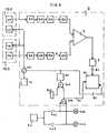
- FIG. 3also shows the sets 12G and 12D, the first comprising the transmitter 1G and the detector 2G, and the second, the transmitter 1D and the detector 2D.
- the two transmittersare controlled in parallel by a pulse generator 10, the pulses supplied by this generator being transmitted to them via a blocking gate 101 whose role will be defined below.
- the transmitterstherefore emit infrared radiation in the form of pulses whose frequency, of the order of 2 to 10 kHz, amplitude and duration, of the order of 15 ps , are defined by the setting of generator 10.
- the radiation reflected by the road surfaceis substantially of the same amplitude.
- the radiation reflected on the detector 2Gis of greater amplitude than that reflected on the detector 2D.
- FIG. 3we will now refer to FIG. 3 to describe the circuits associated with the system and contained in the device 2.
- the 2G and 2D detectorsare respectively connected at output to the 3G ef3D filters, these filters being tuned to let pass only the impulse signals emitted by the transmitters.
- the 3G and 3D filtersare themselves connected to the 5G and 5D rectifiers via 4G and 4D preamplifiers, respectively.
- One of the aforementioned rectifiersin this case the 5G rectifier, lets through only the positive half-waves of the pulsed infrared signal; the other rectifier; in this case the 5D rectifier, lets through only the negative half-waves of the pulsed infrared signal.
- the rectifiers 5G and 5D signalsof positive and negative polarity respectively, the amplitudes of which are substantially of the same value when the vehicle is traveling correctly.
- the signals from the rectifiers 5G and 5Dare transferred to the inputs of a comparison circuit 7, via the triggers 6G and 6D respectively.
- the role of these triggersis to allow the signals to pass only after a certain number of pulses, which avoids untimely operation of the system when the one of the detectors "sees" clearer surfaces for a relatively short time, for example when the vehicle passes over broken glass, puddles of water, etc.
- the comparison circuit 7is designed so that it provides a signal of positive polarity when the 2G detector intercepts a lighter band than the road surface, and a signal of negative polarity when the 2D detector intercepts a lighter band than the road surface.
- the output signal of the comparison circuitis of course zero when the vehicle is traveling correctly.
- the comparison circuit 7is coupled at the output to a holding circuit 8.
- the holding circuit 8makes it possible to obtain a signal of positive polarity or of negative polarity, but the duration of which is fixed and can be adjustable.
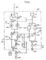
- This signal 81is transferred to the input of a use circuit 20 which includes the aforementioned visual and audible warning means, and which is shown in detail in FIG. 4.
- the pulse generator 10is associated with a blocking door 101. This door has the role of prohibiting the operation of the transmitters, and therefore of the system, under certain conditions.
- the flashing unit 40 of the vehicleis shown in FIG. 3, with the flashing switches 401 and 403 and the flashing lights 402 and 404.
- the signals from the flashing unitare transferred to the input of a holding circuit 30 via OR gates 303 and 301, this holding circuit transforming them into a fixed-duration signal used to block the door 101 associated with the pulse generator 10. It will be noted that the signals from the flashing unit are also transferred to the use circuit 20 through the conductor 41.
- FIG. 3shows a contactor 302 which is a manual contactor of the push button type for example.
- the contactor 302is used to temporarily stop the system when the vehicle, traveling correctly, must pass certain signaling marks on the ground (arrows, etc.). The driver then operates this contactor, which results in the sending of a pulse to the input of the holding circuit 30, via the OR gate 301, this holding circuit transforming this pulse into a duration signal. fixed which blocks the door 101 associated with the pulse generator 10. It will be noted that the signal at the output of the circuit 30 is transferred to the use circuit 20 via the conductor 61.
- the use circuit 20is represented in FIG. 4. As said previously, it receives at 81 a signal of positive polarity or a signal of negative polarity, these signals being of fixed duration, when the 2G detector or the 2D detector intercepts a lighter strip than the road surface. It will be noted that the duration of the above-mentioned signals is only fixed if there is a temporary crossing of a clear band. Of course, if the vehicle is traveling continuously so that one of the detectors permanently "sees" a clear strip, the signals considered will be continuously supplied to the operating circuit.
- the signal received at 81is transferred to the input of a light indicator circuit 21 which constitutes the light warning means of the system.
- the circuit 21has two branches in parallel. One of the branches comprises in series a modulation transistor 214 and a light emitting diode 216.
- the other branchcomprises in series a reverse bias diode 211, a polarity reverser 212, a modulation transistor 213 and a emitting diode of light 215.
- the first branchis conducting for positive polarity signals and the second branch is conducting for negative polarity signals, the role of the diode 211 being to block the positive polarity signals and the polarity of the signals it transmits being inverted in the inverter 212.
- the light-emitting diode 215 or 216there is therefore at the input of the light-emitting diode 215 or 216, in the case where the right 2D detector or the left 2G detector intercepts a light band, a signal of positive polarity which is modulated at the frequency of the signals supplied by the generator 24, which is coupled to the modulation transistors 213 and 214.
- the light-emitting diode 215will therefore flash if the right 2D detector intercepts a ban clear, and the light emitting diode 216 will flash if the left detector 2G intercepts a clear band. The driver is thus visually informed of the direction in which he must operate the straightening of the vehicle trajectory.
- the usage circuit 20also includes an audible indicator circuit 22 which constitutes the audible warning means of the system.
- the circuit 22also has two branches in parallel. One of the branches has the door ET 221; it is on for signals from the light indicator circuit 21 when a manual switch 23 is placed in the "alarm" position A by the driver. When one or other of the 2G and 2D detectors intercepts a clear band, the signal at the output of the light indicator circuit 21 is therefore transferred, if the switch 23 is in the "alarm" position, without attenuation at the sound module 226 , via the AND gate then passing and the OR gate 225.
- the aforementioned signalis, still in the case where the switch 23 is in the "alarm" position, also transferred to the relay 228 via the gate ET 227 then passing.
- the contacts of this relaycan be used at the discretion of the driver for the control of additional audible or light alarms, for example.
- the switch 23has a second position V or standby position which allows a driver who is not at risk of drowsiness to control the operation of the system without being hindered by the signals transmitted through the sound module 226.
- the switch 23When the switch 23 is in the "standby" position, the AND gate 222 is on, and the signals from the light indicator circuit 21 are transferred to the sound module 226, via this AND gate 222, from the OR gate 223, from potentiometer 224 and of OR gate 225, potentiometer 224 making it possible to adjust the intensity of the signals transmitted via the sound module 226.
- the OR gate 223receives, via the driver 41, the signals coming from the vehicle flashing unit (40, FIG. 3), when the driver activates one or other of the flashing lights of this vehicle.
- the OR gate 223receives, via the driver 41, the signals coming from the vehicle flashing unit (40, FIG. 3), when the driver activates one or other of the flashing lights of this vehicle.
- the operating circuit 20includes a generator 24 of modulation signals, the frequency of these being of the order of 3 Hz.
- the presence of this generator of modulation signalsis used to advantage in this system for controlling a circuit 25 for visual operation control.
- Circuit 25has two branches. The first branch consists of a pulse converter 251 and an AND gate 253 which is on when the switch 23 is in the "standby" position V.
- the second branchconsists of a pulse converter 252 and an AND gate 254 which is on when the switch 23 is in the "alarm” position A.
- the signals from the modulation signal generator 24are therefore transferred to the indicator light 257, via the OR gate 255 , the blocking door 256 (the conditions for blocking it are defined below), and one or other of the branches 251-253 and 252-254.
- the converter 251transforms the rectangular pulses with positive and negative waves of the same duration, which come from the generator 24, into pulses with long positive waves and short negative waves. Therefore, when the switch 23 is in the "standby” position, the indicator light 257 will be powered so that it will flash, but with extremely short extinction times.
- the converter 252transforms the pulses from the generator 24 into short positive wave and long negative wave pulses. Therefore, when the switch 23 is in the "alarm” position, the indicator light 257 will be powered so that it will flash, but with extremely long extinction times.
- the driver of the vehiclewill therefore have a visual operating control means capable of permanently informing him of the position in which the switch 23 is located.
- the use circuit 20is coupled at the output of the holding circuit 30 via the conductor 61 ( Figure 3).
- the signal from the holding circuit 30is transferred to the blocking input of the door 256. Therefore, when the driver of the vehicle temporarily stops the system, or switches on one of the flashing lights, the operation of the warning light 257 is temporarily arrested.
- the transmitter-detector assembliescan be arranged, either transversely to the front of the vehicle as shown, or longitudinally with respect to the vehicle, or vertically depending on the application.
- the vehiclemay in fact not be a road vehicle, but an airplane, a boat, a train, a barge in a narrow lock, in a parking lot or a parking lane, the system then involving a light color marking possibly coded.
Landscapes
- Physics & Mathematics (AREA)
- Engineering & Computer Science (AREA)
- Electromagnetism (AREA)
- General Physics & Mathematics (AREA)
- Radar, Positioning & Navigation (AREA)
- Remote Sensing (AREA)
- Computer Networks & Wireless Communication (AREA)
- Aviation & Aerospace Engineering (AREA)
- Automation & Control Theory (AREA)
- Emergency Alarm Devices (AREA)
- Traffic Control Systems (AREA)
Description
Translated fromFrenchLa présente invention concerne, d'une manière générale, un système indicateur de changement de trajectoire d'un véhicule; elle a plus particulièrement trait à un système signalant par voie sonore et éventuellement lumineuse, au conducteur d'un véhicule, qu'il doit redresser la trajectoire de ce véhicule pour le maintenir en dehors d'au moins une limite du trajet qu'il doit suivre, cette limite étant matérialisée, par exemple, par une bande de revêtement de teinte plus claire que le revêtement de la route s'il s'agit d'un véhicule routier.The present invention relates, in general, to a vehicle path change indicator system; it relates more particularly to a system signaling by sound and possibly light, to the driver of a vehicle, that he must straighten the trajectory of this vehicle to keep it outside at least one limit of the journey that he must follow, this limit being materialized, for example, by a strip of coating of lighter shade than the coating of the road if it is a road vehicle.
On connaît nombre de dispositifs s'apparentant plus ou moins au système conforme à l'invention. Ce sont généralement des dispositifs de guidage utilisés, soit pour la construction de routes, (voir par exemple les documents FR-A-1 464 063 et FR-A-1 591 195 ou les brevets US-A-2 520 680 et US-A-3 298 352), soit pour le guidage entièrement automatique de véhicules (voir par exemple les brevets US-A-2 570 583, US-A-3 229 660 et le document FR-A-2 357 946), et faisant appel, pour certains de ces derniers brevets, à un marquage particulier du réseau routier, éventuellement par un produit radioactif.A number of devices are known which are more or less akin to the system according to the invention. These are generally guide devices used, either for road construction, (see for example the documents FR-A-1 464 063 and FR-A-1 591 195 or the patents US-A-2 520 680 and US- A-3,298,352), or for the fully automatic guidance of vehicles (see for example the patents US-A-2,570,583, US-A-3,229,660 and the document FR-A-2,357,946), and call, for some of these latter patents, to a specific marking of the road network, possibly with a radioactive product.
D'une manière générale, les systèmes connus de guidage automatique utilisent des moyens récepteurs d'ondes électromagnétiques montés à bord du véhicule, éventuellement des moyens générateurs d'ondes électromagnétiques généralement montés à bord du véhicule, et des moyens matérialisant le trajet que doit suivre ce véhicule.In general, known automatic guidance systems use means for receiving electromagnetic waves mounted on board the vehicle, optionally means generating electromagnetic waves generally mounted on board the vehicle, and means materializing the path which must follow. this vehicle.
Le document FR-A-2 271 611 décrit, par exemple, un système de guidage automatique à générateur(s) optique(s) utilisant obligatoirement des répondeurs réflecteurs ou catadioptres pour matérialiser une voie de communication. L'intensité varie selon une loi gaussienne dans le faisceau optique émis, en fonction de la coordonnée Z perpendiculaire à l'axe de la voie. Selon la position occupée par le véhicule sur la coordonnée Z, les signaux reçus ont une amplitude plus ou moins élevée.The document FR-A-2 271 611 describes, for example, an automatic guidance system with optical generator (s) necessarily using reflector or reflector responders to materialize a communication channel. The intensity varies according to a Gaussian law in the optical beam emitted, as a function of the Z coordinate perpendicular to the axis of the track. Depending on the position occupied by the vehicle on the Z coordinate, the signals received have a greater or lesser amplitude.
Le système de guidage automatique décrit dans le brevet US-A-2 424 288 est à deux générateurs de lumière utilisant obligatoirement une bande de guidage centrale pour matérialiser la voie. Tout déséquilibre entre les signaux réfléchis sur deux cellules réceptrices par la bande entraîne le redressement automatique du véhicule.The automatic guidance system described in patent US-A-2 424 288 is with two light generators necessarily using a central guide strip to materialize the track. Any imbalance between the signals reflected on two receiver cells by the strip leads to the automatic recovery of the vehicle.
Dans le brevet US-A-2 074 251, on décrit un système de guidage automatique à une seule source émettrice utilisant obligatoirement une bande de guidage parfaitement nette pour réfléchir la lumière qu'elle reçoit vers l'un ou l'autre de deux groupes droit ou gauche de cellules selon la position du véhicule par rapport à la bande, et redresser en conséquence de véhicule.In patent US Pat. No. 2,074,251, an automatic guidance system with a single emitting source is described, necessarily using a perfectly sharp guide strip to reflect the light it receives towards one or the other of two groups. right or left cells depending on the position of the vehicle relative to the strip, and straighten the vehicle accordingly.
Dans le brevet GB-A-1 241 722, on décrit un système de mise en place de camions en des emplacements de chargement prédéterminés, utilisant des bandes cataphotes au sol en nombre et positions prédéterminés, et un double système de comptage à deux détecteurs.In patent GB-A-1 241 722, a system for placing trucks at predetermined loading locations is described, using cataphotic strips on the ground in predetermined number and positions, and a double counting system with two detectors.
Dans le brevet US-A-3 708 688, on décrit un système de guidage automatique à deux groupes de mêmes cellules photodétectrices en même nombre, l'un orienté très précisément pour intercepter une bande de voie coupant perpendiculairement la bande interrompue matérialisant la route, avec la cellule centrale dirigée sur cette bande, l'autre uniquement de compensation pour tenir compte des modifications de réflectivité de la route.In patent US-A-3,708,688, an automatic guidance system is described with two groups of the same photodetector cells in the same number, one oriented very precisely to intercept a strip of track perpendicularly cutting the interrupted strip materializing the road, with the central cell directed on this strip, the other only compensation to take account of the changes in reflectivity of the road.
On trouve également dans le document FR-A-2 406 245 la description d'un système de correction de changement de trajectoire d'un véhicule par rapport à une voie de déplacement, l'axe central de cette voie étant matérialisé par une bande réfléchissante centrale. Deux groupes émetteur- récepteur sont placés sur le véhicule transversalement à l'axe de la voie, et fournissent des signaux de tension de sortie de signe opposé. La distance qui sépare les deux groupes et la largeur des faisceaux d'émission-réception sont déterminés par rapport à la largeur de la bande réfléchissante pour obtenir un signal d'asservissement lorsque l'axe du détecteur que constituent les deux groupes ne coïncide pas avec l'axe de la voie réfléchissante.Document FR-A-2 406 245 also describes a system for correcting the change of trajectory of a vehicle relative to a travel lane, the central axis of this lane being materialized by a reflective strip. central. Two transmitter-receiver groups are placed on the vehicle transverse to the center line of the track, and provide output voltage signals of opposite sign. The distance between the two groups and the width of the transmit-receive beams are determined relative to the width of the reflective strip to obtain a servo signal when the axis of the detector constituted by the two groups does not coincide with the axis of the reflecting path.
Enfin, dans le brevet US-A-3172 496, il s'agit d'un système de guidage automatique utilisant des moyens de guidage qui peuvent être les deux bandes jalonnant la voie, et une lentille de formation d'une image de la route; derrière tourne un dispositif d'exploration associé à des dispositifs photo-électriques.Finally, in US-A-3172 496, it is an automatic guidance system using guidance means which can be the two strips marking out the track, and a lens for forming an image of the road. ; behind it turns an exploration device associated with photoelectric devices.
Les systèmes que l'on vient d'évoquer sont relativement complexes et il est très important de remarquer qu'ils utilisent tous, à titre d'élément actif en permanence, une ou des bandes matérialisant la voie, ce qui nécessite, pour la plupart d'entre eux, une orientation très précise des dispositifs détecteurs et éventuellement émetteurs, et, pour le système décrit dans le brevet US-A-3 172 496, une exploration permanente d'une image complète de la route.The systems that we have just mentioned are relatively complex and it is very important to note that they all use, as permanently active element, one or more bands materializing the track, which requires, for the most part of them, a very precise orientation of the detector and possibly transmitter devices, and, for the system described in US-A-3,172,496, a permanent exploration of a complete picture of the road.
On peut donc dire en résumé que les systèmes connus considérés dans leur ensemble présentent les inconvénients suivants:
- - ils peuvent exiger la modification du réseau routier existant,
- - ils peuvent utiliser des produits émettant des radiations ionisantes dangereuses,
- - le fonctionnement de leurs circuits peut être brouillé par des interférences provoquées par des ondes en provenance d'autres sources (flaque d'eau par exemple),
- - comme on l'a dit précédemment, ils utilisent, à titre d'élément actif en permanence, une ou des bandes matérialisant la voie,
- - ayant pour objectif un guidage entièrement automatique du véhicule, ils doivent être parfaitement fiables en dépit de la complexité des circuits,
- - étant relativement complexes, ils sont d'un prix de revient élevé.
- - they may require the modification of the existing road network,
- - they can use products emitting dangerous ionizing radiation,
- - the operation of their circuits may be interfered with by interference caused by waves from other sources (puddle for example),
- - as mentioned above, they use, as a permanently active element, one or more bands materializing the track,
- - aiming at fully automatic vehicle guidance, they must be perfectly reliable despite the complexity of the circuits,
- - being relatively complex, they are of a high cost price.
L'invention a pour objectif la réalisation d'un système indicateur de changement de trajectoire d'un véhicule qui n'exige pas la modification du réseau routier existant, qui n'utilise pas de produits émettant des radiations ionisantes dangereuses, dont le fonctionnement est fiable même en présence de différences de teinte dans le revêtement routier, ce dispositif étant simple et, par suite, d'un prix de revient modeste.The object of the invention is the production of a trajectory change indicator system of a vehicle which does not require modification of the existing road network, which does not use products emitting dangerous ionizing radiation, whose operation is reliable even in the presence of differences in color in the road surface, this device being simple and, consequently, of a modest cost price.
Pour réaliser l'objectif mentionné ci-dessus, l'invention propose un système indicateur de changement de trajectoire, notamment d'un véhicule, par rapport à une voie de déplacement, comportant deux ensembles émetteur-détecteur d'ondes électromagnétiques fixés sur le véhicule à distance l'un de l'autre, sur un axe transversal à l'axe de la voie définissant la trajectoire, cette voie étant matérialisée par un revêtement contrastant avec les parties latérales qui la bordent, l'une au moins de ces parties pouvant être une bande réflectrice des ondes électromagnétiques précitées, et les deux détecteurs des ensembles étant couplés à des moyens de comparaison dont le signal de sortie est nul lorsque le véhicule circule correctement entre les parties latérales bordant la voie, caractérisé en ce qu'il comporte un générateur couplé aux émetteurs des ensembles, et conçu pour que les ondes électromagnétiques soient émises et détectées sous forme d'impulsions successives de signaux alternatifs, ces impulsions ayant une fréquence, une amplitude et une durée déterminées, en ce que les deux détecteurs sont couplés aux moyens de comparaison par l'intermédiaire, respectivement de deux redresseurs dont l'un laisse passer les alternances négatives des signaux et l'autre, les alternances positives, chaque détecteur étant en série avec, entre autres, un déclencheur réglé pour ne transmettre un signal aux moyens de comparaison qu'au terme d'un certain nombre d'impulsions reçues et en ce que des moyens d'avertissement lumineux et sonores sont associés auxdits moyens de comparaison, lesdits moyens d'avertissement étant rendus actifs lorsque, le véhicule déviant de sa trajectoire, l'un desdits ensembles émetteur-détecteur intercepte la ou une bande latérale bordant la voie.To achieve the objective mentioned above, the invention proposes a system for indicating the change of trajectory, in particular of a vehicle, relative to a travel path, comprising two emitter-detector assemblies of electromagnetic waves fixed to the vehicle. at a distance from each other, on an axis transverse to the axis of the track defining the trajectory, this track being materialized by a coating contrasting with the lateral parts which border it, at least one of these parts being able to be a reflective strip of the aforementioned electromagnetic waves, and the two detectors of the assemblies being coupled to comparison means whose output signal is zero when the vehicle travels correctly between the lateral parts bordering the track, characterized in that it comprises a generator coupled to the transmitters of the assemblies, and designed so that the electromagnetic waves are emitted and detected in the form of successive pulses of alternating signals, these pulses having a determined frequency, amplitude and duration, in that the two detectors are coupled to the comparison means via, respectively, two rectifiers, one of which lets negative alternations of the signals pass and the other, the positive half-waves, each detector being in series with, among other things, a trigger set to transmit a signal to the comparison means only after a certain number of pulses received and in that light and sound warning means are associated with said comparison means, said warning means being made active when, the vehicle deviating from its trajectory, one of said transmitter-detector assemblies intercepts the or a side strip bordering the track.
La suite de la description se réfère aux dessins annexés qui représentent:
- - figure 1, une vue schématique en plan d'un véhicule équipé du système conforme à l'invention.
- - figures 2A et 2B, à titre d'exemple, une illustration schématique des ensembles émetteur-détecteur portés par le véhicule, lorsque la trajectoire de ce dernier est correcte (figure 2A), lorsque cette trajectoire est déviée (figure 2B),
- - figure 3, un schéma des circuits du dispositif, associés aux ensembles émetteur-détecteur,
- - figure 4, le schéma du circuit d'utilisation 20 de la figure 3.
- - Figure 1, a schematic plan view of a vehicle equipped with the system according to the invention.
- FIGS. 2A and 2B, by way of example, a schematic illustration of the transmitter-detector assemblies carried by the vehicle, when the trajectory of the latter is correct (FIG. 2A), when this trajectory is deviated (FIG. 2B),
- FIG. 3, a diagram of the circuits of the device, associated with the emitter-detector assemblies,
- - Figure 4, the diagram of the
use circuit 20 of Figure 3.
On a représenté très schématiquement figure 1 un véhicule VV circulant dans le sens de la flèche AA. On supposera que ce véhicule est un véhicule routier, la voie qu'il doit suivre étant limitée par une bande centrale interrompue C, à sa gauche dans l'exemple représenté, et éventuellement par une bande latérale L à sa droite.Very schematically shown in Figure 1 a vehicle VV traveling in the direction of arrow AA. It will be assumed that this vehicle is a road vehicle, the lane which it must follow being limited by an interrupted central strip C, to its left in the example shown, and possibly by a lateral strip L to its right.
A l'avant de ce véhicule, par exemple sous le pare-choc avant, sont fixés deux ensembles, 12G à gauche et 12D à droite, chacun des ces ensembles se composant d'un émetteur et d'un détecteur d'ondes électromagnétiques contenues dans le spectre infrarouge. A bord du véhicule, devant le conducteur, est placé le dispositif 2 qui est relié aux émetteurs et aux détecteurs des ensembles 12G et 12D et qui contient les circuits électroniques du système.At the front of this vehicle, for example under the front bumper, are fixed two assemblies, 12G on the left and 12D on the right, each of these assemblies consisting of a transmitter and a detector of contained electromagnetic waves in the infrared spectrum. On board the vehicle, in front of the driver, is placed the
On a illustré, également très schématiquement, figures 2A et 2B, le véhicule VV avec les ensembles précédemment cités et montés aux angles extérieurs, avant gauche et avant droit, du véhicule, ces ensembles comportant respectivement un émetteur (1G, 1D) et un détecteur (2G, 2D), et le véhicule illustré figure 2B franchissant la bande centrale interrompue C qui limite un côté de la voie. Les axes des émetteurs et des détecteurs sont dirigés perpendiculairement sur le sol.Also illustrated very diagrammatically, FIGS. 2A and 2B, the vehicle VV with the above-mentioned assemblies and mounted at the exterior angles, front left and front right, of the vehicle, these assemblies comprising respectively a transmitter (1G, 1D) and a detector (2G, 2D), and the vehicle illustrated in FIG. 2B crossing the interrupted central strip C which limits one side of the track. The axes of the transmitters and detectors are directed perpendicularly to the ground.
On a également illustré figure 3 les ensembles 12G et 12D, le premier comportant l'émetteur 1G et le détecteur 2G, et le second, l'émetteur 1D et le détecteur 2D. Les deux émetteurs sont commandés en parallèle par un générateur d'impulsions 10, les impulsions fournies par ce générateur leur étant transmises par l'intermédiaire d'une porte de blocage 101 dont le rôle sera défini ci-après. Lorsque la porte 101 n'est pas bloquée, les émetteurs émettent donc des radiations infrarouges sous forme d'impulsions dont la fréquence, de l'ordre de 2 à 10 kHz, l'amplitude et la durée, de l'ordre de 15 ps, sont définies par le réglage du générateur 10.FIG. 3 also shows the sets 12G and 12D, the first comprising the transmitter 1G and the
Lorsque le véhicule circule correctement, comme illustré figure 2A, les radiations réfléchies par le revêtement routier sont sensiblement de même amplitude. Par contre, lorsque le véhicule franchit la bande centrale interrompue, comme illustré figure 2B, les radiations réfléchies sur le détecteur 2G sont de plus grande amplitude que celles réfléchies sur le détecteur 2D. On remarquera à ce propos qu'il suffit que l'un des détecteurs «voit», pendant un temps suffisamment long comme on le verra par la suite, une bande de teinte suffisamment contrastée ou différente quant à sa nature par rapport au revêtement routier, pour que le système devienne actif. Ce système peut donc être utilisé même sur les routes ne comportant pas de bandes de signalisation latérales, et fonctionne même lorsque le véhicule franchit une bande d'herbe jalonnant la route et qui se trouve à distance différente des détecteurs par rapport au revêtement routier.When the vehicle is traveling correctly, as illustrated in FIG. 2A, the radiation reflected by the road surface is substantially of the same amplitude. On the other hand, when the vehicle crosses the interrupted central strip, as illustrated in FIG. 2B, the radiation reflected on the
On se reportera maintenant à la figure 3 pour décrire les circuits associés au système et contenus dans le dispositif 2.We will now refer to FIG. 3 to describe the circuits associated with the system and contained in the
Les détecteurs 2G et 2D sont respectivement raccordés en sortie aux filtres 3G ef3D, ces filtres étant accordés pour ne laisser passer que les signaux impulsionnels émis par les émetteurs. Les filtres 3G et 3D sont eux-mêmes raccordés aux redresseurs 5G et 5D par l'intermédiaire de préamplificateurs 4G et 4D, respectivement. L'un des redresseurs précités, en l'occurence le redresseur 5G, ne laisse passer que les alternances positives du signal infrarouge impulsionnel; l'autre redresseur; en l'occurence le redresseur 5D, ne laisse passer que les alternances négatives du signal infrarouge impulsionnel. On obtient donc en sortie des redresseurs 5G et 5D des signaux de polarité positive et négative respectivement, dont les amplitudes sont sensiblement de même valeur lorsque le véhicule circule correctement.The 2G and 2D detectors are respectively connected at output to the 3G ef3D filters, these filters being tuned to let pass only the impulse signals emitted by the transmitters. The 3G and 3D filters are themselves connected to the 5G and 5D rectifiers via 4G and 4D preamplifiers, respectively. One of the aforementioned rectifiers, in this case the 5G rectifier, lets through only the positive half-waves of the pulsed infrared signal; the other rectifier; in this case the 5D rectifier, lets through only the negative half-waves of the pulsed infrared signal. We therefore obtain at the output of the rectifiers 5G and 5D signals of positive and negative polarity respectively, the amplitudes of which are substantially of the same value when the vehicle is traveling correctly.
Les signaux issus des redresseurs 5G et 5D sont transférés sur les entrées d'un circuit de comparaison 7, par l'intermédiaire des déclencheurs 6G et 6D respectivement. Le rôle de ces déclencheurs, qui peuvent être constitués simplement par une résistance série et un condensateur parallèle, est de ne laisser passer les signaux qu'au terme d'un certain nombre d'impulsions, ce qui évite le fonctionnement intempestif du système lorsque l'un des détecteurs «voit» des surfaces plus claires pendant un temps relativement court, par exemple lorsque le véhicule passe sur des débris de verre, des flaques d'eau, etc...The signals from the rectifiers 5G and 5D are transferred to the inputs of a
Le circuit de comparaison 7 est conçu de telle sorte qu'il fournit un signal de polarité positive lorsque le détecteur 2G intercepte une bande plus claire que le revêtement routier, et un signal de polarité négative lorsque le détecteur 2D intercepte une bande plus claire que le revêtement routier. Le signal de sortie du circuit de comparaison est bien entendu nul lorsque le véhicule circule correctement.The
Le circuit de comparaison 7 est couplé en sortie à un circuit de maintien 8. On doit tenir compte en effet de la largeur relativement faible des bandes claires appliquées sur le revêtement routier et de la vitesse variable d'un véhicule qui font que le fonctionnement des détecteurs est de plus ou moins longue durée. Le circuit de maintien 8 permet d'obtenir un signal de polarité positive ou de polarité négative, mais dont la durée est fixe et peut être réglable. Ce signal 81 est transféré à l'entrée d'un circuit d'utilisation 20 qui comporte les moyens d'avertissement visuels et sonores précédemment mentionnés, et qui est représenté en détails figure 4.The
On a dit précédemment que le générateur d'impulsions 10 est associé à une porte de blocage 101. Cette porte a pour rôle d'interdire le fonctionnement des émetteurs, et donc du système, dans certaines conditions.It was said previously that the
On a représenté figure 3 la centrale clignotante 40 du véhicule, avec les contacteurs de clignotant 401 et 403 et les feux clignotants 402 et 404. Lorsque le conducteur, parce qu'il doit tourner ou dépasser le véhicule qui le précède, met en marche l'un ou l'autre des feux clignotants 402 ou 404 en manoeuvrant l'un ou l'autre des contacteurs 401 ou 403, les signaux de la centrale clignotante sont transférés à l'entrée d'un circuit de maintien 30 par l'intermédiaire des portes OU 303 et 301, ce circuit de maintien les transformant en signal de durée fixe utilisé pour bloquer la porte 101 associée au générateur d'impulsions 10. On notera que les signaux issus de la centrale clignotante sont également transférés au circuit d'utilisation 20 par l'intermédiaire du conducteur 41.The
On a représenté figure 3 un contacteur 302 qui est un contacteur manuel du type bouton-poussoir par exemple. Le contacteur 302 est utilisé pour arrêter temporairement le système lorsque le véhicule, circulant correctement, doit franchir certaines marques de signalisation au sol (flèches, etc...). Le conducteur manoeuvre alors ce contacteur, ce qui se traduit par l'envoi d'une impulsion à l'entrée du circuit de maintien 30, par l'intermédiaire de la porte OU 301, ce circuit de maintien transformant cette impulsion en signal de durée fixe qui vient bloquer la porte 101 associée au générateur d'impulsions 10. On notera que le signal en sortie du circuit 30 est transféré au circuit d'utilisation 20 par l'intermédiaire du conducteur 61.FIG. 3 shows a
Le circuit d'utilisation 20 est représenté figure 4. Comme on l'a dit précédemment, il reçoit en 81 un signal de polarité positive ou un signal de polarité négative, ces signaux étant de durée fixe, lorsque le détecteur 2G ou le détecteur 2D intercepte une bande plus claire que le revêtement routier. On notera que la durée des signaux précités n'est fixe que s'il y a franchissement temporaire d'une bande claire. Bien entendu, si le véhicule circule en permanence de telle sorte que l'un des détecteurs «voit» en permanence une bande claire, les signaux considérés seront fournis en permanence au circuit d'utilisation.The
Le signal reçu en 81 est transféré à l'entrée d'un circuit d'indicateurs lumineux 21 qui constitue les moyens d'avertissement lumineux du système. Le circuit 21 comporte deux branches en parallèle. L'une des branches comporte en série un transistor de modulation 214 et une diode émettrice de lumière 216. L'autre branche comporte en série une diode en polarisation inverse 211, un inverseur de polarité 212, un transistor de modulation 213 et une diode émettrice de lumière 215. La première branche est passante pour les signaux de polarité positive et la seconde branche est passante pour les signaux de polarité négative, le rôle de la diode 211 étant de bloquer les signaux de polarité positive et la polarité des signaux qu'elle transmet étant inversée dans l'inverseur 212. On a donc à l'entrée de la diode émettrice de lumière 215 ou 216, dans le cas où le détecteur droit 2D ou le détecteur gauche 2G intercepte une bande claire, un signal de polarité positive qui est modulé à la fréquence des signaux fournis par le générateur 24, lequel est couplé aux transistors de modulation 213 et 214. La diode émettrice de lumière 215 clignotera donc si le détecteur de droite 2D intercepte une bande claire, et la diode émettrice de lumière 216 clignotera si le détecteur de gauche 2G intercepte une bande claire. Le conducteur est ainsi informé visuellement du sens dans lequel il doit opérer le redressement de la trajectoire du véhicule.The signal received at 81 is transferred to the input of a light indicator circuit 21 which constitutes the light warning means of the system. The circuit 21 has two branches in parallel. One of the branches comprises in series a
Le circuit d'utilisation 20 comporte également un circuit d'indicateur sonore 22 qui constitue les moyens d'avertissement sonores du système. Le circuit 22 comporte également deux branches en parallèle. L'une des branches comporte la porte ET 221; elle est passante pour les signaux issus du circuit d'indicateurs lumineux 21 lorsqu'un commutateur manuel 23 est placé sur la position «alarme» A par le conducteur. Lorsque l'un ou l'autre des détecteurs 2G et 2D intercepte une bande claire, le signal en sortie du circuit d'indicateurs lumineux 21 est donc transféré, si le commutateur 23 est en position «alarme», sans atténuation au module son 226, par l'intermédiaire de la porte ET alors passante et de la porte OU 225. Le signal précité est, toujours dans le cas où le commutateur 23 est en position «alarme», transféré également au relais 228 par l'intermédiaire de la porte ET 227 alors passante. Les contacts de ce relais peuvent être utilisés au gré du conducteur pour la commande d'avertisseurs supplémentaires sonores ou lumineux, par exemple.The
Le commutateur 23 comporte une deuxième position V ou position de veille qui permet à un conducteur ne risquant pas la somnolence de contrôler le fonctionnement du système sans pour autant être gêné par les signaux émis par l'intermédiaire du module son 226. Lorsque le commutateur 23 est sur la position «veille», la porte ET 222 est passante, et les signaux issus du circuit d'indicateurs lumineux 21 sont transférés au module son 226, par l'intermédiaire de cette porte ET 222, de la porte OU 223, du potentiomètre 224 et de la porte OU 225, le potentiomètre 224 permettant de régler l'intensité des signaux émis par l'intermédiaire du module son 226.The
On remarquera que la porte OU 223 reçoit, par l'intermédiaire du conducteur 41, les signaux issus de la centrale clignotante du véhicule (40, figure 3), lorsque le conducteur met en marche l'un ou l'autre des feux clignotants de ce véhicule. On a donc mis à profit dans ce système la présence d'un circuit d'indicateur sonore pour donner au conducteur du véhicule une indication sonore de la mise en marche de l'un ou l'autre des feux clignotants.It will be noted that the
Comme on l'a dit précédemment, le circuit d'utilisation 20 comporte un générateur 24 de signaux de modulation, la fréquence de ces derniers étant de l'ordre de 3 Hz. La présence de ce générateur de signaux de modulation est mise à profit dans ce système pour commander un circuit 25 de contrôle visuel de fonctionnement. Le circuit 25 comporte deux branches. La première branche se compose d'un convertisseur d'impulsions 251 et d'une porte ET 253 qui est passante lorsque le commutateur 23 est sur la position «veille» V. La deuxième branche se compose d'un convertis- seurd'impulsions 252 et d'une porte ET 254 qui est passante lorsque le commutateur 23 est dans la position «alarme» A. Les signaux issus du générateur de signaux de modulation 24 sont donc transférés au témoin lumineux 257, par l'intermédiaire de la porte OU 255, de la porte de blocage 256 (les conditions de son blocage sont définies ci-après), et de l'une ou l'autre des branches 251-253 et 252-254.As mentioned above, the operating
Comme on l'a illustré figure 4, le convertisseur 251 transforme les impulsions rectangulaires à ondes positives et négatives de même durée, qui sont issues du générateur 24, en impulsions à ondes positives longues et ondes négatives courtes. Donc, lorsque le commutateur 23 sera sur la position «veille», le témoin lumineux 257 sera alimenté de telle sorte qu'il clignotera, mais avec des temps d'extinction extrêmement courts. Par contre, le convertisseur 252 transforme les impulsions issues du générateur 24 en impulsions à ondes positives courtes et ondes négatives longues. Donc, lorsque le commutateur 23 sera dans la position «alarme», le témoin lumineux 257 sera alimenté de telle sorte qu'il clignotera, mais avec des temps d'extinction extrêmement longs. Le conducteur du véhicule disposera donc d'un moyen de contrôle visuel de fonctionnement pouvant l'informer en permanence de la position dans laquelle se trouve le commutateur 23.As illustrated in FIG. 4, the
Enfin, on a dit précédemment que le circuit d'utilisation 20 est couplé en sortie du circuit de maintien 30 par l'intermédiaire du conducteur 61 (figure 3). Le signal du circuit de maintien 30 est transféré sur l'entrée de blocage de la porte 256. Donc, lorsque le conducteur du véhicule arrête temporairement le système, ou met en marche l'un des feux clignotants, le fonctionnement du témoin lumineux 257 est temporairement arrêté.Finally, it was said previously that the
Il est bien entendu que la description qui précède a été faite à titre d'exemple non-limitatif, des variantes pouvant être envisagées dans le cadre de l'invention. C'est ainsi que les ensembles émetteur-détecteur peuvent être disposés, soit transversalement à l'avant du véhicule comme il a été représenté, soit longitudinalement par rapport au véhicule, ou verticalement selon l'application. Le véhicule peut en effet ne pas être un véhicule routier, mais un avion, un bateau, un train, une péniche dans une écluse étroite, sur un parking ou une voie de stationnement, le système impliquant alors un marquage de couleur claire éventuellement codé.It is understood that the foregoing description has been given by way of nonlimiting example, variants which may be envisaged within the framework of the invention. Thus the transmitter-detector assemblies can be arranged, either transversely to the front of the vehicle as shown, or longitudinally with respect to the vehicle, or vertically depending on the application. The vehicle may in fact not be a road vehicle, but an airplane, a boat, a train, a barge in a narrow lock, in a parking lot or a parking lane, the system then involving a light color marking possibly coded.
Claims (12)
Priority Applications (2)
| Application Number | Priority Date | Filing Date | Title |
|---|---|---|---|
| EP80401443AEP0049722B1 (en) | 1980-10-09 | 1980-10-09 | Apparatus for indicating trajectory change |
| DE8080401443TDE3071811D1 (en) | 1980-10-09 | 1980-10-09 | Apparatus for indicating trajectory change |
Applications Claiming Priority (1)
| Application Number | Priority Date | Filing Date | Title |
|---|---|---|---|
| EP80401443AEP0049722B1 (en) | 1980-10-09 | 1980-10-09 | Apparatus for indicating trajectory change |
Publications (2)
| Publication Number | Publication Date |
|---|---|
| EP0049722A1 EP0049722A1 (en) | 1982-04-21 |
| EP0049722B1true EP0049722B1 (en) | 1986-10-29 |
Family
ID=8187395
Family Applications (1)
| Application Number | Title | Priority Date | Filing Date |
|---|---|---|---|
| EP80401443AExpiredEP0049722B1 (en) | 1980-10-09 | 1980-10-09 | Apparatus for indicating trajectory change |
Country Status (2)
| Country | Link |
|---|---|
| EP (1) | EP0049722B1 (en) |
| DE (1) | DE3071811D1 (en) |
Cited By (7)
| Publication number | Priority date | Publication date | Assignee | Title |
|---|---|---|---|---|
| US8818042B2 (en) | 2004-04-15 | 2014-08-26 | Magna Electronics Inc. | Driver assistance system for vehicle |
| US8842176B2 (en) | 1996-05-22 | 2014-09-23 | Donnelly Corporation | Automatic vehicle exterior light control |
| US8917169B2 (en) | 1993-02-26 | 2014-12-23 | Magna Electronics Inc. | Vehicular vision system |
| US8993951B2 (en) | 1996-03-25 | 2015-03-31 | Magna Electronics Inc. | Driver assistance system for a vehicle |
| US9171217B2 (en) | 2002-05-03 | 2015-10-27 | Magna Electronics Inc. | Vision system for vehicle |
| US9436880B2 (en) | 1999-08-12 | 2016-09-06 | Magna Electronics Inc. | Vehicle vision system |
| US9440535B2 (en) | 2006-08-11 | 2016-09-13 | Magna Electronics Inc. | Vision system for vehicle |
Families Citing this family (12)
| Publication number | Priority date | Publication date | Assignee | Title |
|---|---|---|---|---|
| DE19507957C1 (en)* | 1995-03-07 | 1996-09-12 | Daimler Benz Ag | Vehicle with optical scanning device for a side lane area |
| GB2317009A (en)* | 1996-09-07 | 1998-03-11 | John Joseph Green | driver sleep warning system |
| AUPO324996A0 (en)* | 1996-10-28 | 1996-11-21 | Cubero, Samuel N. Jr. | Vehicle straying detector and alarm system |
| FR2759647B1 (en)* | 1997-02-17 | 1999-05-07 | Dominique Pecquet | APPARATUS FOR PREVENTING WITH A SOUND SIGNAL THE TIRED OR DISTRACTED MOTOR DRIVER FROM AN UNINTENDED CHANGE IN ITS VEHICLE TRAJECTORY |
| GB2336205B (en)* | 1998-04-08 | 2000-08-23 | Factorgraft Limited | A vehicle telemetry system |
| FR2821963B1 (en)* | 2001-03-08 | 2003-04-25 | Peugeot Citroen Automobiles Sa | DEVICE FOR DETECTING A BEARING SURFACE AND VEHICLE USING SUCH A DEVICE |
| FR2821962B1 (en) | 2001-03-08 | 2003-04-25 | Peugeot Citroen Automobiles Sa | DEVICE FOR DETECTING A BEARING SURFACE AND VEHICLE USING SUCH A DEVICE |
| FR2837604B1 (en)* | 2002-03-21 | 2004-07-02 | Peugeot Citroen Automobiles Sa | ROAD MONITORING METHOD FOR ROAD VEHICLE ADAPTING TO THE CONDITION AND NATURE OF THE COVERING |
| FR2837605B1 (en)* | 2002-03-21 | 2006-04-14 | Peugeot Citroen Automobiles Sa | ROAD SURVEILLANCE MONITORING DEVICE |
| EP1387184A1 (en)* | 2002-07-25 | 2004-02-04 | EM Microelectronic-Marin SA | Lane drifting detection device |
| DE10354290A1 (en)* | 2003-11-20 | 2005-06-02 | Daimlerchrysler Ag | Lane alignment apparatus, selection apparatus and method for detecting the lane of a vehicle |
| DE102006050214A1 (en)* | 2005-11-04 | 2007-05-24 | Continental Teves Ag & Co. Ohg | A method of assisting a driver when driving with a vehicle |
Citations (4)
| Publication number | Priority date | Publication date | Assignee | Title |
|---|---|---|---|---|
| US2424288A (en)* | 1944-03-24 | 1947-07-22 | Victor H Severy | Automatic steering apparatus |
| US3708668A (en)* | 1971-06-01 | 1973-01-02 | J Tilley | Vehicle optical guidance system |
| DE2504112A1 (en)* | 1974-02-01 | 1975-08-07 | Thomson Csf | ARRANGEMENT FOR THE AUTOMATIC GUIDANCE OF VEHICLES |
| FR2406245A1 (en)* | 1977-10-13 | 1979-05-11 | Matra Engins | Automatic guidance for vehicle in transport installation - employs receiver to sense light reflected from emitter via mirror |
- 1980
- 1980-10-09EPEP80401443Apatent/EP0049722B1/ennot_activeExpired
- 1980-10-09DEDE8080401443Tpatent/DE3071811D1/ennot_activeExpired
Patent Citations (4)
| Publication number | Priority date | Publication date | Assignee | Title |
|---|---|---|---|---|
| US2424288A (en)* | 1944-03-24 | 1947-07-22 | Victor H Severy | Automatic steering apparatus |
| US3708668A (en)* | 1971-06-01 | 1973-01-02 | J Tilley | Vehicle optical guidance system |
| DE2504112A1 (en)* | 1974-02-01 | 1975-08-07 | Thomson Csf | ARRANGEMENT FOR THE AUTOMATIC GUIDANCE OF VEHICLES |
| FR2406245A1 (en)* | 1977-10-13 | 1979-05-11 | Matra Engins | Automatic guidance for vehicle in transport installation - employs receiver to sense light reflected from emitter via mirror |
Cited By (11)
| Publication number | Priority date | Publication date | Assignee | Title |
|---|---|---|---|---|
| US8917169B2 (en) | 1993-02-26 | 2014-12-23 | Magna Electronics Inc. | Vehicular vision system |
| US8993951B2 (en) | 1996-03-25 | 2015-03-31 | Magna Electronics Inc. | Driver assistance system for a vehicle |
| US8842176B2 (en) | 1996-05-22 | 2014-09-23 | Donnelly Corporation | Automatic vehicle exterior light control |
| US9436880B2 (en) | 1999-08-12 | 2016-09-06 | Magna Electronics Inc. | Vehicle vision system |
| US9171217B2 (en) | 2002-05-03 | 2015-10-27 | Magna Electronics Inc. | Vision system for vehicle |
| US9555803B2 (en) | 2002-05-03 | 2017-01-31 | Magna Electronics Inc. | Driver assistance system for vehicle |
| US8818042B2 (en) | 2004-04-15 | 2014-08-26 | Magna Electronics Inc. | Driver assistance system for vehicle |
| US9008369B2 (en) | 2004-04-15 | 2015-04-14 | Magna Electronics Inc. | Vision system for vehicle |
| US9191634B2 (en) | 2004-04-15 | 2015-11-17 | Magna Electronics Inc. | Vision system for vehicle |
| US9428192B2 (en) | 2004-04-15 | 2016-08-30 | Magna Electronics Inc. | Vision system for vehicle |
| US9440535B2 (en) | 2006-08-11 | 2016-09-13 | Magna Electronics Inc. | Vision system for vehicle |
Also Published As
| Publication number | Publication date |
|---|---|
| EP0049722A1 (en) | 1982-04-21 |
| DE3071811D1 (en) | 1986-12-04 |
Similar Documents
| Publication | Publication Date | Title |
|---|---|---|
| EP0049722B1 (en) | Apparatus for indicating trajectory change | |
| EP1553429B1 (en) | System and method for detecting the circulation condition in a vehicle | |
| FR2509067A1 (en) | DEVICE FOR GUIDING A VEHICLE, IN PARTICULAR AN AGRICULTURAL TRACTOR, FOLLOWING A PREDETERMINED RECTILINE PATH, AND TARGET FOR THIS DEVICE | |
| EP0057632B1 (en) | Control method for a train with automatic operation | |
| EP0208610A2 (en) | Device for detection of foreign substances through a wall and aid-system for driving vehicles or aircrafts | |
| FR2940000A1 (en) | PERIMETER SAFETY SYSTEM BY ACTIVE ANALYSIS OF THE IMAGE OF A VIDEO CAMERA | |
| FR2539372A1 (en) | MODULATION SYSTEMS FOR RAILWAY CIRCUITS | |
| EP0716317B1 (en) | Device for the detection and location of ground objects | |
| WO1987000326A1 (en) | Signalling device for warning that a living being is going to cross a traffic road | |
| FR2578797A1 (en) | AUTOMOTIVE DRIVING ASSISTANCE SYSTEM. | |
| EP0050549A1 (en) | Inviolable barrier for the protection against intrusions | |
| FR2622034A1 (en) | Audible warning-decelerator device intended for equipping a traffic lane | |
| EP0493141A1 (en) | Hyperfrequency device for preventing collisions among vehicles, and corresponding data transmission method | |
| FR2619644A1 (en) | Detection device, particularly for timing vehicles in sporting competitions | |
| FR2681143A1 (en) | IFF method of identification protected against interference and system for implementing it | |
| FR2558266A1 (en) | SELECTIVE OBSTACLE DETECTOR DEVICE FOR VEHICLE | |
| EP0252199B1 (en) | Installation for the point-to-point transmission of data between a track and a vehicle passing over it | |
| FR2576126A1 (en) | Optical device for detection and protection of moving objects | |
| DE4326170A1 (en) | Optronic visual range indicator | |
| EP0422308A1 (en) | Traffic aid by coded marking | |
| FR2584497A1 (en) | Method and device for detecting fog and its application to assisting the driving of a vehicle | |
| FR2539888A1 (en) | System for automatic steering of motor vehicles | |
| CA3035533C (en) | Device and method for differentiating a heavyweight merchandise transportation vehicle from a coach | |
| JPH1076954A (en) | Crossing obstacle detector | |
| FR2661384A1 (en) | Device for automatic control of speed, stopping and for assistance with driving railway vehicles |
Legal Events
| Date | Code | Title | Description |
|---|---|---|---|
| PUAI | Public reference made under article 153(3) epc to a published international application that has entered the european phase | Free format text:ORIGINAL CODE: 0009012 | |
| AK | Designated contracting states | Designated state(s):BE DE FR GB IT SE | |
| 17P | Request for examination filed | Effective date:19820922 | |
| GRAA | (expected) grant | Free format text:ORIGINAL CODE: 0009210 | |
| AK | Designated contracting states | Kind code of ref document:B1 Designated state(s):BE DE FR GB IT SE | |
| PG25 | Lapsed in a contracting state [announced via postgrant information from national office to epo] | Ref country code:IT Free format text:LAPSE BECAUSE OF FAILURE TO SUBMIT A TRANSLATION OF THE DESCRIPTION OR TO PAY THE FEE WITHIN THE PRESCRIBED TIME-LIMIT;WARNING: LAPSES OF ITALIAN PATENTS WITH EFFECTIVE DATE BEFORE 2007 MAY HAVE OCCURRED AT ANY TIME BEFORE 2007. THE CORRECT EFFECTIVE DATE MAY BE DIFFERENT FROM THE ONE RECORDED. Effective date:19861029 | |
| PG25 | Lapsed in a contracting state [announced via postgrant information from national office to epo] | Ref country code:SE Effective date:19861031 | |
| REF | Corresponds to: | Ref document number:3071811 Country of ref document:DE Date of ref document:19861204 | |
| PLBE | No opposition filed within time limit | Free format text:ORIGINAL CODE: 0009261 | |
| STAA | Information on the status of an ep patent application or granted ep patent | Free format text:STATUS: NO OPPOSITION FILED WITHIN TIME LIMIT | |
| 26N | No opposition filed | ||
| PGFP | Annual fee paid to national office [announced via postgrant information from national office to epo] | Ref country code:GB Payment date:19911003 Year of fee payment:12 | |
| PGFP | Annual fee paid to national office [announced via postgrant information from national office to epo] | Ref country code:DE Payment date:19911205 Year of fee payment:12 | |
| PGFP | Annual fee paid to national office [announced via postgrant information from national office to epo] | Ref country code:BE Payment date:19911211 Year of fee payment:12 | |
| PG25 | Lapsed in a contracting state [announced via postgrant information from national office to epo] | Ref country code:GB Effective date:19921009 | |
| PG25 | Lapsed in a contracting state [announced via postgrant information from national office to epo] | Ref country code:BE Effective date:19921031 | |
| BERE | Be: lapsed | Owner name:FRICOT CLAUDE Effective date:19921031 | |
| GBPC | Gb: european patent ceased through non-payment of renewal fee | Effective date:19921009 | |
| PG25 | Lapsed in a contracting state [announced via postgrant information from national office to epo] | Ref country code:DE Effective date:19930701 | |
| PGFP | Annual fee paid to national office [announced via postgrant information from national office to epo] | Ref country code:FR Payment date:19951027 Year of fee payment:16 | |
| PG25 | Lapsed in a contracting state [announced via postgrant information from national office to epo] | Ref country code:FR Effective date:19970630 | |
| REG | Reference to a national code | Ref country code:FR Ref legal event code:ST |