EP0049165B1 - Raster scanners - Google Patents
Raster scannersDownload PDFInfo
- Publication number
- EP0049165B1 EP0049165B1EP81304513AEP81304513AEP0049165B1EP 0049165 B1EP0049165 B1EP 0049165B1EP 81304513 AEP81304513 AEP 81304513AEP 81304513 AEP81304513 AEP 81304513AEP 0049165 B1EP0049165 B1EP 0049165B1
- Authority
- EP
- European Patent Office
- Prior art keywords
- mirror
- polygon
- plane
- scanner
- towards
- Prior art date
- Legal status (The legal status is an assumption and is not a legal conclusion. Google has not performed a legal analysis and makes no representation as to the accuracy of the status listed.)
- Expired
Links
Images

Classifications
- G—PHYSICS
- G02—OPTICS
- G02B—OPTICAL ELEMENTS, SYSTEMS OR APPARATUS
- G02B26/00—Optical devices or arrangements for the control of light using movable or deformable optical elements
- G02B26/08—Optical devices or arrangements for the control of light using movable or deformable optical elements for controlling the direction of light
- G02B26/10—Scanning systems
- G02B26/12—Scanning systems using multifaceted mirrors
- G02B26/127—Adaptive control of the scanning light beam, e.g. using the feedback from one or more detectors
- B—PERFORMING OPERATIONS; TRANSPORTING
- B41—PRINTING; LINING MACHINES; TYPEWRITERS; STAMPS
- B41J—TYPEWRITERS; SELECTIVE PRINTING MECHANISMS, i.e. MECHANISMS PRINTING OTHERWISE THAN FROM A FORME; CORRECTION OF TYPOGRAPHICAL ERRORS
- B41J2/00—Typewriters or selective printing mechanisms characterised by the printing or marking process for which they are designed
- B41J2/435—Typewriters or selective printing mechanisms characterised by the printing or marking process for which they are designed characterised by selective application of radiation to a printing material or impression-transfer material
- B41J2/47—Typewriters or selective printing mechanisms characterised by the printing or marking process for which they are designed characterised by selective application of radiation to a printing material or impression-transfer material using the combination of scanning and modulation of light
- B41J2/471—Typewriters or selective printing mechanisms characterised by the printing or marking process for which they are designed characterised by selective application of radiation to a printing material or impression-transfer material using the combination of scanning and modulation of light using dot sequential main scanning by means of a light deflector, e.g. a rotating polygonal mirror
- G—PHYSICS
- G06—COMPUTING OR CALCULATING; COUNTING
- G06K—GRAPHICAL DATA READING; PRESENTATION OF DATA; RECORD CARRIERS; HANDLING RECORD CARRIERS
- G06K15/00—Arrangements for producing a permanent visual presentation of the output data, e.g. computer output printers
- G06K15/02—Arrangements for producing a permanent visual presentation of the output data, e.g. computer output printers using printers
- G06K15/12—Arrangements for producing a permanent visual presentation of the output data, e.g. computer output printers using printers by photographic printing, e.g. by laser printers
- G06K15/1204—Arrangements for producing a permanent visual presentation of the output data, e.g. computer output printers using printers by photographic printing, e.g. by laser printers involving the fast moving of an optical beam in the main scanning direction
- G06K15/1219—Detection, control or error compensation of scanning velocity or position, e.g. synchronisation
- H—ELECTRICITY
- H04—ELECTRIC COMMUNICATION TECHNIQUE
- H04N—PICTORIAL COMMUNICATION, e.g. TELEVISION
- H04N1/00—Scanning, transmission or reproduction of documents or the like, e.g. facsimile transmission; Details thereof
- H04N1/024—Details of scanning heads ; Means for illuminating the original
- H04N1/032—Details of scanning heads ; Means for illuminating the original for picture information reproduction
- H04N1/036—Details of scanning heads ; Means for illuminating the original for picture information reproduction for optical reproduction
- H—ELECTRICITY
- H04—ELECTRIC COMMUNICATION TECHNIQUE
- H04N—PICTORIAL COMMUNICATION, e.g. TELEVISION
- H04N1/00—Scanning, transmission or reproduction of documents or the like, e.g. facsimile transmission; Details thereof
- H04N1/04—Scanning arrangements, i.e. arrangements for the displacement of active reading or reproducing elements relative to the original or reproducing medium, or vice versa
- H04N1/047—Detection, control or error compensation of scanning velocity or position
- H04N1/053—Detection, control or error compensation of scanning velocity or position in main scanning direction, e.g. synchronisation of line start or picture elements in a line
- H—ELECTRICITY
- H04—ELECTRIC COMMUNICATION TECHNIQUE
- H04N—PICTORIAL COMMUNICATION, e.g. TELEVISION
- H04N1/00—Scanning, transmission or reproduction of documents or the like, e.g. facsimile transmission; Details thereof
- H04N1/04—Scanning arrangements, i.e. arrangements for the displacement of active reading or reproducing elements relative to the original or reproducing medium, or vice versa
- H04N1/113—Scanning arrangements, i.e. arrangements for the displacement of active reading or reproducing elements relative to the original or reproducing medium, or vice versa using oscillating or rotating mirrors
- H04N1/1135—Scanning arrangements, i.e. arrangements for the displacement of active reading or reproducing elements relative to the original or reproducing medium, or vice versa using oscillating or rotating mirrors for the main-scan only
- H—ELECTRICITY
- H04—ELECTRIC COMMUNICATION TECHNIQUE
- H04N—PICTORIAL COMMUNICATION, e.g. TELEVISION
- H04N1/00—Scanning, transmission or reproduction of documents or the like, e.g. facsimile transmission; Details thereof
- H04N1/04—Scanning arrangements, i.e. arrangements for the displacement of active reading or reproducing elements relative to the original or reproducing medium, or vice versa
- H04N1/12—Scanning arrangements, i.e. arrangements for the displacement of active reading or reproducing elements relative to the original or reproducing medium, or vice versa using the sheet-feed movement or the medium-advance or the drum-rotation movement as the slow scanning component, e.g. arrangements for the main-scanning
- H—ELECTRICITY
- H04—ELECTRIC COMMUNICATION TECHNIQUE
- H04N—PICTORIAL COMMUNICATION, e.g. TELEVISION
- H04N2201/00—Indexing scheme relating to scanning, transmission or reproduction of documents or the like, and to details thereof
- H04N2201/024—Indexing scheme relating to scanning, transmission or reproduction of documents or the like, and to details thereof deleted
- H04N2201/02406—Arrangements for positioning elements within a head
- H04N2201/02439—Positioning method
- H—ELECTRICITY
- H04—ELECTRIC COMMUNICATION TECHNIQUE
- H04N—PICTORIAL COMMUNICATION, e.g. TELEVISION
- H04N2201/00—Indexing scheme relating to scanning, transmission or reproduction of documents or the like, and to details thereof
- H04N2201/04—Scanning arrangements
- H04N2201/047—Detection, control or error compensation of scanning velocity or position
- H04N2201/04701—Detection of scanning velocity or position
- H04N2201/0471—Detection of scanning velocity or position using dedicated detectors
- H—ELECTRICITY
- H04—ELECTRIC COMMUNICATION TECHNIQUE
- H04N—PICTORIAL COMMUNICATION, e.g. TELEVISION
- H04N2201/00—Indexing scheme relating to scanning, transmission or reproduction of documents or the like, and to details thereof
- H04N2201/04—Scanning arrangements
- H04N2201/047—Detection, control or error compensation of scanning velocity or position
- H04N2201/04701—Detection of scanning velocity or position
- H04N2201/04732—Detecting at infrequent intervals, e.g. once or twice per line for main-scan control
- H—ELECTRICITY
- H04—ELECTRIC COMMUNICATION TECHNIQUE
- H04N—PICTORIAL COMMUNICATION, e.g. TELEVISION
- H04N2201/00—Indexing scheme relating to scanning, transmission or reproduction of documents or the like, and to details thereof
- H04N2201/04—Scanning arrangements
- H04N2201/047—Detection, control or error compensation of scanning velocity or position
- H04N2201/04701—Detection of scanning velocity or position
- H04N2201/04744—Detection of scanning velocity or position by detecting the scanned beam or a reference beam
- H—ELECTRICITY
- H04—ELECTRIC COMMUNICATION TECHNIQUE
- H04N—PICTORIAL COMMUNICATION, e.g. TELEVISION
- H04N2201/00—Indexing scheme relating to scanning, transmission or reproduction of documents or the like, and to details thereof
- H04N2201/04—Scanning arrangements
- H04N2201/047—Detection, control or error compensation of scanning velocity or position
- H04N2201/04753—Control or error compensation of scanning position or velocity
- H04N2201/04758—Control or error compensation of scanning position or velocity by controlling the position of the scanned image area
- H04N2201/04767—Control or error compensation of scanning position or velocity by controlling the position of the scanned image area by controlling the timing of the signals, e.g. by controlling the frequency o phase of the pixel clock
- H04N2201/04768—Controlling the frequency of the signals
- H04N2201/04777—Controlling the frequency of the signals using a voltage controlled oscillator
- H—ELECTRICITY
- H04—ELECTRIC COMMUNICATION TECHNIQUE
- H04N—PICTORIAL COMMUNICATION, e.g. TELEVISION
- H04N2201/00—Indexing scheme relating to scanning, transmission or reproduction of documents or the like, and to details thereof
- H04N2201/04—Scanning arrangements
- H04N2201/047—Detection, control or error compensation of scanning velocity or position
- H04N2201/04753—Control or error compensation of scanning position or velocity
- H04N2201/04794—Varying the control or compensation during the scan, e.g. using continuous feedback or from line to line
Definitions
- This inventionrelates to raster scanners, and more particularly to a raster scanner incorporating a compact folded optical system.
- Raster type scannerswhich may, for example be used to write images on the photoconductor of a xerographic apparatus for subsequent development and transfer to a copy substrate material, typically employ a laser as the source of the scanning beam.
- An optical systemwhich includes a rotating, scanning prismatic mirror (polygon) sweeps the beam across the object being scanned, as for example the aforementioned photoconductor.
- a modulatoris disposed in the beam path to vary the intensity of the beam in accordance with video image signals input thereto.
- the optical requirements needed to meet the strict optical tolerance levels requiredmay dictate a relatively elabroate optical path in order to meet the operational constraints imposed by the various optical commponents, and particularly the scanning polygon, lens, and beam modulator. If the original intent was to design a relatively compact and inexpensive raster scanner, the particular dimensional and component interrelationships imposed may instead result in a scanner of a size and/or cost substantially greater than that envisioned or desired originally.
- This inventionrelates to a raster scanner having a folded optical path to reduce size and cost.
- the scannerincludes, in combination the means featured in claim 1.
- a raster output scanner (ROS) 10 embodying the present inventionis thereshown.
- scanner 10generates latent electrostatic images on the photoconductive surface 12 of a xerographic member 11 (shown here in the form of a drum) of a xerographic system (not shown).
- the latent electrostatic imagesare created on the previously uniformly charged photoconductive surface 12 through selective exposure thereof in response to image information in the form of video image signals or pixels input to modulator 27 of scanner 10.
- the latent electrostatic image so createdis thereafter developed and the developed image transferred to a suitable copy substrate material i.e. a copy sheet.
- the transferred imageis thereafter fixed to form a permanent copy.
- Scanner 10includes a generally rectangular base 14 on which the several components of scanner 10 are mounted in operative relation.
- Base 14includes upright end supports 17, 18.
- a polygon bridge support 19extends downwardly from the upper portion of end support 17 to edge 14' of base 14.
- An oppositely facing, downwardly inclined side support 20extends along one side of base 14 from the corner area of end support 18 to the opposite end of base 14 proximate end support 17. The angle of inclination of bridge support 19 and side support 20 is chosen to accommodate system optical requirements and ensure compactness.
- a suitable source of high intensity lightsuch as a laser, Light Emitting Diodes (LEDs), InfraRed (IR) laser diodes, etc. is provided.
- a laser assembly 15 with laser plasma tube or laser 22is mounted on end support 18 in a plane spaced above the plane of base 14.
- the longitudinal axis of laser assembly 15generally parallels edge 14' of base 14 and ends support 17, 18.
- laser assembly 15is mounted on end support 18 through an ajustable supporting mechanism which enables the beam of light output by laser 22 to be aligned with the scanner optical axis in the field by service personnel.
- a beam focusing lens 67is provided to focus the laser beam internal to modulator 27, as will appear.
- a movable shutter 21is disposed adjacent the beam discharge side of laser assembly 15, shutter 21 serving to intercept the beam 25 emitted by laser 22 when scanner 10 is not in use. This permits laser 22 to be operated continuously, prolonging laser life.
- a solenoid 23is provided for withdrawing shutter 21 when it is desired to operate scanner 10.
- the scanner optical path 0 leading from the beam discharge end of laser assembly 15 to the photoconductive surface 12includes a first beam folding mirror 24 mounted on end support 18 adjacent the laser output.
- Beam modulator 27is disposed downstream of mirror 24 on the downwardly inclined side support 20.
- Mirror 24intercepts the laser beam 25 and turns, (i.e. folds) the beam through an angle of approximately 90° (in the horizontal plane) and downwardly toward modulator 27.
- Modulator 27,which may comprise any suitable light modulator, as for example an acousto optic type modulator, selectively deflects the beam 25 to provide zero-order and first-order beams 31, 32 in accordance with the video image signal input thereto.
- a beam stop 29 on side support 20intercepts the zero-order beam 31.
- the first-order beam 32 output by modulator 27strikes a second beam folding mirror 30 mounted on side support 20 downstream of and below modulator 27.
- Mirror 30reflects the first-order beam back toward laser 22 along a generally horizontal plane paralleling base 14 to a third power mirror 33.
- Mirror 33which is supported on base 14 adjacent to and below laser 22, folds the beam 32 back and directs the beam upwardly along a path generally paralleling the surface of bridge support 19 toward polygon 35.
- the scanner optical path Ois such that the beam reflected by mirror 33 passes through one side of lens 45 to strike the mirrored facets of scanning polygon 35.
- Power mirror 33comprises a cylindrical mirror with power in the cross-scan plane.
- Mirror 33functions to aid focusing of the cross-scan beam waist onto the facets of scanning polygon 35.
- Lens 45performs cross-scan focusing with the aid of power mirror 33 and collimates the beam in the polygon facet scan direction.
- Scanning polygon 35is supported on shaft 37 of polygon drive motor 38 which in turn, is suspended from the underside of bridge support 19, suitable bearing means (not shown) being provided to accommodate rotation of shaft 37 and the polygon 35 mounted thereon.
- the poly- gon/drive motor describedpreferably comprises a unitary assembly, the longitudinal axis of which, due to the mounting thereof on bridge support 19, is substantially perpendicular to the plane of bridge support 19. Inasmuch as bridge support 19 is inclined, the plane of rotation of polygon 35 is inclined and generally parallel with the plane of bridge support 19.
- Polygon 35has a plurality of mirror-like facets 36 formed on the periphery thereof, facets reflecting the first-order beam 32 impinging thereon through a predetermined scan arc as polygon 35 rotates to provide scan beam 40.
- the scan beam 40 reflected by facets 36 of polygon 35pass through imaging lens 45, lens 45 serving to focus the beam onto the photoconductive surface 12.
- Lens 45is mounted on bridge support 19 downstream of polygon 35.
- the now focused scan beam 40 from lens 45strikes mirror 33 which reflects the scan beam back along a plane substantially paralleling base 14 to a fourth beam folding mirror 47.
- Mirror 47which is mounted on base 14 adjacent end section 17, reflects the scan beam in a generally downward direction through slot- like aperture 49 in base 14 to the photoconductive surface 12 of the aforementioned xerographic system.
- a pair of pickoff mirrors 50, 51are mounted on base 14 in a position to intercept the scan beam 40 at the extremities of the beam sweep.
- Pickoff mirrors 50, 51reflect the intercepted beam toward start-of-scan (SOS) and end-of-scan (EOS) detectors 53, 54 respectively, mounted on end support 18.
- SOS and EOS detectors 53, 54comprise any suitable light sensors such as photodiodes adapted to generate a signal in response to the presence of light.
- the position of the cooperating pickoff mirrors 50, 51 and detectors 53, 54control the duration of the line sync (LS) period.
- line syncis the period required for scan beam 40 to travel from SOS detector 53 to EOS detector 54.
- An image linewhich, as will be understood, normally includes certain steady state signals or pixels before and after the image signals or pixels representing the particular image to enable erasure of margin areas by the scan beam 40, is normally equal in period to that of the line sync (LS) signal. Where . the image line and line sync (LS) periods are not equal, compensating adjustments to the pixel clock frequency are automatically made to establish equilibrium, as will appear more fully herein.
- the light beam 25 emitted by laser 22is turned through an arc of more than 90° (in the horizontal plane) and reflected: downwardly by fold mirror 24 to the inlet of modulator 27.
- modulator 27either directs the beam against beam stop 29 (zero-order beam 31) or to fold mirror 30 (first-order beam 32) in accordance with the content of the video image signals input thereto.
- the first-order beam 32 striking mirror 30is reflected back in the direction of laser 22 but along a lower level of scanner 10 to power mirror 33 disposed in the area below laser 22.
- Mirror 33reverses (i.e. folds) the beam 32 and turns the beam upwardly to cause the beam to impinge against the mirror-like facets 36 of the rotating polygon 35.
- Polygon 35sweeps the light beam through a preset scan arc and reverses (i.e. folds) the beam direction so that the scan beam 40 passes through lens 45 to power mirror 33.
- lens 45serves tv focus the scan beam 40 onto the photoconductive surface 19.
- the beamis reversed (i.e. folded) and directed forward by mirror 33 to fold mirror 47.
- Mirror 47turns the scan beam 40 downwardly through scan slot 49 to impinge on the photoreceptor 11.
- pickoff mirrors 50, 51intercept the beam.
- Light reflected by mirrors 50, 51impinges on SOS and EOS detectors 53, 54 to provide the aforedescribed SOS and EOS signals.
- the laser assembly 15is removed from scanner 10 by releasing spring retainers 83, 86 and withdrawing the laser assembly 1 5.
Landscapes
- Engineering & Computer Science (AREA)
- Physics & Mathematics (AREA)
- Multimedia (AREA)
- Signal Processing (AREA)
- General Physics & Mathematics (AREA)
- Optics & Photonics (AREA)
- General Engineering & Computer Science (AREA)
- Theoretical Computer Science (AREA)
- Mechanical Optical Scanning Systems (AREA)
- Facsimile Scanning Arrangements (AREA)
- Exposure Or Original Feeding In Electrophotography (AREA)
- Fax Reproducing Arrangements (AREA)
Description
- This invention relates to raster scanners, and more particularly to a raster scanner incorporating a compact folded optical system.
- Raster type scanners which may, for example be used to write images on the photoconductor of a xerographic apparatus for subsequent development and transfer to a copy substrate material, typically employ a laser as the source of the scanning beam. An optical system which includes a rotating, scanning prismatic mirror (polygon) sweeps the beam across the object being scanned, as for example the aforementioned photoconductor. In the case where the scanner serves to produce or write images, a modulator is disposed in the beam path to vary the intensity of the beam in accordance with video image signals input thereto.
- In scanners of the aforementioned type (e.g. US-A-4012585, US-A-4108533) the optical tolerances are extremely close in order to ensure that a beam of the requisite size and intensity strikes the object being scanned and the correct image contrast, size, orientation, etc, is achieved.
- However, the optical requirements needed to meet the strict optical tolerance levels required may dictate a relatively elabroate optical path in order to meet the operational constraints imposed by the various optical commponents, and particularly the scanning polygon, lens, and beam modulator. If the original intent was to design a relatively compact and inexpensive raster scanner, the particular dimensional and component interrelationships imposed may instead result in a scanner of a size and/or cost substantially greater than that envisioned or desired originally.
- This invention relates to a raster scanner having a folded optical path to reduce size and cost. The scanner includes, in combination the means featured in claim 1.
- Other objects and advantages will be apparent from the ensuing description and drawings in which
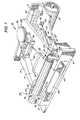
- Figure 1 is an isometric view of an exemplary laser driven raster scanner embodying the present invention;
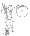
- Figure 2 is a side view of the scanner shown in Figure 1, and
- Figure 3 is a top view of the scanner shown in Figure 1.
- Referring to the drawings, a raster output scanner (ROS) 10 embodying the present invention is thereshown. As will appear,
scanner 10 generates latent electrostatic images on thephotoconductive surface 12 of a xerographic member 11 (shown here in the form of a drum) of a xerographic system (not shown). As will be understood by those familiar with the xerographic arts, the latent electrostatic images are created on the previously uniformly chargedphotoconductive surface 12 through selective exposure thereof in response to image information in the form of video image signals or pixels input tomodulator 27 ofscanner 10. The latent electrostatic image so created is thereafter developed and the developed image transferred to a suitable copy substrate material i.e. a copy sheet. The transferred image is thereafter fixed to form a permanent copy. Scanner 10 includes a generallyrectangular base 14 on which the several components ofscanner 10 are mounted in operative relation.Base 14 includesupright end supports 17, 18. Apolygon bridge support 19 extends downwardly from the upper portion of end support 17 to edge 14' ofbase 14. An oppositely facing, downwardly inclined side support 20 extends along one side ofbase 14 from the corner area ofend support 18 to the opposite end ofbase 14 proximate end support 17. The angle of inclination ofbridge support 19 and side support 20 is chosen to accommodate system optical requirements and ensure compactness.- A suitable source of high intensity light such as a laser, Light Emitting Diodes (LEDs), InfraRed (IR) laser diodes, etc. is provided. In the exemplary arrangement shown, a
laser assembly 15 with laser plasma tube orlaser 22 is mounted onend support 18 in a plane spaced above the plane ofbase 14. The longitudinal axis oflaser assembly 15 generally parallels edge 14' ofbase 14 andends support 17, 18. As will appear more fully herein,laser assembly 15 is mounted onend support 18 through an ajustable supporting mechanism which enables the beam of light output bylaser 22 to be aligned with the scanner optical axis in the field by service personnel. A beam focusing lens 67 is provided to focus the laser beam internal tomodulator 27, as will appear. - A
movable shutter 21 is disposed adjacent the beam discharge side oflaser assembly 15,shutter 21 serving to intercept thebeam 25 emitted bylaser 22 whenscanner 10 is not in use. This permitslaser 22 to be operated continuously, prolonging laser life. Asolenoid 23 is provided for withdrawingshutter 21 when it is desired to operatescanner 10. - The scanner optical path 0 leading from the beam discharge end of
laser assembly 15 to thephotoconductive surface 12 includes a firstbeam folding mirror 24 mounted onend support 18 adjacent the laser output.Beam modulator 27 is disposed downstream ofmirror 24 on the downwardly inclined side support 20.Mirror 24 intercepts thelaser beam 25 and turns, (i.e. folds) the beam through an angle of approximately 90° (in the horizontal plane) and downwardly towardmodulator 27.Modulator 27, which may comprise any suitable light modulator, as for example an acousto optic type modulator, selectively deflects thebeam 25 to provide zero-order and first-order beams order beam 31. The first-order beam 32 output bymodulator 27 strikes a secondbeam folding mirror 30 mounted on side support 20 downstream of and belowmodulator 27. - Mirror 30 reflects the first-order beam back toward
laser 22 along a generally horizontalplane paralleling base 14 to athird power mirror 33.Mirror 33, which is supported onbase 14 adjacent to and belowlaser 22, folds thebeam 32 back and directs the beam upwardly along a path generally paralleling the surface ofbridge support 19 towardpolygon 35. As will be seen, the scanner optical path O is such that the beam reflected bymirror 33 passes through one side oflens 45 to strike the mirrored facets of scanningpolygon 35. Power mirror 33 comprises a cylindrical mirror with power in the cross-scan plane.Mirror 33 functions to aid focusing of the cross-scan beam waist onto the facets of scanningpolygon 35.Lens 45 performs cross-scan focusing with the aid ofpower mirror 33 and collimates the beam in the polygon facet scan direction.- Scanning
polygon 35 is supported onshaft 37 ofpolygon drive motor 38 which in turn, is suspended from the underside ofbridge support 19, suitable bearing means (not shown) being provided to accommodate rotation ofshaft 37 and thepolygon 35 mounted thereon. The poly- gon/drive motor described preferably comprises a unitary assembly, the longitudinal axis of which, due to the mounting thereof onbridge support 19, is substantially perpendicular to the plane ofbridge support 19. Inasmuch asbridge support 19 is inclined, the plane of rotation ofpolygon 35 is inclined and generally parallel with the plane ofbridge support 19. - Polygon 35 has a plurality of mirror-
like facets 36 formed on the periphery thereof, facets reflecting the first-order beam 32 impinging thereon through a predetermined scan arc aspolygon 35 rotates to providescan beam 40. - The
scan beam 40 reflected byfacets 36 ofpolygon 35 pass throughimaging lens 45,lens 45 serving to focus the beam onto thephotoconductive surface 12.Lens 45 is mounted onbridge support 19 downstream ofpolygon 35. The now focusedscan beam 40 fromlens 45strikes mirror 33 which reflects the scan beam back along a plane substantially parallelingbase 14 to a fourthbeam folding mirror 47. Mirror 47, which is mounted onbase 14 adjacent end section 17, reflects the scan beam in a generally downward direction through slot-like aperture 49 inbase 14 to thephotoconductive surface 12 of the aforementioned xerographic system.- A pair of
pickoff mirrors base 14 in a position to intercept thescan beam 40 at the extremities of the beam sweep. Pickoff mirrors 50, 51, reflect the intercepted beam toward start-of-scan (SOS) and end-of-scan (EOS)detectors end support 18. SOS andEOS detectors detectors - As used herein, line sync (LS) is the period required for
scan beam 40 to travel fromSOS detector 53 toEOS detector 54. An image line which, as will be understood, normally includes certain steady state signals or pixels before and after the image signals or pixels representing the particular image to enable erasure of margin areas by thescan beam 40, is normally equal in period to that of the line sync (LS) signal. Where . the image line and line sync (LS) periods are not equal, compensating adjustments to the pixel clock frequency are automatically made to establish equilibrium, as will appear more fully herein. - During operation, the
light beam 25 emitted bylaser 22 is turned through an arc of more than 90° (in the horizontal plane) and reflected: downwardly byfold mirror 24 to the inlet ofmodulator 27. As described,modulator 27 either directs the beam against beam stop 29 (zero-order beam 31) or to fold mirror 30 (first-order beam 32) in accordance with the content of the video image signals input thereto. The first-order beam 32striking mirror 30 is reflected back in the direction oflaser 22 but along a lower level ofscanner 10 topower mirror 33 disposed in the area belowlaser 22.Mirror 33 reverses (i.e. folds) thebeam 32 and turns the beam upwardly to cause the beam to impinge against the mirror-like facets 36 of the rotatingpolygon 35. Polygon 35 sweeps the light beam through a preset scan arc and reverses (i.e. folds) the beam direction so that thescan beam 40 passes throughlens 45 topower mirror 33. As will be understood,lens 45 serves tv focus thescan beam 40 onto thephotoconductive surface 19. As thescan beam 40 emitted fromlens 45 sweeps acrossmirror 33, the beam is reversed (i.e. folded) and directed forward bymirror 33 to foldmirror 47.Mirror 47 turns thescan beam 40 downwardly throughscan slot 49 to impinge on the photoreceptor 11. - As the
scan beam 40 is swept bypolygon 35 through the scan arc, pickoff mirrors 50, 51 intercept the beam. Light reflected bymirrors EOS detectors - Where replacement or off-line servicing is required, the
laser assembly 15 is removed fromscanner 10 by releasingspring retainers
Claims (5)
1. A raster scanner including a source (1 5) of a beam (25) of high-intensity radiation, a plurality of mirrors (24, 30, 33, 36, 47) cooperable to form an optical path for causing the beam to impinge on an object (12) to be scanned, the said mirrors including a rotatable prismatic mirror (polygon) (35) for scanning the beam characterised by a first mirror (24) for reflecting the beam towards a plane (p); which is in substance parallel to a line (1) connecting the source (15) and the polygon (35); a second mirror (30) for reflecting the beam from the first mirror so that it lies in the said plane and is reflected laterally towards the centerline of the scanner, and a third mirror (33) for reflecting the beam from the second mirror (30) at an angle (a) to the plane and towards the rotary polygon (35) which intercepts the beam and reflects it back to the third mirror (33), from which it is reflected so as to lie in the said plane (p), and from there be reflected towards the object (12) to be scanned by the beam.
2. The raster scanner according to claim 1, including lens means (45) for focussing said scan beam on the object to be scanned, said lens means being disposed to intercept the beam between said polygon (35) and said third mirror (33).
3. The raster scanner according to claim 1 or 2, including a modulator (27) for modulating said beam in response to image signals, said modulator being disposed in the beam path between said first and second mirrors (24, 30).
4. The raster scanner according to any preceding claim, in which the optical path length between said source (15) and said polygon (35) is substantially equal to the distance between said polygon (35) and the object (12) to be scanned.
5. The raster scanner as claimed in any preceding claim, including a fourth mirror (47) intercepting the said plane so as to reflect the beam leaving the third mirror (33) for the second time out of the plane towards member (12) being swept by the beam.
Applications Claiming Priority (2)
| Application Number | Priority Date | Filing Date | Title |
|---|---|---|---|
| US06/191,979US4397521A (en) | 1980-09-29 | 1980-09-29 | Double pass optical system for raster scanners |
| US191979 | 1980-09-29 |
Publications (2)
| Publication Number | Publication Date |
|---|---|
| EP0049165A1 EP0049165A1 (en) | 1982-04-07 |
| EP0049165B1true EP0049165B1 (en) | 1984-06-27 |
Family
ID=22707711
Family Applications (1)
| Application Number | Title | Priority Date | Filing Date |
|---|---|---|---|
| EP81304513AExpiredEP0049165B1 (en) | 1980-09-29 | 1981-09-29 | Raster scanners |
Country Status (5)
| Country | Link |
|---|---|
| US (1) | US4397521A (en) |
| EP (1) | EP0049165B1 (en) |
| JP (1) | JPS5787674A (en) |
| CA (1) | CA1166051A (en) |
| DE (1) | DE3164445D1 (en) |
Families Citing this family (18)
| Publication number | Priority date | Publication date | Assignee | Title |
|---|---|---|---|---|
| US4561023A (en)* | 1983-08-16 | 1985-12-24 | Xerox Corporation | Dampening system for micro-deflector scanning beam modulator |
| DE3601828A1 (en)* | 1985-01-23 | 1986-07-24 | Canon K.K., Tokio/Tokyo | OPTICAL LIGHT SCAN SYSTEM OF AN IMAGE OUTPUT SCANNER WITH AN ELECTROMECHANICAL LIGHT MODULATOR |
| JPS61169812A (en)* | 1985-01-23 | 1986-07-31 | Canon Inc | Light scanning optical system |
| US4759593A (en)* | 1986-03-21 | 1988-07-26 | Eastman Kodak Company | High resolution optical scanner |
| US4779944A (en)* | 1987-11-25 | 1988-10-25 | Holotek Ltd. | Integrated laser beam scanning system |
| US5196957A (en)* | 1990-03-20 | 1993-03-23 | Olive Tree Technology, Inc. | Laser scanner with post-facet lens system |
| US5247383A (en)* | 1990-03-20 | 1993-09-21 | Olive Tree Technology, Inc. | Scanner with a post facet lens system |
| US5173797A (en)* | 1990-05-08 | 1992-12-22 | Xerox Corporation | Rotating mirror optical scanner with grooved grease bearings |
| US5294943A (en)* | 1991-10-31 | 1994-03-15 | Eastman Kodak Company | Method and apparatus for alignment of scan line optics with target medium |
| US5214441A (en)* | 1991-10-31 | 1993-05-25 | Eastman Kodak Company | Method and apparatus for alignment of scan line optics with target medium using external adjusting members |
| US5237348A (en)* | 1991-10-31 | 1993-08-17 | Eastman Kodak Company | Method and apparatus for alignment of scan line optics with target medium using external adjusting members |
| US5151810A (en)* | 1991-10-31 | 1992-09-29 | Eastman Kodak Company | Method for alignment of scan line optics with target medium |
| JPH05308599A (en)* | 1991-12-30 | 1993-11-19 | Samsung Electron Co Ltd | Printing method and printing apparatus suitable for the same |
| JP3109358B2 (en)* | 1993-12-16 | 2000-11-13 | 富士ゼロックス株式会社 | Mounting structure of scanning optical system |
| JPH07322014A (en)* | 1994-05-26 | 1995-12-08 | Konica Corp | Picture reader |
| JPH09127750A (en)* | 1995-10-26 | 1997-05-16 | Ricoh Co Ltd | Image forming device |
| US7009786B2 (en)* | 2004-04-22 | 2006-03-07 | Eastman Kodak Company | Adjustable mount for cylindrical lens |
| CN108681095A (en)* | 2018-05-21 | 2018-10-19 | 武汉华日精密激光股份有限公司 | Pulse shortener and femtosecond pulse laser |
Family Cites Families (11)
| Publication number | Priority date | Publication date | Assignee | Title |
|---|---|---|---|---|
| US3752558A (en)* | 1971-06-28 | 1973-08-14 | Decision Consultants | Document scanner |
| US3867569A (en) | 1974-02-25 | 1975-02-18 | Bell Telephone Labor Inc | Compact flatbed page scanner |
| US3898627A (en)* | 1974-03-22 | 1975-08-05 | Ibm | Optical printer having serializing buffer for use with variable length binary words |
| US4058828A (en)* | 1975-05-27 | 1977-11-15 | Eastman Kodak Company | Document copying apparatus |
| JPS588B2 (en)* | 1975-10-15 | 1983-01-05 | 富士写真フイルム株式会社 | Hikari Bee Mususasouchi |
| CH608628A5 (en)* | 1975-11-21 | 1979-01-15 | Sick Optik Elektronik Erwin | |
| US4171902A (en)* | 1976-02-19 | 1979-10-23 | Canon Kabushiki Kaisha | Information processing system having an optic axis adjusting mirror device |
| US4054928A (en)* | 1976-02-20 | 1977-10-18 | The Mead Corporation | Laser operated scanning and printing system |
| JPS53137631A (en)* | 1977-05-07 | 1978-12-01 | Canon Inc | Terminal unit for information processing |
| US4274703A (en)* | 1977-08-01 | 1981-06-23 | Xerox Corporation | High-efficiency symmetrical scanning optics |
| US4284994A (en)* | 1979-07-30 | 1981-08-18 | Eikonix Corporation | Laser beam recorder |
- 1980
- 1980-09-29USUS06/191,979patent/US4397521A/ennot_activeExpired - Lifetime
- 1981
- 1981-08-20CACA000384307Apatent/CA1166051A/ennot_activeExpired
- 1981-09-28JPJP56153522Apatent/JPS5787674A/enactiveGranted
- 1981-09-29DEDE8181304513Tpatent/DE3164445D1/ennot_activeExpired
- 1981-09-29EPEP81304513Apatent/EP0049165B1/ennot_activeExpired
Also Published As
| Publication number | Publication date |
|---|---|
| JPH0243161B2 (en) | 1990-09-27 |
| DE3164445D1 (en) | 1984-08-02 |
| CA1166051A (en) | 1984-04-24 |
| JPS5787674A (en) | 1982-06-01 |
| EP0049165A1 (en) | 1982-04-07 |
| US4397521A (en) | 1983-08-09 |
Similar Documents
| Publication | Publication Date | Title |
|---|---|---|
| EP0049165B1 (en) | Raster scanners | |
| US5526166A (en) | Optical system for the correction of differential scanline bow | |
| EP0049164B1 (en) | Optical system | |
| KR100319354B1 (en) | Optical scanning apparatus and image forming apparatus and electrophotographic printer using such scanning apparatus | |
| US3426144A (en) | Transceiver apparatus for transmitting and recording optical information | |
| EP0529785A1 (en) | Raster output scanner with process direction spot position control | |
| EP0050425B1 (en) | A method of replacing a laser | |
| US6519070B2 (en) | Optical scanning apparatus, multi-beam optical scanning apparatus, and image forming apparatus using the same | |
| EP0072182B1 (en) | Multi-function document processor | |
| JP5343063B2 (en) | Optical scanning apparatus and image forming apparatus | |
| US6567201B1 (en) | Optical scanner | |
| US4355859A (en) | Field replaceable laser apparatus for raster scanner | |
| US4630130A (en) | Scanning system for controlling stray beams caused by undesirable optical reflections | |
| US5081544A (en) | Optical scanning apparatus | |
| JPH03245116A (en) | Optical device and image forming device or image information reading device into which this optical device is incorporated | |
| JPH0519598A (en) | Exposure equipment for electrophotographic equipment | |
| CA1179536A (en) | Double pass optical system for raster scanners | |
| CA1179537A (en) | Double pass scanning system | |
| JP3128860B2 (en) | Laser scanning device | |
| KR100243142B1 (en) | Compact color printer | |
| JPH03197916A (en) | optical equipment | |
| JPH1144857A (en) | Optical deflection scanner | |
| JP3078680B2 (en) | Optical scanning device | |
| JPH01200219A (en) | Light beam scanning optical system | |
| JPH08220457A (en) | Optical scanner |
Legal Events
| Date | Code | Title | Description |
|---|---|---|---|
| PUAI | Public reference made under article 153(3) epc to a published international application that has entered the european phase | Free format text:ORIGINAL CODE: 0009012 | |
| AK | Designated contracting states | Designated state(s):DE GB | |
| 17P | Request for examination filed | Effective date:19821004 | |
| GRAA | (expected) grant | Free format text:ORIGINAL CODE: 0009210 | |
| AK | Designated contracting states | Designated state(s):DE GB | |
| REF | Corresponds to: | Ref document number:3164445 Country of ref document:DE Date of ref document:19840802 | |
| PLBE | No opposition filed within time limit | Free format text:ORIGINAL CODE: 0009261 | |
| STAA | Information on the status of an ep patent application or granted ep patent | Free format text:STATUS: NO OPPOSITION FILED WITHIN TIME LIMIT | |
| 26N | No opposition filed | ||
| PGFP | Annual fee paid to national office [announced via postgrant information from national office to epo] | Ref country code:GB Payment date:19981001 Year of fee payment:18 | |
| PGFP | Annual fee paid to national office [announced via postgrant information from national office to epo] | Ref country code:DE Payment date:19981005 Year of fee payment:18 | |
| PG25 | Lapsed in a contracting state [announced via postgrant information from national office to epo] | Ref country code:GB Free format text:LAPSE BECAUSE OF NON-PAYMENT OF DUE FEES Effective date:19990929 | |
| GBPC | Gb: european patent ceased through non-payment of renewal fee | Effective date:19990929 | |
| PG25 | Lapsed in a contracting state [announced via postgrant information from national office to epo] | Ref country code:DE Free format text:LAPSE BECAUSE OF NON-PAYMENT OF DUE FEES Effective date:20000701 |