EP0049031B1 - Ball joints and liners therefor - Google Patents
Ball joints and liners thereforDownload PDFInfo
- Publication number
- EP0049031B1 EP0049031B1EP81303265AEP81303265AEP0049031B1EP 0049031 B1EP0049031 B1EP 0049031B1EP 81303265 AEP81303265 AEP 81303265AEP 81303265 AEP81303265 AEP 81303265AEP 0049031 B1EP0049031 B1EP 0049031B1
- Authority
- EP
- European Patent Office
- Prior art keywords
- liner
- annulus
- tongues
- recess
- projection
- Prior art date
- Legal status (The legal status is an assumption and is not a legal conclusion. Google has not performed a legal analysis and makes no representation as to the accuracy of the status listed.)
- Expired
Links
- 210000002105tongueAnatomy0.000claimsdescription29
- 239000000463materialSubstances0.000claimsdescription5
- 229920003023plasticPolymers0.000claimsdescription4
- 239000004033plasticSubstances0.000claimsdescription4
- 230000001154acute effectEffects0.000claimsdescription3
- 230000008602contractionEffects0.000claimsdescription3
- 230000010339dilationEffects0.000claimsdescription3
- 230000000717retained effectEffects0.000claimsdescription3
- 238000004519manufacturing processMethods0.000description6
- 238000010276constructionMethods0.000description3
- 230000000916dilatatory effectEffects0.000description2
- 238000003780insertionMethods0.000description2
- 230000037431insertionEffects0.000description2
- 239000002184metalSubstances0.000description2
- DHKHKXVYLBGOIT-UHFFFAOYSA-Nacetaldehyde Diethyl AcetalNatural productsCCOC(C)OCCDHKHKXVYLBGOIT-UHFFFAOYSA-N0.000description1
- 230000000295complement effectEffects0.000description1
- 229920001577copolymerPolymers0.000description1
- 238000000034methodMethods0.000description1
- 238000000465mouldingMethods0.000description1
- 125000006850spacer groupChemical group0.000description1
- 230000003313weakening effectEffects0.000description1
Images


Classifications
- B—PERFORMING OPERATIONS; TRANSPORTING
- B60—VEHICLES IN GENERAL
- B60K—ARRANGEMENT OR MOUNTING OF PROPULSION UNITS OR OF TRANSMISSIONS IN VEHICLES; ARRANGEMENT OR MOUNTING OF PLURAL DIVERSE PRIME-MOVERS IN VEHICLES; AUXILIARY DRIVES FOR VEHICLES; INSTRUMENTATION OR DASHBOARDS FOR VEHICLES; ARRANGEMENTS IN CONNECTION WITH COOLING, AIR INTAKE, GAS EXHAUST OR FUEL SUPPLY OF PROPULSION UNITS IN VEHICLES
- B60K20/00—Arrangement or mounting of change-speed gearing control devices in vehicles
- B60K20/02—Arrangement or mounting of change-speed gearing control devices in vehicles of initiating means
- F—MECHANICAL ENGINEERING; LIGHTING; HEATING; WEAPONS; BLASTING
- F16—ENGINEERING ELEMENTS AND UNITS; GENERAL MEASURES FOR PRODUCING AND MAINTAINING EFFECTIVE FUNCTIONING OF MACHINES OR INSTALLATIONS; THERMAL INSULATION IN GENERAL
- F16C—SHAFTS; FLEXIBLE SHAFTS; ELEMENTS OR CRANKSHAFT MECHANISMS; ROTARY BODIES OTHER THAN GEARING ELEMENTS; BEARINGS
- F16C11/00—Pivots; Pivotal connections
- F16C11/04—Pivotal connections
- F16C11/06—Ball-joints; Other joints having more than one degree of angular freedom, i.e. universal joints
- F16C11/0614—Ball-joints; Other joints having more than one degree of angular freedom, i.e. universal joints the female part of the joint being open on two sides
- F—MECHANICAL ENGINEERING; LIGHTING; HEATING; WEAPONS; BLASTING
- F16—ENGINEERING ELEMENTS AND UNITS; GENERAL MEASURES FOR PRODUCING AND MAINTAINING EFFECTIVE FUNCTIONING OF MACHINES OR INSTALLATIONS; THERMAL INSULATION IN GENERAL
- F16H—GEARING
- F16H59/00—Control inputs to control units of change-speed- or reversing-gearings for conveying rotary motion
- F16H59/02—Selector apparatus
- F16H2059/026—Details or special features of the selector casing or lever support
- F16H2059/0269—Ball joints or spherical bearings for supporting the lever
Definitions
- This inventionrelates to liners for ball joints, and ball joints including such liners.
- a conventional ball jointsuch as used to mount a gear selector lever on a gearbox, comprises a housing having a recess therein, which is usually cylindrical, a ball element pivotably received in the recess, and a bearing liner between the ball element and the recess.
- lineras, for example disclosed in British patent specification No: 1,187,187, comprises an annulus of resiliently deformable plastics material having an inner spherical bearing surface.
- at least one end portion of the annulushas a plurality of axially extending cicumferentially spaced tongues. These tongues spread radially outwardly to dilate the end of the annulus as the ball element is inserted into the annulus.
- the tongueshave radially outwardly extending projections which engage in a cavity in the recess in the housing when the ball element is inserted into the liner. In both cases the liner and ball element must be inserted into the housing from opposite sides, and the ball element can be withdrawn from the liner using the same force as applied on assembly.
- a retainersuch as a spring circlip or a nut must be secured to the housing in contact with the liner.
- a gear selecter leverif a nut is used as a retainer, it is normally positioned above the ball element, where it limits the range of movement of the lever. If a circlip is used, it is usually necessary to insert shims into the housing to compensate for variations in size of the ball element and the recess due to manufacturing tolerances. Assembly of the joint is therefore relatively complicated.
- a liner for a ball jointcomprising an annulus of resiliently deformable plastics material having an inner spherical bearing surface, at least one end portion of the annulus having a plurality of axially extending circumferentially spaced tongues which can be deflected radially to dilate the end of the annulus, at least some of the tongues having inner surfaces which lie in the spherical bearing surface, and at least one of the tongues having a radially outwardly extending projection for retaining the liner in a bearing mounting characterised in that the inner surface of the or each tongue having a radially outwardly extending projection is spaced radially outwardly from the spherical bearing surface.
- the lineris mounted on the ball element of a ball joint with its spherical surface in sliding contact with a spherical surface of the ball element, the tongues undergoing radial deflection to dilate the end of the annulus as the ball element is inserted therein.
- the assembled ball element and annuluscan then be mounted in a housing provided with a recess for receiving the ball element and liner, the liner being retained in the recess by engagement of the or each projection with a radial cavity, for example a circumferential groove, in the recess.
- the tonguescan be deflected radially inwardly thereby allowing the radial projections to be inserted into the recess in the housing.
- the or each projectionpreferably has a radially outer surface which is inclined at an acute angle to the external surface of the liner in a direction away from the axis of the annulus and towards the central radial plane thereof.
- the projectionpreferably has another part of its surface inclined in the opposite direction so that the projections are wedge-shaped in axial cross section. This ensures positive engagement of the projections in the cavity of the recess even when the relative radial and axial positions of the inner surface and cavity vary within manufacturing tolerances.
- the other end portion of the annulusalso has a plurality of axially extending circumferentially spaced tongues the inner surfaces of which lie in the spherical bearing surface of the annulus.
- This constructionpermits the ball element to be introduced into the annulus from either end.
- the tonguesare preferably so disposed relative to each other that dilation of one end of the annulus produces a contraction in the other end of the annulus.
- the tonguesmay be formed by slots in the annulus extending axially from the ends of the annulus, the slots at each end preferably being circumferentially interleaved to avoid weakening the annulus at its central radial plane.
- the linercan also preferably expand radially, thus accommodating variations in size of the ball element within manufacturing tolerances.
- a gear selector lever assembly for a gearboxcomprises a housing 1 having a cylindrical recess 2 the internal surface of which includes a radial cavity in the form of a circumferential groove 3.
- a ball element 5 of sintered metal press fitted on to a selector lever 6is received in the recess 2.
- the ball element 5has a spherical surface 7 of smaller diameter than the recess 5, and is retained in the recess by a liner 10, illustrated in detail in Figures 2 and 3.
- the liner 10comprises a one-piece moulding of resiliently deformable plastics material, such as a self-lubricating acetal copolymer of the kind conventionally used as a bearing liner material.
- the liner 10is an annulus having a generally cylindrical external surface 11 which is a sliding fit with the recess 2.
- the internal surface 12 of the linerdefines a spherical bearing surface of complementary diameter to that of the spherical surface 7 of the ba)! element 5 so that the spherical surface 7 of the ball element 5 can make a sliding contact therewith.
- Each end of the liner 10is provided with eight axial slots 15.
- the slots 15 at each endextend beyond the central radial plane of the liner 10 and are interleaved circumferentially with the slots at the opposite end so that the annulus has a sinuous shape which is both flexible and strong.
- Adjacent pairs of slotsdivide the end portions of the annulus into eight circumferentially spaced tongues 16,16a, 16b.
- the tongues at either end of the liner 10can be deflected radially outwardly to dilate the end of the liner 10, a dilation at one end being accompanied by a contraction at the other end of the annulus. This ⁇ aIIows the ball element 5 to be inserted into either end of the annulus as illustrated in Figure 4.
- All the tongues 16 at one end of the annulushave an inner surface 17 which lies in the spherical bearing surface 12 of the liner 10. At the other end of the annulus however, only four of the tongues 16a have inner surfaces 17a lying in the bearing surface of the liner.
- the other four tongues, 16bhave inner surfaces 17b which are spaced radially from the spherical bearing surface 12 of the annulus 10, and which lie in a cylindrical surface parallel to the external surface 11 of the annulus 10 and tangential to the bearing surface 12 at the central radial plane of the liner 10.
- These four tongues 16bare also provided with radially outwardly extending projections 18.
- Each projectionis generally wedge-shaped in axial cross-section having a leading radially outer conical surface 18a which is inclined outwardly at an angle A to the radial plane away from the central axis of the liner and towards the central plane thereof, and a trailing outer conical surface 18b which is inclined in the opposite direction at a smaller angle, B, to the radial plane.
- the bases of these projectionsare axially wider than the groove 3 so that the extremities of the projections engage in the circumferential groove 3 and retaining the liner 10 and the ball element 5 in the recess 2.
- the ball element 5is partially inserted into the end of the annulus opposite the projections 18, thus dilating the end into which it is inserted and contracting the opposite end.
- the contracted end of the annuluscan then easily be introduced into the mouth of the recess 3, as illustrated in Figure 4.
- the wedge shapes of the projections 18facilitate this movement.
- the ball element 5is then pushed firmly into the liner 10 so that its spherical surface 7 lies in contact with the bearing surface 12 of the liner. This movement causes the dilated end of the liner 10 to return to its normal size, allowing the liner to slide into the recess 3. Since the four tongues 16b carrying the projections 18 have inner surfaces spaced from the spherical bearing surface 12 of the liner 10, the engagement of the projections 18 with the cylindrical internal surface of the recess 2 deflects the tongues 16b radially inwardly, so that the projections 18 are accommodated within the recess 2, as illustrated in Figure 5. Since the ,slots 15 allow radial expansion of the liner 10, variations in size of the ball element 5 due to manufacturing tolerances can be accommodated.
Landscapes
- Engineering & Computer Science (AREA)
- General Engineering & Computer Science (AREA)
- Mechanical Engineering (AREA)
- Chemical & Material Sciences (AREA)
- Combustion & Propulsion (AREA)
- Transportation (AREA)
- Pivots And Pivotal Connections (AREA)
Description
- This invention relates to liners for ball joints, and ball joints including such liners.
- A conventional ball joint, such as used to mount a gear selector lever on a gearbox, comprises a housing having a recess therein, which is usually cylindrical, a ball element pivotably received in the recess, and a bearing liner between the ball element and the recess.
- One known kind of liner as, for example disclosed in British patent specification No: 1,187,187, comprises an annulus of resiliently deformable plastics material having an inner spherical bearing surface. In order to allow the liner to be pushed on to the ball element, at least one end portion of the annulus has a plurality of axially extending cicumferentially spaced tongues. These tongues spread radially outwardly to dilate the end of the annulus as the ball element is inserted into the annulus. In a similar liner, disclosed in DE-U-7301171, the tongues have radially outwardly extending projections which engage in a cavity in the recess in the housing when the ball element is inserted into the liner. In both cases the liner and ball element must be inserted into the housing from opposite sides, and the ball element can be withdrawn from the liner using the same force as applied on assembly.
- In orderto prevent unintentional removal of the ball element from the liner, a retainer, such as a spring circlip or a nut must be secured to the housing in contact with the liner. In the case of a gear selecter lever, if a nut is used as a retainer, it is normally positioned above the ball element, where it limits the range of movement of the lever. If a circlip is used, it is usually necessary to insert shims into the housing to compensate for variations in size of the ball element and the recess due to manufacturing tolerances. Assembly of the joint is therefore relatively complicated.
- According to the present invention, there is provided a liner for a ball joint comprising an annulus of resiliently deformable plastics material having an inner spherical bearing surface, at least one end portion of the annulus having a plurality of axially extending circumferentially spaced tongues which can be deflected radially to dilate the end of the annulus, at least some of the tongues having inner surfaces which lie in the spherical bearing surface, and at least one of the tongues having a radially outwardly extending projection for retaining the liner in a bearing mounting characterised in that the inner surface of the or each tongue having a radially outwardly extending projection is spaced radially outwardly from the spherical bearing surface.
- In use the liner is mounted on the ball element of a ball joint with its spherical surface in sliding contact with a spherical surface of the ball element, the tongues undergoing radial deflection to dilate the end of the annulus as the ball element is inserted therein. The assembled ball element and annulus can then be mounted in a housing provided with a recess for receiving the ball element and liner, the liner being retained in the recess by engagement of the or each projection with a radial cavity, for example a circumferential groove, in the recess. Since the or each tongue of the annulus carrying the radial projections has an inner surface spaced radially from the spherical bearing surface of the annulus, and therefore of the ball element, the tongues can be deflected radially inwardly thereby allowing the radial projections to be inserted into the recess in the housing.
- In order to facilitate insertion of the annulus into the recess, the or each projection preferably has a radially outer surface which is inclined at an acute angle to the external surface of the liner in a direction away from the axis of the annulus and towards the central radial plane thereof. As a result, the engagement of the projection with the mouth of the recess exerts a radially inward force on the tongues. In addition, the projection preferably has another part of its surface inclined in the opposite direction so that the projections are wedge-shaped in axial cross section. This ensures positive engagement of the projections in the cavity of the recess even when the relative radial and axial positions of the inner surface and cavity vary within manufacturing tolerances.
- Preferably the other end portion of the annulus also has a plurality of axially extending circumferentially spaced tongues the inner surfaces of which lie in the spherical bearing surface of the annulus. This construction permits the ball element to be introduced into the annulus from either end. With such a construction, the tongues are preferably so disposed relative to each other that dilation of one end of the annulus produces a contraction in the other end of the annulus. For example, the tongues may be formed by slots in the annulus extending axially from the ends of the annulus, the slots at each end preferably being circumferentially interleaved to avoid weakening the annulus at its central radial plane. With such a construction, insertion of the one end of the annulus into the recess is facilitated by dilating the other end of the annulus by partially inserting the ball element. The liner can also preferably expand radially, thus accommodating variations in size of the ball element within manufacturing tolerances.
- In order that the invention may be better understood, a preferred embodiment thereof will now be described, by way of example only, with reference to the accompanying drawings, in which:
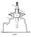
- Figure 1 is a cross-section through a ball joint incorporating a liner in accordance with the invention;
- Figure 2 is an end view on an enlarged scale of a liner incorporated in the ball joint of Figure 1;
- Figure 3 is an axial cross-section of the liner of Figure 2;
- Figure 4 is a cross-section on an enlarged scale through part of the ball joint of Figure 1 during a first stage of assembly; and
- Figure 5 is a similar cross-section to Figure 4 showing the ball joint during a later stage of assembly.
- Referring to the drawings, a gear selector lever assembly for a gearbox comprises a
housing 1 having acylindrical recess 2 the internal surface of which includes a radial cavity in the form of a circumferential groove 3. - A
ball element 5 of sintered metal press fitted on to aselector lever 6 is received in therecess 2. Theball element 5 has aspherical surface 7 of smaller diameter than therecess 5, and is retained in the recess by aliner 10, illustrated in detail in Figures 2 and 3. - The
liner 10 comprises a one-piece moulding of resiliently deformable plastics material, such as a self-lubricating acetal copolymer of the kind conventionally used as a bearing liner material. Theliner 10 is an annulus having a generally cylindricalexternal surface 11 which is a sliding fit with therecess 2. Theinternal surface 12 of the liner defines a spherical bearing surface of complementary diameter to that of thespherical surface 7 of the ba)!element 5 so that thespherical surface 7 of theball element 5 can make a sliding contact therewith. - Each end of the
liner 10 is provided with eightaxial slots 15. Theslots 15 at each end extend beyond the central radial plane of theliner 10 and are interleaved circumferentially with the slots at the opposite end so that the annulus has a sinuous shape which is both flexible and strong. - Adjacent pairs of slots divide the end portions of the annulus into eight circumferentially spaced
tongues liner 10 can be deflected radially outwardly to dilate the end of theliner 10, a dilation at one end being accompanied by a contraction at the other end of the annulus. This·aIIows theball element 5 to be inserted into either end of the annulus as illustrated in Figure 4. - All the
tongues 16 at one end of the annulus have aninner surface 17 which lies in the spherical bearingsurface 12 of theliner 10. At the other end of the annulus however, only four of thetongues 16a haveinner surfaces 17a lying in the bearing surface of the liner. The other four tongues, 16b haveinner surfaces 17b which are spaced radially from the spherical bearingsurface 12 of theannulus 10, and which lie in a cylindrical surface parallel to theexternal surface 11 of theannulus 10 and tangential to thebearing surface 12 at the central radial plane of theliner 10. These fourtongues 16b are also provided with radially outwardly extendingprojections 18. Each projection is generally wedge-shaped in axial cross-section having a leading radially outer conical surface 18a which is inclined outwardly at an angle A to the radial plane away from the central axis of the liner and towards the central plane thereof, and a trailing outer conical surface 18b which is inclined in the opposite direction at a smaller angle, B, to the radial plane. The bases of these projections are axially wider than the groove 3 so that the extremities of the projections engage in the circumferential groove 3 and retaining theliner 10 and theball element 5 in therecess 2. - In order to assemble the joint, the
ball element 5 is partially inserted into the end of the annulus opposite theprojections 18, thus dilating the end into which it is inserted and contracting the opposite end. The contracted end of the annulus can then easily be introduced into the mouth of the recess 3, as illustrated in Figure 4. The wedge shapes of theprojections 18 facilitate this movement. - The
ball element 5 is then pushed firmly into theliner 10 so that itsspherical surface 7 lies in contact with thebearing surface 12 of the liner. This movement causes the dilated end of theliner 10 to return to its normal size, allowing the liner to slide into the recess 3. Since the fourtongues 16b carrying theprojections 18 have inner surfaces spaced from the spherical bearingsurface 12 of theliner 10, the engagement of theprojections 18 with the cylindrical internal surface of therecess 2 deflects thetongues 16b radially inwardly, so that theprojections 18 are accommodated within therecess 2, as illustrated in Figure 5. Since the ,slots 15 allow radial expansion of theliner 10, variations in size of theball element 5 due to manufacturing tolerances can be accommodated. - Further movement of the
liner 10 andball 5 into the recess brings the projections into registry with the groove 3, whereupon thetongues 16b expand radially outwardly to retain the liner in position. Since theprojections 18 are wedge shaped, in axial cross-section, with their faces inclined at acute angles in opposite directions to the central radial plane, the projections will engage in the groove 3 regardless of small variations in the relative positions of the groove 3 andliner 10 due to manufacturing tolerances. - No further fixing of the
selector lever 6 to thehousing 1 is required, so that the movement of thelever 6 relative to thehousing 1 is unencumbered by retainers such as nuts. Moreover, the use of aflexible liner 10 with wedge-shaped retaining projections 18 accommodates variations in size of therecess 2 in the housing and of theball element 5 within manufacturing tolerances, thereby avoiding the need for shims or other spacers. Indeed variations within relatively large tolerances can be accommodated, which allows the components of the assembly to be manufactured by cheaper methods. For example, theball element 5 may be of sintered metal.
Claims (6)
Applications Claiming Priority (2)
| Application Number | Priority Date | Filing Date | Title |
|---|---|---|---|
| GB8023564 | 1980-07-18 | ||
| GB8023564AGB2080401A (en) | 1980-07-18 | 1980-07-18 | Ball joint and liner therefor |
Publications (2)
| Publication Number | Publication Date |
|---|---|
| EP0049031A1 EP0049031A1 (en) | 1982-04-07 |
| EP0049031B1true EP0049031B1 (en) | 1984-03-07 |
Family
ID=10514873
Family Applications (1)
| Application Number | Title | Priority Date | Filing Date |
|---|---|---|---|
| EP81303265AExpiredEP0049031B1 (en) | 1980-07-18 | 1981-07-16 | Ball joints and liners therefor |
Country Status (4)
| Country | Link |
|---|---|
| EP (1) | EP0049031B1 (en) |
| JP (1) | JPS5779320A (en) |
| DE (1) | DE3162516D1 (en) |
| GB (1) | GB2080401A (en) |
Cited By (1)
| Publication number | Priority date | Publication date | Assignee | Title |
|---|---|---|---|---|
| DE3244383A1 (en)* | 1982-12-01 | 1984-06-07 | Friedrich Grohe Armaturenfabrik Gmbh & Co, 5870 Hemer | Ball-joint support |
Families Citing this family (8)
| Publication number | Priority date | Publication date | Assignee | Title |
|---|---|---|---|---|
| US4591276A (en)* | 1984-01-14 | 1986-05-27 | Skf Gmbh | Radial ball-and-socket bearing |
| JPS6345212U (en)* | 1986-09-04 | 1988-03-26 | ||
| DE4127730A1 (en)* | 1991-08-22 | 1993-03-04 | Ford Werke Ag | SHIFT LEVER BEARING FOR TRANSMISSION OF MOTOR VEHICLES |
| DE4420487C1 (en)* | 1994-06-11 | 1995-06-01 | Trw Fahrwerksyst Gmbh & Co | Hollow pivot joint assembly |
| DE19523618A1 (en)* | 1995-07-03 | 1997-01-09 | Opel Adam Ag | Manual transmission for actuating a change gear |
| GB2309739B (en)* | 1996-01-31 | 2000-01-19 | Ivor Maldwyn Hugh Pagden | Ball joint mount |
| US20010043767A1 (en) | 2000-05-18 | 2001-11-22 | Thk Co., Ltd | Spherical bearing and method for manufacturing the same |
| JP3862669B2 (en) | 2003-04-16 | 2006-12-27 | Thk株式会社 | Manufacturing method of spherical bearing |
Citations (2)
| Publication number | Priority date | Publication date | Assignee | Title |
|---|---|---|---|---|
| US3736567A (en)* | 1971-09-08 | 1973-05-29 | Bunker Ramo | Program sequence control |
| US4131943A (en)* | 1976-06-30 | 1978-12-26 | Tokyo Shibaura Electric Co., Ltd. | Microprogrammed computer employing a decode read only memory (DROM) and a microinstruction read only memory (ROM) |
Family Cites Families (8)
| Publication number | Priority date | Publication date | Assignee | Title |
|---|---|---|---|---|
| DE7301171U (en)* | 1973-11-15 | Ehrenreich A & Cie | Bearing shell for a ball joint | |
| US3367728A (en)* | 1965-06-01 | 1968-02-06 | Scott & Fetzer Co | Self-aligning bearing means |
| DE1575539B2 (en)* | 1967-01-19 | 1971-10-07 | Lemfbrder Metallwaren AG, 2844 Lemförde | BALL JOINT IN PARTICULAR FOR THE SUSPENSION AND LINKAGE OF THE WHEELS OF MOTOR VEHICLES |
| FR1588729A (en)* | 1967-10-27 | 1970-04-17 | ||
| DE2201874A1 (en)* | 1972-01-15 | 1973-07-19 | Bosch Gmbh Robert | BEARING BUSH |
| JPS5045162A (en)* | 1973-08-14 | 1975-04-23 | ||
| JPS5098180U (en)* | 1974-01-14 | 1975-08-15 | ||
| FR2456875A1 (en)* | 1979-05-15 | 1980-12-12 | Dba | BALL JOINT |
- 1980
- 1980-07-18GBGB8023564Apatent/GB2080401A/ennot_activeWithdrawn
- 1981
- 1981-07-16EPEP81303265Apatent/EP0049031B1/ennot_activeExpired
- 1981-07-16DEDE8181303265Tpatent/DE3162516D1/ennot_activeExpired
- 1981-07-17JPJP56112065Apatent/JPS5779320A/enactiveGranted
Patent Citations (2)
| Publication number | Priority date | Publication date | Assignee | Title |
|---|---|---|---|---|
| US3736567A (en)* | 1971-09-08 | 1973-05-29 | Bunker Ramo | Program sequence control |
| US4131943A (en)* | 1976-06-30 | 1978-12-26 | Tokyo Shibaura Electric Co., Ltd. | Microprogrammed computer employing a decode read only memory (DROM) and a microinstruction read only memory (ROM) |
Non-Patent Citations (2)
| Title |
|---|
| ELECTRICAL DESIGN NEWS (E DN) vol. 25, March 1980, Denver, US BARON: "Control your next pipeline design with a microprogrammed sequencer", pages 157-162* |
| Le Nouvel Automatisme, Janvier-Fevrier 1979, pages 31-39* |
Cited By (1)
| Publication number | Priority date | Publication date | Assignee | Title |
|---|---|---|---|---|
| DE3244383A1 (en)* | 1982-12-01 | 1984-06-07 | Friedrich Grohe Armaturenfabrik Gmbh & Co, 5870 Hemer | Ball-joint support |
Also Published As
| Publication number | Publication date |
|---|---|
| EP0049031A1 (en) | 1982-04-07 |
| JPS5779320A (en) | 1982-05-18 |
| JPH0260887B2 (en) | 1990-12-18 |
| GB2080401A (en) | 1982-02-03 |
| DE3162516D1 (en) | 1984-04-12 |
Similar Documents
| Publication | Publication Date | Title |
|---|---|---|
| US4511277A (en) | Ball joints and liners therefor | |
| JP2875781B2 (en) | Zero clearance bearing | |
| US4591276A (en) | Radial ball-and-socket bearing | |
| US5193917A (en) | Rolling bearings for steering columns | |
| US4783183A (en) | Thrust bearing assembly | |
| US5015105A (en) | Crown-shaped cage for a radial bearing | |
| US3992117A (en) | Shaft retaining ring | |
| US4790672A (en) | Pressed sleeve bearing | |
| US4623270A (en) | Pocket cage for rolling bearing | |
| US6261005B1 (en) | Rolling bearing cage | |
| US4854141A (en) | Anti-rotation locking device including a torque limitation for a motor vehicle steering column | |
| EP0049031B1 (en) | Ball joints and liners therefor | |
| US6318900B1 (en) | Ball bearing mounting member | |
| EP1370780B1 (en) | Full complement taper roller bearing | |
| US5026179A (en) | Angular ball bearing method for assembling the same | |
| US5267797A (en) | Combined radial/axial friction bearing and method for its manufacture | |
| US5074680A (en) | Angular contact bearings and method for making the same | |
| JPS61197817A (en) | spacing retainer | |
| US5247848A (en) | Bearing for supporting the shift lever of the automotive transmission | |
| US4606655A (en) | Roller bearing | |
| US3446522A (en) | Internal retaining ring | |
| CA2225280A1 (en) | Snap connection system | |
| US4387939A (en) | Multi-part rolling bearing cage with snap fit interconnection | |
| US5885009A (en) | Cage for cylindrical rolling elements | |
| GB2184201A (en) | Axial retaining member |
Legal Events
| Date | Code | Title | Description |
|---|---|---|---|
| PUAI | Public reference made under article 153(3) epc to a published international application that has entered the european phase | Free format text:ORIGINAL CODE: 0009012 | |
| AK | Designated contracting states | Designated state(s):DE FR GB NL SE | |
| 17P | Request for examination filed | Effective date:19820201 | |
| RAP1 | Party data changed (applicant data changed or rights of an application transferred) | Owner name:FORD MOTOR COMPANY LIMITED Owner name:FORD-WERKE AKTIENGESELLSCHAFT Owner name:FORD FRANCE SOCIETE ANONYME | |
| GRAA | (expected) grant | Free format text:ORIGINAL CODE: 0009210 | |
| AK | Designated contracting states | Designated state(s):DE FR GB NL SE | |
| REF | Corresponds to: | Ref document number:3162516 Country of ref document:DE Date of ref document:19840412 | |
| ET | Fr: translation filed | ||
| REG | Reference to a national code | Ref country code:FR Ref legal event code:DL | |
| PLBE | No opposition filed within time limit | Free format text:ORIGINAL CODE: 0009261 | |
| STAA | Information on the status of an ep patent application or granted ep patent | Free format text:STATUS: NO OPPOSITION FILED WITHIN TIME LIMIT | |
| 26N | No opposition filed | ||
| REG | Reference to a national code | Ref country code:GB Ref legal event code:746 | |
| PGFP | Annual fee paid to national office [announced via postgrant information from national office to epo] | Ref country code:SE Payment date:19900718 Year of fee payment:10 | |
| PGFP | Annual fee paid to national office [announced via postgrant information from national office to epo] | Ref country code:NL Payment date:19900731 Year of fee payment:10 | |
| PGFP | Annual fee paid to national office [announced via postgrant information from national office to epo] | Ref country code:GB Payment date:19910626 Year of fee payment:11 | |
| PGFP | Annual fee paid to national office [announced via postgrant information from national office to epo] | Ref country code:FR Payment date:19910710 Year of fee payment:11 | |
| PG25 | Lapsed in a contracting state [announced via postgrant information from national office to epo] | Ref country code:SE Effective date:19910717 | |
| PGFP | Annual fee paid to national office [announced via postgrant information from national office to epo] | Ref country code:DE Payment date:19910725 Year of fee payment:11 | |
| PG25 | Lapsed in a contracting state [announced via postgrant information from national office to epo] | Ref country code:NL Effective date:19920201 | |
| NLV4 | Nl: lapsed or anulled due to non-payment of the annual fee | ||
| PG25 | Lapsed in a contracting state [announced via postgrant information from national office to epo] | Ref country code:DE Effective date:19920527 | |
| PG25 | Lapsed in a contracting state [announced via postgrant information from national office to epo] | Ref country code:GB Effective date:19920716 | |
| GBPC | Gb: european patent ceased through non-payment of renewal fee | Effective date:19920716 | |
| PG25 | Lapsed in a contracting state [announced via postgrant information from national office to epo] | Ref country code:FR Effective date:19930331 | |
| REG | Reference to a national code | Ref country code:FR Ref legal event code:ST | |
| EUG | Se: european patent has lapsed | Ref document number:81303265.3 Effective date:19920210 |