EP0044877B1 - Device for determining the internal dimensions of the uterine cavity - Google Patents
Device for determining the internal dimensions of the uterine cavityDownload PDFInfo
- Publication number
- EP0044877B1 EP0044877B1EP19800104410EP80104410AEP0044877B1EP 0044877 B1EP0044877 B1EP 0044877B1EP 19800104410EP19800104410EP 19800104410EP 80104410 AEP80104410 AEP 80104410AEP 0044877 B1EP0044877 B1EP 0044877B1
- Authority
- EP
- European Patent Office
- Prior art keywords
- link
- arms
- sleeve
- joints
- probe
- Prior art date
- Legal status (The legal status is an assumption and is not a legal conclusion. Google has not performed a legal analysis and makes no representation as to the accuracy of the status listed.)
- Expired
Links
- 239000000523sampleSubstances0.000claimsdescription11
- 210000004291uterusAnatomy0.000claimsdescription8
- 230000005540biological transmissionEffects0.000claimsdescription5
- 238000012986modificationMethods0.000claimsdescription2
- 230000004048modificationEffects0.000claimsdescription2
- 238000011161developmentMethods0.000description2
- 230000018109developmental processEffects0.000description2
- 238000005259measurementMethods0.000description2
- 210000003679cervix uteriAnatomy0.000description1
- 238000010586diagramMethods0.000description1
- 229940094415intrauterine contraceptivesDrugs0.000description1
- 239000003550markerSubstances0.000description1
- 230000000717retained effectEffects0.000description1
Images

Classifications
- A—HUMAN NECESSITIES
- A61—MEDICAL OR VETERINARY SCIENCE; HYGIENE
- A61B—DIAGNOSIS; SURGERY; IDENTIFICATION
- A61B5/00—Measuring for diagnostic purposes; Identification of persons
- A61B5/103—Measuring devices for testing the shape, pattern, colour, size or movement of the body or parts thereof, for diagnostic purposes
- A61B5/107—Measuring physical dimensions, e.g. size of the entire body or parts thereof
- A61B5/1076—Measuring physical dimensions, e.g. size of the entire body or parts thereof for measuring dimensions inside body cavities, e.g. using catheters
- A—HUMAN NECESSITIES
- A61—MEDICAL OR VETERINARY SCIENCE; HYGIENE
- A61B—DIAGNOSIS; SURGERY; IDENTIFICATION
- A61B17/00—Surgical instruments, devices or methods
- A61B17/42—Gynaecological or obstetrical instruments or methods
- G—PHYSICS
- G01—MEASURING; TESTING
- G01B—MEASURING LENGTH, THICKNESS OR SIMILAR LINEAR DIMENSIONS; MEASURING ANGLES; MEASURING AREAS; MEASURING IRREGULARITIES OF SURFACES OR CONTOURS
- G01B3/00—Measuring instruments characterised by the use of mechanical techniques
- G01B3/46—Plug gauges for internal dimensions with engaging surfaces which are at a fixed distance, although they may be preadjustable
Definitions
- the inventionrelates to a device for determining the internal dimensions of the uterine cavity, consisting of a probe displaceable in a sleeve, at the tip of which expandable sensors are arranged up to the point of contact with the uterus wall, and in which the size of the spreading by a mechanical means to a Display device located foot of the probe is transmitted.
- the inventionis therefore based on the object of providing a device for determining the internal dimensions of the uterine cavity with which the lateral contours of the cavity can be determined by means of a single measurement.
- the inventionshould also make it possible to determine asymmetrical profiles of the lateral contours of the cavity.
- sterile handling of the deviceis to be ensured without requiring additional effort.
- the device according to the inventiononly contains mechanical parts that are easy to keep sterile.
- the form of training according to claim 5enables safe sterile handling.
- the respective spreading of the sensorsis transformed into a corresponding spreading of the arms of the display device, so that the entire course of the lateral contours of the cavum uteri is transmitted to the outside with a single passage of the measuring device in the longitudinal direction.
- the embodiment according to claim 4, with which a graphical recording of this course can be obtained,is particularly advantageous.
- the modification of the device according to the invention according to claim 2also makes it possible to determine an asymmetrical profile of the lateral contours of the uterine cavity.
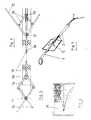
- the device shown in FIGS. 1 to 6consists essentially of the probe 1, which is arranged displaceably in a sleeve 2. The movement is facilitated by the handle holes 3 and 4.
- the sleeve 2is formed at one end, namely in the area of the display device as a writing plate 5, on which scales 6, 7 and 8 are applied in cm division.
- the sleeve 2is placed on the cervix 9 and the probe 1 is inserted up to the fundus roof 10.
- the length of the uterine cavitycan then be read off on scale 6. If desired, this can also be done on the scale 11, provided that a pointer is attached to the probe 1 in the area of the scale 11 and can be moved on the scale 11 through a slot in the sleeve 2.
- the feelers 12are used to determine the lateral extent of the uterine cavity.
- the feelers 12represent the elongated arms of a joint parallelogram designed according to the pantograph principle.
- the other two arms of the joint parallelogramare designated by 13.
- the pantographis a device for enlarging or reducing drawings, plans, diagrams and the like. It consists of a joint pair rallelogram, one point (pole) of which is recorded. The drawing to be enlarged is traversed with a point on an arm of the joint parallelogram. A point on another extended arm of the joint parallelogram then provides the same drawing on an enlarged scale. Downsizing is also possible.
- the inventionmakes use of this principle, with the difference that no enlargement or reduction of the original, i. H. the expansion of the uterine cavity is sought, although this would be possible. Rather, the course of the lateral contours of the cavum uteri obtained with the pantograph-like joint parallelogram from the feelers 12 and the arms 13 is transferred to the display device on the same scale, in that it is also designed as a pantograph-like joint parallelogram.
- the display devicetherefore consists of the arms 14, which have the same length as the feeler 12, and at the ends of which marker pins 15 are attached.
- the other two arms of the joint parallelogram of the display deviceare designated 16.
- Each joint parallelogramis attached to the probe 1 with one joint, the pole. These poles are uniformly designated 17.
- the joints of the joint parallelograms opposite the poles 17are denoted uniformly by 18.
- the joints 18are connected to one another by a transmission rod 19. It is readily apparent that the function of the poles 17 is interchangeable with that of the joints 18.
- a spring 20acts on the arms 14 of the display device and tries to spread them apart. Since this spreading is also impressed on the sensors 12 by means of the transmission rod 19, these have the tendency to also spread out.
- the feelers 12therefore lie against the lateral walls of the uterine cavity. Depending on how deep the probe 1 is inserted, the sensors spread more or less far. The spreading of the arms 14 or display device runs accordingly.
- the scum 7 and 8can therefore be used to measure the uterine cavity in a punctiform manner.
- a paper 21 provided with graduationsis clamped onto the writing plate 5.
- the marking pencils 15draw the lateral contours of the uterine cavity in one go on this paper. This is shown in Fig. 6.
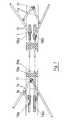
- FIG. 7shows a basic illustration of an embodiment of the device according to the invention, which also makes it possible to measure an asymmetrical profile of the lateral contours of the uterine cavity.
- the numbering of the parts from FIGS. 1 to 6has been retained.
- the function of the poles 17 and the joints 18is reversed, which option has already been mentioned above.
- thisis irrelevant to the suitability of the device for measuring asymmetrical lateral contours of the uterine cavity.
- the decisive factoris rather the division of the joints 18 into separate joints 18a and 18b, which are connected to one another by separate transmission rods 19a and 19b.
- Each sensor 12therefore spreads independently of the other sensor, insofar as the respective lateral contour of the cavum uteri allows it.
- the arms 14 of the display deviceare spread accordingly.
Landscapes
- Health & Medical Sciences (AREA)
- Life Sciences & Earth Sciences (AREA)
- Surgery (AREA)
- Physics & Mathematics (AREA)
- Animal Behavior & Ethology (AREA)
- General Health & Medical Sciences (AREA)
- Public Health (AREA)
- Engineering & Computer Science (AREA)
- Biomedical Technology (AREA)
- Heart & Thoracic Surgery (AREA)
- Medical Informatics (AREA)
- Molecular Biology (AREA)
- Veterinary Medicine (AREA)
- Pathology (AREA)
- Biophysics (AREA)
- Oral & Maxillofacial Surgery (AREA)
- Dentistry (AREA)
- General Physics & Mathematics (AREA)
- Gynecology & Obstetrics (AREA)
- Pregnancy & Childbirth (AREA)
- Reproductive Health (AREA)
- Nuclear Medicine, Radiotherapy & Molecular Imaging (AREA)
- Measurement Of The Respiration, Hearing Ability, Form, And Blood Characteristics Of Living Organisms (AREA)
- Measuring And Recording Apparatus For Diagnosis (AREA)
Description
Translated fromGermanDie Erfindung betrifft eine Vorrichtung zum Bestimmen der Innenmaße des Cavum uteri, bestehend aus einer in einer Hülse verschiebbaren Sonde, an deren Spitze bis zur Berührung mit der uteruswand aufspreizbare Fühler angeordnet sind, und bei der die Größe der Aufspreizung durch ein mechanisches Mittel zu einer am Fuß der Sonde befindlichen Anzeigevorrichtung übertragen wird.The invention relates to a device for determining the internal dimensions of the uterine cavity, consisting of a probe displaceable in a sleeve, at the tip of which expandable sensors are arranged up to the point of contact with the uterus wall, and in which the size of the spreading by a mechanical means to a Display device located foot of the probe is transmitted.
Vorrichtungen dieser Art sind beispielsweise aus der DE-OS 27 56 427 bekannt. Eine möglichst exakte Bestimmung der Innenmaß des Cavum uteri, und zwar sowohl der seitlichen Ausdehnung als auch der Länge, ist unerläßlich vor dem Einsetzen intrauteriner Antikonzeptiva, bzw. Pessare. Die Pessare müssen den inneren Abmessungen des Cavum uteri angepaßt werden, andernfalls können sie unwirksam sein oder Komplikationen der verschiedensten Art verursachen. Davon abgesehen gibt es noch eine Vielzahl weiterer Gründe, die eine genaue Bestimmung der Innenmaße des Cavum uteri wünschenswert machen.Devices of this type are known for example from DE-OS 27 56 427. A precise determination of the internal dimension of the uterine cavity, both the lateral extent and the length, is essential before the use of intrauterine contraceptives or pessaries. The pessaries must be adapted to the internal dimensions of the uterine cavity, otherwise they can be ineffective or cause complications of all kinds. That being said, there are a number of other reasons that make it desirable to determine the internal dimensions of the uterine cavity.
Mit der Vorrichtung gemäß der DE-OS 27 56 427 läßt sich diese Bestimmung zufriedenstellend bewerkstelligen. Sofern jedoch nicht nur der Abstand zwischen den beiden internen Tubenostien im Bereich des Fundusdaches ermittelt werden soll, sondern die tatsächliche Ausdehnung des gesamten Hohlraumes, ist eine Vielzahl von Einzelmessungen erforderlich, was zeitraubend ist. Darüber hinaus läßt sich ein Abbild des Hohlraumes nur unter der Voraussetzung ermitteln, daß er symmetrisch ist. Ferner hat sich gezeigt, daß bei der bekannten Vorrichtung der zur Übertragung des Maßes der Aufspreizung der Fühler zur Anzeigevorrichtung verwendete Faden nicht unproblematisch ist hinsichtlich einer ausreichend sterilen Handhabung.With the device according to DE-OS 27 56 427 this determination can be carried out satisfactorily. However, if not only the distance between the two internal tube ostia in the area of the fundus roof is to be determined, but the actual extent of the entire cavity, a large number of individual measurements are required, which is time-consuming. In addition, an image of the cavity can only be determined on the condition that it is symmetrical. Furthermore, it has been shown that in the known device the thread used to transmit the extent of the spreading of the sensors to the display device is not without problems with regard to a sufficiently sterile handling.
Der Erfindung liegt daher die Aufgabe zugrunde, eine Vorrichtung zum Bestimmen der Innenmaße des Cavum uteri zu schaffen, mit der mittels einer einzigen Messung die seitlichen Konturen des Hohlraumes ermittelt werden können. In ihrer Weiterbildung soll es die Erfindung auch ermögliche, unsymmetrische Verläufe der seitlichen Konturen des Hohlraumes zu bestimmen. Darüber hinaus soll eine sterile Handhabung der Vorrichtung gewährleistet sein, ohne daß es dazu eines zusätzlichen Aufwandes bedarf.The invention is therefore based on the object of providing a device for determining the internal dimensions of the uterine cavity with which the lateral contours of the cavity can be determined by means of a single measurement. In its development, the invention should also make it possible to determine asymmetrical profiles of the lateral contours of the cavity. In addition, sterile handling of the device is to be ensured without requiring additional effort.
Ausgehend von dem im Oberbegriff des Anspruches berücksichtigten Stand der Technik ist diese Aufgabe erfindungsgemäß gelöst mit den im kennzeichnenden Teil des Anspruches 1 angegebenen Maßnahmen.Starting from the prior art considered in the preamble of the claim, this object is achieved according to the invention with the measures specified in the characterizing part of
Vorteilhafte Weiterbildungen der Erfindung sind in den Unteransprüchen angegeben.Advantageous developments of the invention are specified in the subclaims.
Die erfindungsgemäße Vorrichtung enthält nur leicht steril zu haltende mechanische Teile. Insbesondere die Ausbildungsform gemäß Anspruch 5 ermöglicht eine sichere sterile Handhabung.The device according to the invention only contains mechanical parts that are easy to keep sterile. In particular, the form of training according to
Bei der erfindungsgemäßen Vorrichtung wird die jeweilige Aufspreizung der Fühler in eine entsprechende Aufspreizung der Arme der Anzeigevorrichtung transformiert, so daß mit einem einzigen Durchfahren der Meßvorrichtung in Längsrichtung der gesamte Verlauf der seitlichen Konturen des Cavum uteri nach außen übertragen wird. Besonders vorteilhaft ist hierbei die Ausführungsform gemäß Anspruch 4, mit der eine grafische Aufzeichnung dieses Verlaufes erhalten werden kann.In the device according to the invention, the respective spreading of the sensors is transformed into a corresponding spreading of the arms of the display device, so that the entire course of the lateral contours of the cavum uteri is transmitted to the outside with a single passage of the measuring device in the longitudinal direction. The embodiment according to
Die Abwandlung der erfindungsgemäßen Vorrichtung gemaß Anspruch 2 ermöglicht es, auch einen unsymmetrischen Verlauf der seitlichen Konturen des Cavum uteri zu bestimmen.The modification of the device according to the invention according to
Zwei Ausführungsbeispiele der Erfindung sollen anhand der beigefügten Zeichnungen erläutert werden.Two embodiments of the invention will be explained with reference to the accompanying drawings.
Es zeigen :
Figur 1 eine erfindungsgemäße Vorrichtung in perspektivischer Darstellung,Figur 2 eine seitliche Ansicht der Fig. 1 im Schnitt,- Figur eine Draufsicht der Fig. 1 im Schnitt,
Figur 4 das Gelenkparallelogramm der Fühler von Fig. 1 im Detail,Figur 5 das Gelenkparallelogramm der Anzeigevorrichtung von Fig. 1 im Detail,- Figur 6 die mit der Anzeigevorrichtung von Fig. 1 erhaltene grafische Darstellung und
Figur 7 eine Ausführungsform der Erfindung, mit welcher auch ein unsymmetrischer Verlauf der seitlichen Konturen des Cavum uteri ermittelt werden kann.
- FIG. 1 shows a device according to the invention in a perspective view,
- 2 shows a side view of FIG. 1 in section,
- 1 shows a plan view of FIG. 1 in section,
- FIG. 4 shows the joint parallelogram of the sensors of FIG. 1 in detail,
- FIG. 5 shows the joint parallelogram of the display device from FIG. 1 in detail,
- 6 shows the graphic representation obtained with the display device of FIG. 1 and
- FIG. 7 shows an embodiment of the invention with which an asymmetrical profile of the lateral contours of the uterine cavity can also be determined.
Die in den Fig. 1 bis 6 dargestellte Vorrichtung besteht im wesentlichen aus der Sonde 1, die in einer Hülse 2 verschiebbar angeordnet ist. Die Verschiebung wird durch die Grifflöcher 3 und 4 erleichtert.The device shown in FIGS. 1 to 6 consists essentially of the
Die Hülse 2 ist an einem Ende, nämlich im Bereich der Anzeigevorrichtung als Schreibplatte 5 ausgebildet, auf der Skalen 6, 7 und 8 in cm-Einteilung aufgebracht sind.The
Zur Bestimmung der Länge des Cavum uteri wird die Hülse 2 am Muttermund 9 angesetzt und die Sonde 1 bis zum Fundusdach 10 eingeführt. Die Länge des Cavum uteri kann dann an der Skala 6 abgelesen werden. Falls gewünscht, kann dies auch an der Skala 11 erfolgen, sofern auf der Sonde 1 im Bereich der Skala 11 ein Zeiger befestigt ist, der durch einen Schlitz in der Hülse 2 auf der Skala 11 verschiebbar ist.To determine the length of the uterine cavity, the
Zur Bestimmung der seitlichen Ausdehnung des Cavum uteri dienen die Fühler 12. Die Fühler 12 stellen die verlängerten Arme eines nach dem Prinzip des Pantografen ausgebildeten Gelenkparallelogramms dar. Mit 13 sind die beiden weiteren Arme des Gelenkparallelogramms bezeichnet.The
Der Pantograf ist ein Gerät, um Zeichnungen, Pläne, Diagramme und dergl. zu vergrößern oder zu verkleinern. Er besteht aus einem Gelenkparallelogramm, dessen einer Punkt (Pol) festgehalten wird. Die zu vergrößernde Zeichnung wird mit einem Punkt eines Armes des Gelenkparallelogramms abgefahren. Ein Punkt auf einem anderen verlängerten Arm des Gelenkparallelogramms liefert dann die gleiche Zeichnung im vergrößerten Maßstab. Verkleinerungen sind sinngemäß ebenfalls möglich.The pantograph is a device for enlarging or reducing drawings, plans, diagrams and the like. It consists of a joint pair rallelogram, one point (pole) of which is recorded. The drawing to be enlarged is traversed with a point on an arm of the joint parallelogram. A point on another extended arm of the joint parallelogram then provides the same drawing on an enlarged scale. Downsizing is also possible.
Die Erfindung macht von diesem Prinzip Gebrauch, jedoch mit dem Unterschied, daß keine Vergrößerung oder Verkleinerung der Vorlage, d. h. der Ausdehnung des Cavum uteri angestrebt wird, obwohl dies möglich wäre. Es wird vielmehr der mit dem pantografenähnlichen Gelenkparallelogramms aus den Fühlern 12 und den Armen 13 gewonnene Verlauf der seitlichen Konturen des Cavum uteri in gleichem Maßstab auf die Anzeigevorrichtung übertragen, indem diese ebenfalls als pantografenähnliches Gelenkparallelogramm ausgebildet ist.The invention makes use of this principle, with the difference that no enlargement or reduction of the original, i. H. the expansion of the uterine cavity is sought, although this would be possible. Rather, the course of the lateral contours of the cavum uteri obtained with the pantograph-like joint parallelogram from the
Die Anzeigevorrichtung besteht demnach aus den Armen 14, die die gleiche Länge wie die Fühler 12 besitzen, und an deren Enden Markierungsstifte 15 angebracht sind. Die beiden anderen Arme des Gelenkparallelogramms der Anzeigevorrichtung sind mit 16 bezeichnet.The display device therefore consists of the
Jedes Gelenkparallelogramm ist mit einem Gelenk, dem Pol, auf der Sonde 1 befestigt. Diese Pole sind einheitlich mit 17 bezeichnet. Die den Polen 17 gegenüberliegenden Gelenke der Gelenkparallelogramme sind einheitlich mit 18 bezeichnet. Zwecks Übertragung der Aufspreizung der Fühler 12 auf die Arme 14 der Anzeigevorrichtung sind gemäß der Erfindung die Gelenke 18 durch eine Übertragungsstange 19 miteinanderverbunden. Es ist ohne weiteres ersichtlich, daß die Funktion der Pole 17 mit der der Gelenke 18 austauschbar ist.Each joint parallelogram is attached to the
An die Arme 14 der Anzeigevorrichtung greift eine Feder 20 an, die sie auseinanderzuspreizen sucht. Da diese Aufspreizung mittels der Übertragungsstange 19 auch den Fühlern 12 aufgeprägt wird, haben diese die Tendenz, sich ebenfalls aufzuspreizen. Die Fühler 12 legen sich daher an die seitlichen Wände des Cavum uteri an. Je nachdem, wie tief die Sonde 1 eingefahren ist, spreizen sich die Fühler mehr oder weniger weit auf. Entsprechend verläuft die Aufspreizung der Arme 14 oder Anzeigevorrichtung. Mittels der Skalen 7 und 8 kann daher das Cavum uteri punktförmig ausgemessen werden. Vorzugsweise wird jedoch auf die Schreibplatte 5 ein mit Skaleneinteilung versehenes Papier 21 aufgespannt. Auf diesem Papier zeichnen die Markierungsstifte 15 in einem Zug die seitlichen Konturen des Cavum uteri. Dies ist in Fig. 6 dargestellt.A
Die Fig. 7 zeigt in prinzipieller Darstellung eine Ausführungsform der erfindungsgemäßen Vorrichtung, die es gestattet, auch einen unsymmetrischen Verlauf der seitlichen Konturen des Cavum uteri auszumessen. Die Numerierung der Teile aus den Fig. 1 bis 6 wurde beibehalten. Gegensatz zur Ausführungsform gemäß den Fig. 1 bis 6 ist hierbei die Funktion der Pole 17 und der Gelenke 18 vertauscht, auf welche Möglichkeit bereits oben hingewiesen wurde. Für die Eignung der Vorrichtung zur Ausmessung unsymmetrischer seitlicher Konturen des Cavum uteri ist dies aber unerheblich. Entscheidend ist vielmehr die Aufteilung der Gelenke 18 in separate Gelenke 18a und 18b, die durch separate Übertragungsstangen 19a und 19b miteinander verbunden sind. Jeder Fühler 12 spreizt sich daher unabhängig vom anderen Fühler auf, soweit es die jeweilige seitliche Kontur des Cavum uteri gestattet. Entsprechend erfolgt die Aufspreizung der Arme 14 der Anzeigevorrichtung.FIG. 7 shows a basic illustration of an embodiment of the device according to the invention, which also makes it possible to measure an asymmetrical profile of the lateral contours of the uterine cavity. The numbering of the parts from FIGS. 1 to 6 has been retained. In contrast to the embodiment according to FIGS. 1 to 6, the function of the
Claims (5)
Priority Applications (2)
| Application Number | Priority Date | Filing Date | Title |
|---|---|---|---|
| EP19800104410EP0044877B1 (en) | 1980-07-26 | 1980-07-26 | Device for determining the internal dimensions of the uterine cavity |
| DE8080104410TDE3070268D1 (en) | 1980-07-26 | 1980-07-26 | Device for determining the internal dimensions of the uterine cavity |
Applications Claiming Priority (1)
| Application Number | Priority Date | Filing Date | Title |
|---|---|---|---|
| EP19800104410EP0044877B1 (en) | 1980-07-26 | 1980-07-26 | Device for determining the internal dimensions of the uterine cavity |
Publications (2)
| Publication Number | Publication Date |
|---|---|
| EP0044877A1 EP0044877A1 (en) | 1982-02-03 |
| EP0044877B1true EP0044877B1 (en) | 1985-03-13 |
Family
ID=8186730
Family Applications (1)
| Application Number | Title | Priority Date | Filing Date |
|---|---|---|---|
| EP19800104410ExpiredEP0044877B1 (en) | 1980-07-26 | 1980-07-26 | Device for determining the internal dimensions of the uterine cavity |
Country Status (2)
| Country | Link |
|---|---|
| EP (1) | EP0044877B1 (en) |
| DE (1) | DE3070268D1 (en) |
Cited By (17)
| Publication number | Priority date | Publication date | Assignee | Title |
|---|---|---|---|---|
| US7621950B1 (en) | 1999-01-27 | 2009-11-24 | Kyphon Sarl | Expandable intervertebral spacer |
| US8025656B2 (en) | 2006-11-07 | 2011-09-27 | Hologic, Inc. | Methods, systems and devices for performing gynecological procedures |
| US8066713B2 (en) | 2003-03-31 | 2011-11-29 | Depuy Spine, Inc. | Remotely-activated vertebroplasty injection device |
| US8361078B2 (en) | 2003-06-17 | 2013-01-29 | Depuy Spine, Inc. | Methods, materials and apparatus for treating bone and other tissue |
| US8360629B2 (en) | 2005-11-22 | 2013-01-29 | Depuy Spine, Inc. | Mixing apparatus having central and planetary mixing elements |
| US8415407B2 (en) | 2004-03-21 | 2013-04-09 | Depuy Spine, Inc. | Methods, materials, and apparatus for treating bone and other tissue |
| US8528563B2 (en) | 2007-04-06 | 2013-09-10 | Hologic, Inc. | Systems, methods and devices for performing gynecological procedures |
| US8574253B2 (en) | 2007-04-06 | 2013-11-05 | Hologic, Inc. | Method, system and device for tissue removal |
| US8579908B2 (en) | 2003-09-26 | 2013-11-12 | DePuy Synthes Products, LLC. | Device for delivering viscous material |
| US8647349B2 (en) | 2006-10-18 | 2014-02-11 | Hologic, Inc. | Systems for performing gynecological procedures with mechanical distension |
| US8728160B2 (en) | 1999-01-27 | 2014-05-20 | Warsaw Orthopedic, Inc. | Expandable intervertebral spacer |
| KR101466707B1 (en) | 2013-10-08 | 2014-12-01 | 한국과학기술연구원 | Appratus and Method for parallel scanning guide of Optical Coherence Tomography edoscopic probe |
| US8950929B2 (en) | 2006-10-19 | 2015-02-10 | DePuy Synthes Products, LLC | Fluid delivery system |
| US8951274B2 (en) | 2007-04-06 | 2015-02-10 | Hologic, Inc. | Methods of high rate, low profile tissue removal |
| US9095366B2 (en) | 2007-04-06 | 2015-08-04 | Hologic, Inc. | Tissue cutter with differential hardness |
| US9381024B2 (en) | 2005-07-31 | 2016-07-05 | DePuy Synthes Products, Inc. | Marked tools |
| US9392935B2 (en) | 2006-11-07 | 2016-07-19 | Hologic, Inc. | Methods for performing a medical procedure |
Families Citing this family (11)
| Publication number | Priority date | Publication date | Assignee | Title |
|---|---|---|---|---|
| US4489732A (en)* | 1982-09-20 | 1984-12-25 | Hasson Harrith M | Gynecological instrument |
| FR2543834B1 (en)* | 1983-04-07 | 1985-08-23 | Descartes Universite Rene | VARIABLE GEOMETRY PROBE FOR MEASURING RADIAL CONSTRAINTS IN A SPHINCTER OF A LIVING ORGANISM |
| DE3330921C1 (en)* | 1983-08-27 | 1985-02-07 | Karl-Heinz Dr.med. 4000 Düsseldorf Kurz | Device for determining the internal mass of hollow organs, especially the uterine cavity |
| GB2162751B (en)* | 1984-08-06 | 1987-10-21 | Maurice Roger Pope | Uterine sound |
| NL9201118A (en)* | 1992-06-24 | 1994-01-17 | Leuven K U Res & Dev | TOOL KIT FOR LAPAROSCOPIC VAGINAL HYSTERECTOMY. |
| DE4303274C2 (en)* | 1993-02-05 | 1997-02-06 | Wolf Gmbh Richard | Endoscopic instrument |
| ES2545328T3 (en) | 2003-03-14 | 2015-09-10 | Depuy Spine, Inc. | Bone cement hydraulic injection device in percutaneous vertebroplasty |
| US9918767B2 (en) | 2005-08-01 | 2018-03-20 | DePuy Synthes Products, Inc. | Temperature control system |
| AU2007297097A1 (en) | 2006-09-14 | 2008-03-20 | Depuy Spine, Inc. | Bone cement and methods of use thereof |
| US11903602B2 (en) | 2009-04-29 | 2024-02-20 | Hologic, Inc. | Uterine fibroid tissue removal device |
| CN103356270B (en)* | 2013-06-28 | 2016-04-27 | 苏州联科盛世科技有限公司 | Disposable visual uterine cavity suction tube |
Family Cites Families (4)
| Publication number | Priority date | Publication date | Assignee | Title |
|---|---|---|---|---|
| DE78155C (en)* | F. W. HAVILAND, New-York | Tool for the graphic reproduction of cavities in human and animal bodies | ||
| DE597749C (en)* | 1931-03-08 | 1934-05-30 | Hilde Marcus | Device for recording spatial curves, in particular body lines |
| GB1573911A (en)* | 1976-01-08 | 1980-08-28 | Nat Res Dev | Medical instruments for estimation of cervical dilutation |
| DE2756427A1 (en)* | 1977-12-17 | 1979-06-21 | Kurz Karl Heinz | Body cavity measuring probe - has thread stretched across two retractable sensing arms giving required measurement in extended position |
- 1980
- 1980-07-26EPEP19800104410patent/EP0044877B1/ennot_activeExpired
- 1980-07-26DEDE8080104410Tpatent/DE3070268D1/ennot_activeExpired
Cited By (27)
| Publication number | Priority date | Publication date | Assignee | Title |
|---|---|---|---|---|
| US8728160B2 (en) | 1999-01-27 | 2014-05-20 | Warsaw Orthopedic, Inc. | Expandable intervertebral spacer |
| US7621950B1 (en) | 1999-01-27 | 2009-11-24 | Kyphon Sarl | Expandable intervertebral spacer |
| US8066713B2 (en) | 2003-03-31 | 2011-11-29 | Depuy Spine, Inc. | Remotely-activated vertebroplasty injection device |
| US8333773B2 (en) | 2003-03-31 | 2012-12-18 | Depuy Spine, Inc. | Remotely-activated vertebroplasty injection device |
| US8540722B2 (en) | 2003-06-17 | 2013-09-24 | DePuy Synthes Products, LLC | Methods, materials and apparatus for treating bone and other tissue |
| US8361078B2 (en) | 2003-06-17 | 2013-01-29 | Depuy Spine, Inc. | Methods, materials and apparatus for treating bone and other tissue |
| US10111697B2 (en) | 2003-09-26 | 2018-10-30 | DePuy Synthes Products, Inc. | Device for delivering viscous material |
| US8579908B2 (en) | 2003-09-26 | 2013-11-12 | DePuy Synthes Products, LLC. | Device for delivering viscous material |
| US8415407B2 (en) | 2004-03-21 | 2013-04-09 | Depuy Spine, Inc. | Methods, materials, and apparatus for treating bone and other tissue |
| US9381024B2 (en) | 2005-07-31 | 2016-07-05 | DePuy Synthes Products, Inc. | Marked tools |
| US8360629B2 (en) | 2005-11-22 | 2013-01-29 | Depuy Spine, Inc. | Mixing apparatus having central and planetary mixing elements |
| US8840625B2 (en) | 2006-10-18 | 2014-09-23 | Hologic, Inc. | Systems for performing gynecological procedures with closed visualization lumen |
| US8647349B2 (en) | 2006-10-18 | 2014-02-11 | Hologic, Inc. | Systems for performing gynecological procedures with mechanical distension |
| US8834487B2 (en) | 2006-10-18 | 2014-09-16 | Hologic, Inc. | Systems and methods for preventing intravasation during intrauterine procedures |
| US8840626B2 (en) | 2006-10-18 | 2014-09-23 | Hologic, Inc. | Systems for performing gynecological procedures with simultaneous tissue cutting and removal |
| US8950929B2 (en) | 2006-10-19 | 2015-02-10 | DePuy Synthes Products, LLC | Fluid delivery system |
| US9392935B2 (en) | 2006-11-07 | 2016-07-19 | Hologic, Inc. | Methods for performing a medical procedure |
| US8025656B2 (en) | 2006-11-07 | 2011-09-27 | Hologic, Inc. | Methods, systems and devices for performing gynecological procedures |
| US8574253B2 (en) | 2007-04-06 | 2013-11-05 | Hologic, Inc. | Method, system and device for tissue removal |
| US8951274B2 (en) | 2007-04-06 | 2015-02-10 | Hologic, Inc. | Methods of high rate, low profile tissue removal |
| US9095366B2 (en) | 2007-04-06 | 2015-08-04 | Hologic, Inc. | Tissue cutter with differential hardness |
| US9259233B2 (en) | 2007-04-06 | 2016-02-16 | Hologic, Inc. | Method and device for distending a gynecological cavity |
| US9301770B2 (en) | 2007-04-06 | 2016-04-05 | Hologic, Inc. | Systems, methods and devices for performing gynecological procedures |
| US9339288B2 (en) | 2007-04-06 | 2016-05-17 | Hologic, Inc. | Uterine fibroid tissue removal device |
| US8528563B2 (en) | 2007-04-06 | 2013-09-10 | Hologic, Inc. | Systems, methods and devices for performing gynecological procedures |
| US9539019B2 (en) | 2007-04-06 | 2017-01-10 | Hologic, Inc. | Uterine fibroid tissue removal device |
| KR101466707B1 (en) | 2013-10-08 | 2014-12-01 | 한국과학기술연구원 | Appratus and Method for parallel scanning guide of Optical Coherence Tomography edoscopic probe |
Also Published As
| Publication number | Publication date |
|---|---|
| DE3070268D1 (en) | 1985-04-18 |
| EP0044877A1 (en) | 1982-02-03 |
Similar Documents
| Publication | Publication Date | Title |
|---|---|---|
| EP0044877B1 (en) | Device for determining the internal dimensions of the uterine cavity | |
| DE2718545C2 (en) | Straightening device for straightening and reforming vehicles | |
| DE2633379B2 (en) | Device for measuring the geometry of the mold cavity of continuous casting molds | |
| DE3103163A1 (en) | MEASURING DEVICE FOR DETERMINING THE STRENGTH OF TISSUES | |
| DE4139309A1 (en) | Measuring dimensions of hollow bodies, esp. pipes - using fixed and movable parts with sensing arms with stops image separation measured when applied to pipe | |
| DE1473860A1 (en) | Coordinate measuring device, in particular for machine tools | |
| DE921358C (en) | Taper measuring device | |
| DE1139686B (en) | Device for the physical determination of three parameters on bird eggs | |
| DE3204935A1 (en) | Device for measuring the diameter of bores | |
| DE1905727C (en) | Device for distance measurement in ultrasonic testing, in particular for measuring the depth of defects or wall thickness of heavy forgings, hollow bodies, etc. | |
| DE338635C (en) | Teaching for taper pins | |
| CH681181A5 (en) | ||
| DE283705C (en) | ||
| DE2634045A1 (en) | Slide caliper for measuring thread diameters - uses split circular jaws which are adjusted by vernier slider | |
| DE1276933B (en) | Device for determining rock movements running transversely to a borehole | |
| DE8203847U1 (en) | Device for measuring the diameter of bores | |
| DE1648570C (en) | Extensometer with two plates that can be moved elastically relative to each other | |
| DE124567C (en) | ||
| DE1063392B (en) | Ruler that can be used as a compass | |
| DE174751C (en) | ||
| DE3215546A1 (en) | Circular tape measure, a measuring, drawing and calculating instrument | |
| DE3020662A1 (en) | Gynaecological intra-uterine probe - has wing-formed sleeve and foreshortening rod operated by bush-button actuated rotary cam | |
| DE1914490A1 (en) | Parallel drawing device for drawing parallel lines such as streets, paths, railways, etc. | |
| DE3151564A1 (en) | Spring-measuring and spring-testing device | |
| CH316795A (en) | Callipers for direct reading of the distance between two workpiece locations |
Legal Events
| Date | Code | Title | Description |
|---|---|---|---|
| PUAI | Public reference made under article 153(3) epc to a published international application that has entered the european phase | Free format text:ORIGINAL CODE: 0009012 | |
| AK | Designated contracting states | Designated state(s):DE FR GB NL | |
| 17P | Request for examination filed | Effective date:19820907 | |
| GRAA | (expected) grant | Free format text:ORIGINAL CODE: 0009210 | |
| AK | Designated contracting states | Designated state(s):DE FR GB NL | |
| PG25 | Lapsed in a contracting state [announced via postgrant information from national office to epo] | Ref country code:NL Effective date:19850313 Ref country code:FR Free format text:THE PATENT HAS BEEN ANNULLED BY A DECISION OF A NATIONAL AUTHORITY Effective date:19850313 | |
| REF | Corresponds to: | Ref document number:3070268 Country of ref document:DE Date of ref document:19850418 | |
| NLV1 | Nl: lapsed or annulled due to failure to fulfill the requirements of art. 29p and 29m of the patents act | ||
| EN | Fr: translation not filed | ||
| PLBE | No opposition filed within time limit | Free format text:ORIGINAL CODE: 0009261 | |
| STAA | Information on the status of an ep patent application or granted ep patent | Free format text:STATUS: NO OPPOSITION FILED WITHIN TIME LIMIT | |
| GBPC | Gb: european patent ceased through non-payment of renewal fee | ||
| 26N | No opposition filed | ||
| PG25 | Lapsed in a contracting state [announced via postgrant information from national office to epo] | Ref country code:DE Effective date:19860401 | |
| PG25 | Lapsed in a contracting state [announced via postgrant information from national office to epo] | Ref country code:GB Effective date:19881118 |