EP0042301B1 - Ceramic honeycomb filters and the production thereof - Google Patents
Ceramic honeycomb filters and the production thereofDownload PDFInfo
- Publication number
- EP0042301B1 EP0042301B1EP81302703AEP81302703AEP0042301B1EP 0042301 B1EP0042301 B1EP 0042301B1EP 81302703 AEP81302703 AEP 81302703AEP 81302703 AEP81302703 AEP 81302703AEP 0042301 B1EP0042301 B1EP 0042301B1
- Authority
- EP
- European Patent Office
- Prior art keywords
- face
- ceramic honeycomb
- sealing
- channels
- ceramic
- Prior art date
- Legal status (The legal status is an assumption and is not a legal conclusion. Google has not performed a legal analysis and makes no representation as to the accuracy of the status listed.)
- Expired
Links
- 239000000919ceramicSubstances0.000titleclaimsdescription74
- 238000004519manufacturing processMethods0.000titleclaimsdescription5
- 238000007789sealingMethods0.000claimsdescription95
- 238000001125extrusionMethods0.000claimsdescription15
- 239000000853adhesiveSubstances0.000claimsdescription14
- 230000001070adhesive effectEffects0.000claimsdescription14
- 239000000463materialSubstances0.000claimsdescription11
- 238000000034methodMethods0.000claimsdescription11
- 229910010293ceramic materialInorganic materials0.000claimsdescription10
- 239000011521glassSubstances0.000claimsdescription5
- 239000007789gasSubstances0.000description12
- 238000005192partitionMethods0.000description11
- 239000000203mixtureSubstances0.000description9
- KZHJGOXRZJKJNY-UHFFFAOYSA-Ndioxosilane;oxo(oxoalumanyloxy)alumaneChemical compoundO=[Si]=O.O=[Si]=O.O=[Al]O[Al]=O.O=[Al]O[Al]=O.O=[Al]O[Al]=OKZHJGOXRZJKJNY-UHFFFAOYSA-N0.000description7
- 229910052863mulliteInorganic materials0.000description7
- PNEYBMLMFCGWSK-UHFFFAOYSA-Naluminium oxideInorganic materials[O-2].[O-2].[O-2].[Al+3].[Al+3]PNEYBMLMFCGWSK-UHFFFAOYSA-N0.000description5
- 239000010419fine particleSubstances0.000description5
- 239000002994raw materialSubstances0.000description5
- RKTYLMNFRDHKIL-UHFFFAOYSA-Ncopper;5,10,15,20-tetraphenylporphyrin-22,24-diideChemical compound[Cu+2].C1=CC(C(=C2C=CC([N-]2)=C(C=2C=CC=CC=2)C=2C=CC(N=2)=C(C=2C=CC=CC=2)C2=CC=C3[N-]2)C=2C=CC=CC=2)=NC1=C3C1=CC=CC=C1RKTYLMNFRDHKIL-UHFFFAOYSA-N0.000description3
- 229910052878cordieriteInorganic materials0.000description3
- JSKIRARMQDRGJZ-UHFFFAOYSA-Ndimagnesium dioxido-bis[(1-oxido-3-oxo-2,4,6,8,9-pentaoxa-1,3-disila-5,7-dialuminabicyclo[3.3.1]nonan-7-yl)oxy]silaneChemical compound[Mg++].[Mg++].[O-][Si]([O-])(O[Al]1O[Al]2O[Si](=O)O[Si]([O-])(O1)O2)O[Al]1O[Al]2O[Si](=O)O[Si]([O-])(O1)O2JSKIRARMQDRGJZ-UHFFFAOYSA-N0.000description3
- 238000001914filtrationMethods0.000description3
- MWUXSHHQAYIFBG-UHFFFAOYSA-Nnitrogen oxideInorganic materialsO=[N]MWUXSHHQAYIFBG-UHFFFAOYSA-N0.000description3
- 239000011148porous materialSubstances0.000description3
- XLYOFNOQVPJJNP-UHFFFAOYSA-NwaterSubstancesOXLYOFNOQVPJJNP-UHFFFAOYSA-N0.000description3
- 229910052581Si3N4Inorganic materials0.000description2
- VYPSYNLAJGMNEJ-UHFFFAOYSA-NSilicium dioxideChemical compoundO=[Si]=OVYPSYNLAJGMNEJ-UHFFFAOYSA-N0.000description2
- MCMNRKCIXSYSNV-UHFFFAOYSA-NZirconium dioxideChemical compoundO=[Zr]=OMCMNRKCIXSYSNV-UHFFFAOYSA-N0.000description2
- 239000003054catalystSubstances0.000description2
- 239000004568cementSubstances0.000description2
- 229920000609methyl cellulosePolymers0.000description2
- 239000001923methylcelluloseSubstances0.000description2
- 235000010981methylcelluloseNutrition0.000description2
- 230000035939shockEffects0.000description2
- HBMJWWWQQXIZIP-UHFFFAOYSA-Nsilicon carbideChemical compound[Si+]#[C-]HBMJWWWQQXIZIP-UHFFFAOYSA-N0.000description2
- 229910010271silicon carbideInorganic materials0.000description2
- HQVNEWCFYHHQES-UHFFFAOYSA-Nsilicon nitrideChemical compoundN12[Si]34N5[Si]62N3[Si]51N64HQVNEWCFYHHQES-UHFFFAOYSA-N0.000description2
- 239000002002slurrySubstances0.000description2
- 239000005995Aluminium silicateSubstances0.000description1
- UGFAIRIUMAVXCW-UHFFFAOYSA-NCarbon monoxideChemical compound[O+]#[C-]UGFAIRIUMAVXCW-UHFFFAOYSA-N0.000description1
- 239000011398Portland cementSubstances0.000description1
- 229910000831SteelInorganic materials0.000description1
- 235000012211aluminium silicateNutrition0.000description1
- 239000011230binding agentSubstances0.000description1
- 230000000903blocking effectEffects0.000description1
- 229910002091carbon monoxideInorganic materials0.000description1
- 239000004927claySubstances0.000description1
- 238000002485combustion reactionMethods0.000description1
- 230000007797corrosionEffects0.000description1
- 238000005260corrosionMethods0.000description1
- 238000007598dipping methodMethods0.000description1
- 238000001035dryingMethods0.000description1
- 230000000694effectsEffects0.000description1
- 238000010304firingMethods0.000description1
- 229930195733hydrocarbonNatural products0.000description1
- 150000002430hydrocarbonsChemical class0.000description1
- NLYAJNPCOHFWQQ-UHFFFAOYSA-NkaolinChemical compoundO.O.O=[Al]O[Si](=O)O[Si](=O)O[Al]=ONLYAJNPCOHFWQQ-UHFFFAOYSA-N0.000description1
- 238000002156mixingMethods0.000description1
- 239000004014plasticizerSubstances0.000description1
- 239000000843powderSubstances0.000description1
- 238000007493shaping processMethods0.000description1
- 239000000377silicon dioxideSubstances0.000description1
- 239000010959steelSubstances0.000description1
- 239000000454talcSubstances0.000description1
- 229910052623talcInorganic materials0.000description1
- 210000002268woolAnatomy0.000description1
Images


Classifications
- C—CHEMISTRY; METALLURGY
- C04—CEMENTS; CONCRETE; ARTIFICIAL STONE; CERAMICS; REFRACTORIES
- C04B—LIME, MAGNESIA; SLAG; CEMENTS; COMPOSITIONS THEREOF, e.g. MORTARS, CONCRETE OR LIKE BUILDING MATERIALS; ARTIFICIAL STONE; CERAMICS; REFRACTORIES; TREATMENT OF NATURAL STONE
- C04B38/00—Porous mortars, concrete, artificial stone or ceramic ware; Preparation thereof
- C04B38/0006—Honeycomb structures
- B—PERFORMING OPERATIONS; TRANSPORTING
- B01—PHYSICAL OR CHEMICAL PROCESSES OR APPARATUS IN GENERAL
- B01D—SEPARATION
- B01D29/00—Filters with filtering elements stationary during filtration, e.g. pressure or suction filters, not covered by groups B01D24/00 - B01D27/00; Filtering elements therefor
- B01D29/11—Filters with filtering elements stationary during filtration, e.g. pressure or suction filters, not covered by groups B01D24/00 - B01D27/00; Filtering elements therefor with bag, cage, hose, tube, sleeve or like filtering elements
- B01D29/111—Making filtering elements
- B—PERFORMING OPERATIONS; TRANSPORTING
- B01—PHYSICAL OR CHEMICAL PROCESSES OR APPARATUS IN GENERAL
- B01D—SEPARATION
- B01D29/00—Filters with filtering elements stationary during filtration, e.g. pressure or suction filters, not covered by groups B01D24/00 - B01D27/00; Filtering elements therefor
- B01D29/11—Filters with filtering elements stationary during filtration, e.g. pressure or suction filters, not covered by groups B01D24/00 - B01D27/00; Filtering elements therefor with bag, cage, hose, tube, sleeve or like filtering elements
- B01D29/31—Self-supporting filtering elements
- B—PERFORMING OPERATIONS; TRANSPORTING
- B01—PHYSICAL OR CHEMICAL PROCESSES OR APPARATUS IN GENERAL
- B01D—SEPARATION
- B01D29/00—Filters with filtering elements stationary during filtration, e.g. pressure or suction filters, not covered by groups B01D24/00 - B01D27/00; Filtering elements therefor
- B01D29/50—Filters with filtering elements stationary during filtration, e.g. pressure or suction filters, not covered by groups B01D24/00 - B01D27/00; Filtering elements therefor with multiple filtering elements, characterised by their mutual disposition
- B01D29/52—Filters with filtering elements stationary during filtration, e.g. pressure or suction filters, not covered by groups B01D24/00 - B01D27/00; Filtering elements therefor with multiple filtering elements, characterised by their mutual disposition in parallel connection
- B—PERFORMING OPERATIONS; TRANSPORTING
- B01—PHYSICAL OR CHEMICAL PROCESSES OR APPARATUS IN GENERAL
- B01D—SEPARATION
- B01D46/00—Filters or filtering processes specially modified for separating dispersed particles from gases or vapours
- B01D46/24—Particle separators, e.g. dust precipitators, using rigid hollow filter bodies
- B01D46/2403—Particle separators, e.g. dust precipitators, using rigid hollow filter bodies characterised by the physical shape or structure of the filtering element
- B01D46/2407—Filter candles
- B—PERFORMING OPERATIONS; TRANSPORTING
- B28—WORKING CEMENT, CLAY, OR STONE
- B28B—SHAPING CLAY OR OTHER CERAMIC COMPOSITIONS; SHAPING SLAG; SHAPING MIXTURES CONTAINING CEMENTITIOUS MATERIAL, e.g. PLASTER
- B28B3/00—Producing shaped articles from the material by using presses; Presses specially adapted therefor
- B28B3/20—Producing shaped articles from the material by using presses; Presses specially adapted therefor wherein the material is extruded
- B28B3/26—Extrusion dies
- B28B3/269—For multi-channeled structures, e.g. honeycomb structures
- B—PERFORMING OPERATIONS; TRANSPORTING
- B01—PHYSICAL OR CHEMICAL PROCESSES OR APPARATUS IN GENERAL
- B01D—SEPARATION
- B01D2201/00—Details relating to filtering apparatus
- B01D2201/46—Several filtrate discharge conduits each connected to one filter element or group of filter elements
Definitions
- the present inventionrelates to filters, for example for removing fine particles contained in exhaust gases, and more particularly to ceramic honeycomb filters.
- filtersare disclosed in EP-A-36321 (corresponds to European patent application number 81301091.5 which claims the priority 15.03.80 YP33202/80) published on 23.9.81.
- Filtersdepend for their effect upon filter media such as steel wool, ceramic fibres, porous porcelains and the like and in filters intended to remove fine particles filter media of fine mesh or pore size have to be employed but the use of such filter media leads to an increase in pressure drop when a high filtration rate is required.
- the area of the filter.may be increased and thus in the case of the prior sheet-form, plate-form or cylindrical filters, relatively simple structures, such as a corrugated structure or a double cylindrical form are employed to increase the filter area but this does not lead to a marked increase in filter area per unit volume. Therefore, in order to avoid high pressure drop, it is necessary to use fairly large filters and it is very difficult to obtain comparatively small filters.
- Honeycomb bodieshave recently been used as catalyst supports for catalytically purifying exhaust gases in automobiles and as heat exchangers for gas turbines and the like.
- a honeycomb bodycomprises a body of a material, such as a ceramic material, having a large number of generally parallel channels extending through the body from one end face thereof to an opposite end face and separated by thin walls.
- a materialsuch as a ceramic material
- the thin partition walls defining the channelshave been used as pipes to conduct a gas therealong, for example to react with catalyst coated onto the walls to convert harmful gases, such as carbon monoxide, hydrocarbons and nitrogen oxides, in exhaust gases thereby to purify the exhaust gases.
- Such a honeycomb bodyhas a thin wall thickness and has a large surface area per unit volume and it is an object of this invention to use such a honeycomb structural body as a filter.
- a honeycomb structural bodycomposed of a porous ceramic material and having a large number of channels and sealing the other ends of the remaining channels.
- the present inventionin one aspect provides a ceramic honeycomb filter which comprises a ceramic honeycomb body having a plurality of channels extending from one end face of the body to the other end face thereof, wherein ceramic sealing members shaped by means of a press die or an extrusion die are fitted to the said end faces of the ceramic honeycomb body, which sealing members each have sealing portions, and wherein the sealing portions of one sealing member block given channels at one end face of the ceramic honeycomb body and do not block opening portions of the remaining channels at the same one end face, and the sealing portions of the other sealing member block the remaining channels at the other end face of the body and do not block opening portions of the given channels at the same other end face.
- the inventionin another aspect provides a method for producing a ceramic honeycomb filter, comprising fitting a ceramic sealing member shaped by means of a press die or an extrusion die to each of both end faces of a ceramic honeycomb main body having a plurality of channels extending from one end face to the other end face thereof, which sealing members each have sealing portions, such that the sealing portions of one sealing member block given channels at one end face of the ceramic honeycomb body and do not block opening portions of the remaining channels at the same one end face, and the sealing portions of the other sealing member block the remaining channels at the other end face of the body and do not block opening portions of the given channels at the same other end face.
- the sealing membersare adhered to each end face of the ceramic honeycomb body with an adhesive, which is preferably an organic adhesive, a glass material or a ceramic material.
- Various methodsmay be used to produce ceramic honeycomb bodies; for example a paper dipping process wherein an organic porous sheet is impregnated with a ceramic slurry and a honeycomb structural body is formed and the formed body is fired; a pipe binding process wherein a large number of pipes of given cross-section are bound or bonded together; an extrusion process wherein raw material is extruded through a die provided with a large number of given shaped slits; and a press process.
- finely powdered ceramic raw materialsuch as alumina, silica, mullite, silicon carbide, silicon nitride and/or cordierite, is mixed with an organic binder and a plasticizer.
- the mixtureis then kneaded to prepare a composition consisting mainly of ceramic raw material.
- This compositionis then extruded through a die provided with a large number of slits, which forms channels of a given cross-section, such as triangular, tetragonal or hexagonal, to form a monolithic structure, and the shaped structure is dried and fired to give a porous ceramic honeycomb body.
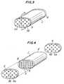
- a ceramic honeycomb filter in accordance with the inventioncomprises a ceramic honeycomb body 1 having a plurality of channels 2 extending through the body from one end face 4 to another end face 4' of the body and separated by walls 3.
- Ceramic sealing members 5 and 6shaped by means of a press die or an extrusion die, are provided with sealing portions 5A and 6A which can block the channels in the honeycomb body 1 in a checker flag pattern, and which are fitted to each of faces 4 and 4' of the honeycomb body 1, so that the sealing portions 5A of the sealing member 5 block certain given channels 2 at one face 4 of the honeycomb body and do not block opening portions of the remaining channels at the face 4, and the sealing portions 6A of the other sealing member 6 block the remaining channels 2 at the other face 4' and do not block opening portions of the given channels at the face 4'.
- Each of sealing members 5 and 6is further provided with openings 5B and 6B corresponding with channels at the end faces 4 and 4' not blocked by the sealing portions of the sealing members.
- sealing memberused herein means a member which blocks the channels of a honeycomb body with the sealing portion in a given pattern and the term “sealing portion” as used herein means the portion of the sealing member which blocks the channels.
- the present inventionutilises the thin porous partition walls 3 forming the channels as a filter by blocking the ends of the channels with the sealing portions of the sealing members.
- the sealing membersWhen the sealing members are fitted to faces of the ceramic honeycomb body which is used as a filter, it is not always necessary to adhere or bond the ceramic honeycomb body to the sealing members but in order to prevent shifting of the honeycomb body relative to the sealing members, it is preferable to bond them together by using an organic adhesive, a glass material, a ceramic material or the like.
- the pattern of the sealing portion of the sealing memberis not limited to the checker flag pattern shown in Figure 3 but may be other patterns. Similarly, it is not necessary that the channels of the ceramic honeycomb body be tetragonal in cross-section they may be triangular, hexagonal or the like.
- the cross-section shape of the ceramic honeycomb filteris not necessarily oval but may, for example, be circular or hexagonal.
- Figure 5shows a schematic cross-sectional view taken on the line V-V in Figure 3 and Figure 6 is an enlarged view of the partition wall in Figure 5.
- a gassuch as an exhaust gas
- supplied from one sideflows into certain channels 2 of the body 1 through the openings 5B in the sealing member 5 and then flows into the adjacent channels 2 through the pores 7 in the partition walls 3 and is discharged from the openings 6B of sealing member 6.
- fine particles in the gasare removed, or filtered out, .by the partition walls of the ceramic honeycomb structural main body 1.
- the ceramic honeycomb filters of the present inventionmay be manufactured from ceramic materials of various qualities and properties depending upon the intended end use of the filter. For example, when thermal shock resistance is required, cordierite, silicon nitride, silicon carbide and the like, which have a low coefficient of thermal expansion, are preferably employed, and when a very high heat resistance is required, mullite, alumina, zirconia and the like are preferably used.
- the ceramic honeycomb body and the sealing membersare usually preferred to be formed of the same material but this is not necessary, and the materials may differ depending on the intended end use of the filter.
- the ceramic honeycomb structural main bodymay be manufactured of a material having other properties.
- the filtering function of the present inventionis principally effected by the partition walls of the ceramic honeycomb body and it is not always necessary that the sealing members be of a porous material.
- a filter of the inventionis formed by first producing the ceramic honeycomb body and the sealing members in an unfired state.
- the ceramic honeycomb bodymay, as described above, be produced by an extrusion process, for example as described in United States Patent No. 3,824,196.
- the sealing membermay be produced using an extrusion die as shown in Figure 7 and Figure 8 having passages 8 to supply a batch material and orifices 9 with portions 10 of the die base material projecting therebetween so as to block the usual channels of the honeycomb structural body in the desired pattern, or a press die having the appropriate shape. Then, the shaped sealing members 5 and 6 are dried and then are cut or finished into the given size and thickness.
- the thus formed sealing members 5 and 6are appropriately positioned and the end faces 4 and 4' of the dried ceramic honeycomb body 1 are adhered thereto using, for example, a paste or slurry of the same ceramic material as used in the manufacture of the ceramic honeycomb body as an adhesive.
- the portions which serve to adhere the ceramic honeycomb body 1 to the sealing members 5 and 6are the end faces 4 and 4' of the ceramic honeycomb body 1, so that it is preferable to apply an adhesive to the end faces of the ceramic honeycomb body and, if necessary, an adhesive may be applied to one side of the sealing member.
- the adhered or bonded assemblyis then fired at an appropriate temperature to give the desired filter.
- the sealing portions 5A and 6A of the sealing members 5 and 6may be variously patterned by appropriate design of a press die or an extrusion die and, particularly when employing an extrusion die, the sealing member may be continuously manufactured.
- the sealing members shaped by using a press die or an extrusion diecan be cut or finished into the desired size at- any step of after shaping, after drying or after firing.
- the whole assemblyis fired to give a ceramic honeycomb filter, but this is not essential.
- a ceramic raw materialconsisting of 38 parts of talc, 40 parts of Kaolin and 22 parts of alumina were added 4 parts by weight of methyl cellulose and sufficient water to give a workable mixture.
- the mixturewas thoroughly kneaded and an oval honeycomb body having a short diameter of 81 mm, a long diameter of 170 mm, a length of 152 mm, a partition wall thickness of 0.30 mm and about 200/inch 2 (31/cm 2 ) channels, in cross-section, was produced therefrom by a known extrusion process.
- a first sealing member having the same outer shape as the ceramic honeycomb bodywas shaped from the same composition as used for the ceramic honeycomb body by using an extrusion die designed so that the channels at one end face of the ceramic honeycomb body are blocked with sealing portions of the sealing member in a checker flag pattern.
- a similar, second sealing member having the same outer shape as the ceramic honeycomb bodywas shaped by using an extrusion die designed so that the sealing portions of the first sealing member became openings and the openings of the first sealing member became sealing portions.
- each of the dried sealing memberswere combined, one to each end face of the ceramic honeycomb body, so that one of the sealing members blocked given channels at one end face of the honeycomb structural body and the sealing portions of the other sealing member blocked the remaining channels at the other end face.
- the ceramic honeycomb body and sealing memberwere adhered using a paste obtained by mixing a powder of the same composition as used for the ceramic honeycomb body with an appropriate amount of methyl cellulose and water and the adhered assembly was fired at a maximum temperature of 1,400°C for two hours to give a cordierite honeycomb filter having a filter area of about 16,700 cm 2 .
- the pressure drop of the filterwas measured using air at room temperature and was found to be 120 mm H 2 0 (1176 Pa) at a flow rate of 4 m 3 /min.
- a ceramic honeycomb filterwas produced following the procedure as described in Example 1 except that there was employed as ceramic raw material a mixture of 85 parts of powdered synthetic mullite (less than 250 microns) and powdered clay; the mixture was extruded to give a circular honeycomb body having a diameter of 118 mm and a length of 1 52 mm (having the same partition wall thickness and number of channels per cm 2 as that in Example 1); the sealing members had a thickness of 8 cm; and the assembly of sealing members and honeycomb body was fired at a maximum temperature of 1420°C.
- the resulting filterhad a filter area of 15,500 cm 2 and a pressure drop, measured as described in Example 1, of 100 mm H 2 0 (980 Pa) at a flow rate of 4 m 3 /min.
- a mullite honeycomb structural main body and mullite sealing members which have the same quality and shape as those prepared in Example 2were each fired and then the sealing members were arranged at the end faces of the mullite honeycomb body in the same manner as described in Example 1 and adhered and hardened using an alumina cement added with an appropriate amount of water to give a mullite honeycomb filter.
- the pressure drop of the filtermeasured as described in Example 1, was 103 mm H 2 0 (1009 Pa) at a flow rate of 4 m 3 /min, substantially the same value as in Example 2.
- the available filter area per unit volume of the ceramic honeycomb filters of the inventionis high and the partition walls can be made very thin, so that even if a high filtration rate is demanded, a relatively low pressure loss is attained, so that a compact structure can be obtained.
- the filterscan be formed of porous ceramic materials having high thermal shock resistance and heat resistance by selecting and combining the ceramic honeycomb structural main body and the sealing member, and ceramic honeycomb filters which can be used at high temperatures and are very stable to sudden temperature change can be obtained. Accordingly, the present invention provides ceramic honeycomb filters which may be used to remove fine particles from high temperature exhaust gases from diesel and other internal combustion engines.
Landscapes
- Chemical & Material Sciences (AREA)
- Engineering & Computer Science (AREA)
- Chemical Kinetics & Catalysis (AREA)
- Ceramic Engineering (AREA)
- Geometry (AREA)
- Manufacturing & Machinery (AREA)
- Physics & Mathematics (AREA)
- Mechanical Engineering (AREA)
- Materials Engineering (AREA)
- Structural Engineering (AREA)
- Organic Chemistry (AREA)
- Filtering Materials (AREA)
- Laminated Bodies (AREA)
Description
- The present invention relates to filters, for example for removing fine particles contained in exhaust gases, and more particularly to ceramic honeycomb filters. Such filters are disclosed in EP-A-36321 (corresponds to European patent application number 81301091.5 which claims the priority 15.03.80 YP33202/80) published on 23.9.81.
- Filters depend for their effect upon filter media such as steel wool, ceramic fibres, porous porcelains and the like and in filters intended to remove fine particles filter media of fine mesh or pore size have to be employed but the use of such filter media leads to an increase in pressure drop when a high filtration rate is required. To overcome this problem the area of the filter. may be increased and thus in the case of the prior sheet-form, plate-form or cylindrical filters, relatively simple structures, such as a corrugated structure or a double cylindrical form are employed to increase the filter area but this does not lead to a marked increase in filter area per unit volume. Therefore, in order to avoid high pressure drop, it is necessary to use fairly large filters and it is very difficult to obtain comparatively small filters.
- Honeycomb bodies have recently been used as catalyst supports for catalytically purifying exhaust gases in automobiles and as heat exchangers for gas turbines and the like.
- A honeycomb body comprises a body of a material, such as a ceramic material, having a large number of generally parallel channels extending through the body from one end face thereof to an opposite end face and separated by thin walls. As a result the pressure drop or resistance to gas flow is small and since the surface area per unit volume is high and the channels are defined by thin walls, the body can be heated by using only a small amount of heat. In such ceramic honeycomb bodies, the thin partition walls defining the channels have been used as pipes to conduct a gas therealong, for example to react with catalyst coated onto the walls to convert harmful gases, such as carbon monoxide, hydrocarbons and nitrogen oxides, in exhaust gases thereby to purify the exhaust gases.
- Such a honeycomb body has a thin wall thickness and has a large surface area per unit volume and it is an object of this invention to use such a honeycomb structural body as a filter. Thus, by sealing one end of given channels in a honeycomb body composed of a porous ceramic material and having a large number of channels and sealing the other ends of the remaining channels, a compact ceramic filter capable of removing fine particles and having a low pressure drop, in which the thickness of the filter is much less than that of a conventional ceramic filter and the available filter area can be enlarged, can be provided.
- The present invention in one aspect provides a ceramic honeycomb filter which comprises a ceramic honeycomb body having a plurality of channels extending from one end face of the body to the other end face thereof, wherein ceramic sealing members shaped by means of a press die or an extrusion die are fitted to the said end faces of the ceramic honeycomb body, which sealing members each have sealing portions, and wherein the sealing portions of one sealing member block given channels at one end face of the ceramic honeycomb body and do not block opening portions of the remaining channels at the same one end face, and the sealing portions of the other sealing member block the remaining channels at the other end face of the body and do not block opening portions of the given channels at the same other end face.
- The invention in another aspect provides a method for producing a ceramic honeycomb filter, comprising fitting a ceramic sealing member shaped by means of a press die or an extrusion die to each of both end faces of a ceramic honeycomb main body having a plurality of channels extending from one end face to the other end face thereof, which sealing members each have sealing portions, such that the sealing portions of one sealing member block given channels at one end face of the ceramic honeycomb body and do not block opening portions of the remaining channels at the same one end face, and the sealing portions of the other sealing member block the remaining channels at the other end face of the body and do not block opening portions of the given channels at the same other end face.
- Preferably the sealing members are adhered to each end face of the ceramic honeycomb body with an adhesive, which is preferably an organic adhesive, a glass material or a ceramic material.
- The invention will be further described, by way of example only, with reference to the accompanying drawings, wherein:
- Figure 1 is an end view of one embodiment of a honeycomb body shown in Figure 2;
- Figure 2 is a side view, partially in section, of the honeycomb body shown in Figure 1;
- Figure 3 is a perspective view of a ceramic honeycomb filter according to the present invention;
- Figure 4 is an exploded perspective view of the ceramic honeycomb filter shown in Figure 3;
- Figure 5 is a schematic cross-section taken on the line V-V in Figure 3;
- Figure 6 is an enlarged view of an essential part of a partition wall in Figure 5;
- Figure 7 is an enlarged view of an essential part of a die for extruding a sealing member; and
- Figure 8 is an enlarged cross-sectional view taken on the line VIII-VIII in Figure 7.
- Figures 1 and 2 show one embodiment of a honeycomb body 1 in which a large number of
parallel channels 2 of tetragonal cross-section extend therethrough and each channel is defined bythin partition walls 3. - Various methods may be used to produce ceramic honeycomb bodies; for example a paper dipping process wherein an organic porous sheet is impregnated with a ceramic slurry and a honeycomb structural body is formed and the formed body is fired; a pipe binding process wherein a large number of pipes of given cross-section are bound or bonded together; an extrusion process wherein raw material is extruded through a die provided with a large number of given shaped slits; and a press process. In more detail, in an extrusion process, finely powdered ceramic raw material, such as alumina, silica, mullite, silicon carbide, silicon nitride and/or cordierite, is mixed with an organic binder and a plasticizer. The mixture is then kneaded to prepare a composition consisting mainly of ceramic raw material. This composition is then extruded through a die provided with a large number of slits, which forms channels of a given cross-section, such as triangular, tetragonal or hexagonal, to form a monolithic structure, and the shaped structure is dried and fired to give a porous ceramic honeycomb body.
- As shown in Figures 3 and 4 a ceramic honeycomb filter in accordance with the invention comprises a ceramic honeycomb body 1 having a plurality of
channels 2 extending through the body from one end face 4 to another end face 4' of the body and separated bywalls 3. Ceramic sealing members portions portions 5A of the sealingmember 5 block certain givenchannels 2 at one face 4 of the honeycomb body and do not block opening portions of the remaining channels at the face 4, and the sealingportions 6A of the other sealingmember 6 block theremaining channels 2 at the other face 4' and do not block opening portions of the given channels at the face 4'. Each of sealingmembers openings - The term "sealing member" used herein means a member which blocks the channels of a honeycomb body with the sealing portion in a given pattern and the term "sealing portion" as used herein means the portion of the sealing member which blocks the channels.
- The present invention utilises the thin
porous partition walls 3 forming the channels as a filter by blocking the ends of the channels with the sealing portions of the sealing members. - When the sealing members are fitted to faces of the ceramic honeycomb body which is used as a filter, it is not always necessary to adhere or bond the ceramic honeycomb body to the sealing members but in order to prevent shifting of the honeycomb body relative to the sealing members, it is preferable to bond them together by using an organic adhesive, a glass material, a ceramic material or the like.
- The pattern of the sealing portion of the sealing member is not limited to the checker flag pattern shown in Figure 3 but may be other patterns. Similarly, it is not necessary that the channels of the ceramic honeycomb body be tetragonal in cross-section they may be triangular, hexagonal or the like.
- The cross-section shape of the ceramic honeycomb filter is not necessarily oval but may, for example, be circular or hexagonal.
- The operation of a filter according the present invention may be described by reference to Figures 5 and 6 of the drawings.
- Figure 5 shows a schematic cross-sectional view taken on the line V-V in Figure 3 and Figure 6 is an enlarged view of the partition wall in Figure 5. In the ceramic honeycomb filter,
certain channels 2 are blocked by sealingportions 5A of the sealingmember 5 at face 4 of the body and the remaining channels are blocked by sealingportions 6A of the other sealingmember 6 at face 4' of the body 1. Accordingly, a gas, such as an exhaust gas, supplied from one side flows intocertain channels 2 of the body 1 through theopenings 5B in the sealingmember 5 and then flows into theadjacent channels 2 through thepores 7 in thepartition walls 3 and is discharged from theopenings 6B of sealingmember 6. Thus, fine particles in the gas are removed, or filtered out, .by the partition walls of the ceramic honeycomb structural main body 1. - The ceramic honeycomb filters of the present invention may be manufactured from ceramic materials of various qualities and properties depending upon the intended end use of the filter. For example, when thermal shock resistance is required, cordierite, silicon nitride, silicon carbide and the like, which have a low coefficient of thermal expansion, are preferably employed, and when a very high heat resistance is required, mullite, alumina, zirconia and the like are preferably used.
- The ceramic honeycomb body and the sealing members are usually preferred to be formed of the same material but this is not necessary, and the materials may differ depending on the intended end use of the filter.
- For example, when heat resistance and corrosion resistance are required only at a position relatively near one end surface of the filter, a material having the necessary properties is used only for the sealing member and the ceramic honeycomb structural main body may be manufactured of a material having other properties. The filtering function of the present invention is principally effected by the partition walls of the ceramic honeycomb body and it is not always necessary that the sealing members be of a porous material.
- A filter of the invention is formed by first producing the ceramic honeycomb body and the sealing members in an unfired state. The ceramic honeycomb body may, as described above, be produced by an extrusion process, for example as described in United States Patent No. 3,824,196. The sealing member may be produced using an extrusion die as shown in Figure 7 and Figure 8 having
passages 8 to supply a batch material and orifices 9 withportions 10 of the die base material projecting therebetween so as to block the usual channels of the honeycomb structural body in the desired pattern, or a press die having the appropriate shape. Then, theshaped sealing members - The thus formed sealing
members members - The adhered or bonded assembly is then fired at an appropriate temperature to give the desired filter.
- The sealing
portions members - It is preferred that after the dried ceramic honeycomb body and sealing members have been bonded with an adhesive, the whole assembly is fired to give a ceramic honeycomb filter, but this is not essential.
- For example, the ceramic honeycomb body and the sealing members may each be fired at the appropriate temperature and then mechanically assembled and bonded together, or may be adhered and hardened using an organic adhesive, Portland cement or alumina cement, or fired and bonded using a glass ma= terial, or fired and bonded using the same ceramic material as used in the manufacture of the ceramic honeycomb body and the sealing members.
- The invention will be further described with reference to the following illustrative Examples. In the examples all parts are by weight unless otherwise specified.
- To 100 parts of a ceramic raw material consisting of 38 parts of talc, 40 parts of Kaolin and 22 parts of alumina were added 4 parts by weight of methyl cellulose and sufficient water to give a workable mixture. The mixture was thoroughly kneaded and an oval honeycomb body having a short diameter of 81 mm, a long diameter of 170 mm, a length of 152 mm, a partition wall thickness of 0.30 mm and about 200/inch2 (31/cm2) channels, in cross-section, was produced therefrom by a known extrusion process.
- Then a first sealing member having the same outer shape as the ceramic honeycomb body was shaped from the same composition as used for the ceramic honeycomb body by using an extrusion die designed so that the channels at one end face of the ceramic honeycomb body are blocked with sealing portions of the sealing member in a checker flag pattern. Then a similar, second sealing member having the same outer shape as the ceramic honeycomb body was shaped by using an extrusion die designed so that the sealing portions of the first sealing member became openings and the openings of the first sealing member became sealing portions.
- These two sealing members were dried and then cut to a thickness of 10 mm and, as shown in Figure 4, each of the dried sealing members were combined, one to each end face of the ceramic honeycomb body, so that one of the sealing members blocked given channels at one end face of the honeycomb structural body and the sealing portions of the other sealing member blocked the remaining channels at the other end face. The ceramic honeycomb body and sealing member were adhered using a paste obtained by mixing a powder of the same composition as used for the ceramic honeycomb body with an appropriate amount of methyl cellulose and water and the adhered assembly was fired at a maximum temperature of 1,400°C for two hours to give a cordierite honeycomb filter having a filter area of about 16,700 cm2.
- The pressure drop of the filter was measured using air at room temperature and was found to be 120 mm H20 (1176 Pa) at a flow rate of 4m3/min.
- A ceramic honeycomb filter was produced following the procedure as described in Example 1 except that there was employed as ceramic raw material a mixture of 85 parts of powdered synthetic mullite (less than 250 microns) and powdered clay; the mixture was extruded to give a circular honeycomb body having a diameter of 118 mm and a length of 1 52 mm (having the same partition wall thickness and number of channels per cm2 as that in Example 1); the sealing members had a thickness of 8 cm; and the assembly of sealing members and honeycomb body was fired at a maximum temperature of 1420°C. The resulting filter had a filter area of 15,500 cm2 and a pressure drop, measured as described in Example 1, of 100 mm H20 (980 Pa) at a flow rate of 4 m3/min.
- A mullite honeycomb structural main body and mullite sealing members which have the same quality and shape as those prepared in Example 2 were each fired and then the sealing members were arranged at the end faces of the mullite honeycomb body in the same manner as described in Example 1 and adhered and hardened using an alumina cement added with an appropriate amount of water to give a mullite honeycomb filter.
- The pressure drop of the filter, measured as described in Example 1, was 103 mm H20 (1009 Pa) at a flow rate of 4 m3/min, substantially the same value as in Example 2.
- As mentioned above, the available filter area per unit volume of the ceramic honeycomb filters of the invention is high and the partition walls can be made very thin, so that even if a high filtration rate is demanded, a relatively low pressure loss is attained, so that a compact structure can be obtained.
- In addition, the filters can be formed of porous ceramic materials having high thermal shock resistance and heat resistance by selecting and combining the ceramic honeycomb structural main body and the sealing member, and ceramic honeycomb filters which can be used at high temperatures and are very stable to sudden temperature change can be obtained. Accordingly, the present invention provides ceramic honeycomb filters which may be used to remove fine particles from high temperature exhaust gases from diesel and other internal combustion engines.
Claims (7)
Applications Claiming Priority (2)
| Application Number | Priority Date | Filing Date | Title |
|---|---|---|---|
| JP80108/80 | 1980-06-16 | ||
| JP8010880AJPS577216A (en) | 1980-06-16 | 1980-06-16 | Ceramic honeycomb filter and preparation thereof |
Publications (2)
| Publication Number | Publication Date |
|---|---|
| EP0042301A1 EP0042301A1 (en) | 1981-12-23 |
| EP0042301B1true EP0042301B1 (en) | 1984-10-03 |
Family
ID=13708983
Family Applications (1)
| Application Number | Title | Priority Date | Filing Date |
|---|---|---|---|
| EP81302703AExpiredEP0042301B1 (en) | 1980-06-16 | 1981-06-16 | Ceramic honeycomb filters and the production thereof |
Country Status (4)
| Country | Link |
|---|---|
| EP (1) | EP0042301B1 (en) |
| JP (1) | JPS577216A (en) |
| CA (1) | CA1168994A (en) |
| DE (1) | DE3166443D1 (en) |
Cited By (1)
| Publication number | Priority date | Publication date | Assignee | Title |
|---|---|---|---|---|
| US8016906B2 (en) | 2007-05-04 | 2011-09-13 | Dow Global Technologies Llc | Honeycomb filter elements |
Families Citing this family (23)
| Publication number | Priority date | Publication date | Assignee | Title |
|---|---|---|---|---|
| US4416675A (en)* | 1982-02-22 | 1983-11-22 | Corning Glass Works | High capacity solid particulate filter apparatus |
| US4662911A (en)* | 1982-03-18 | 1987-05-05 | Nippondenso Co., Ltd. | Equipment for trapping particulates in engine exhaust gas |
| US4509966A (en)* | 1983-05-18 | 1985-04-09 | General Motors Corporation | Wall-flow monolith filter with porous plugs |
| JPS61129015A (en)* | 1984-11-24 | 1986-06-17 | Nippon Denso Co Ltd | Filter for purifying exhaust gas and its preparation |
| JPS6490008A (en)* | 1987-09-29 | 1989-04-05 | Ibiden Co Ltd | Ceramic filter for removing fine particle |
| US5211918A (en)* | 1987-12-22 | 1993-05-18 | Schwabische Huttenwerke | Catalytic converter for exhaust gases |
| DE3818281A1 (en)* | 1988-03-10 | 1989-09-21 | Schwaebische Huettenwerke Gmbh | EXHAUST FILTER |
| JPH0520407Y2 (en)* | 1988-04-14 | 1993-05-27 | ||
| DE3828347A1 (en)* | 1988-08-20 | 1990-03-01 | Schwaebische Huettenwerke Gmbh | EXHAUST GAS FILTER FOR HEATING OR COMBUSTION PLANTS |
| DE3937809A1 (en)* | 1989-11-14 | 1991-05-16 | Schwaebische Huettenwerke Gmbh | FILTER FOR SEPARATING IMPURITIES |
| US5062911A (en)* | 1989-12-21 | 1991-11-05 | Corning Incorporated | Preparation of ceramic honeycomb structure having selectively sealed channels |
| DE4021495A1 (en)* | 1990-07-05 | 1992-01-09 | Schwaebische Huettenwerke Gmbh | EXHAUST FILTER |
| DE4022937A1 (en)* | 1990-07-19 | 1992-01-23 | Schwaebische Huettenwerke Gmbh | FILTER OR CATALYST BODY |
| US5059326A (en)* | 1990-08-09 | 1991-10-22 | Schwaebische Huettenwerke Gmbh | Fluid filter and method of manufacture |
| DE4029749A1 (en)* | 1990-09-20 | 1992-03-26 | Schwaebische Huettenwerke Gmbh | FILTER |
| US5098455A (en)* | 1990-12-21 | 1992-03-24 | The Dow Chemical Company | Regenerable exhaust gas filter element for diesel engines |
| DE4109227A1 (en)* | 1991-03-21 | 1992-09-24 | Schwaebische Huettenwerke Gmbh | EXHAUST FILTER AND / OR CATALYST |
| US5204067A (en)* | 1991-07-11 | 1993-04-20 | Schwaebische Huettenwerke Gmbh | Filter |
| DE4137105A1 (en)* | 1991-11-12 | 1993-05-13 | Schwaebische Huettenwerke Gmbh | ARRANGEMENT OF A CATALYST FOR THE EXHAUST GAS FROM A COMBUSTION ENGINE |
| US5194154A (en)* | 1991-12-05 | 1993-03-16 | The Dow Chemical Company | Structure for filter or heat exchanger, composed of a fused single crystal acicular ceramic |
| EP1852406A3 (en)* | 2006-05-01 | 2008-08-06 | Ibiden Co., Ltd. | honeycomb structured body, method for manufacturing honeycomb structured body, honeycomb filter and method for manufacturing honeycomb filter |
| KR101113619B1 (en) | 2006-05-01 | 2012-03-12 | 이비덴 가부시키가이샤 | Honeycomb structure, process for producing honeycomb structure, honeycomb filter and process for producing honeycomb filter |
| CN117339308B (en)* | 2023-11-08 | 2024-04-02 | 广东宝达亿陶瓷有限公司 | Antibacterial ceramic filter core of diatom ooze and processing equipment thereof |
Citations (5)
| Publication number | Priority date | Publication date | Assignee | Title |
|---|---|---|---|---|
| US3458977A (en)* | 1964-05-19 | 1969-08-05 | Wix Corp | Filters |
| US3885977A (en)* | 1973-11-05 | 1975-05-27 | Corning Glass Works | Anisotropic cordierite monolith |
| US3899326A (en)* | 1973-03-30 | 1975-08-12 | Corning Glass Works | Method of making monolithic honeycombed structures |
| US4041592A (en)* | 1976-02-24 | 1977-08-16 | Corning Glass Works | Manufacture of multiple flow path body |
| US4178145A (en)* | 1976-04-26 | 1979-12-11 | Kyoto Ceramic Co., Ltd. | Extrusion die for ceramic honeycomb structures |
Family Cites Families (5)
| Publication number | Priority date | Publication date | Assignee | Title |
|---|---|---|---|---|
| DE1097344B (en)* | 1958-09-08 | 1961-01-12 | Corning Glass Works | Process for the production of ceramic objects with honeycomb-like cross-sections |
| FR1515158A (en)* | 1967-01-17 | 1968-03-01 | Sfec | Improvements to catalyst supports |
| US3788486A (en)* | 1971-09-30 | 1974-01-29 | Minnesota Mining & Mfg | Filter |
| JPS4938266A (en)* | 1972-08-16 | 1974-04-09 | ||
| JPS5210491B2 (en)* | 1972-10-20 | 1977-03-24 |
- 1980
- 1980-06-16JPJP8010880Apatent/JPS577216A/enactivePending
- 1981
- 1981-06-08CACA000379297Apatent/CA1168994A/ennot_activeExpired
- 1981-06-16EPEP81302703Apatent/EP0042301B1/ennot_activeExpired
- 1981-06-16DEDE8181302703Tpatent/DE3166443D1/ennot_activeExpired
Patent Citations (5)
| Publication number | Priority date | Publication date | Assignee | Title |
|---|---|---|---|---|
| US3458977A (en)* | 1964-05-19 | 1969-08-05 | Wix Corp | Filters |
| US3899326A (en)* | 1973-03-30 | 1975-08-12 | Corning Glass Works | Method of making monolithic honeycombed structures |
| US3885977A (en)* | 1973-11-05 | 1975-05-27 | Corning Glass Works | Anisotropic cordierite monolith |
| US4041592A (en)* | 1976-02-24 | 1977-08-16 | Corning Glass Works | Manufacture of multiple flow path body |
| US4178145A (en)* | 1976-04-26 | 1979-12-11 | Kyoto Ceramic Co., Ltd. | Extrusion die for ceramic honeycomb structures |
Cited By (1)
| Publication number | Priority date | Publication date | Assignee | Title |
|---|---|---|---|---|
| US8016906B2 (en) | 2007-05-04 | 2011-09-13 | Dow Global Technologies Llc | Honeycomb filter elements |
Also Published As
| Publication number | Publication date |
|---|---|
| DE3166443D1 (en) | 1984-11-08 |
| EP0042301A1 (en) | 1981-12-23 |
| CA1168994A (en) | 1984-06-12 |
| JPS577216A (en) | 1982-01-14 |
Similar Documents
| Publication | Publication Date | Title |
|---|---|---|
| EP0042301B1 (en) | Ceramic honeycomb filters and the production thereof | |
| US4364760A (en) | Ceramic honeycomb filter | |
| EP1382445B1 (en) | A method of manufacturing a filter for purifying exhaust gas | |
| EP0036321B1 (en) | Ceramic filter | |
| EP0042300B1 (en) | Ceramic honeycomb filters and the production thereof | |
| US6864198B2 (en) | Cordierite ceramic body and method | |
| EP1452702B1 (en) | Honeycomb structural body and die for forming honeycomb structural body by extrusion | |
| US4632683A (en) | Exhaust gas purifying filter and production of the same | |
| EP1457260B1 (en) | Honeycomb structure with different porosities and pore diameters | |
| KR100736306B1 (en) | Honeycomb Structured Body and Exhaust Gas Purifying Apparatus | |
| JP3756721B2 (en) | Exhaust gas purification filter | |
| KR100882767B1 (en) | Honeycomb structure and its manufacturing method | |
| EP1413345B1 (en) | Honeycomb structural body and method of manufacturing the structural body | |
| EP2368619B1 (en) | Ceramic honeycomb structures | |
| EP0043694B1 (en) | Particulate filter and material for producing the same | |
| JPH07163822A (en) | Cordierite ceramic filter and manufacturing method thereof | |
| EP0042302B1 (en) | Method for producing ceramic honeycomb filters | |
| JP2007525612A (en) | Cordierite filter with reduced pressure loss | |
| EP2698191B1 (en) | Plugged honeycomb structure | |
| JP2004113887A (en) | Honeycomb catalyst carrier and method for producing the same | |
| JP2003001029A (en) | Porous ceramic honeycomb filter | |
| JP6110750B2 (en) | Plugged honeycomb structure | |
| JP2005144250A (en) | Honeycomb structure body | |
| JPS6147136B2 (en) | ||
| CA1227811A (en) | Ceramic foam cement |
Legal Events
| Date | Code | Title | Description |
|---|---|---|---|
| PUAI | Public reference made under article 153(3) epc to a published international application that has entered the european phase | Free format text:ORIGINAL CODE: 0009012 | |
| AK | Designated contracting states | Designated state(s):BE DE FR GB IT SE | |
| 17P | Request for examination filed | Effective date:19820329 | |
| DET | De: translation of patent claims | ||
| ITF | It: translation for a ep patent filed | ||
| GRAA | (expected) grant | Free format text:ORIGINAL CODE: 0009210 | |
| AK | Designated contracting states | Designated state(s):BE DE FR GB IT SE | |
| REF | Corresponds to: | Ref document number:3166443 Country of ref document:DE Date of ref document:19841108 | |
| ET | Fr: translation filed | ||
| PLBE | No opposition filed within time limit | Free format text:ORIGINAL CODE: 0009261 | |
| STAA | Information on the status of an ep patent application or granted ep patent | Free format text:STATUS: NO OPPOSITION FILED WITHIN TIME LIMIT | |
| 26N | No opposition filed | ||
| ITTA | It: last paid annual fee | ||
| EAL | Se: european patent in force in sweden | Ref document number:81302703.4 | |
| PGFP | Annual fee paid to national office [announced via postgrant information from national office to epo] | Ref country code:GB Payment date:19950605 Year of fee payment:15 | |
| PGFP | Annual fee paid to national office [announced via postgrant information from national office to epo] | Ref country code:FR Payment date:19950609 Year of fee payment:15 | |
| PGFP | Annual fee paid to national office [announced via postgrant information from national office to epo] | Ref country code:SE Payment date:19950615 Year of fee payment:15 | |
| PG25 | Lapsed in a contracting state [announced via postgrant information from national office to epo] | Ref country code:GB Effective date:19960616 | |
| PG25 | Lapsed in a contracting state [announced via postgrant information from national office to epo] | Ref country code:SE Effective date:19960617 | |
| GBPC | Gb: european patent ceased through non-payment of renewal fee | Effective date:19960616 | |
| PG25 | Lapsed in a contracting state [announced via postgrant information from national office to epo] | Ref country code:FR Effective date:19970228 | |
| EUG | Se: european patent has lapsed | Ref document number:81302703.4 | |
| REG | Reference to a national code | Ref country code:FR Ref legal event code:ST | |
| PGFP | Annual fee paid to national office [announced via postgrant information from national office to epo] | Ref country code:DE Payment date:20000621 Year of fee payment:20 Ref country code:BE Payment date:20000621 Year of fee payment:20 | |
| BE20 | Be: patent expired | Free format text:20010616 *NGK INSULATORS LTD. |