EP0041111B1 - Artificial tendon and/or ligament - Google Patents
Artificial tendon and/or ligamentDownload PDFInfo
- Publication number
- EP0041111B1 EP0041111B1EP81102325AEP81102325AEP0041111B1EP 0041111 B1EP0041111 B1EP 0041111B1EP 81102325 AEP81102325 AEP 81102325AEP 81102325 AEP81102325 AEP 81102325AEP 0041111 B1EP0041111 B1EP 0041111B1
- Authority
- EP
- European Patent Office
- Prior art keywords
- strand
- core
- strands
- around
- band
- Prior art date
- Legal status (The legal status is an assumption and is not a legal conclusion. Google has not performed a legal analysis and makes no representation as to the accuracy of the status listed.)
- Expired
Links
- 210000003041ligamentAnatomy0.000titleclaimsabstractdescription15
- 210000002435tendonAnatomy0.000titleclaimsabstractdescription11
- 239000000463materialSubstances0.000claimsdescription7
- 239000004753textileSubstances0.000claimsdescription6
- 230000007423decreaseEffects0.000claimsdescription4
- 238000010276constructionMethods0.000abstractdescription7
- 238000005299abrasionMethods0.000abstractdescription4
- 239000000835fiberSubstances0.000description7
- 210000000988bone and boneAnatomy0.000description4
- 238000004873anchoringMethods0.000description3
- 229910052751metalInorganic materials0.000description3
- 239000002184metalSubstances0.000description3
- OKTJSMMVPCPJKN-UHFFFAOYSA-NCarbonChemical compound[C]OKTJSMMVPCPJKN-UHFFFAOYSA-N0.000description2
- 229910045601alloyInorganic materials0.000description2
- 239000000956alloySubstances0.000description2
- 229910052799carbonInorganic materials0.000description2
- 230000001054cortical effectEffects0.000description2
- 239000007943implantSubstances0.000description2
- 229910001092metal group alloyInorganic materials0.000description2
- 210000001519tissueAnatomy0.000description2
- 229910000831SteelInorganic materials0.000description1
- 238000004026adhesive bondingMethods0.000description1
- 238000009954braidingMethods0.000description1
- 229910010293ceramic materialInorganic materials0.000description1
- 238000006073displacement reactionMethods0.000description1
- 238000004870electrical engineeringMethods0.000description1
- 238000005516engineering processMethods0.000description1
- 238000002513implantationMethods0.000description1
- 229910052500inorganic mineralInorganic materials0.000description1
- 230000037431insertionEffects0.000description1
- 238000003780insertionMethods0.000description1
- 238000009413insulationMethods0.000description1
- 238000004519manufacturing processMethods0.000description1
- 150000002739metalsChemical class0.000description1
- 239000011707mineralSubstances0.000description1
- 239000002296pyrolytic carbonSubstances0.000description1
- 230000002787reinforcementEffects0.000description1
- 238000009958sewingMethods0.000description1
- 239000010959steelSubstances0.000description1
Images

Classifications
- A—HUMAN NECESSITIES
- A61—MEDICAL OR VETERINARY SCIENCE; HYGIENE
- A61F—FILTERS IMPLANTABLE INTO BLOOD VESSELS; PROSTHESES; DEVICES PROVIDING PATENCY TO, OR PREVENTING COLLAPSING OF, TUBULAR STRUCTURES OF THE BODY, e.g. STENTS; ORTHOPAEDIC, NURSING OR CONTRACEPTIVE DEVICES; FOMENTATION; TREATMENT OR PROTECTION OF EYES OR EARS; BANDAGES, DRESSINGS OR ABSORBENT PADS; FIRST-AID KITS
- A61F2/00—Filters implantable into blood vessels; Prostheses, i.e. artificial substitutes or replacements for parts of the body; Appliances for connecting them with the body; Devices providing patency to, or preventing collapsing of, tubular structures of the body, e.g. stents
- A61F2/02—Prostheses implantable into the body
- A61F2/08—Muscles; Tendons; Ligaments
- A61F2/0811—Fixation devices for tendons or ligaments
- A—HUMAN NECESSITIES
- A61—MEDICAL OR VETERINARY SCIENCE; HYGIENE
- A61F—FILTERS IMPLANTABLE INTO BLOOD VESSELS; PROSTHESES; DEVICES PROVIDING PATENCY TO, OR PREVENTING COLLAPSING OF, TUBULAR STRUCTURES OF THE BODY, e.g. STENTS; ORTHOPAEDIC, NURSING OR CONTRACEPTIVE DEVICES; FOMENTATION; TREATMENT OR PROTECTION OF EYES OR EARS; BANDAGES, DRESSINGS OR ABSORBENT PADS; FIRST-AID KITS
- A61F2/00—Filters implantable into blood vessels; Prostheses, i.e. artificial substitutes or replacements for parts of the body; Appliances for connecting them with the body; Devices providing patency to, or preventing collapsing of, tubular structures of the body, e.g. stents
- A61F2/02—Prostheses implantable into the body
- A61F2/08—Muscles; Tendons; Ligaments
- D—TEXTILES; PAPER
- D02—YARNS; MECHANICAL FINISHING OF YARNS OR ROPES; WARPING OR BEAMING
- D02G—CRIMPING OR CURLING FIBRES, FILAMENTS, THREADS, OR YARNS; YARNS OR THREADS
- D02G3/00—Yarns or threads, e.g. fancy yarns; Processes or apparatus for the production thereof, not otherwise provided for
- D02G3/22—Yarns or threads characterised by constructional features, e.g. blending, filament/fibre
- D02G3/36—Cored or coated yarns or threads
- D—TEXTILES; PAPER
- D02—YARNS; MECHANICAL FINISHING OF YARNS OR ROPES; WARPING OR BEAMING
- D02G—CRIMPING OR CURLING FIBRES, FILAMENTS, THREADS, OR YARNS; YARNS OR THREADS
- D02G3/00—Yarns or threads, e.g. fancy yarns; Processes or apparatus for the production thereof, not otherwise provided for
- D02G3/44—Yarns or threads characterised by the purpose for which they are designed
- D02G3/448—Yarns or threads for use in medical applications
- D—TEXTILES; PAPER
- D07—ROPES; CABLES OTHER THAN ELECTRIC
- D07B—ROPES OR CABLES IN GENERAL
- D07B1/00—Constructional features of ropes or cables
- D07B1/02—Ropes built-up from fibrous or filamentary material, e.g. of vegetable origin, of animal origin, regenerated cellulose, plastics
- D—TEXTILES; PAPER
- D07—ROPES; CABLES OTHER THAN ELECTRIC
- D07B—ROPES OR CABLES IN GENERAL
- D07B1/00—Constructional features of ropes or cables
- D07B1/06—Ropes or cables built-up from metal wires, e.g. of section wires around a hemp core
- D07B1/0673—Ropes or cables built-up from metal wires, e.g. of section wires around a hemp core having a rope configuration
- D07B1/068—Ropes or cables built-up from metal wires, e.g. of section wires around a hemp core having a rope configuration characterised by the strand design
- A—HUMAN NECESSITIES
- A61—MEDICAL OR VETERINARY SCIENCE; HYGIENE
- A61F—FILTERS IMPLANTABLE INTO BLOOD VESSELS; PROSTHESES; DEVICES PROVIDING PATENCY TO, OR PREVENTING COLLAPSING OF, TUBULAR STRUCTURES OF THE BODY, e.g. STENTS; ORTHOPAEDIC, NURSING OR CONTRACEPTIVE DEVICES; FOMENTATION; TREATMENT OR PROTECTION OF EYES OR EARS; BANDAGES, DRESSINGS OR ABSORBENT PADS; FIRST-AID KITS
- A61F2/00—Filters implantable into blood vessels; Prostheses, i.e. artificial substitutes or replacements for parts of the body; Appliances for connecting them with the body; Devices providing patency to, or preventing collapsing of, tubular structures of the body, e.g. stents
- A61F2/02—Prostheses implantable into the body
- A61F2/08—Muscles; Tendons; Ligaments
- A61F2/0811—Fixation devices for tendons or ligaments
- A61F2002/0817—Structure of the anchor
- A61F2002/0823—Modular anchors comprising a plurality of separate parts
- A61F2002/0829—Modular anchors comprising a plurality of separate parts without deformation of anchor parts, e.g. fixation screws on bone surface, extending barbs, cams, butterflies, spring-loaded pins
- A—HUMAN NECESSITIES
- A61—MEDICAL OR VETERINARY SCIENCE; HYGIENE
- A61F—FILTERS IMPLANTABLE INTO BLOOD VESSELS; PROSTHESES; DEVICES PROVIDING PATENCY TO, OR PREVENTING COLLAPSING OF, TUBULAR STRUCTURES OF THE BODY, e.g. STENTS; ORTHOPAEDIC, NURSING OR CONTRACEPTIVE DEVICES; FOMENTATION; TREATMENT OR PROTECTION OF EYES OR EARS; BANDAGES, DRESSINGS OR ABSORBENT PADS; FIRST-AID KITS
- A61F2/00—Filters implantable into blood vessels; Prostheses, i.e. artificial substitutes or replacements for parts of the body; Appliances for connecting them with the body; Devices providing patency to, or preventing collapsing of, tubular structures of the body, e.g. stents
- A61F2/02—Prostheses implantable into the body
- A61F2/08—Muscles; Tendons; Ligaments
- A61F2/0811—Fixation devices for tendons or ligaments
- A61F2002/0847—Mode of fixation of anchor to tendon or ligament
- A61F2002/0852—Fixation of a loop or U-turn, e.g. eyelets, anchor having multiple holes
- A—HUMAN NECESSITIES
- A61—MEDICAL OR VETERINARY SCIENCE; HYGIENE
- A61F—FILTERS IMPLANTABLE INTO BLOOD VESSELS; PROSTHESES; DEVICES PROVIDING PATENCY TO, OR PREVENTING COLLAPSING OF, TUBULAR STRUCTURES OF THE BODY, e.g. STENTS; ORTHOPAEDIC, NURSING OR CONTRACEPTIVE DEVICES; FOMENTATION; TREATMENT OR PROTECTION OF EYES OR EARS; BANDAGES, DRESSINGS OR ABSORBENT PADS; FIRST-AID KITS
- A61F2/00—Filters implantable into blood vessels; Prostheses, i.e. artificial substitutes or replacements for parts of the body; Appliances for connecting them with the body; Devices providing patency to, or preventing collapsing of, tubular structures of the body, e.g. stents
- A61F2/02—Prostheses implantable into the body
- A61F2/08—Muscles; Tendons; Ligaments
- A61F2/0811—Fixation devices for tendons or ligaments
- A61F2002/0876—Position of anchor in respect to the bone
- A61F2002/0888—Anchor in or on a blind hole or on the bone surface without formation of a tunnel
- D—TEXTILES; PAPER
- D07—ROPES; CABLES OTHER THAN ELECTRIC
- D07B—ROPES OR CABLES IN GENERAL
- D07B2201/00—Ropes or cables
- D07B2201/20—Rope or cable components
- D07B2201/2083—Jackets or coverings
- D07B2201/2089—Jackets or coverings comprising wrapped structures
Definitions
- the inventionrelates to a tendon and / or ligament replacement for implantation in animal or human bodies, consisting of a ligament including a number of threads running essentially in the longitudinal direction of the ligament, which are surrounded by a sheath that is movable relative to them.
- threadis intended to mean all linear structures made of natural yarns, man-made fibers, metals, carbon and, if appropriate, ceramic materials. and include minerals.
- materials used as threadare selected primarily on the basis of their biological and medical utility and also on the basis of their mechanical properties, such as strength and / or elasticity.
- natural ligaments and tendonsare composed of a large number of individual or tendon fibers, each of which pulls from a specific place of origin to an exactly corresponding starting point.
- the corresponding insertion surfacesmaintain their mean distance and change their inclination to one another; this means that the fibers can move relative to one another. Since those fibers that originate at the most distant points on one attachment surface start at the closest points on the other, the result is that the fiber assembly describes a rotation about the longitudinal axis.
- the artificial replacement band made of alloplastic materialshas a round structure with an elasticity increasing from the core to the outside; however, the artificial band should be inelastic in the longitudinal direction and not stretchable.
- FR-A-2 213 761relates to an artificial tendon in which a plurality of plastic threads are combined in a sheath, without this resulting in a core and a sheath with increased elasticity;
- the threadsare preferably connected to the covering by gluing or sewing, so that both components are fixed relative to one another.
- FR-A-2 395 012discloses a tendon which is loosely enclosed by the sheathing and which consists of a braided bundle of plastic threads coated with pyrolytic carbon. Also in this construction there is no core with a surrounding jacket, but the braided one Bundle has the same properties across its entire cross-section.
- the artificial band according to US-A-3 805 300consists of a strip of plastic, into which a braided reinforcement is vulcanized; Window-like openings in the plastic strips give this artificial band a certain stretch in the longitudinal direction. This artificial ligament can therefore not meet the described requirements for an artificial tendon.
- the object of the inventionis therefore to provide a longitudinally inextensible, largely inelastic synthetic tape in which the abrasion is reduced to a minimum and which moreover as far as possible meets the aforementioned requirement of a round structure with an outwardly increasing elasticity.
- the bandconsists of at least one round strand, in which a core thread is surrounded by at least one ring of sheath threads of smaller diameter, that each individual thread runs in a hose movable relative to it, and finally that all Threads of the strand are enclosed by the strand cover.
- each threadin a tube, which can preferably consist of a textile braid made of natural silk, but also of a plastic tube - as is known, for example, as an insulating tube from electrical engineering - abrasion on the individual core and sheath threads is avoided ; through a suitable choice of material, it is also possible to make the strips inelastic in the longitudinal direction for the load that occurs.
- the threadscan advantageously consist of a wire made of a metal or a metal alloy with diameters from 0.1 to 1 mm for the core threads and from 0.05 to 0.5 mm for the sheath threads.
- One possibility for the realization of stronger ribbons with increasing elasticityis to produce the ribbon from a strand with more than one sheath around the core and to let the diameter of the sheath threads decrease from the core outwards from ring to ring; it is also possible to provide sheaths between the individual rings of the sheath threads.
- the required propertiescan also be achieved in the creation of tapes for higher loads if, to build stronger tapes, form several strands for a cable, the individual strands likewise being arranged according to the principle of a core surrounded by at least one sheath and in a common one Cable sheath are summarized; it is expedient to accommodate a different number, for example 3 to 6 rods, in or in the wreaths of the jacket.
- a strandcan be used as the core strand, which itself has several wreaths of sheath threads around its core, while strands equipped with sheath threads serve as sheath strands with only one wreath.
- the outwardly increasing elasticity e.g. B.can be achieved by using a cable with a high number of strands in its sheath as core and cable with fewer strands in its sheaths as sheath.
- a strand denoted in its entirety by 1has a core thread 2, which in this case consists of a metal wire made of a metal alloy customary in implant technology, for example a CoNiCrMoTi-alloy.
- a core thread 2which in this case consists of a metal wire made of a metal alloy customary in implant technology, for example a CoNiCrMoTi-alloy.
- sheath threads 3made of the same alloy are arranged concentrically and rotationally symmetrically in a ring. These sheath threads 3 are - which is not apparent from the drawing - with advantage 'slightly twisted like a rope, d. H. the coat threads; 3 extend helically around the core thread 2 in the longitudinal direction.
- Each individual thread 2 or 3is in the present embodiment in a textile tube 4, through which, as already mentioned, abrasion on the wires or threads 2, 3 absorbing the loads in the between the individual "fibers" of the tape or of the strand occurring relative longitudinal displacements is prevented or at least reduced.
- the core and sheath threads 2 and 3 running in their hoses 4are enclosed as a whole by a strand casing 5, by means of which their mechanical cohesion and the relative position of the sheath threads 3 on the circumference of the ring are ensured.
- the embodiment of a strand 7 according to FIG. 2differs from that according to FIG. 1 only in that the core thread 2 is surrounded by two rings of sheath threads 3 and 6, the diameter of the sheath threads 3 being larger than that of the sheath threads 6 of the outer wreath.
- the cohesion of the strand 7is also ensured here by a strand sheath 5, wherein additional sheaths 11 can be provided between the wreaths of the sheath threads 3 and 6 for the geometrical fixing of the sheath threads in the individual rings; these additional textile shells make it easier and simpler above all to strand the sheathed threads around the core.
- the diameter of the core thread 2can be, for example, between 0.1 and 1 mm, while the sheath threads 3 and 6 have diameters between 0.05 and 0.5 mm.
- the coordination between the diameter of the core thread 2 and that of the individual thread; Assigned jacket threads 3 and 6take place in such a way that the diameter of the threads decrease from the core outwards from ring to ring (FIG. 2) in order to increase the elasticity of the strand of the band formed therefrom in accordance with the requirements mentioned at the beginning increase outside.
- the hoses 4 and the strand cover 5are, for example, a hollow braid, the individual braiding threads drawn with large distances because of the clear representation can also be packed as tightly as possible; the density of the braid can in turn be greater in the core than in the case of the sheath threads and the strand casing.
- Natural silkis used as the preferred material for the hoses 4 or strand casing 5; From a manufacturing point of view, it is easier to sheath the individual threads 2 and 3 with plastic, similarly as is known for the insulation of electrical lines, which can be done, for example, by immersing the thread in a bath made of a suitable plastic.
- the strand casingscan also consist of such plastic jackets.
- a strand 7forms the core strand of a cable 8, which strands 1 surround as concentric and rotationally symmetrical sheath strands, three, four or more in the shroud ring, depending on the diameter difference between the strands 7 and 1 , for example up to eight strands can be arranged.
- the required outward increasing elasticityis ensured, for example, by using a stiffer strand 7 as a core strand and more elastic strands 1 as a sheath strand, the elasticity of the outer regions being varied to a certain extent by a different number of strands 1 provided in a ring can.
- the fewer strands 1are arranged in a ring, the greater the elasticity on the outside.
- the elasticity on the outsidegradually decreases from FIGS. 3a-3d.
- Each cable 8is combined into a unit by a cable sheath 9 made from a natural silk braid.
- a plurality of cables 8can in turn be combined to form a tape, a cable 8d according to FIG. 3d being used as the core cable, for example, while the sheathed cables are formed from cables 8a according to FIG. 3a, as shown in FIG 4 shows.
- This bandis also held together by a natural silk braid as a textile covering 10.
- a plate 17is provided as an example of anchoring a ligament end to the bone, which is inserted with a pin 15 through the cortical layer 16 into the cancellous bone 21 and through one or more screws 18 on the cortical layer 16, is attached.
- a cover 19is placed on this plate 17 and held by screws 20.
- the plate 17 and the lid 19together form two bollard-like posts, such as are known for stowing ships on landing stages. As shown in FIG. 5, a band 1 to be fastened is simply wrapped around these posts and clamped by tightening the screws 20 pulling the cover 19 onto the plate 17.
- the present inventionis not limited to the exemplary embodiments shown, in particular not with regard to the selected materials and with regard to the sketched anchoring of the artificial ligament on the bone.
Landscapes
- Health & Medical Sciences (AREA)
- Engineering & Computer Science (AREA)
- Biomedical Technology (AREA)
- Heart & Thoracic Surgery (AREA)
- Orthopedic Medicine & Surgery (AREA)
- Rehabilitation Therapy (AREA)
- Rheumatology (AREA)
- Cardiology (AREA)
- Oral & Maxillofacial Surgery (AREA)
- Transplantation (AREA)
- Mechanical Engineering (AREA)
- Textile Engineering (AREA)
- Vascular Medicine (AREA)
- Life Sciences & Earth Sciences (AREA)
- Animal Behavior & Ethology (AREA)
- General Health & Medical Sciences (AREA)
- Public Health (AREA)
- Veterinary Medicine (AREA)
- Prostheses (AREA)
- Materials For Medical Uses (AREA)
- Organic Low-Molecular-Weight Compounds And Preparation Thereof (AREA)
Abstract
Description
Translated fromGermanDie Erfindung betriffteinensehnen- und/oder Bänderersatz zur Implantation in tierische oder menschliche Körper, bestehend aus einem Band einschließlich einer Anzahl, im wesentlichen in Längsrichtung des Bandes verlaufender Fäden, die von einer relativ zu ihnen beweglichen Hülle umgeben sind.The invention relates to a tendon and / or ligament replacement for implantation in animal or human bodies, consisting of a ligament including a number of threads running essentially in the longitudinal direction of the ligament, which are surrounded by a sheath that is movable relative to them.
Der Begriff »Faden« soll im vorliegenden Fall alle linienförmigen Gebilde aus natürlichen Garnen, Chemiefasern, Metallen, Kohlenstoff und gegebenenfalls keramischen Werkstoffen . und Mineralien umfassen. Die Auswahl der als Faden verwendeten Stoffe erfolgt - wie auch bei anderen Körperimplantanten - in erster Linie aufgrund biologisch-medizinischer Brauchbarkeit und weiterhin aufgrund der mechanischen Eigenschaften, wie Festigkeit und/oder Elastizität.In the present case, the term “thread” is intended to mean all linear structures made of natural yarns, man-made fibers, metals, carbon and, if appropriate, ceramic materials. and include minerals. As with other body implants, the materials used as thread are selected primarily on the basis of their biological and medical utility and also on the basis of their mechanical properties, such as strength and / or elasticity.
Bekanntlich setzen sich natürliche Bänder und Sehnen aus einer Vielzahl von Einzel- oder Sehnenfasern zusammen, von denen jede von einem bestimmten Ursprungsort zu einem exakt entsprechenden Ansatzpunkt zieht. Bei einer Bewegung behalten die entsprechenden Insertionsflächen ihren mittleren Abstand bei und verändern ihre Neigung zueinander; das bedingt eine gewisse Verschieblichkeit der Fasern gegeneinander. Da diejenigen Fasern, die an den entferntesten Punkten der einen Ansatzfläche ihren Ursprung haben, an den nächstliegenden Punkten der anderen ansetzen, hat das zur Folge, daß der Fasernverband in seinem Verlauf eine Drehung um die Längsachse beschreibt.As is known, natural ligaments and tendons are composed of a large number of individual or tendon fibers, each of which pulls from a specific place of origin to an exactly corresponding starting point. When moving, the corresponding insertion surfaces maintain their mean distance and change their inclination to one another; this means that the fibers can move relative to one another. Since those fibers that originate at the most distant points on one attachment surface start at the closest points on the other, the result is that the fiber assembly describes a rotation about the longitudinal axis.
Dieser schwierige, jedoch sehr widerstandsfähige, biologische Aufbau läßt sich mit technischen Mitteln nicht in gleicher Weise nachahmen. Eine gute Annäherung daran sollte sich jedoch ergeben, wenn das künstliche, aus alloplastischen Werkstoffen gefertigte Ersatzband einen runden Aufbau mit einer vom Kern nach außen zunehmenden Elastizität hat; dabei sollte aber das künstliche Band in Längsrichtung unelastisch und nicht dehnbar sein. Mit einer derartigen Konstruktion wird erreicht, daß der Kern immer eine Zugbelastung erfährt, während der Mantel beim Abbiegen des von dem Band überbrückten Gelenkes auf Zug und Druck beansprucht, also »gestreckt« und »gestaucht« wird.This difficult, but very robust, biological structure cannot be imitated in the same way by technical means. A good approximation should, however, result if the artificial replacement band made of alloplastic materials has a round structure with an elasticity increasing from the core to the outside; however, the artificial band should be inelastic in the longitudinal direction and not stretchable. With such a construction it is achieved that the core is always subjected to a tensile load, while the sheath is subjected to tensile and compressive stress when the joint bridged by the band is bent, that is to say "stretched" and "compressed".
Neben dem Ersatz von Sehnen und Bändern aus körpereigenem Gewebe sind bereits eine Vielzahl alloplastischer Stoffe, wie Stahldrähte, Kunststoff-, Seiden- oder Kohlenstoff-Fäden, in der Form von Tauen oder Geweben als Ersatz für zerrissene Bänder eingesetzt worden (DE-A-2836921).In addition to the replacement of tendons and ligaments from the body's own tissue, a large number of alloplastic materials, such as steel wires, plastic, silk or carbon threads, in the form of ropes or tissues have already been used as replacements for torn ligaments (DE-A-2836921 ).
Die FR-A-2 213 761 betrifft eine künstliche Sehne, bei der mehrere Kunststoff-Fäden in einer Umhüllung zusammengefaßt sind, ohne daß dadurch ein Kern und ein Mantel mit erhöhter Elastizität entsteht; darüber hinaus werden die fäden bevorzugt mit der Umhüllung durch Kleben oder Nähen verbunden, so daß beide Komponenten relativ zueinander fixiert sind.FR-A-2 213 761 relates to an artificial tendon in which a plurality of plastic threads are combined in a sheath, without this resulting in a core and a sheath with increased elasticity; In addition, the threads are preferably connected to the covering by gluing or sewing, so that both components are fixed relative to one another.
Eine von der Umhüllung lose umschlossene Sehne, die in einem geflochtenen Bündel aus mit pyrolitischem Kohlenstoff beschichteten Kunststoff-Fäden besteht, offenbart die FR-A-2 395 012. Auch bei dieser Konstruktion ist kein Kern mit einem ihn umgebenden Mantel vorhanden, sondern das geflochtene Bündel hat über seinen ganzen Querschnitt die gleichen Eigenschaften.FR-A-2 395 012 discloses a tendon which is loosely enclosed by the sheathing and which consists of a braided bundle of plastic threads coated with pyrolytic carbon. Also in this construction there is no core with a surrounding jacket, but the braided one Bundle has the same properties across its entire cross-section.
Das künstliche Band nach der US-A-3 805 300 besteht aus einem Streifen aus Kunststoff, in den eine geflochtene Armierung einvulkanisiert ist; fensterartigen Öffnungen in den KunststoffStreifen verleihen diesem künstlichen Band eine gewisse Dehnbarkeit in Längsrichtung. Den beschriebenen Anforderungen an eine künstliche Sehne kann dieses künstliche Band daher nicht genügen.The artificial band according to US-A-3 805 300 consists of a strip of plastic, into which a braided reinforcement is vulcanized; Window-like openings in the plastic strips give this artificial band a certain stretch in the longitudinal direction. This artificial ligament can therefore not meet the described requirements for an artificial tendon.
Aufgabe der Erfindung ist es somit, ein in Längsrichtung nicht dehnbares, weitgehend unelastisches künstliches Band zu schaffen, bei dem der Abrieb auf ein Minimum reduziert ist und das darüber hinaus die erwähnte Forderung eines runden Aufbaues mit einer nach außen zunehmenden Elastizität möglichst weitgehend erfüllt.The object of the invention is therefore to provide a longitudinally inextensible, largely inelastic synthetic tape in which the abrasion is reduced to a minimum and which moreover as far as possible meets the aforementioned requirement of a round structure with an outwardly increasing elasticity.
Diese Aufgabe wird erfindungsgemäß dadurch gelöst, daß das Band aus mindestens einem runden Strang besteht, in dem ein Kernfaden von mindestens einem Kranz aus Mantelfäden geringeren Durchmessers umgeben ist, daß ferner jeder einzelne Faden in einem relativ zu ihm beweglichen Schlauch verläuft, und daß schließlich alle Fäden des Stranges von der Stranghülle umschlossen sind.This object is achieved in that the band consists of at least one round strand, in which a core thread is surrounded by at least one ring of sheath threads of smaller diameter, that each individual thread runs in a hose movable relative to it, and finally that all Threads of the strand are enclosed by the strand cover.
Durch die Einbettung jeden Fadens in einen Schlauch, der vorzugsweise aus einem textilen Geflecht aus Naturseide, aber auch aus einem Kunststoff-Schlauch - wie er beispielsweise als Isolierschlauch aus der Elektrotechnik bekannt ist - bestehen kann, wird Abrieb an den einzelnen Kern- und Mantelfäden vermieden; durch geeignete Wahl des Materials ist es weiterhin möglich, die Bänder in Längsrichtung für die auftretende Belastung unelastisch auszubilden. Beispielsweise können die Fäden vorteilhafterweise in einem Draht aus einem Metall oder einer Metall-Legierung mit Durchmessern von 0,1 bis 1 mm für die Kern- und von 0,05 bis 0,5 mm für die Mantelfäden bestehen.By embedding each thread in a tube, which can preferably consist of a textile braid made of natural silk, but also of a plastic tube - as is known, for example, as an insulating tube from electrical engineering - abrasion on the individual core and sheath threads is avoided ; through a suitable choice of material, it is also possible to make the strips inelastic in the longitudinal direction for the load that occurs. For example, the threads can advantageously consist of a wire made of a metal or a metal alloy with diameters from 0.1 to 1 mm for the core threads and from 0.05 to 0.5 mm for the sheath threads.
Der Aufbau aus einzelnen, relativ dünnen Fäden gewährleistet dabei trotz der unelastischen Fäden in Längsrichtung eine große Biegeelastizität des Bandes und die besonders bei Streßbelastungen notwendige Dehnbarkeit vorwiegend in Richtung senkrecht zur Längsachse.The construction of individual, relatively thin threads ensures, in spite of the inelastic threads in the longitudinal direction, a great elasticity of the band and the extensibility necessary especially in the case of stress loads, mainly in the direction perpendicular to the longitudinal axis.
Ein rotationssymmetrischer, konzentrischer Aufbau des Stranges aus einem Kernfaden und diesen umgebenden Mantelfäden, die geringere Durchmesser als der Kernfaden haben, sichert die geforderte nach außen zunehmende Elastizi-, tät.A rotationally symmetrical, concentric construction of the strand from a core thread and These surrounding sheath threads, which have a smaller diameter than the core thread, ensure the required outward increasing elasticity.
Eine Möglichkeit für die Verwirklichung von stärkeren Bändern mit nach außen zunehmender Elastizität besteht darin, das Band aus einem Strang mit mehr als einem Mantel um den Kern zu fertigen und dabei die Durchmesser der Mantelfäden vom Kern nach außen von Kranz zu Kranz abnehmen zu lassen; dabei ist es zusätzlich möglich, zwischen den einzelnen Kränzen der Mantelfäden Hüllen vorzusehen.One possibility for the realization of stronger ribbons with increasing elasticity is to produce the ribbon from a strand with more than one sheath around the core and to let the diameter of the sheath threads decrease from the core outwards from ring to ring; it is also possible to provide sheaths between the individual rings of the sheath threads.
Die geforderten Eigenschaften können bei der Schaffung von Bändern für stärkere Belastungen aber auch erreicht werden, wenn zum Aufbau stärkerer Bänder mehrere Stränge für ein Kabel bilden, wobei die einzelnen Stränge ebenfalls nach dem Prinzip eines, von mindestens einem Mantel umgebenden Kerns angeordnet und in einer gemeinsamen Kabelhülle zusammengefaßt sind; dabei ist es zweckmäßig, gegebenenfalls in dem oder den Kränzen des Mantels eine unterschiedliche Anzahl, beispielsweise 3 bis 6 Stänge, unterzubringen. Es ist jedoch auch möglich, unterschiedliche Stränge für den Aufbau von Kernstrang und Mantelsträngen des Kabels zu verwenden. Beispielsweise kann als Kernstrang ein Strang eingesetzt werden, der selbst mehrere Kränze von Mantelfäden um seinen Kern herum besitzt, während als Mantelstränge mit nur einem Kranz mit Mantelfäden ausgerüstete Stränge dienen.The required properties can also be achieved in the creation of tapes for higher loads if, to build stronger tapes, form several strands for a cable, the individual strands likewise being arranged according to the principle of a core surrounded by at least one sheath and in a common one Cable sheath are summarized; it is expedient to accommodate a different number, for example 3 to 6 rods, in or in the wreaths of the jacket. However, it is also possible to use different strands for the construction of the core strand and sheath strands of the cable. For example, a strand can be used as the core strand, which itself has several wreaths of sheath threads around its core, while strands equipped with sheath threads serve as sheath strands with only one wreath.
In gleicher Weise können bei Bändern, die extremen Belastungen ausgesetzt sind, wiederum mehrere Kabel in dem geschilderten Kern/ Mantel-Aufbau zu einem Band zusammengesetzt werden, wobei die nach außen zunehmende Elastizität z. B. dadurch erreicht werden kann, daß als Kern ein Kabel mit einer hohen Anzahl von Strängen in seinem Mantel und als Mantel Kabel mit weniger Strängen in ihren Mänteln benutzt werden.In the same way, in the case of tapes which are exposed to extreme loads, in turn a plurality of cables can be put together to form a tape in the core / sheath structure described, the outwardly increasing elasticity e.g. B. can be achieved by using a cable with a high number of strands in its sheath as core and cable with fewer strands in its sheaths as sheath.
In Anlehnung an die eingangs erwähnte Drehung um die Längsachse, die der natürliche Fasernverband in seinem Verlauf ausführt, kann es schließlich vorteilhaft sein, wenn die Mantelfäden und/oder Mantelstränge bzw. -Kabel schraubenförmig um ihren Kern gewunden sind. Im folgenden wird die Erfindung anhand von Ausführungsbeispielen im Zusammenhang mit der Zeichnung näher erläutert.Based on the above-mentioned rotation about the longitudinal axis, which the natural fiber structure executes in its course, it can finally be advantageous if the sheath threads and / or sheath strands or cables are wound helically around their core. The invention is explained in more detail below on the basis of exemplary embodiments in conjunction with the drawing.
- Fig. 1 zeigt den Aufbau eines Stranges im Querschnitt;Fig. 1 shows the structure of a strand in cross section;
- Fig. 2 ist, ebenfalls im Querschnitt, eine zweite Ausführungsform für einen Strang;Fig. 2 is, also in cross section, a second embodiment for a strand;
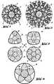
- Fig. 3a bis 3d geben, wiederum im Querschnitt, die Zusammenfassung von Strängen zu Kabeln wieder, wobei bei den einzelnen Kabeln in den den Kern umhüllenden Mänteln eine unterschiedliche Anzahl Stränge untergebracht ist;3a to 3d show, again in cross section, the combination of strands into cables, with a different number of strands being accommodated in the individual sheaths in the sheaths surrounding the core;
- Fig. 4 stellt im Querschnitt ein Band dar, zu dem mehrere Kabel vereinigt sind;Fig. 4 shows in cross section a band to which several cables are combined;
- Fig. 5 ist eine Aufsicht auf eine Ausführungsform eines Verankerungselementes für die Befestigung eines Bandes an einem Knochen, während5 is a top view of an embodiment of an anchoring element for attaching a ligament to a bone while
- Fig. 6 der Schnitt VI-VI von Fig. 5 ist.Figure 6 is section VI-VI of Figure 5.
Bei der Ausführungsform nach Fig. 1 besitzt ein in seiner Gesamtheit mit 1 bezeichneter Strang einen Kernfaden 2, der in diesem Fall in einem Metalldraht aus einer in der Implantattechnik üblichen Metall-Legierung, beispielsweise einer CoNiCrMoTi-Srhmiedelegierung, besteht. Um den Kernfaden 2 herum, sind in einem Kranz Mantelfäden 3 aus der gleichen Legierung konzentrisch und rotationssymmetrisch an-j geordnet. Diese Mantelfäden 3 sind - was aus der Zeichnung nicht ersichtlich ist - mit Vorteil' leicht seilartig verwunden, d. h. die Mantelfäden; 3 verlaufen in Längsrichtung schraubenförmig um den Kernfaden 2 herum.In the embodiment according to FIG. 1, a strand denoted in its entirety by 1 has a
Jeder einzelne Faden 2 bzw. 3 steckt bei der vorliegenden Ausführungsform in einem textilen Schlauch 4, durch den, wie bereits erwähnt, ein Abrieb an den die Belastungen aufnehmenden Drähten bzw. Fäden 2, 3 bei den zwischen den einzelnen »Fasern« des Bandes oder des Stranges auftretenden relativen Längsverschiebungen verhindert oder zumindest vermindert wird.Each
Die in ihren Schläuchen 4 verlaufenden Kern-und Mantelfäden 2 bzw. 3 sind als Ganzes von einer Stranghülle 5 umschlossen, durch die ihr mechanischer Zusammenhalt und die relative Lage der Mantelfäden 3 auf dem Umfang des Kranzes gewährleistet werden.The core and
Die Ausführungsform eines Stranges 7 nach Fig. 2 unterscheidet sich von derjenigen nach Fig. 1 lediglich dadurch, daß der Kernfaden 2 von zwei Kränzen aus Mantelfäden 3 bzw. 6 umgeben ist, wobei der Durchmesser der Mantelfäden 3 größer ist als derjenige der Mantelfäden 6 des äußeren Kranzes. Der Zusammenhalt des Stranges 7 ist auch hier durch eine Stranghülle 5 sichergestellt, wobei zur geometrischen Fixierung der Mantelfäden in den einzelnen Kränzen zusätzliche Hüllen 11 zwischen den Kränzen der Mantelfäden 3 bzw. 6 vorgesehen sein können; diese zusätzlichen textilen Hüllen erleichtern und vereinfachen vor allem das erwähnte Verseilen der Mantelfäden um den Kern herum.The embodiment of a strand 7 according to FIG. 2 differs from that according to FIG. 1 only in that the
Die Durchmesser des Kernfadens 2 können beispielsweise zwischen 0,1 und 1 mm betragen, während die Mantelfäden 3 bzw. 6 Durchmesser zwischen 0,05 und 0,5 mm haben. Die Abstimmungen zwischen dem Durchmesser des Kernfa- dens 2 und denjenigen der ihm im Einzelfall ; zugeordneten Mantelfäden 3 bzw. 6 erfolgt dabei so, daß die Durchmesser der Fäden vom Kern nach außen von Kranz zu Kranz (Fig. 2) abnehmen, um die Elastizität des Stranges des daraus gebildeten Bandes gemäß den eingangs er- 'wähnten Forderungen von innen nach außen zu steigern.The diameter of the
Die Schläuche 4 und die Stranghülle 5 sind beispielsweise ein Hohlgeflecht, wobei die der deutlichen Darstellung wegen mit großen Abständen gezeichneten einzelnen Flechtfäden auch so dicht wie möglich gepackt sein können; die Dichte des Geflechtes kann dabei im Kern wiederum größer sein als bei den Mantelfäden und bei der Stranghülle. Als bevorzugtes Material für die Schläuche 4 oder Stranghülle 5 dient Naturseide; fabrikatorisch einfacher ist es, die einzelnen Fäden 2 und 3 - ähnlich wie für Isolationen elektrischer Leitungen bekannt - mit Kunststoff zu ummanteln, was beispielsweise durch Tauchen des Fadens in ein Bad aus einem geeigneten Kunststoff erfolgen kann. Ebenso können die Stranghüllen aus derartigen Kunststoffmänteln bestehen.The hoses 4 and the
Obwohl bereits ein Strang 1 bzw. 7 als Bänder-oder Sehnenersatz direkt zu verwenden ist, ist es auch möglich, mehrere Stränge 1 bzw. 7 für den Aufbau eines Bandes mit höherer Belastungsfähigkeit zu benutzen. Wie in Fig. 3 gezeigt, bildet dabei beispielsweise ein Strang 7 den Kernstrang eines Kabels 8, den Stränge 1 als Mantelstränge konzentrisch und rotationssymmetrisch umgeben, wobei in dem Mantelkranz drei, vier oder mehr - je nach Durchmesser-Unterschied zwischen den Strängen 7 und 1, beispielsweise bis zu acht - Stränge angeordnet sein können. Die geforderte nach außen zunehmende Elastizität ist dabei beispielsweise durch die Verwendung eines steiferen Stranges 7 als Kemstrang und von elastischeren Strängen 1 als Mantelstränge gewährleistet, wobei die Elastizität der äußeren Bereiche durch eine verschieden große Anzahl der in einem Kranz vorgesehenen Stränge 1 in gewissem Umfang variiert werden kann. Je weniger Stränge 1 dabei in einem Kranz angeordnet werden, um so größer ist dabei außen die Elastizität. In Fig. 3 sinkt dabei die Elastizität außen stufenweise von Fig. 3a-3d.Although one
Jedes Kabel 8 ist dabei durch eine Kabelhülle 9 aus einem Naturseide-Geflecht zu einer Einheit zusammengefaßt.Each cable 8 is combined into a unit by a
Selbstverständlich können - wie bei den Strängen - auch Kabel aus einem Kernstrang und zwei oder mehreren Kränzen Mantelsträngen zusammengefügt werden.Of course - as with the strands - cables from a core strand and two or more rings of sheath strands can also be joined together.
Für Bänder, die extremen Belastungen ausgesetzt sind, lassen sich wiederum mehrere Kabel 8 zu einem Band vereinigen, wobei als Kernkabel beispielsweise ein Kabel 8d nach Fig. 3d verwendet wird, während die Mantelkabel aus Kabeln 8a nach Fig. 3a gebildet sind, wie dies Fig. 4 zeigt. Zusammengehalten wird auch dieses Band durch ein Naturseide-Geflecht als textile Umhüllung 10. 'For tapes that are exposed to extreme loads, a plurality of cables 8 can in turn be combined to form a tape, a
Als Beispiel einer Verankerung eines Bandendes am Knochen ist nach Fig. 5 und Fig. 6 eine Platte 17 vorgesehen, die mit einem Zapfen 15 durch die kortikale Schicht 16 in die Spongiosa 21 eingelassen und durch eine oder mehrere Schrauben 18 auf der kortikalen Schicht 16, befestigt ist. Auf diese Platte 17 ist ein Deckel 19 gesetzt und durch Schrauben 20 gehalten. Die Platte 17 und der Deckel 19 bilden zusammen zwei pollerartige Pfosten, wie sie zum Vertauen von Schiffen an Landungsstegen bekannt sind. Wie Fig. 5 zeigt, wird ein zu befestigendes Band 1 einfach um diese Pfosten geschlungen und durch Anziehen der den Deckel 19 auf die Platte 17 ziehenden Schrauben 20 festgeklemmt.5 and 6, a
Selbstverständlich ist die vorliegende Erfindung nicht auf die gezeigten Ausführungsbeispiele beschränkt, insbesondere nicht hinsichtlich der ausgewählten Materialien und hinsichtlich der skizzierten Verankerung des künstlichen Bandes am Knochen.Of course, the present invention is not limited to the exemplary embodiments shown, in particular not with regard to the selected materials and with regard to the sketched anchoring of the artificial ligament on the bone.
Claims (7)
Priority Applications (1)
| Application Number | Priority Date | Filing Date | Title |
|---|---|---|---|
| AT81102325TATE4773T1 (en) | 1980-06-03 | 1981-03-27 | TENDON AND/OR LIGAMENT REPLACEMENT. |
Applications Claiming Priority (2)
| Application Number | Priority Date | Filing Date | Title |
|---|---|---|---|
| CH4278/80 | 1980-06-03 | ||
| CH427880ACH644748A5 (en) | 1980-06-03 | 1980-06-03 | STRING AND / OR TAPE REPLACEMENT MATERIAL. |
Publications (3)
| Publication Number | Publication Date |
|---|---|
| EP0041111A2 EP0041111A2 (en) | 1981-12-09 |
| EP0041111A3 EP0041111A3 (en) | 1981-12-16 |
| EP0041111B1true EP0041111B1 (en) | 1983-09-28 |
Family
ID=4273124
Family Applications (1)
| Application Number | Title | Priority Date | Filing Date |
|---|---|---|---|
| EP81102325AExpiredEP0041111B1 (en) | 1980-06-03 | 1981-03-27 | Artificial tendon and/or ligament |
Country Status (6)
| Country | Link |
|---|---|
| US (1) | US4345339A (en) |
| EP (1) | EP0041111B1 (en) |
| AT (1) | ATE4773T1 (en) |
| CH (1) | CH644748A5 (en) |
| DE (1) | DE3161005D1 (en) |
| ES (1) | ES8400236A1 (en) |
Families Citing this family (55)
| Publication number | Priority date | Publication date | Assignee | Title |
|---|---|---|---|---|
| CH651463A5 (en)* | 1981-06-24 | 1985-09-30 | Sulzer Ag | STRING AND / OR TAPE REPLACEMENT. |
| US4483023A (en)* | 1981-08-21 | 1984-11-20 | Meadox Medicals, Inc. | High-strength ligament prosthesis |
| US5049155A (en)* | 1982-09-10 | 1991-09-17 | W. L. Gore & Associates, Inc. | Prosthesis for tensile-load-carrying tissue and method of manufacture |
| US4610688A (en)* | 1983-04-04 | 1986-09-09 | Pfizer Hospital Products Group, Inc. | Triaxially-braided fabric prosthesis |
| EP0148369B1 (en)* | 1983-12-08 | 1987-06-10 | Walter Koss | Penis prothesis |
| EP0145492A3 (en)* | 1983-12-15 | 1987-01-21 | A.W.Showell (Surgicraft) Limited | Replacements for ligaments and tendons |
| FI78238C (en)* | 1985-07-09 | 1989-07-10 | Biocon Oy | SURGICAL PURPOSE SYNTHESIS. |
| US4792336A (en)* | 1986-03-03 | 1988-12-20 | American Cyanamid Company | Flat braided ligament or tendon implant device having texturized yarns |
| FR2596641B1 (en)* | 1986-04-04 | 1988-06-24 | Ordi Sa | ARTIFICIAL LIGAMENT |
| GB8611853D0 (en)* | 1986-05-15 | 1986-06-25 | Beacon J P | Artificial ligament |
| DE3711465A1 (en)* | 1987-04-04 | 1988-10-13 | Kernforschungsz Karlsruhe | DEVICE FOR IN VIVO FASTENING OF A CROSSBAND REPLACEMENT ON THE BONE |
| GB2203342B (en)* | 1987-04-07 | 1991-12-11 | Julian Garth Ellis | Radio-opaque tracer for surgical implants |
| JPH03505823A (en)* | 1987-08-19 | 1991-12-19 | イー・アイ・デユポン・デ・ニモアス・アンド・カンパニー | flexible tissue prosthesis |
| EP0312494A3 (en)* | 1987-10-16 | 1991-01-16 | Institut Straumann Ag | Alloplastic material for building of a part of an artificial soft tissue or reinforcement of a part of a natural soft tissue |
| US5197983A (en)* | 1988-04-19 | 1993-03-30 | W. L. Gore & Associates, Inc. | Ligament and tendon prosthesis |
| US4883486A (en)* | 1988-05-31 | 1989-11-28 | Indu Kapadia | Prosthetic ligament |
| US5026398A (en)* | 1988-07-01 | 1991-06-25 | The Minnesota Mining And Manufacturing Company | Abrasion resistant prosthetic device |
| US5108433A (en)* | 1989-08-18 | 1992-04-28 | Minnesota Mining And Manufacturing Company | Tensioning means for prosthetic devices |
| US5002574A (en)* | 1989-08-18 | 1991-03-26 | Minnesota Mining And Manufacturing Co. | Tensioning means for prosthetic devices |
| FR2653718A1 (en)* | 1989-10-26 | 1991-05-03 | Sita | METHOD OF DIFFERENTIATED TRANSPORT AND VEHICLES FOR THEIR PRODUCTION. |
| EP0447355A1 (en)* | 1990-03-12 | 1991-09-18 | Gebrüder Sulzer Aktiengesellschaft | Implant for the human body |
| DE4012602C2 (en)* | 1990-04-20 | 1994-06-09 | Ethicon Gmbh | Implant cord |
| GB9011435D0 (en)* | 1990-05-22 | 1990-07-11 | Goodfellow John W | Artificial ligaments |
| US5540703A (en)* | 1993-01-06 | 1996-07-30 | Smith & Nephew Richards Inc. | Knotted cable attachment apparatus formed of braided polymeric fibers |
| US5456722A (en)* | 1993-01-06 | 1995-10-10 | Smith & Nephew Richards Inc. | Load bearing polymeric cable |
| DE19833796B4 (en)* | 1998-07-21 | 2015-10-01 | Johnson & Johnson Medical Gmbh | Braided resorbable implant |
| US6770076B2 (en) | 2001-02-12 | 2004-08-03 | Opus Medical, Inc. | Method and apparatus for attaching connective tissues to bone using a knotless suture anchoring device |
| US7597715B2 (en) | 2005-04-21 | 2009-10-06 | Biomet Manufacturing Corp. | Method and apparatus for use of porous implants |
| US8123814B2 (en) | 2001-02-23 | 2012-02-28 | Biomet Manufacturing Corp. | Method and appartus for acetabular reconstruction |
| WO2004082724A2 (en)* | 2003-03-18 | 2004-09-30 | Opus Medical Inc. | Optimized suture braid |
| US20050192581A1 (en)* | 2004-02-27 | 2005-09-01 | Molz Fred J. | Radiopaque, coaxial orthopedic tether design and method |
| US8021432B2 (en) | 2005-12-05 | 2011-09-20 | Biomet Manufacturing Corp. | Apparatus for use of porous implants |
| US8292967B2 (en) | 2005-04-21 | 2012-10-23 | Biomet Manufacturing Corp. | Method and apparatus for use of porous implants |
| US8066778B2 (en) | 2005-04-21 | 2011-11-29 | Biomet Manufacturing Corp. | Porous metal cup with cobalt bearing surface |
| US8266780B2 (en) | 2005-04-21 | 2012-09-18 | Biomet Manufacturing Corp. | Method and apparatus for use of porous implants |
| US7635447B2 (en) | 2006-02-17 | 2009-12-22 | Biomet Manufacturing Corp. | Method and apparatus for forming porous metal implants |
| EP2010104B1 (en)* | 2006-04-25 | 2018-09-05 | Teleflex Medical Incorporated | Calcium phosphate polymer composite and method |
| US8052593B2 (en)* | 2006-10-24 | 2011-11-08 | Ams Research Corporation | Implantable malleable penile prosthetic device |
| CA2682701A1 (en)* | 2007-03-20 | 2008-09-25 | Serica Technologies, Inc. | Prosthetic device and method of manufacturing the same |
| US7905918B2 (en)* | 2007-08-23 | 2011-03-15 | William Wayne Cimino | Elastic metallic replacement ligament |
| US8911350B2 (en) | 2007-10-23 | 2014-12-16 | Ams Research Corporation | Malleable prosthesis with enhanced concealability |
| US8114011B2 (en)* | 2007-10-23 | 2012-02-14 | Ams Research Corporation | Corrugated inflatable penile prosthesis cylinder |
| US8123674B2 (en)* | 2007-11-12 | 2012-02-28 | Ams Research Corporation | Corrugated expansion-constraining sleeve for an inflatable penile prosthesis cylinder |
| US10070955B2 (en)* | 2007-11-15 | 2018-09-11 | Boston Scientific Scimed, Inc. | Prosthesis with bendable central region |
| US8052594B2 (en)* | 2007-11-20 | 2011-11-08 | Ams Research Corporation | Prosthetic device with protrusions for girth |
| US7988568B2 (en)* | 2008-01-17 | 2011-08-02 | Nike, Inc. | Golf clubs and golf club heads with adjustable center of gravity and moment of inertia characteristics |
| EP2349089A4 (en)* | 2008-11-21 | 2014-01-15 | Lifecell Corp | Reinforced biologic material |
| US20110190886A1 (en)* | 2010-01-29 | 2011-08-04 | Wisconsin Alumni Research Foundation | Braided tertiary nanofibrous structure for ligament, tendon, and muscle tissue implant |
| US8808326B2 (en) | 2010-11-24 | 2014-08-19 | Arthrocare Corporation | Suture |
| US9801702B2 (en) | 2010-12-16 | 2017-10-31 | Boston Scientific Scimed, Inc. | Artificial sphincter system and method |
| KR101088834B1 (en)* | 2011-04-12 | 2011-12-06 | 디에스알 주식회사 | Synthetic fiber rope for crane and manufacturing method thereof |
| EP3104809B1 (en)* | 2014-02-13 | 2017-12-27 | Antonio Sambusseti | Non-absorbable tissue reconstruction device, in particular for tissues such as ligaments |
| US10952855B2 (en) | 2016-03-24 | 2021-03-23 | Boston Scientific Scimed, Inc. | Inflatable penile prosthesis with reversible flow pump assembly |
| EP3704298A1 (en) | 2017-11-01 | 2020-09-09 | Hampidjan HF. | Bend fatigue resistant blended rope |
| CN113521389B (en)* | 2019-10-21 | 2023-05-12 | 深圳市立心科学有限公司 | Composite artificial fiber element |
Family Cites Families (10)
| Publication number | Priority date | Publication date | Assignee | Title |
|---|---|---|---|---|
| US3176316A (en)* | 1963-01-07 | 1965-04-06 | Bruce R Bodell | Plastic prosthetic tendon |
| US3513484A (en)* | 1967-10-27 | 1970-05-26 | Extracorporeal Med Spec | Artificial tendon |
| FR2135825A5 (en)* | 1971-04-30 | 1972-12-22 | Rhone Poulenc Sa | |
| US3805300A (en)* | 1972-07-28 | 1974-04-23 | Cutter Lab | Tendon prosthesis |
| FR2213761B1 (en)* | 1973-01-17 | 1976-05-14 | Rambert Andre | |
| GB1465744A (en)* | 1974-01-30 | 1977-03-02 | Ethicon Inc | Attaching fibrous connective tissue to bone |
| CS169274B1 (en)* | 1974-03-29 | 1976-07-29 | ||
| US4149277A (en)* | 1977-06-22 | 1979-04-17 | General Atomic Company | Artificial tendon prostheses |
| US4187558A (en)* | 1977-10-25 | 1980-02-12 | Cutter Laboratories, Inc. | Prosthetic ligament |
| US4246660A (en)* | 1978-12-26 | 1981-01-27 | Queen's University At Kingston | Artificial ligament |
- 1980
- 1980-06-03CHCH427880Apatent/CH644748A5/ennot_activeIP Right Cessation
- 1981
- 1981-03-27ATAT81102325Tpatent/ATE4773T1/enactive
- 1981-03-27EPEP81102325Apatent/EP0041111B1/ennot_activeExpired
- 1981-03-27DEDE8181102325Tpatent/DE3161005D1/ennot_activeExpired
- 1981-04-13ESES501305Apatent/ES8400236A1/ennot_activeExpired
- 1981-05-19USUS06/265,067patent/US4345339A/ennot_activeExpired - Lifetime
Also Published As
| Publication number | Publication date |
|---|---|
| DE3161005D1 (en) | 1983-11-03 |
| EP0041111A3 (en) | 1981-12-16 |
| EP0041111A2 (en) | 1981-12-09 |
| ATE4773T1 (en) | 1983-10-15 |
| ES501305A0 (en) | 1983-11-01 |
| CH644748A5 (en) | 1984-08-31 |
| ES8400236A1 (en) | 1983-11-01 |
| US4345339A (en) | 1982-08-24 |
Similar Documents
| Publication | Publication Date | Title |
|---|---|---|
| EP0041111B1 (en) | Artificial tendon and/or ligament | |
| EP0054784B1 (en) | Overhead cable with tension members | |
| DE69223264T2 (en) | IMPLANTABLE LINE | |
| EP0162178B1 (en) | Lead for implantation into the human or animal body, comprising a helix cable with at least one conductor | |
| DE68910157T2 (en) | Braided textile coverings. | |
| EP0201667B1 (en) | Artificial tendon made of a tubular textile structure | |
| DE4233230B4 (en) | endoscope | |
| DE69331069T2 (en) | IMPLANTABLE WIRE IN COMPOSITE DESIGN | |
| DE69513181T2 (en) | PRESTIGIBLE PENIS ENDOPROTHESIS | |
| DE803801C (en) | Metallic cable, especially for the production of inserts for pneumatic tires | |
| EP0499089B1 (en) | Flexible protection hose for oblong objects | |
| DE2732376A1 (en) | LIGHT GUIDE CABLES | |
| CH656970A5 (en) | HIGHLY FLEXIBLE INSULATED ELECTRIC CABLE, METHOD FOR THE PRODUCTION AND USE OF THE CABLE. | |
| CH668900A5 (en) | ARTIFICIAL CROSSBAND FOR A KNEE JOINT. | |
| EP0067929B1 (en) | Tendon and/or ligament prosthesis | |
| DE7438507U (en) | Electrical cable with strain relief | |
| EP0092797B1 (en) | Multi-pole electrical lead | |
| DE69213110T2 (en) | Manufacturing process for an optical cable from hollow wires and the resulting cable | |
| DE3336617A1 (en) | Multi-core flexible electrical cable | |
| DE2720071C2 (en) | Tensile, flexible electrical cable | |
| DE2948031C2 (en) | Temperature-stable switching line for electrical heating devices | |
| DE4232012C2 (en) | Steel cable | |
| DE9113602U1 (en) | Wire strand for a piece of jewelry | |
| DE736033C (en) | Airspace-insulated electrical cables, in particular for the transmission of messages | |
| DE2052392C3 (en) | Electric floating cable |
Legal Events
| Date | Code | Title | Description |
|---|---|---|---|
| PUAI | Public reference made under article 153(3) epc to a published international application that has entered the european phase | Free format text:ORIGINAL CODE: 0009012 | |
| PUAL | Search report despatched | Free format text:ORIGINAL CODE: 0009013 | |
| 17P | Request for examination filed | Effective date:19810327 | |
| AK | Designated contracting states | Designated state(s):AT DE FR GB IT NL | |
| AK | Designated contracting states | Designated state(s):AT DE FR GB IT NL | |
| ITF | It: translation for a ep patent filed | ||
| GRAA | (expected) grant | Free format text:ORIGINAL CODE: 0009210 | |
| AK | Designated contracting states | Designated state(s):AT DE FR GB IT NL | |
| REF | Corresponds to: | Ref document number:4773 Country of ref document:AT Date of ref document:19831015 Kind code of ref document:T | |
| REF | Corresponds to: | Ref document number:3161005 Country of ref document:DE Date of ref document:19831103 | |
| ET | Fr: translation filed | ||
| PLBE | No opposition filed within time limit | Free format text:ORIGINAL CODE: 0009261 | |
| STAA | Information on the status of an ep patent application or granted ep patent | Free format text:STATUS: NO OPPOSITION FILED WITHIN TIME LIMIT | |
| 26N | No opposition filed | ||
| ITTA | It: last paid annual fee | ||
| PGFP | Annual fee paid to national office [announced via postgrant information from national office to epo] | Ref country code:GB Payment date:20000211 Year of fee payment:20 | |
| PGFP | Annual fee paid to national office [announced via postgrant information from national office to epo] | Ref country code:NL Payment date:20000223 Year of fee payment:20 | |
| PGFP | Annual fee paid to national office [announced via postgrant information from national office to epo] | Ref country code:DE Payment date:20000224 Year of fee payment:20 Ref country code:AT Payment date:20000224 Year of fee payment:20 | |
| PGFP | Annual fee paid to national office [announced via postgrant information from national office to epo] | Ref country code:FR Payment date:20000331 Year of fee payment:20 | |
| PG25 | Lapsed in a contracting state [announced via postgrant information from national office to epo] | Ref country code:GB Free format text:LAPSE BECAUSE OF EXPIRATION OF PROTECTION Effective date:20010326 | |
| PG25 | Lapsed in a contracting state [announced via postgrant information from national office to epo] | Ref country code:NL Free format text:LAPSE BECAUSE OF EXPIRATION OF PROTECTION Effective date:20010327 Ref country code:AT Free format text:LAPSE BECAUSE OF EXPIRATION OF PROTECTION Effective date:20010327 | |
| REG | Reference to a national code | Ref country code:GB Ref legal event code:PE20 Effective date:20010326 | |
| NLV7 | Nl: ceased due to reaching the maximum lifetime of a patent | Effective date:20010327 |