EP0036926B1 - A device for the diffusion of substances between two fluids via semipermeable membranes - Google Patents
A device for the diffusion of substances between two fluids via semipermeable membranesDownload PDFInfo
- Publication number
- EP0036926B1 EP0036926B1EP81100686AEP81100686AEP0036926B1EP 0036926 B1EP0036926 B1EP 0036926B1EP 81100686 AEP81100686 AEP 81100686AEP 81100686 AEP81100686 AEP 81100686AEP 0036926 B1EP0036926 B1EP 0036926B1
- Authority
- EP
- European Patent Office
- Prior art keywords
- plates
- ducts
- transverse
- edges
- accordance
- Prior art date
- Legal status (The legal status is an assumption and is not a legal conclusion. Google has not performed a legal analysis and makes no representation as to the accuracy of the status listed.)
- Expired
Links
- 239000012528membraneSubstances0.000titleclaimsdescription31
- 239000012530fluidSubstances0.000titleclaimsdescription14
- 239000000126substanceSubstances0.000titleclaimsdescription4
- 238000009792diffusion processMethods0.000titleclaimsdescription3
- 125000006850spacer groupChemical group0.000claimsdescription35
- 239000000463materialSubstances0.000claimsdescription23
- 238000007789sealingMethods0.000claimsdescription21
- 239000008280bloodSubstances0.000claimsdescription18
- 210000004369bloodAnatomy0.000claimsdescription18
- 239000011324beadSubstances0.000claimsdescription14
- 230000003467diminishing effectEffects0.000claims1
- 239000003566sealing materialSubstances0.000description13
- 239000007788liquidSubstances0.000description11
- 238000000502dialysisMethods0.000description8
- 238000002347injectionMethods0.000description4
- 239000007924injectionSubstances0.000description4
- 239000011230binding agentSubstances0.000description1
- 238000005266castingMethods0.000description1
- 238000010276constructionMethods0.000description1
- 230000003292diminished effectEffects0.000description1
- 210000003734kidneyAnatomy0.000description1
- 238000006213oxygenation reactionMethods0.000description1
- 229920002635polyurethanePolymers0.000description1
- 239000004814polyurethaneSubstances0.000description1
- 238000000746purificationMethods0.000description1
Images


Classifications
- B—PERFORMING OPERATIONS; TRANSPORTING
- B01—PHYSICAL OR CHEMICAL PROCESSES OR APPARATUS IN GENERAL
- B01D—SEPARATION
- B01D53/00—Separation of gases or vapours; Recovering vapours of volatile solvents from gases; Chemical or biological purification of waste gases, e.g. engine exhaust gases, smoke, fumes, flue gases, aerosols
- B01D53/22—Separation of gases or vapours; Recovering vapours of volatile solvents from gases; Chemical or biological purification of waste gases, e.g. engine exhaust gases, smoke, fumes, flue gases, aerosols by diffusion
- B—PERFORMING OPERATIONS; TRANSPORTING
- B01—PHYSICAL OR CHEMICAL PROCESSES OR APPARATUS IN GENERAL
- B01D—SEPARATION
- B01D63/00—Apparatus in general for separation processes using semi-permeable membranes
- B01D63/14—Pleat-type membrane modules
- B—PERFORMING OPERATIONS; TRANSPORTING
- B01—PHYSICAL OR CHEMICAL PROCESSES OR APPARATUS IN GENERAL
- B01D—SEPARATION
- B01D2313/00—Details relating to membrane modules or apparatus
- B01D2313/14—Specific spacers
Definitions
- the present inventionrelates to a device for diffusion of substances between two fluids via one or more semipermeable membranes which are arranged in a stack separated by elongated spacer plates which on their surfaces are provided with ducts connected to inlets and outlets for said fluids, the spacer plates being arranged in the folds of one or more membranes folded in zigzag, including two transverse ducts arranged near to opposite end edges of the plates and substantially parallel with these end edges which open onto one of the two lateral edges which connect the end edges of the plates, each of said transverse ducts extending on one and the same side of the spacer plate in such a way that the space outside the mouth of the duct is directly connected with the working ducts connected to the transverse duct.
- the device in accordance with the inventionis intended in the first place to be used for the purification of blood, that is to say as a so-called artificial kidney.
- the apparatus in accordance with the inventioncan also be used for many other purposes. It may be used for example for the oxygenation of blood.
- the device in accordance with the inventionmay be used for the transfer of substances from one gas to another.
- the term fluid, as used in the following description,means therefore gas as well as liquid.
- the device according to the present inventionis characterized in that the transverse ducts extend transversely over the entire spacer plates and are open outwardly at both the opposite lateral edges.
- This constructionmakes it also possible, for example, for two transverse ducts arranged straight opposite one another to be utilized for the supply of one medium, whilst a space between them and separated from them by two membrane layers can be utilized for the supply of the other fluid.
- Preferably support membersare located in said transverse ducts close to one of its ends.
- Said support membersmay for instance include a plurality of rib members.
- the bottom of the opposite end of said transverse ductsare instead preferably flat and free of said support members.
- the membrane materialis preferably arranged folded with its folding edges parallel and substantially coinciding with the lateral edges of the plates. The lateral edges may then assist in the folding.
- the platesare preferably arranged so that they are inserted into the membrane material from one side only, that is to say into every other fold.
- One of the said fluidscan then be supplied from this side, whilst the other fluid can be introduced from the opposite side, that is to say into the folds which do not contain any spacer plates.
- another type of spacer platesmay be inserted into the last- named folds.
- sealing beadsare arranged in longitudinal direction of the plates parallel with their lateral edges and near these edges, whose object it is to press the membrane material pieced between them against the adjoining spacer plate.
- sealing beadsmay be arranged in transverse direction of the plates between the said transverse ducts and adjoining front edges, parallel with these edges, in order to press the membrane material placed between them tightly against the adjoining spacer plate. Thanks to these sealing beads, the. required quantity of sealing material, which otherwise is injected and used to separate the two fluids from one another, can be limited.
- a particularly good tightnessis obtained if the stack of spacer plates and membrane material between them is arranged in an outer casing with inlets and outlets for the respective fluids.
- the sealing materialcan then be cast in between the outer casing and the stack in the form of strands.
- Two strands of sealing materialcan be adapted so as to extend around the pack in its transverse direction, as reckoned from the front edges just inside the openings of the respective transverse ducts.
- two other strandsmay be adapted, so as to extend around the pack in its longitudinal direction just inside the lateral edges in longitudinal direction of the spacer plates.
- a relatively small amount of sealing materialis required, as compared with when it has to be spread out between the casing and the stack of spacer plates. Injection of sealing material is facilitated, if the said four strands are cast together to a unit.
- the inlets and outlets of the casing for the respective fluidsare arranged appropriately outside all the said strands of sealing material in connection with the openings of the transverse ducts and in connection with the space between the doubled membrane material arranged in the transverse ducts.
- the casingconsists of a boxlike main part and a lid.
- a particularly good tightnesscan be achieved if a further strand of sealing material is cast in between the lid and the boxliké main part.
- sealing beadsmay be provided in the main part of the casing and/or the lid, in order to seal off the sealing material against the fluids fed into the apparatus. This is particularly important, if the device is to be heat sterilized whilst filled with liquid.
- ribsare provided between the transverse ducts and the working surfaces proper of the spacer plates which are adapted so as to support from the outside the doubled membrane material between them, without fully compressing the same.
- the distance between two such opposite ribs on adjoining platesmay be increased in the transverse direction of the plate in the direction from the blood inlet and diminished in the direction towards the blood outlet. In this way the device is utilized in the best possible manner over the whole of its width.
- the device in accordance with the invention shown as an exampleis intended first and foremost to be used for dialysis and will be described therefore in the following with reference to such a treatment.
- the devicecomprises an outer casing, which as a whole is designated by numeral 10.
- This casingconsists of a boxlike bottom part 9a and an upper lid 9b.
- An inlet and an outlet for bloodare designated 6 and 7 respectively and numerals 4 and 5 designate an inlet and an outlet respectively for dialysate, if the device is to be used as a dialyser.
- Numerals 3a and 3bdesignate recessed portions, the first of which is intended to be used for the securing of the device in a dialysis machine, whilst the other is provided in order to economize material.
- the casing 10 shown in Figure 1is intended to contain a stack of spacer plates and membrane material between them.
- Figure 3is shown a preferred arrangement of such a stack with the spacer plates designated 1 and the membrane material 2.
- the membrane material 2is folded, so that it forms double folds 2a where the blood can enter as indicated by the arrows B.
- the dialysateon the other hand can enter from the opposite side, as indicated by the arrows D. In this way the blood can flow on one side of the membrane, that is to say inside the double folds 2a, whilst the dialysate flows in ducts in the plates on the opposite side of the membrane material.
- FIG 4shows an alternative arrangement of the membrane material and spacer plates.
- the membrane materialis designated here 2', whilst the spacer plates are designated 1 a and 1 b respectively.
- the spacer plates 1 acomprise ducts for the dialysis liquid D, whilst the spacer plates 1 b comprise ducts for the blood B.
- Figure 2shows from above the lid 9b belonging to the casing 10 shown in Figure 1.
- the Figureis intended primarily to illustrate the position of the sections shown in the Figures 5-9.
- Numerals 11 and 12designate the inlet for the injection of a sealing material, for example polyurethane. The manner in which the sealing is carried out will be described in more detail in the following.
- Numeral 13designates orientation holes intended to facilitate the stacking of the apparatus as a whole.
- Figure 5shows a section along line V-V in Figure 2.
- Numerals 14 and 15designate strands of sealing material, which will be described more fully in the following, with reference primarily to Figures 10 and 12. In connection therewith, a more detailed explanation will also be given of the sealing beads 16.
- Numeral 4adesignates an extension of the inlet 4 for dialysis liquid and 7a designates a corresponding extension of the blood outlet 7.
- Figure 8which constitutes a section along line VIII-VIII in Figure 2, examples of sealing strands 14. and 15 and sealing beads 16 are shown.
- Figure 8also shows a cross-section through the transverse ducts 18 arranged across the spacer plates 2 near their front edges 17 and parallel with these.
- Figure 8shows further sealing grooves 19, which will be explained in more detail in the following.
- FIGs 10 and 11are shown the lid 9b, seen from underneath and in the form of a longitudinal section.
- the sealing strands 14 shown .in Figures 5-8are formed through ducts 14a, which are in connection with the injection openings 11, shown in Figure 2.
- the ducts 14acontinue also in the bottom part 9a. Consequently, the strands 14 will extend around the whole stack of spacer plates 1 and the membrane material 2 between them in longitudinal direction as well as in transverse direction of the stack.
- the holes 13which facilitate stacking and the injection holes for the sealing strands 15.
- sealing beads 16are evident on both sides of the ducts 14a.
- numeral 22designates a clamping flange intended for the securing of the lid.
- Figure 12On both sides of the grooves 14a, Figure 12 also shows the sealing beads 16 indicated in the Figures 5-8. These are intended to prevent the sealing material used from being forced out of the grooves 14a. At the same time, these sealing beads 16 prevent the blood as well as the dialysis liquid or other liquids supplied from making contact with the sealing material used. This is particularly important, if the dialyser is intended to be heat-sterilized when filled with liquid, since otherwise material might be transferred from the binder into the incoming liquids.
- the lid 9bis secured to the bottom part 9a with the help of the clamping flange 22, which engages underneath a corresponding clamping flange 23 on the bottom part.
- Numerals 4a, 5a, 6a and 7a in Figure 12designate extensions of the corresponding inlets and outlets 4, 5, 6 and 7 for dialysis liquid and blood respectively.
- Figures 14-20show a preferred embodiment of the spacer plates 1 included in the device in accordance with the invention.
- Figure 14shows a plate seen from underneath, whilst Figure 15 shows the same seen from above and Figure 16 is an end view.
- the platecan be patterned in a largely conventional manner, for example in accordance with any one of the above-mentioned Swedish patents. However, it is essential in accordance with the invention that the plate is provided at its ends with the transverse ducts 18, which are also shown in Figure 8. These transverse ducts 18 should open onto at least one of the lateral edges 24. In the example shown, the transverse ducts 18 run transversely over the plates 1 and thus open onto both lateral edges 24. The transverse ducts are parallel with the front edges of the plates. As can be seen from Figures 17 and 18, the transverse ducts 18 contain ribs 25, which are adapted so as to press adjoining membranes in a tight manner against adjoining spacer plates.
- the transverse ductscomprise smaller supporting ribs or supporting fins 26, which are intended simply to support the membranes from the outside.
- Similar pressure ribs 27are present with somewhat lower supporting ribs 28 marked in black.
- the supporting ribs 28become progressively lower, the farther away they are situated from the blood inlet and the blood outlet respectively, which is indicated by the arrows B in Figure 15.
- the working surface itselfas can be seen more clearly in Figure 19, consists of zigzag-shaped ridges 29 and 30.
- Figure 20shows that the ridges 30 are somewhat lower compared with the ridges 29.
- Numeral 31designates transverse distributing ducts, which are intended to facilitate the distribution of the blood and of the dialysis liquid on passing the supporting points 32 and the casting points 33.
- Numeral 19designates sealing beads arranged between the transverse ducts 18 and the front edges 17. Corresponding sealing beads placed parallel with the longitudinal edges 24 of the plate are designated 34. They can be seen, for example, also in Figure 9. Thanks to the sealing beads 19 and 34, the quantity of sealing material injected can be limited to the strands 14 (Fig. 5-8).
- support members 18aare located in the transverse ducts 18 close to one of its ends in the form of a plurality of rib members.
- the bottom 18b of the opposite end of the transverse ducts 18is instead flat and free of said support members.
Landscapes
- Chemical & Material Sciences (AREA)
- Chemical Kinetics & Catalysis (AREA)
- Engineering & Computer Science (AREA)
- Analytical Chemistry (AREA)
- General Chemical & Material Sciences (AREA)
- Oil, Petroleum & Natural Gas (AREA)
- External Artificial Organs (AREA)
- Separation Using Semi-Permeable Membranes (AREA)
Description
- The present invention relates to a device for diffusion of substances between two fluids via one or more semipermeable membranes which are arranged in a stack separated by elongated spacer plates which on their surfaces are provided with ducts connected to inlets and outlets for said fluids, the spacer plates being arranged in the folds of one or more membranes folded in zigzag, including two transverse ducts arranged near to opposite end edges of the plates and substantially parallel with these end edges which open onto one of the two lateral edges which connect the end edges of the plates, each of said transverse ducts extending on one and the same side of the spacer plate in such a way that the space outside the mouth of the duct is directly connected with the working ducts connected to the transverse duct.
- The device in accordance with the invention is intended in the first place to be used for the purification of blood, that is to say as a so-called artificial kidney. However, it will be clear to those skilled in the art, that the apparatus in accordance with the invention can also be used for many other purposes. It may be used for example for the oxygenation of blood. Alternatively, the device in accordance with the invention may be used for the transfer of substances from one gas to another. The term fluid, as used in the following description, means therefore gas as well as liquid.
- Apparatuses of the above-mentioned type are known in themselves and are described in detail for example in the German "Offen- legungsschrift" 25 23 803 and US patent specifications 3 585 131, 3 738 495 and 3 396 849. It may be said, therefore, that these documents constitute part of the background art. For further illustration of the same, reference is made to Swedish patents 218 441, 301 029, 325 370, 314 167, 342 144, 355 293, 395 119, 393 534 and 407 900, all of which show apparatuses comprising a stack of spacer plates with membranes preferably arranged in pairs between them which, however, cannot be said to be folded in zigzag. Such folding is however disclosed instead, for example, in the above first mentioned US patent specifications and in the US patent specifications 4116841, 3979295, 3862031, 3 788 482 and 3 780 870.
- The device according to the present invention is characterized in that the transverse ducts extend transversely over the entire spacer plates and are open outwardly at both the opposite lateral edges. As a result, a very simple apparatus is obtained, wherein both the said fluids can be sealed off securely in respect of one another.
- This construction makes it also possible, for example, for two transverse ducts arranged straight opposite one another to be utilized for the supply of one medium, whilst a space between them and separated from them by two membrane layers can be utilized for the supply of the other fluid.
- Preferably support members are located in said transverse ducts close to one of its ends. Said support members may for instance include a plurality of rib members. The bottom of the opposite end of said transverse ducts are instead preferably flat and free of said support members.
- The membrane material is preferably arranged folded with its folding edges parallel and substantially coinciding with the lateral edges of the plates. The lateral edges may then assist in the folding.
- The plates are preferably arranged so that they are inserted into the membrane material from one side only, that is to say into every other fold. One of the said fluids can then be supplied from this side, whilst the other fluid can be introduced from the opposite side, that is to say into the folds which do not contain any spacer plates. Alternatively, another type of spacer plates may be inserted into the last- named folds.
- A particularly good seal can be achieved if sealing beads are arranged in longitudinal direction of the plates parallel with their lateral edges and near these edges, whose object it is to press the membrane material pieced between them against the adjoining spacer plate. In the same way sealing beads may be arranged in transverse direction of the plates between the said transverse ducts and adjoining front edges, parallel with these edges, in order to press the membrane material placed between them tightly against the adjoining spacer plate. Thanks to these sealing beads, the. required quantity of sealing material, which otherwise is injected and used to separate the two fluids from one another, can be limited.
- A particularly good tightness is obtained if the stack of spacer plates and membrane material between them is arranged in an outer casing with inlets and outlets for the respective fluids. The sealing material can then be cast in between the outer casing and the stack in the form of strands. Two strands of sealing material can be adapted so as to extend around the pack in its transverse direction, as reckoned from the front edges just inside the openings of the respective transverse ducts. At the same time two other strands may be adapted, so as to extend around the pack in its longitudinal direction just inside the lateral edges in longitudinal direction of the spacer plates. For such an arrangement, a relatively small amount of sealing material is required, as compared with when it has to be spread out between the casing and the stack of spacer plates. Injection of sealing material is facilitated, if the said four strands are cast together to a unit.
- The inlets and outlets of the casing for the respective fluids are arranged appropriately outside all the said strands of sealing material in connection with the openings of the transverse ducts and in connection with the space between the doubled membrane material arranged in the transverse ducts.
- In a preferred embodiment of the invention, the casing consists of a boxlike main part and a lid. A particularly good tightness can be achieved if a further strand of sealing material is cast in between the lid and the boxliké main part.
- On either side of the said sealing strands, sealing beads may be provided in the main part of the casing and/or the lid, in order to seal off the sealing material against the fluids fed into the apparatus. This is particularly important, if the device is to be heat sterilized whilst filled with liquid.
- In a preferred embodiment, ribs are provided between the transverse ducts and the working surfaces proper of the spacer plates which are adapted so as to support from the outside the doubled membrane material between them, without fully compressing the same. The distance between two such opposite ribs on adjoining plates may be increased in the transverse direction of the plate in the direction from the blood inlet and diminished in the direction towards the blood outlet. In this way the device is utilized in the best possible manner over the whole of its width.
- In the following the invention will be described in greater detail with reference to the enclosed drawings, which show by way of example a preferred embodiment of the subject of the invention and also an alternative embodiment.
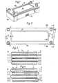
- Figure 1 represents a perspective view of a complete device in accordance with the invention in a preferred embodiment.
- Figure 2 shows the same device seen from above.
- Figure 3 shows schematically a first arrangement of a stack of spacer plates and membrane material between them arranged in a device in accordance with the invention.
- Figure 4 shows an alternative arrangement for such a stack.
- Figure 5 shows a section along line V-V in Figure 2.
- Figure 6 and 7 show on an enlarged scale the left-hand and the right-hand parts respectively of Figure 5.
- Figure 8 shows on the same enlarged scale a section along the line VIII-VIII in Figure 2.
- Figure 9 shows a smaller part of the section along line IX-IX in Figure 2.
- Figures 10 and 11 represent a view from underneath and a longitudinal section of a lid belonging to the outer casing of the device in accordance with the invention.
- Figures 12 and 13 show in the same manner the remainder of the casing, that is to say the bottom part seen from above and from the side partly in section.
- Figures 14 and 15 show a spacer plate included in the device seen from above and from underneath.
- Figure 16 shows an end view of the same spacer plate.
- Figure 17 shows a section along line XVII-XVII in Figure 15.
- Figure 18 shows a section along line XVIII-XVIII in Figure 14:
- Figure 19 shows the circular area XIX from Figure 15 detached and enlarged.
- Figure 20 finally shows a section along line XX-XX in Figure 19.
- The device in accordance with the invention shown as an example is intended first and foremost to be used for dialysis and will be described therefore in the following with reference to such a treatment.
- The device comprises an outer casing, which as a whole is designated by
numeral 10. This casing consists of aboxlike bottom part 9a and anupper lid 9b. An inlet and an outlet for blood are designated 6 and 7 respectively andnumerals - The
casing 10 shown in Figure 1 is intended to contain a stack of spacer plates and membrane material between them. In Figure 3 is shown a preferred arrangement of such a stack with the spacer plates designated 1 and themembrane material 2. Themembrane material 2 is folded, so that it forms double folds 2a where the blood can enter as indicated by the arrows B. The dialysate on the other hand can enter from the opposite side, as indicated by the arrows D. In this way the blood can flow on one side of the membrane, that is to say inside the double folds 2a, whilst the dialysate flows in ducts in the plates on the opposite side of the membrane material. - Figure 4 shows an alternative arrangement of the membrane material and spacer plates. The membrane material is designated here 2', whilst the spacer plates are designated 1 a and 1 b respectively. The spacer plates 1 a comprise ducts for the dialysis liquid D, whilst the
spacer plates 1 b comprise ducts for the blood B. - Figure 2 shows from above the
lid 9b belonging to thecasing 10 shown in Figure 1. The Figure is intended primarily to illustrate the position of the sections shown in the Figures 5-9.Numerals Numeral 13 designates orientation holes intended to facilitate the stacking of the apparatus as a whole. - Figure 5 shows a section along line V-V in Figure 2. The
casing 10, consisting of thecomponent parts Numerals beads 16. Numeral 4a designates an extension of theinlet 4 for dialysis liquid and 7a designates a corresponding extension of theblood outlet 7. - In Figure 8, which constitutes a section along line VIII-VIII in Figure 2, examples of sealing
strands 14. and 15 and sealingbeads 16 are shown. Figure 8 also shows a cross-section through thetransverse ducts 18 arranged across thespacer plates 2 near theirfront edges 17 and parallel with these. Finally, Figure 8 shows further sealinggrooves 19, which will be explained in more detail in the following. - In Figures 10 and 11 is shown the
lid 9b, seen from underneath and in the form of a longitudinal section. In Figure 10 is shown theinlet 6 and theoutlet 7 for blood and theinlet 4 and theoutlet 5 for dialysis liquid, seen from underneath or from inside thecasing 10. The sealingstrands 14 shown .in Figures 5-8 are formed throughducts 14a, which are in connection with theinjection openings 11, shown in Figure 2. Theducts 14a continue also in thebottom part 9a. Consequently, thestrands 14 will extend around the whole stack of spacer plates 1 and themembrane material 2 between them in longitudinal direction as well as in transverse direction of the stack. In Figure 10 are evident also theholes 13, which facilitate stacking and the injection holes for the sealingstrands 15. Furthermore, sealingbeads 16 are evident on both sides of theducts 14a. Finally, numeral 22 designates a clamping flange intended for the securing of the lid. - In Figure 12 and 13, the
bottom part 9a is shown partly in section seen from above and from the side. Here too, thegroove 14a can be recognized which gives rise to the sealingstrands 14. Corresponding to theholes 13, which facilitate the stacking, we find here a recessedportion 20. It should be noted that the recessedportion 20 is situated opposite a bulgingportion 21, which is also evident on thelid 9b in Figure 10, but which is not shown in the more schematically drawn Figure 1. - On both sides of the
grooves 14a, Figure 12 also shows the sealingbeads 16 indicated in the Figures 5-8. These are intended to prevent the sealing material used from being forced out of thegrooves 14a. At the same time, these sealingbeads 16 prevent the blood as well as the dialysis liquid or other liquids supplied from making contact with the sealing material used. This is particularly important, if the dialyser is intended to be heat-sterilized when filled with liquid, since otherwise material might be transferred from the binder into the incoming liquids. - The
lid 9b is secured to thebottom part 9a with the help of the clampingflange 22, which engages underneath acorresponding clamping flange 23 on the bottom part. Numerals 4a, 5a, 6a and 7a in Figure 12 designate extensions of the corresponding inlets andoutlets - Other details shown in the Figures 10-13 should be more or less self-explanatory to those skilled in the art, or they are of minor importance in respect of the invention and do not, therefore, require detailed description in the present description.
- The Figures 14-20 show a preferred embodiment of the spacer plates 1 included in the device in accordance with the invention. Figure 14 shows a plate seen from underneath, whilst Figure 15 shows the same seen from above and Figure 16 is an end view.
- The plate can be patterned in a largely conventional manner, for example in accordance with any one of the above-mentioned Swedish patents. However, it is essential in accordance with the invention that the plate is provided at its ends with the
transverse ducts 18, which are also shown in Figure 8. Thesetransverse ducts 18 should open onto at least one of the lateral edges 24. In the example shown, thetransverse ducts 18 run transversely over the plates 1 and thus open onto both lateral edges 24. The transverse ducts are parallel with the front edges of the plates. As can be seen from Figures 17 and 18, thetransverse ducts 18 containribs 25, which are adapted so as to press adjoining membranes in a tight manner against adjoining spacer plates. Moreover, the transverse ducts comprise smaller supporting ribs or supportingfins 26, which are intended simply to support the membranes from the outside. Between thetransverse ducts 18 and the working surfaces proper,similar pressure ribs 27 are present with somewhat lower supportingribs 28 marked in black. The supportingribs 28 become progressively lower, the farther away they are situated from the blood inlet and the blood outlet respectively, which is indicated by the arrows B in Figure 15. As a result, an even flow of blood is achieved across the whole width of the plate. The working surface itself, as can be seen more clearly in Figure 19, consists of zigzag-shapedridges - Figure 20 shows that the
ridges 30 are somewhat lower compared with theridges 29.Numeral 31 designates transverse distributing ducts, which are intended to facilitate the distribution of the blood and of the dialysis liquid on passing the supportingpoints 32 and the casting points 33. Numeral 19 designates sealing beads arranged between thetransverse ducts 18 and the front edges 17. Corresponding sealing beads placed parallel with thelongitudinal edges 24 of the plate are designated 34. They can be seen, for example, also in Figure 9. Thanks to the sealingbeads - As can be seen in Figs. 14 and 15
support members 18a are located in thetransverse ducts 18 close to one of its ends in the form of a plurality of rib members. The bottom 18b of the opposite end of thetransverse ducts 18 is instead flat and free of said support members. - On the spacer plates 1 the holes facilitating stacking are also present, designated here 13a. Other details given in Figures 14-20 will readily be understood by those skilled in the art and do not therefore require detailed description.
Claims (9)
Priority Applications (1)
| Application Number | Priority Date | Filing Date | Title |
|---|---|---|---|
| AT81100686TATE9065T1 (en) | 1980-03-19 | 1981-01-30 | DEVICE FOR THE DIFFUSION OF SUBSTANCES BETWEEN TWO FLUIDA THROUGH SEMIPERMEABLE MEMBRANES. |
Applications Claiming Priority (3)
| Application Number | Priority Date | Filing Date | Title |
|---|---|---|---|
| WOPCT/SE80/00082 | 1980-03-19 | ||
| PCT/SE1980/000082WO1981002681A1 (en) | 1980-03-19 | 1980-03-19 | A device for the diffusion of substances between two fluids via semipermeable membranes |
| US06/245,649US4447326A (en) | 1980-03-19 | 1980-03-19 | Device for the diffusion of substances between two fluids via semipermeable membranes |
Related Child Applications (1)
| Application Number | Title | Priority Date | Filing Date |
|---|---|---|---|
| EP83102691.9Division-Into | 1983-03-18 |
Publications (2)
| Publication Number | Publication Date |
|---|---|
| EP0036926A1 EP0036926A1 (en) | 1981-10-07 |
| EP0036926B1true EP0036926B1 (en) | 1984-08-22 |
Family
ID=26657437
Family Applications (3)
| Application Number | Title | Priority Date | Filing Date |
|---|---|---|---|
| EP80900561AWithdrawnEP0054019A1 (en) | 1980-03-19 | 1980-03-19 | A device for the diffusion of substances between two fluids via semipermeable membranes |
| EP81100686AExpiredEP0036926B1 (en) | 1980-03-19 | 1981-01-30 | A device for the diffusion of substances between two fluids via semipermeable membranes |
| EP83102691AExpiredEP0086503B1 (en) | 1980-03-19 | 1981-01-30 | A device for the diffusion of substances between two fluids via semipermeable membranes |
Family Applications Before (1)
| Application Number | Title | Priority Date | Filing Date |
|---|---|---|---|
| EP80900561AWithdrawnEP0054019A1 (en) | 1980-03-19 | 1980-03-19 | A device for the diffusion of substances between two fluids via semipermeable membranes |
Family Applications After (1)
| Application Number | Title | Priority Date | Filing Date |
|---|---|---|---|
| EP83102691AExpiredEP0086503B1 (en) | 1980-03-19 | 1981-01-30 | A device for the diffusion of substances between two fluids via semipermeable membranes |
Country Status (3)
| Country | Link |
|---|---|
| US (1) | US4447326A (en) |
| EP (3) | EP0054019A1 (en) |
| WO (1) | WO1981002681A1 (en) |
Cited By (9)
| Publication number | Priority date | Publication date | Assignee | Title |
|---|---|---|---|---|
| DE3239290A1 (en)* | 1982-01-13 | 1983-07-21 | CHIRANA Výzkumný ústav zdravotnické techniky, koncernová účelová organizace, Brno | Apparatus for mass transfer processes between two fluid media |
| FR2534485A1 (en)* | 1982-10-19 | 1984-04-20 | Hospal Ind | Insert for membrane apparatus |
| EP0310385A3 (en)* | 1987-10-02 | 1989-12-13 | Henry B. Kopf | Filter plate, filter plate element, and filter comprising same |
| FR2643268A1 (en)* | 1989-02-23 | 1990-08-24 | Hospal Ind | Apparatus for treatment of fluids with a plane membrane |
| US5034124A (en)* | 1988-08-22 | 1991-07-23 | Kopf Henry B | Filter plate, filter plate element, and filter comprising same |
| US5049268A (en)* | 1987-10-02 | 1991-09-17 | Kopf Henry B | Filter plate, filter plate element, and filter comprising same |
| US5342517A (en)* | 1987-10-02 | 1994-08-30 | Kopf Henry B | Filtration cassette article, and filter comprising same |
| US5593580A (en)* | 1986-11-26 | 1997-01-14 | Kopf; Henry B. | Filtration cassette article, and filter comprising same |
| US10987631B2 (en) | 2018-04-17 | 2021-04-27 | Smartflow Technologies, Inc. | Filter cassette article, and filter comprising same |
Families Citing this family (8)
| Publication number | Priority date | Publication date | Assignee | Title |
|---|---|---|---|---|
| US4636310A (en)* | 1982-12-07 | 1987-01-13 | Bellhouse Brian John | Transfer membrane apparatus |
| US4636309A (en)* | 1982-12-07 | 1987-01-13 | Bellhouse Brian John | Transfer membrane apparatus |
| US4537680A (en)* | 1984-06-04 | 1985-08-27 | The Board Of Trustees Of The Leland Stanford Junior University | Integral fluid filter and capillary |
| US5868930A (en)* | 1986-11-26 | 1999-02-09 | Kopf; Henry B. | Filtration cassette article and filter comprising same |
| US4956085A (en)* | 1987-10-02 | 1990-09-11 | Kopf Henry B | Filter plate, filter plate element and filter comprising same |
| JPH1030197A (en)* | 1996-05-15 | 1998-02-03 | Mitsubishi Electric Corp | Solid polymer electrolytic module, method for producing the same, and dehumidifier using the same |
| US6361690B1 (en) | 1998-10-13 | 2002-03-26 | Edmund Bernard Bourgeois | Extended area filter basket assembly and filter bag therefor |
| WO2017003625A1 (en) | 2015-06-30 | 2017-01-05 | Emd Millipore Corporation | Sealing case for filter cassette |
Family Cites Families (11)
| Publication number | Priority date | Publication date | Assignee | Title |
|---|---|---|---|---|
| US3396849A (en)* | 1966-05-10 | 1968-08-13 | Univ Minnesota | Membrane oxygenator-dialyzer |
| US3585131A (en)* | 1969-04-24 | 1971-06-15 | Becton Dickinson Co | Pleated memberane exchange device |
| DK123074B (en)* | 1970-07-13 | 1972-05-15 | Inst Produktudvikling | Support plate for the membranes of a dialyzer, in particular for hemodialysis. |
| US3862031A (en)* | 1970-09-18 | 1975-01-21 | Baxter Laboratories Inc | Multi-layer membrane type mass transfer device and process |
| US3738495A (en)* | 1971-04-13 | 1973-06-12 | W Esmond | Exchange device |
| US3780870A (en)* | 1972-02-22 | 1973-12-25 | W Esmond | Artificial body member |
| US3864265A (en)* | 1973-06-25 | 1975-02-04 | Galen Lab Inc | Edge sealed folded membrane |
| US3979295A (en)* | 1975-04-09 | 1976-09-07 | The United States Of America As Represented By The United States Energy Research And Development Administration | Folded membrane dialyzer with mechanically sealed edges |
| US4028252A (en)* | 1975-06-04 | 1977-06-07 | Extracorporeal Medical Specialties Inc. | Accordion fold flat plate dialyzer |
| CH623746A5 (en)* | 1977-03-21 | 1981-06-30 | American Hospital Supply Corp | Mass transfer apparatus with a semipermeable membrane |
| DE2803344C3 (en)* | 1978-01-26 | 1981-09-24 | Sartorius GmbH, 3400 Göttingen | Device for mass transfer between fluids with the interposition of a membrane |
- 1980
- 1980-03-19EPEP80900561Apatent/EP0054019A1/ennot_activeWithdrawn
- 1980-03-19WOPCT/SE1980/000082patent/WO1981002681A1/enunknown
- 1980-03-19USUS06/245,649patent/US4447326A/ennot_activeExpired - Lifetime
- 1981
- 1981-01-30EPEP81100686Apatent/EP0036926B1/ennot_activeExpired
- 1981-01-30EPEP83102691Apatent/EP0086503B1/ennot_activeExpired
Cited By (10)
| Publication number | Priority date | Publication date | Assignee | Title |
|---|---|---|---|---|
| DE3239290A1 (en)* | 1982-01-13 | 1983-07-21 | CHIRANA Výzkumný ústav zdravotnické techniky, koncernová účelová organizace, Brno | Apparatus for mass transfer processes between two fluid media |
| FR2534485A1 (en)* | 1982-10-19 | 1984-04-20 | Hospal Ind | Insert for membrane apparatus |
| US5593580A (en)* | 1986-11-26 | 1997-01-14 | Kopf; Henry B. | Filtration cassette article, and filter comprising same |
| EP0310385A3 (en)* | 1987-10-02 | 1989-12-13 | Henry B. Kopf | Filter plate, filter plate element, and filter comprising same |
| US5049268A (en)* | 1987-10-02 | 1991-09-17 | Kopf Henry B | Filter plate, filter plate element, and filter comprising same |
| US5342517A (en)* | 1987-10-02 | 1994-08-30 | Kopf Henry B | Filtration cassette article, and filter comprising same |
| US5034124A (en)* | 1988-08-22 | 1991-07-23 | Kopf Henry B | Filter plate, filter plate element, and filter comprising same |
| FR2643268A1 (en)* | 1989-02-23 | 1990-08-24 | Hospal Ind | Apparatus for treatment of fluids with a plane membrane |
| US10987631B2 (en) | 2018-04-17 | 2021-04-27 | Smartflow Technologies, Inc. | Filter cassette article, and filter comprising same |
| US11654397B2 (en) | 2018-04-17 | 2023-05-23 | Smartflow Technologies, Inc. | Filter cassette article, and filter comprising same |
Also Published As
| Publication number | Publication date |
|---|---|
| WO1981002681A1 (en) | 1981-10-01 |
| EP0086503A3 (en) | 1986-10-01 |
| EP0036926A1 (en) | 1981-10-07 |
| EP0086503A2 (en) | 1983-08-24 |
| EP0054019A1 (en) | 1982-06-23 |
| US4447326A (en) | 1984-05-08 |
| EP0086503B1 (en) | 1991-01-30 |
Similar Documents
| Publication | Publication Date | Title |
|---|---|---|
| EP0036926B1 (en) | A device for the diffusion of substances between two fluids via semipermeable membranes | |
| US4016081A (en) | Staged membrane diffusion device and membrane support | |
| US4219422A (en) | Apparatus for mass transfer between fluids, provided with an interposed selectively permeable diaphragm unit | |
| US4080295A (en) | Arrangement for the diffusion of substances between two fluids via semipermeable membranes | |
| GB2080144A (en) | Membrane separating device | |
| US3494465A (en) | Selectively permeable membrane separation apparatus | |
| EP0111423B1 (en) | Transfer membrane apparatus | |
| US4237013A (en) | Hollow fiber permeability apparatus | |
| CA1089371A (en) | Device for the diffusion of substances between two fluids via semipermeable membranes | |
| US5002667A (en) | Fluid fractionating, stacked permeable membrane envelope assembly, and a fluid distributing and permeable membrane sealing collar | |
| EP0324922B1 (en) | An arrangement for the diffusion of substances between two fluids | |
| US4636310A (en) | Transfer membrane apparatus | |
| US4051041A (en) | Device for diffusion of substances between two fluids through semipermeable membranes | |
| US4411784A (en) | Stacked plate transfer device | |
| JPH0254104B2 (en) | ||
| US4016082A (en) | Device for the diffusion of substances between two fluids via semi-permeable diaphragms | |
| US3464562A (en) | Dialyzing apparatus and method of making the same | |
| US4054527A (en) | Countercurrent capillary transfer device | |
| US4190038A (en) | Solar heater | |
| US4261829A (en) | Apparatus for selective separation of matter through semi-permeable membranes | |
| CA1160963A (en) | Device for the diffusion of substances between two fluids via semipermeable membranes | |
| JPH0365189B2 (en) | ||
| US3762555A (en) | Supporting plates for the membranes of a dialyzer | |
| GB2062491A (en) | Device for the mass transfer between liquids | |
| US4204963A (en) | Sealing members for a membrane diffusion device |
Legal Events
| Date | Code | Title | Description |
|---|---|---|---|
| PUAI | Public reference made under article 153(3) epc to a published international application that has entered the european phase | Free format text:ORIGINAL CODE: 0009012 | |
| AK | Designated contracting states | Designated state(s):AT BE CH DE FR GB IT LI LU NL SE | |
| 17P | Request for examination filed | Effective date:19811224 | |
| RAP1 | Party data changed (applicant data changed or rights of an application transferred) | Owner name:GAMBRO LUNDIA AB Owner name:GAMBRO AG | |
| ITF | It: translation for a ep patent filed | ||
| GRAA | (expected) grant | Free format text:ORIGINAL CODE: 0009210 | |
| AK | Designated contracting states | Designated state(s):AT BE CH DE FR GB IT LI LU NL SE | |
| REF | Corresponds to: | Ref document number:9065 Country of ref document:AT Date of ref document:19840915 Kind code of ref document:T | |
| REF | Corresponds to: | Ref document number:3165607 Country of ref document:DE Date of ref document:19840927 | |
| ET | Fr: translation filed | ||
| PGFP | Annual fee paid to national office [announced via postgrant information from national office to epo] | Ref country code:SE Payment date:19841231 Year of fee payment:5 | |
| PG25 | Lapsed in a contracting state [announced via postgrant information from national office to epo] | Ref country code:LU Free format text:LAPSE BECAUSE OF NON-PAYMENT OF DUE FEES Effective date:19850131 | |
| PLBI | Opposition filed | Free format text:ORIGINAL CODE: 0009260 | |
| 26 | Opposition filed | Opponent name:HOSPAL LTD. Effective date:19850521 | |
| NLR1 | Nl: opposition has been filed with the epo | Opponent name:HOSPAL LTD. | |
| PGFP | Annual fee paid to national office [announced via postgrant information from national office to epo] | Ref country code:AT Payment date:19861222 Year of fee payment:7 | |
| PLBN | Opposition rejected | Free format text:ORIGINAL CODE: 0009273 | |
| STAA | Information on the status of an ep patent application or granted ep patent | Free format text:STATUS: OPPOSITION REJECTED | |
| 27O | Opposition rejected | Effective date:19871215 | |
| NLR2 | Nl: decision of opposition | ||
| PG25 | Lapsed in a contracting state [announced via postgrant information from national office to epo] | Ref country code:AT Effective date:19890130 | |
| PG25 | Lapsed in a contracting state [announced via postgrant information from national office to epo] | Ref country code:LI Effective date:19890131 Ref country code:BE Effective date:19890131 Ref country code:CH Effective date:19890131 Ref country code:SE Effective date:19890131 | |
| PGFP | Annual fee paid to national office [announced via postgrant information from national office to epo] | Ref country code:NL Payment date:19890131 Year of fee payment:11 | |
| BERE | Be: lapsed | Owner name:GAMBRO A.G. Effective date:19890131 | |
| REG | Reference to a national code | Ref country code:CH Ref legal event code:PL | |
| ITTA | It: last paid annual fee | ||
| PGFP | Annual fee paid to national office [announced via postgrant information from national office to epo] | Ref country code:DE Payment date:19900223 Year of fee payment:10 | |
| PG25 | Lapsed in a contracting state [announced via postgrant information from national office to epo] | Ref country code:NL Effective date:19910801 | |
| NLV4 | Nl: lapsed or anulled due to non-payment of the annual fee | ||
| PG25 | Lapsed in a contracting state [announced via postgrant information from national office to epo] | Ref country code:DE Effective date:19911001 | |
| PGFP | Annual fee paid to national office [announced via postgrant information from national office to epo] | Ref country code:GB Payment date:19931215 Year of fee payment:14 | |
| PGFP | Annual fee paid to national office [announced via postgrant information from national office to epo] | Ref country code:FR Payment date:19931227 Year of fee payment:14 | |
| PG25 | Lapsed in a contracting state [announced via postgrant information from national office to epo] | Ref country code:GB Effective date:19950130 | |
| EUG | Se: european patent has lapsed | Ref document number:81100686.5 Effective date:19891204 | |
| GBPC | Gb: european patent ceased through non-payment of renewal fee | Effective date:19950130 | |
| PG25 | Lapsed in a contracting state [announced via postgrant information from national office to epo] | Ref country code:FR Effective date:19950929 | |
| REG | Reference to a national code | Ref country code:FR Ref legal event code:ST | |
| APAH | Appeal reference modified | Free format text:ORIGINAL CODE: EPIDOSCREFNO |