EP0036824B1 - Seats with back rest having adjustable inclination - Google Patents
Seats with back rest having adjustable inclinationDownload PDFInfo
- Publication number
- EP0036824B1 EP0036824B1EP81400461AEP81400461AEP0036824B1EP 0036824 B1EP0036824 B1EP 0036824B1EP 81400461 AEP81400461 AEP 81400461AEP 81400461 AEP81400461 AEP 81400461AEP 0036824 B1EP0036824 B1EP 0036824B1
- Authority
- EP
- European Patent Office
- Prior art keywords
- seat
- sectional bars
- rest
- constituted
- sectional
- Prior art date
- Legal status (The legal status is an assumption and is not a legal conclusion. Google has not performed a legal analysis and makes no representation as to the accuracy of the status listed.)
- Expired
Links
Images

Classifications
- A—HUMAN NECESSITIES
- A47—FURNITURE; DOMESTIC ARTICLES OR APPLIANCES; COFFEE MILLS; SPICE MILLS; SUCTION CLEANERS IN GENERAL
- A47C—CHAIRS; SOFAS; BEDS
- A47C1/00—Chairs adapted for special purposes
- A47C1/02—Reclining or easy chairs
- A47C1/022—Reclining or easy chairs having independently-adjustable supporting parts
- A47C1/024—Reclining or easy chairs having independently-adjustable supporting parts the parts, being the back-rest, or the back-rest and seat unit, having adjustable and lockable inclination
- A47C1/025—Reclining or easy chairs having independently-adjustable supporting parts the parts, being the back-rest, or the back-rest and seat unit, having adjustable and lockable inclination by means of a rack-and-pinion or like gearing mechanism
- B—PERFORMING OPERATIONS; TRANSPORTING
- B60—VEHICLES IN GENERAL
- B60N—SEATS SPECIALLY ADAPTED FOR VEHICLES; VEHICLE PASSENGER ACCOMMODATION NOT OTHERWISE PROVIDED FOR
- B60N2/00—Seats specially adapted for vehicles; Arrangement or mounting of seats in vehicles
- B60N2/02—Seats specially adapted for vehicles; Arrangement or mounting of seats in vehicles the seat or part thereof being movable, e.g. adjustable
- B60N2/22—Seats specially adapted for vehicles; Arrangement or mounting of seats in vehicles the seat or part thereof being movable, e.g. adjustable the back-rest being adjustable
- B60N2/224—Stepwise movement mechanisms, e.g. ratchets
Definitions
- the inventionrelates to seats with adjustable back rests, in particular for vehicles.
- the files of these seatsare pivotally mounted around a transverse axis disposed in the lower rear area of the seat and means are provided for locking the file in a number of distinct angular positions around this axis.
- the slide elements in questionwere then essentially constituted by concentric grooves and ribs respectively forming hollows and protrusions on said wings and legs.
- the object of the present inventionis to apply the above construction principle to seats, the seat and back frames of which have the general form of frames made up of metal frame elements.
- the back frame of whichcomprises two curved metal profiles disposed respectively on the two sides of the back, each extending downward and forward the base of one sides of this backrest and centered on the same horizontal transverse axis located in the vicinity of the pivot axis of the hips of the person seated on the seat, these profiles being adapted to cooperate by sliding interlocking with seat guide members and means being provided for adjusting the relative positions of the profiles with respect to the guide members and for locking them in a plurality of distinct mutual positions.
- the profilesare constituted by curved tubes and the guide members are constituted, for each tube, by two pairs of rollers (see DE-A-26 42 091
- the guide membersconsist of two curved metal sections forming part of the seat frame and centered on the above transverse axis and of the furs made of a material having a low coefficient of friction and a good wear resistance are interposed between the mutually sliding profiles of the backrest and seat.
- the inventionincludes, apart from these main provisions, certain other provisions which are preferably used at the same time and which will be more explicitly discussed below.
- Said axis Xis here arranged in the vicinity of the pivot axis H of the hips of the seat user (see FIG. 2).
- this axis Xis situated at a height of the order of 12 to 15 cm above the lowest point of the middle zone of the carrying surface of the seat cushion and at a horizontal distance from l 15 to 20 cm in front of the base of the middle area of the back cushion carrying surface.
- One of the two curved profiles of each pairis provided so as to wrap the other over more than half of its periphery in such a way that after the beginning of their mutual nesting, these profiles can no longer undergo, one relative to the other, only relative sliding "circular", that is to say for which each moving point moves in an arc centered on the axis X.
- the mutually nested portion of the curved sectionscorresponds to a relatively large arc of an axis X, this arc generally being between 45 and 90 ° and preferably of the order of 60 °.
- one of the profiles 6, linked to the back frameis a gutter having a relatively closed C profile.
- the other profilewhose profile has the general shape of a T, is constituted by a flat projection 7 extending along a portion of disc and projecting from one of the flanges 1, this projection being produced by stamping said flange and itself being extended radially, both in the direction of the X axis and in the opposite direction, by lugs 8 (FIG. 3) punctured in the areas of connection of said projection to the rest of the flange.
- the two series of coplanar legs 8 thus formedare themselves permanently capped by furs 9, 10 made of a plastic or other material having a low coefficient of strength and good resistance to wear.
- the gutter 6is advantageously constituted by two curved pieces 6 1 , 6 2 centered on the axis X, welded to each other at points 10 1 and each having a cross section in J.
- One of these parts 6 1in the form of a relatively narrow rod, has an upper rectilinear extension 11 oriented upwards and backwards and forming with said part a kind of stretched sickle.
- This extension 11is bevelled at 12 and welded to the arch 4 in an upper zone of the latter.
- the other part 6 2wider than the part 6 1 , is in the general form of a vertical cheek with folded rear edge and its upper portion is welded not only on the part 6 1 and on the bottom of its extension upper 11, but also on the bottom of one leg of the arch 4.
- the rigid triangulated assembly thus formedhas great resistance to deformation.
- the mounting of the back frame on the seat frameis carried out by first making the axes of the profiles 6 and 7 coincide, then by fitting in the end "circularly" the lower ends of the gutters 6 of the backrest on the ends upper profiles 7 in T of the seat so that each gutter 6 joins the two furs 9 and 10 capping a projection 7 while being able to slide along these.
- the back frame thus fitted onto the seat framecomes by gravity to occupy its lower position of maximum nesting, position corresponding to the maximum inclination of the back on the vertical and in contact mutual end-of-travel spans provided respectively on the profiles and / or on the frames.
- the number of circular racks 13is equal to two and these racks consist of cut metal plates welded to the vertical cheeks of the parts 6 2 so that their teeth are oriented downwards and towards the 'rear, while the toothed members 14, also two in number, are integral with the same rigid transverse bar 16 carried by the seat frame, at the rear thereof, and terminated at its two ends by the wheels 15.
- the toothed members 14can have any desirable shape: this is how they can be constituted by pinions associated with angular locking means.
- these toothed members 14each consist of two identical cylindrical pins of axes parallel to the axis X and symmetrical to each other with respect to the axis of the bar 16, pins capable of interacting with the teeth of the racks 13.
- the bar 16is mounted so as to be able to roll and slide jointingly in two slots 17 hollowed out respectively in the two flanges 1 and elongated radially with respect to the axis X, and springs (not shown) are provided to constantly stress the bar 16 forward and upward so as to introduce the pins 14 at the bottom of the notches opposite the corresponding racks.
- This mechanismhas the advantage of automatically ensuring excellent locking for each of its adjustment positions.
- the curved profile forming part of the back frameis constituted by a tubular element 18 which can either have an upper rectilinear extension 19 extending upwards and towards the rear and welded to the arch 4 as the extension 11 above, or itself constitute a lower extension of a leg of this arch.
- the curved profile forming part of the seat frameworkis here constituted by a curvilinear tunnel 20 of square section.
- This tunnelis itself composed of a curvilinear channel 20, of rectangular cross section stamped in a flange 1 and of a curvilinear cover 20 2 having in cross section the shape of a flattened capital omega whose wings are welded by points 21 on the edges of the channel 20 i .
- This tunnel 20is internally lined with sliding furs 22, 23 in the form of curvilinear angles fitted in two opposite corners of said tunnel, furs here playing the role of rods 9 and 10 above: the shapes and thicknesses of these furs are chosen from in such a way that they offer the tube 18 a sliding contact along four narrow plates each extending in an arc centered on the axis X.
- each of these plates 13is here reported using screws 24 on a slightly flattened portion of the tube 18 and each curvilinear tunnel 20 is perforated by a large window 25 providing passage to the corresponding rack plate 13.
- the mutually interlocking curved profilesfulfill a double role: they serve both as “slides” or elements of slides suitable for guiding the movements of the backrest, and as resistant reinforcing elements back and seat frames or frames.
- the mutual contact surface of the mutually nested curvilinear profilesextends circularly over a relatively extended arc, generally greater than 45 ° and for example of the order of 60 °, and over a relatively great length, the line average of the nested sections of the profiles generally measuring 15 to 25 cm, being in particular of the order of 20 cm.
- the line corresponding to the cross section of said mutual contact frameworkextends over a much shorter length, generally less than 10 cm and rather between 3 and 7 cm.
- the cross section of the curved sections consideredis relatively small for a given mutual contact surface, which leads, all other things being equal, to low weight and low cost price.
Landscapes
- Engineering & Computer Science (AREA)
- Health & Medical Sciences (AREA)
- Dentistry (AREA)
- General Health & Medical Sciences (AREA)
- Aviation & Aerospace Engineering (AREA)
- Transportation (AREA)
- Mechanical Engineering (AREA)
- Seats For Vehicles (AREA)
- Chairs For Special Purposes, Such As Reclining Chairs (AREA)
Description
Translated fromFrenchL'invention est relative aux sièges à dossiers réglables en inclinaison, notamment pour véhicules.The invention relates to seats with adjustable back rests, in particular for vehicles.
En général les dossiers de ces sièges sont montés pivotants autour d'un axe transversal disposé dans la zone inférieure arrière du siège et des moyens sont prévus pourverrouiller le dossier en un certain nombre de positions angulaires distinctes autour de cet axe.In general, the files of these seats are pivotally mounted around a transverse axis disposed in the lower rear area of the seat and means are provided for locking the file in a number of distinct angular positions around this axis.
Cette solution exige le recours à des pièces (arbres, paliers, pions ...) qui doivent être usinées avec précision et doivent présenter une résistance mécanique élevée en vue d'encaisser les efforts concentrés au voisinage de l'axe: ces pièces sont donc relativement coûteuses.This solution requires the use of parts (shafts, bearings, pins ...) which must be machined with precision and must have a high mechanical resistance in order to absorb the concentrated forces in the vicinity of the axis: these parts are therefore relatively expensive.
Une telle solution n'étant pas applicable aux sièges dont au moins l'ossature d'assise est constituée par une coque, la demanderesse a tout dernièrement eu l'idée de réaliser l'articulation du dossier, dans ce cas particulier, à l'aide d'éléments de glissières curvilignes complémentaires centrés sur un même axe transversal avantageusement situé au voisinage de l'axe de pivotement des hanches de-la personne assise sur le siège, lesdits éléments étant portés, de chaque côté du siège, respectivement par les portions arrière d'ailes verticales de la coque d'assise et par les bases de joues latérales verticales du dossier.Since such a solution is not applicable to seats of which at least the seat frame is constituted by a shell, the Applicant has most recently had the idea of making the articulation of the backrest, in this particular case, to the using complementary curvilinear slide elements centered on the same transverse axis advantageously located in the vicinity of the pivot axis of the hips of the person sitting on the seat, said elements being carried, on each side of the seat, respectively by the portions rear of vertical wings of the seat shell and by the vertical side cheek bases of the backrest.
Les éléments de glissières en question étaient alors constitués essentiellement par des rainures et nervures concentriques formant respectivement des creux et des saillies sur lesdites ailes et pattes.The slide elements in question were then essentially constituted by concentric grooves and ribs respectively forming hollows and protrusions on said wings and legs.
Ce dernier principe de construction présente des avantages notables (légèreté, simplicité de la fabrication, économie ...) du fait notamment de la répartition des efforts sur des surfaces de portage circulaires relativement étendues.This latter principle of construction has notable advantages (lightness, simplicity of manufacture, economy, etc.) due in particular to the distribution of the forces over relatively large circular bearing surfaces.
Il permet en outre de supprimer l'axe d'articulation hibituel et le "point dur" que sa présence crée fréquemment à l'arrière du coussin d'assise.It also eliminates the usual hinge axis and the "hard point" that its presence frequently creates at the back of the seat cushion.
Il se prête par ailleurs à une commande relativement facile du réglage de l'inclinaison du dossier par coopération d'au moins une crémaillère courbe centrée sur l'axe transversal des glissières et solidaire de l'une des deux ossatures avec au moins un organe denté rotatif facilement com- mandable par la personne assise et monté sur l'autre ossature.It also lends itself to relatively easy control of the adjustment of the inclination of the backrest by cooperation of at least one curved rack centered on the transverse axis of the slides and secured to one of the two frameworks with at least one toothed member. easily rotatable by the seated person and mounted on the other frame.
La présente invention a pour but d'appliquer le principe de construction ci-dessus aux sièges dont les ossatures d'assise et de dossier de présentent sous la forme générale de cadres constitués d'éléments d'armature métalliques.The object of the present invention is to apply the above construction principle to seats, the seat and back frames of which have the general form of frames made up of metal frame elements.
Elle se rapport plus particulièrement à ceux, des sièges du genre en question, dont l'ossature du dossier comprend deux profilés métalliques incurvés disposés respectivement des deux côtés du dossier, prolongeant chacun vers le bas et vers l'avant la base de l'un des côtés de ce dossier et centrés sur un même axe transversal horizontal situé au voisinage de l'axe de pivotement des hanches de la personne assise sur le siège, ces profilés étant propres à coopérer par emboîtement coulissant avec des organes de guidage de l'assise et des moyens étant prévus pour régler les positions relatives des profilés par rapport aux organes de guidage et pour les bloquer en une pluralité de positions mutuelles distinctes.It relates more particularly to those of seats of the kind in question, the back frame of which comprises two curved metal profiles disposed respectively on the two sides of the back, each extending downward and forward the base of one sides of this backrest and centered on the same horizontal transverse axis located in the vicinity of the pivot axis of the hips of the person seated on the seat, these profiles being adapted to cooperate by sliding interlocking with seat guide members and means being provided for adjusting the relative positions of the profiles with respect to the guide members and for locking them in a plurality of distinct mutual positions.
Dans les modes de réalisation connus de tels sièges, constituant des chaises de bureau, les profilés sont constitués par des tubes recourbés et les organes de guidage sont constitués, pour chaque tube, par deux paires de galets (voir DE-A-26 42 091In known embodiments of such seats, constituting office chairs, the profiles are constituted by curved tubes and the guide members are constituted, for each tube, by two pairs of rollers (see DE-A-26 42 091
Une telle construction n'est pas assez robuste pour être appliquée à un siège de véhicule.Such a construction is not robust enough to be applied to a vehicle seat.
Selon l'invention, les organes de guidage sont constitués par deux profilés métalliques incurvés faisant partie de l'ossature d'assise et centrés sur l'axe transversal ci-dessus et des fourrures constituées en un matériau présentant un faible coefficient de frottement et une bonne résistance à l'usure sont interposées entre les profilés mutuellement coulissants du dossier et de l'assise.According to the invention, the guide members consist of two curved metal sections forming part of the seat frame and centered on the above transverse axis and of the furs made of a material having a low coefficient of friction and a good wear resistance are interposed between the mutually sliding profiles of the backrest and seat.
Dans des modes de réalisation préférés, on a recours en outre à l'une et/ou à l'autre des dispositions suivantes:
- - l'une des profilés incurvés mutuellement emboîtés présente en section droite une forme enveloppante propre à entourer l'autre profilé sur plus de la moitié de son pourtour, et de préférence sur au moins les trois quarts de son pourtour,
- - l'étendue angulaire des tronçons mutuellement emboîtés des profilés est comprise entre 45 et 90°, étant de préférence de l'ordre de 60°,
- - la longueur du tronçon de courbe constitué par la section droite de la surface de contact mutuel de deux profilés mutuellement emboîtes est petite par rapport la dimension longitudinale de ladite surface de contact, cette longueur étant de préférence au moins deux fois plus petite que cette dimension longitudinale.
- one of the mutually nested curved profiles has in cross section an enveloping shape suitable for surrounding the other profile over more than half of its circumference, and preferably over at least three quarters of its circumference,
- the angular extent of the mutually nested sections of the profiles is between 45 and 90 °, preferably being of the order of 60 °,
- the length of the section of curve formed by the cross section of the mutual contact surface of two mutually fitted profiles is small relative to the longitudinal dimension of said contact surface, this length preferably being at least twice as small as this dimension longitudinal.
L'invention comprend, mises à part ces dispositions principales, certaines autres dispositions qui s'utilisent de préférence en même temps et dont il sera plus explicitement question ci-après.The invention includes, apart from these main provisions, certain other provisions which are preferably used at the same time and which will be more explicitly discussed below.
Dans ce qui suit, l'on va décrire deux modes de réalisation préférés de l'invention en se référant aux dessins ci-annexés d'une manière bien entendu non limitative.
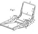
- La figure 1, de ces dessins, est une vue perspective d'un siège de véhicule selon l'invention dont les deux ossatures d'assise et de dossier sont ici séparées l'une de l'autre.
- Les figures 2 et 3 montrent le même siège avec ses deux ossatures montées l'une sur l'autre respectivement en vue latérale, portions coupées selon II-II figure 3, et en coupe transversale selon III-III figure 2.
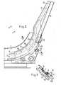
- Les figures 4 et 5 montrent une variante de siège selon l'envention, avec encore ses deux ossatures montées l'une sur l'autre, respectivement en vue latérale, portions couplées selon IV-IV figure 5, et en coupe transversale selon V-V figure 4.
- Figure 1 of these drawings is a perspective view of a vehicle seat according to the invention, the two seat and back frames are here separated from one another.
- FIGS. 2 and 3 show the same seat with its two frameworks mounted one on the other respectively in lateral view, portions cut according to II-II FIG. 3, and in cross section according to III-III FIG. 2.
- Figures 4 and 5 show a variant of a seat according to the invention, with still its two frames mounted one on the other, respectively in side view, portions coupled according to IV-IV Figure 5, and in cross section according to VV figure 4.
Dans chaque cas,
- - l'ossature d'assise est un cadre constitué par deux flasques métalliques verticaux 1 d'allure générale triangulaire effilée vers l'avant et entre- troisés transversalement par deux tubes horizontaux 2, 3,
- - et l'ossature de dossier comprend un arceau 4 dont les deux jambes peuvent être reliées par une entretoise horizontale transversale 5.
- - the seat frame is a frame made up of two vertical metallic flanges 1 general triangular tapered towards the front and interspersed transversely by two
horizontal tubes 2, 3,
- - and the back rest frame comprises a hoop 4, the two legs of which can be connected by a horizontal
transverse spacer 5.
On agence en outre certains éléments constitutifs de ces deux ossatures de façon telle qu'ils forment, de chaque côté du siège, une paire de profilés métalliques incurvés appartenant respectivement à l'ossature d'assise et à l'ossature de dossier et emboîtables l'un dans l'autre aux fins de glissement mutuel, ces profilés étant centrés sur un même axe horizontal transversal X.In addition, certain constituent elements of these two frames are arranged in such a way that they form, on each side of the seat, a pair of curved metal profiles belonging respectively to the seat frame and to the back frame and interlocking l 'one inside the other for the purpose of mutual sliding, these sections being centered on the same transverse horizontal axis X.
Cet axe X n'est disposé:
- - ni dans la zone arrière basse du siège, comme les axes des articulations classiques,
- - ni dans la zone, relativement haute et avancée, où se trouve le centre de courbure de l'arc de cercle passant respectivement par l'extrémité avant de l'assise, par le fond arrière de cette assise et par le sommet du dossier.
- - nor in the lower rear area of the seat, like the axes of conventional joints,
- - nor in the zone, relatively high and advanced, where the center of curvature of the arc of a circle lies, passing respectively by the front end of the seat, by the rear bottom of this seat and by the top of the backrest.
Ledit axe X est ici disposé au voisinage de l'axe de pivotement H des hanches de l'usager du siège (voir figure 2).Said axis X is here arranged in the vicinity of the pivot axis H of the hips of the seat user (see FIG. 2).
A titre illustratif, cet axe X est situé à une hauteur de l'ordre de 12 à 15 cm au-dessus du point le plus bas de la zone médiane de la surface de portage du coussin d'assise et à une distance horizontale de l'ordre de 15 à 20 cm en avant de la base de la zone médiane de la surface de portage du coussin du dossier.By way of illustration, this axis X is situated at a height of the order of 12 to 15 cm above the lowest point of the middle zone of the carrying surface of the seat cushion and at a horizontal distance from
L'intérêt présenté par le positionnement ainsi défini de l'axe X sera expliqué plus loin.The advantage presented by the positioning thus defined of the X axis will be explained later.
L'un des deux profilés incurvés de chaque paire est prévu de façon à envelopper l'autre sur plus de la moitié de son pourtour de façon telle qu'après le début de leur emboîtement mutuel, ces profilés ne puissent plus subir, l'un par rapport à l'autre, que des coulissement relatifs "circulaires", c'est-à-dire pour lesquels chaque point mobile se déplace selon un arc de cercle centré sur l'axe X.One of the two curved profiles of each pair is provided so as to wrap the other over more than half of its periphery in such a way that after the beginning of their mutual nesting, these profiles can no longer undergo, one relative to the other, only relative sliding "circular", that is to say for which each moving point moves in an arc centered on the axis X.
Pour les diverses positions de réglage, la portion mutuellement emboîtée des profilés incurvés correspond à un arc de cercle d'axe X relativement grand, cet arc étant généralement compris entre 45 et 90° et de préférance de l'ordre de 60°.For the various adjustment positions, the mutually nested portion of the curved sections corresponds to a relatively large arc of an axis X, this arc generally being between 45 and 90 ° and preferably of the order of 60 °.
Dans le premier mode de réalisation illustré sur les figures 1 à 3, l'un des profilés 6, lié à l'ossature de dossier, est une gouttière présentant un profil en C relativement fermé.In the first embodiment illustrated in Figures 1 to 3, one of the profiles 6, linked to the back frame, is a gutter having a relatively closed C profile.
L'autre profilé, dont le profil présente la forme générale d'un T, est constitué par un ressaut plat 7 s'étendant selon une portion de disque et faisant saillie sur l'un des flasques 1, ce ressaut étant réalisé par emboutissage dudit flasque et étant lui-même prolongé radialement, aussi bien en direction de l'axe X que dans la direction inverse, par des pattes 8 (figure 3) crevées dans les zones de raccordement dudit ressaut au reste du flasque.The other profile, whose profile has the general shape of a T, is constituted by a
Les deux séries de pattes coplanaires 8 ainsi formées sont elles-mêmes coiffées à demeure par des fourrures 9, 10 constitués en une matière plastique ou autre présentant un faible coefficient de forttement et une bonne résistance à l'usure.The two series of
Ce sont les deux fourrures 9 et 10 montées sur chaque ressaut 7 qui sont jointivement emboîtés à l'intérieur de la gouttière 6, ou plus précisément c'est cette dernière qui vient chevaucher jointivement lesdits joncs lors de l'emboîtement mutuel des deux profilés.These are the two
La gouttière 6 est avantageusement constituée par deux pièces courbes 61, 62 centrées sur l'axe X, soudées l'une sur l'autre aux points 101 et présentant chacune une section droite en J.The gutter 6 is advantageously constituted by two curved pieces 61 , 62 centered on the axis X, welded to each other at
L'une de ces pièces 61, en forme de baguette relativement étroite, comporte un prolongement rectiligne supérieur 11 orienté vers le haut et vers l'arrière et formant avec ladite pièce une sorte de faucille étirée.One of these parts 61 , in the form of a relatively narrow rod, has an upper
L'extrémité supérieure de ce prolongement 11 ist biseautée en 12 et soudée sur l'arceau 4 en une zone haute de ce dernier.The upper end of this
L'autre pièce 62, plus large que la pièce 61, se présente sous la forme générale d'une joue verticale à bord arrière rabattu et sa portion supérieure est soudée non seulement sur la pièce 61 et sur le bas de son prolongement supérieur 11, mais aussi sur le bas d'une jambe de l'arceau 4.The other part 62 , wider than the part 61 , is in the general form of a vertical cheek with folded rear edge and its upper portion is welded not only on the part 61 and on the bottom of its extension upper 11, but also on the bottom of one leg of the arch 4.
L'ensemble triangulé rigide ainsi formé présente une grande résistance aux déformations.The rigid triangulated assembly thus formed has great resistance to deformation.
Le montage de l'ossature de dossier sur l'ossature d'assise est effectué en faisant d'abord coïncider les axes des profilés 6 et 7, puis en emmanchant en bout "circulairement" les extrémités inférieures des gouttières 6 du dossier sur les extrémités supérieures des profilés 7 en T de l'assise de façon telle que chaque gouttière 6 enveloppe jointivement les deux fourrures 9 et 10 coiffant un ressaut 7 en pouvant glisser le long de celles-ci.The mounting of the back frame on the seat frame is carried out by first making the axes of the
Si aucune butée intermédiaire n'est prévue, l'ossature de dossier ainsi emboîtée sur l'ossature d'assise vient par gravité occuper sa position inférieure d'emboîtement maximum, position correspondant à l'inclinaison maximum du dossier sur la verticale et au contact mutuel de portées de fin de course prévues respectivement sur les profilés et/ou sur les ossatures.If no intermediate stop is provided, the back frame thus fitted onto the seat frame comes by gravity to occupy its lower position of maximum nesting, position corresponding to the maximum inclination of the back on the vertical and in contact mutual end-of-travel spans provided respectively on the profiles and / or on the frames.
En réalité, le degré de l'emboîtement mutuel en question est limité et réglé à volanté à l'aide d'un mécanisme de réglage et de verrouillage qui va être maintenant décrit.In reality, the degree of mutual interlocking in question is limited and adjusted to the wheel using an adjustment and locking mechanism which will now be described.
Du fait de l'emplacement particulier indiqué ci-dessus pour l'axe X, ce réglage du degré d'emboîtement "circulaire" mutuel des profilés courbes se traduit par un réglage de l'inclinaison du dossier autour de cet axe X, entraînant une modification naturelle de l'inclinaison du dos de la personne assise autour de ses hanches, et non pas par un simple raccourcissement ou allongement du dossier sans modification substantielle de son inclinaison d'ensemble.Because of the particular location indicated above for the X axis, this adjustment of the degree of mutual "circular" interlocking of the curved sections results in an adjustment of the inclination of the backrest around this X axis, resulting in a natural modification of the inclination of the back of the person seated around his hips, and not by a simple shortening or lengthening of the backrest without substantial modification of his overall inclination.
Le mécanisme de réglage et de verrouillage considéré comprend:
- -au moins une
crémaillère 13 s'étendant selon un arc de cercle centré sur l'axe X et solidaire de l'un des deux profilés courbes, - - un organe denté rotatif 14 porté par l'ossature solidaire de l'autre profilé courbe et propre à coopérer avec la
crémaillère 13, les rotations de cet organe étant commandées par une manette (non représentée) facilement accessible de la personne assise sur le siège, manette dont les rotations sont elles-mêmes transmises de toute manière désirable à une roue 15 (figure 3) solidaire duditorgane 14, - - et des moyens pour bloquer l'organe denté 14 en une pluralité de ses positions angulaires correspondant à autant d'inclinaisons différentes du dossier.
- at least one
rack 13 extending along an arc centered on the axis X and integral with one of the two curved sections, - - A
rotary toothed member 14 carried by the frame integral with the other curved profile and adapted to cooperate with therack 13, the rotations of this member being controlled by a lever (not shown) easily accessible to the person sitting on the seat , joystick whose rotations are themselves transmitted in any desirable manner to a wheel 15 (FIG. 3) integral with saidmember 14, - - And means for locking the
toothed member 14 in a plurality of its angular positions corresponding to as many different inclinations of the backrest.
Dans le mode de réalisation illustré, le nombre des crémaillères circulaires 13 est égal à deux et ces crémaillères sont constituées par des plaquettes métalliques découpées soudées sur les joues verticales des pièces 62 de façon telle que leurs dents soient orientées vers le bas et vers l'arrière, alors que les organes dentés 14, au nombre de deux également, sont solidaires d'une même barre rigide transversale 16 portée par l'ossature d'assise, à l'arrière de celle-ci, et terminée à ses deux extrémités par les roues 15.In the illustrated embodiment, the number of
Les organes dentés 14 peuvent présenter toute forme désirable: c'est ainsi qu'ils peuvent être constitués par des pignons associés à des moyens de verrouillage angulaire.The
Dans la construction illustrée, ces organes dentés 14 sont constitués chacun par deux pions cylindriques identiques d'axes parallèles à l'axe X et symétriques l'un de l'autre par rapport à l'axe de la barre 16, pions propres à coagir avec les dents des crémaillères 13.In the illustrated construction, these
De plus, la barre 16 est montée de façon à pouvoir rouler et glisser jointivement dans deux lumières 17 évidées respectivement dans les deux flasques 1 et allongées radialement par rapport à l'axe X, et des ressorts (non représentés) sont prévus pour solliciter constamment la barre 16 vers l'avant et vers le haut de façon à introduire les pions 14 au fond des encoches en regard des crémaillères correspondantes.In addition, the
Dans ces conditions, au repos, tous les pions sont logés au fond de telles encoches et le mécanisme est verrouillé.Under these conditions, at rest, all the pins are housed at the bottom of such notches and the mechanism is locked.
A partir d'une telle position de repos, les rotations de la manette de commande de la barre 16 se traduisent par des pivotements successifs de 180° de cette barre autour de chacun des couples de pions coaxiaux situés de chaque côté du siège, ces couples constituant à tour de rôle des tourillons fixes de pivotement pour ladite barre: à chacun de ces pivotement successifs correspond un coulissement de l'ossature de dossier vers le haut ou vers le bas, c'est-à-dire une réduction ou une augmentation de son inclinaison sur la verticale autour de l'axe X.From such a rest position, the rotations of the control lever of the
Ce mécanisme présente l'avantage d'assurer automatiquement un excellent verrouillage pour chacune de ses positions de réglage.This mechanism has the advantage of automatically ensuring excellent locking for each of its adjustment positions.
Dans la variante de construction représentée sur les figures 4 et 5, le profilé courbe faisant partie de l'ossature du dossier est constitué par un élément tubulaire 18 qui peut soit présenter un prolongement rectiligne supérieur 19 s'étendant vers le haut et vers l'arrière et soudé à l'arceau 4 comme le prolongement 11 ci-dessus, soit constituer lui-même un prolongement inférieur d'une jambe de cet arceau.In the construction variant shown in FIGS. 4 and 5, the curved profile forming part of the back frame is constituted by a
Le profilé courbe faisant partie de l'ossature d'assise est ici constitué par un tunnel curviligne 20 de section carrée.The curved profile forming part of the seat framework is here constituted by a
Ce tunnel est lui-même composé d'une rigole curviligne 20, de section droite rectangulaire emboutie dans un flasque 1 et d'un capot curvilgne 202 présentant en section droite la forme d'un oméga majuscule aplati dont les ailes sont soudées_par points 21 sur les bords de la rigole 20i.This tunnel is itself composed of a
Ce tunnel 20 est garni intérieurement de fourrures de glissement 22, 23 en forme de cornières curvilignes disposées dans deux coins opposés dudit tunnel, fourrures jouant ici le rôle des joncs 9 et 10 ci-dessus: les formes et épaisseurs de ces fourrures sont choisies de façon telles qu'elles offrent au tube 18 un contact glissant selon quatre plaques étroites s'étendant chacune selon un arc de cercle centré sur l'axe X.This
On retrouve ici les plaques découpées 13 servant de crémaillères et propres à coopérer avec des pions 14 exactement comme dans le version précédente: chacune de ces plaques 13 est ici rapportée à l'aide de vis 24 sur une portion légèrement aplatie du tube 18 et chaque tunnel curviligne 20 est ajouré par une large fenêtre 25 livrant passage à la plaque-crémaillère 13 correspondante.Here we find the
Il est à noter que, dans chaque cas, les profilés courbes mutuellement emboîtés remplissent un double rôle: ils servent à la fois de "coulisses" ou éléments de glissières propres à guider les déplacements du dossier, et d'éléments d'armature résistants consitutifs des ossatures ou cadres de dossier et d'assise.It should be noted that, in each case, the mutually interlocking curved profiles fulfill a double role: they serve both as "slides" or elements of slides suitable for guiding the movements of the backrest, and as resistant reinforcing elements back and seat frames or frames.
Il s'ensuite une simplification et un allègement.It follows a simplification and a reduction.
Dans chaque cas également, la surface de contact mutuel des profilés curvilignes mutuellement emboîtés s'étend circulairement sur un arc relativement étendu, généralement supérieur à 45° et par exemple de l'ordre de 60°, et sur une relativement grande longueur, la ligne moyenne des tronçons emboîtés des profilés mesurant généralement 15 à 25 cm, étant notamment de l'ordre de 20 cm.In each case also, the mutual contact surface of the mutually nested curvilinear profiles extends circularly over a relatively extended arc, generally greater than 45 ° and for example of the order of 60 °, and over a relatively great length, the line average of the nested sections of the profiles generally measuring 15 to 25 cm, being in particular of the order of 20 cm.
Au contraire, la ligne correspondant à la section droite de ladite ossature de contact mutuel s'étend sur une longueur beaucoup plus faible, généralement inférieure.à 10 cm et plutôt comprise entre 3 et 7 cm.On the contrary, the line corresponding to the cross section of said mutual contact framework extends over a much shorter length, generally less than 10 cm and rather between 3 and 7 cm.
En d'autres termes, la section droite des profilés courbes considérés est relativement faiblé pour une surface de contact mutuel donnée, ce qui conduit toutes choses égales par ailleurs à un faible poids et à un faible prix de revient.In other words, the cross section of the curved sections considered is relatively small for a given mutual contact surface, which leads, all other things being equal, to low weight and low cost price.
Il est à noter par ailleurs que la formule proposée permet de supprimer complètement l'arbre d'articulation habituel et donc de supprimer par le fait même les "points durs" qui correspondaient à la présence de cet arbre à la base arrière de l'assise: cette suppression permet de réaliser une matelassure de garnissage plus profonde dans cette zone.It should also be noted that the proposed formula makes it possible to completely remove the usual articulation tree and therefore to delete by the same fact the "hard points" which corresponded to the presence of this tree at the rear base of the seat. : this deletion allows a deeper padding in this area.
Claims (4)
Applications Claiming Priority (2)
| Application Number | Priority Date | Filing Date | Title |
|---|---|---|---|
| FR8006769AFR2478982A1 (en) | 1980-03-26 | 1980-03-26 | IMPROVEMENTS ON SEATS WITH ADJUSTABLE RECLINING BACKREST |
| FR8006769 | 1980-03-26 |
Publications (3)
| Publication Number | Publication Date |
|---|---|
| EP0036824A2 EP0036824A2 (en) | 1981-09-30 |
| EP0036824A3 EP0036824A3 (en) | 1982-01-20 |
| EP0036824B1true EP0036824B1 (en) | 1986-12-10 |
Family
ID=9240148
Family Applications (1)
| Application Number | Title | Priority Date | Filing Date |
|---|---|---|---|
| EP81400461AExpiredEP0036824B1 (en) | 1980-03-26 | 1981-03-24 | Seats with back rest having adjustable inclination |
Country Status (7)
| Country | Link |
|---|---|
| US (1) | US4386805A (en) |
| EP (1) | EP0036824B1 (en) |
| JP (2) | JPS576615A (en) |
| AU (1) | AU540733B2 (en) |
| DE (1) | DE3175694D1 (en) |
| ES (1) | ES267159Y (en) |
| FR (1) | FR2478982A1 (en) |
Families Citing this family (29)
| Publication number | Priority date | Publication date | Assignee | Title |
|---|---|---|---|---|
| DE3319813A1 (en)* | 1983-02-19 | 1984-08-23 | C. Rob. Hammerstein Gmbh, 5650 Solingen | HEADSTOCK ADJUSTMENT, ESPECIALLY FOR TILT ADJUSTMENT OF MOTOR VEHICLE SEATS |
| AU573278B2 (en)* | 1984-12-10 | 1988-06-02 | Tachikawa Spring Co. Ltd. | Unlocking mechanism for vehicle seat |
| FR2594760B1 (en)* | 1986-02-21 | 1989-11-10 | Renault | SEAT FRAME WITH ASSEMBLED CONSTRUCTION MODULES |
| NO160896C (en)* | 1986-05-09 | 1989-06-14 | Jurek Buchacz | ADJUSTABLE SEATING DEVICE. |
| US4795212A (en)* | 1988-01-29 | 1989-01-03 | Herman Miller, Inc. | Chair back adjustment |
| JP2719605B2 (en)* | 1988-07-19 | 1998-02-25 | アイシン精機株式会社 | Reclining adjuster |
| US5074621A (en)* | 1989-11-30 | 1991-12-24 | Systems Furniture Company | Chair back seat construction |
| DE4135948C2 (en)* | 1991-10-31 | 1993-12-23 | Rolf Voelkle | Chair, in particular office swivel chair |
| US5240265A (en)* | 1992-10-23 | 1993-08-31 | Huang Ming Tai | Joint for mounting a backrest support on a stroller frame |
| US5645318A (en)* | 1996-05-29 | 1997-07-08 | Lear Corporation | Seat back support connection |
| US5918935A (en)* | 1997-06-03 | 1999-07-06 | Stulik; Edward L. | Reclining chair |
| USD449813S1 (en) | 2000-03-20 | 2001-10-30 | James K. Bentley | Removable rear seat support strut for sport utility vehicles |
| USD467858S1 (en) | 2000-10-30 | 2002-12-31 | Ronald Douglas Misch | Armrest conversion unit |
| US6616231B2 (en) | 2001-06-15 | 2003-09-09 | Hon Technology Inc. | Multi-position tilt-limiting mechanism |
| US6666505B2 (en)* | 2002-04-23 | 2003-12-23 | Graco Children's Products Inc. | Reclining child seat |
| US20050017561A1 (en)* | 2003-07-21 | 2005-01-27 | Burmeister Richard F. | Seat, seat recliner mechanism, and seat recliner system |
| US7909407B2 (en)* | 2007-06-07 | 2011-03-22 | Lear Corporation | Vehicle seat connection |
| DE102007050091A1 (en)* | 2007-10-19 | 2009-04-23 | GM Global Technology Operations, Inc., Detroit | Vehicle seat with a rotating back section |
| DE102008011309B3 (en)* | 2008-02-27 | 2009-06-04 | Thonet Gmbh | office chair |
| USD654291S1 (en) | 2008-05-26 | 2012-02-21 | Steelcase Inc. | Seating unit |
| AU2009258164A1 (en) | 2008-05-26 | 2009-12-17 | Steelcase Inc. | Conforming back for a seating unit |
| AU323998S (en) | 2008-05-26 | 2009-01-19 | Steelcase Inc | Seating unit |
| US7841664B2 (en)* | 2008-06-04 | 2010-11-30 | Steelcase Inc. | Chair with control system |
| JP5485534B2 (en)* | 2008-10-29 | 2014-05-07 | 株式会社岡村製作所 | Chair |
| US7708344B1 (en)* | 2008-10-31 | 2010-05-04 | Midmark Corporation | Patient chair with locking assembly |
| US9604553B2 (en)* | 2012-12-11 | 2017-03-28 | Ford Global Technologies, Llc | Virtual H-point seat back system |
| USD696545S1 (en) | 2013-07-30 | 2013-12-31 | Steelcase, Inc. | Rear surface of a chair back |
| CN209073846U (en)* | 2018-05-11 | 2019-07-09 | 杭州中泰实业集团有限公司 | A kind of Revolving chair tray that slider-crank mechanism is adjusted |
| US11589678B2 (en) | 2019-01-17 | 2023-02-28 | Hni Technologies Inc. | Chairs including flexible frames |
Family Cites Families (12)
| Publication number | Priority date | Publication date | Assignee | Title |
|---|---|---|---|---|
| US137091A (en)* | 1873-03-25 | Improvement in tilting-chairs | ||
| US1970577A (en)* | 1931-05-21 | 1934-08-21 | Edward P Farrell | Adjustable chair |
| US2299538A (en)* | 1939-11-16 | 1942-10-20 | Goldstein Jacob | Chair with combined rocking and tilting action |
| US2430604A (en)* | 1944-02-16 | 1947-11-11 | John M Dorton | Reclining spring supported back rest |
| US3044830A (en)* | 1959-09-03 | 1962-07-17 | Daimler Benz Ag | Back rest adjusting device |
| US3445143A (en)* | 1967-05-22 | 1969-05-20 | Swenson Corp | Adjustable slide support |
| DE1923159C3 (en)* | 1969-05-07 | 1974-02-14 | Ford-Werke Ag, 5000 Koeln | Adjustable seat for automobiles |
| AT296532B (en)* | 1970-10-30 | 1972-02-25 | Wiesner Hager Kg | Device for adjusting the inclination of the backrest of armchairs, in particular office armchairs |
| US3672625A (en)* | 1971-03-01 | 1972-06-27 | Ford Motor Co | Position locator for an adjustable seat supporting assembly |
| DE2642091A1 (en)* | 1976-09-18 | 1978-03-23 | Wilde & Spieth | Office chair with adaptable backrest - has esp. disposed swivel axis ensuring automatic adjustment to all body movements |
| DE2735583A1 (en)* | 1977-08-06 | 1979-02-15 | Wilde & Spieth | Office chair with adjustable seat and backrest - has lever-operated bolt engaging in toothed segments on frame |
| FR2469316A1 (en)* | 1979-11-14 | 1981-05-22 | Faure Bertrand | IMPROVEMENTS ON VEHICLE SEATS INCLUDING A HULL FRAME |
- 1980
- 1980-03-26FRFR8006769Apatent/FR2478982A1/enactiveGranted
- 1981
- 1981-03-24DEDE8181400461Tpatent/DE3175694D1/ennot_activeExpired
- 1981-03-24USUS06/246,948patent/US4386805A/ennot_activeExpired - Fee Related
- 1981-03-24EPEP81400461Apatent/EP0036824B1/ennot_activeExpired
- 1981-03-25AUAU68737/81Apatent/AU540733B2/ennot_activeCeased
- 1981-03-25ESES1981267159Upatent/ES267159Y/ennot_activeExpired
- 1981-03-26JPJP4468481Apatent/JPS576615A/enactivePending
- 1990
- 1990-10-31JPJP1990114685Upatent/JPH047793Y2/janot_activeExpired
Also Published As
| Publication number | Publication date |
|---|---|
| AU540733B2 (en) | 1984-11-29 |
| AU6873781A (en) | 1981-10-01 |
| EP0036824A2 (en) | 1981-09-30 |
| EP0036824A3 (en) | 1982-01-20 |
| JPH047793Y2 (en) | 1992-02-28 |
| JPH03101243U (en) | 1991-10-22 |
| FR2478982A1 (en) | 1981-10-02 |
| US4386805A (en) | 1983-06-07 |
| FR2478982B1 (en) | 1985-04-12 |
| ES267159Y (en) | 1983-08-16 |
| ES267159U (en) | 1983-02-16 |
| DE3175694D1 (en) | 1987-01-22 |
| JPS576615A (en) | 1982-01-13 |
Similar Documents
| Publication | Publication Date | Title |
|---|---|---|
| EP0036824B1 (en) | Seats with back rest having adjustable inclination | |
| EP0029763B1 (en) | Vehicle seat with shell frame work and adjustable inclination | |
| EP0888926B1 (en) | Vehicle seat with a neck protection device in case of rear impact | |
| CH626522A5 (en) | Tilting mounting for a chair seat | |
| FR2775638A1 (en) | FRAME SYSTEM FOR SEAT | |
| EP0575243B1 (en) | Vehicle seat with multiple adjustment | |
| WO1996004823A1 (en) | Novel office chair structure | |
| FR2593686A1 (en) | STACKABLE ARMCHAIR WITH A RECLINER FOLDABLE AND FOLDABLE | |
| EP0028564B1 (en) | Vehicle seat with at least a one-piece seat portion | |
| WO1997036520A1 (en) | Chair consisting of interlocking elements | |
| EP1488770B1 (en) | Stand-up chair with self-modifying tilting of the backrest | |
| EP0681854B1 (en) | Exercising apparatus | |
| FR3097837A1 (en) | Rail intended in particular for fixing a seat in an aircraft, and locking mechanism intended in particular for fixing a seat on this rail | |
| EP0572345B1 (en) | Armrest for a front seat of a vehicle | |
| FR3149836A1 (en) | Vehicle comprising a rear seat with a backrest that can be adjusted to at least four positions | |
| WO1999017638A1 (en) | Furniture piece made up of constructible elements | |
| FR2730146A1 (en) | Arm-chair with adjustable inclination of back and seat | |
| BE538624A (en) | ||
| FR2660234A1 (en) | Adjustable mould for prefabricating staircases | |
| FR2758247A1 (en) | School chair | |
| FR2681825A3 (en) | Inclinable seat for a motor vehicle | |
| FR2621281A1 (en) | Improvements to vehicle seats with adjustable backrest | |
| BE399957A (en) | ||
| CH663527A5 (en) | SOFA. | |
| FR2525092A1 (en) | Tilt adjustment for seat - consists of four parallel axles on base with vertical link controlled by pawls |
Legal Events
| Date | Code | Title | Description |
|---|---|---|---|
| PUAI | Public reference made under article 153(3) epc to a published international application that has entered the european phase | Free format text:ORIGINAL CODE: 0009012 | |
| AK | Designated contracting states | Designated state(s):BE DE GB IT NL SE | |
| PUAL | Search report despatched | Free format text:ORIGINAL CODE: 0009013 | |
| AK | Designated contracting states | Designated state(s):BE DE GB IT NL SE | |
| 17P | Request for examination filed | Effective date:19820125 | |
| ITF | It: translation for a ep patent filed | ||
| GRAA | (expected) grant | Free format text:ORIGINAL CODE: 0009210 | |
| AK | Designated contracting states | Kind code of ref document:B1 Designated state(s):BE DE GB IT NL SE | |
| REF | Corresponds to: | Ref document number:3175694 Country of ref document:DE Date of ref document:19870122 | |
| PLBE | No opposition filed within time limit | Free format text:ORIGINAL CODE: 0009261 | |
| STAA | Information on the status of an ep patent application or granted ep patent | Free format text:STATUS: NO OPPOSITION FILED WITHIN TIME LIMIT | |
| 26N | No opposition filed | ||
| PGFP | Annual fee paid to national office [announced via postgrant information from national office to epo] | Ref country code:DE Payment date:19920321 Year of fee payment:12 | |
| PGFP | Annual fee paid to national office [announced via postgrant information from national office to epo] | Ref country code:GB Payment date:19930316 Year of fee payment:13 | |
| PGFP | Annual fee paid to national office [announced via postgrant information from national office to epo] | Ref country code:SE Payment date:19930323 Year of fee payment:13 | |
| ITTA | It: last paid annual fee | ||
| PGFP | Annual fee paid to national office [announced via postgrant information from national office to epo] | Ref country code:NL Payment date:19930331 Year of fee payment:13 | |
| PGFP | Annual fee paid to national office [announced via postgrant information from national office to epo] | Ref country code:BE Payment date:19930414 Year of fee payment:13 | |
| PG25 | Lapsed in a contracting state [announced via postgrant information from national office to epo] | Ref country code:DE Effective date:19931201 | |
| PG25 | Lapsed in a contracting state [announced via postgrant information from national office to epo] | Ref country code:GB Effective date:19940324 | |
| PG25 | Lapsed in a contracting state [announced via postgrant information from national office to epo] | Ref country code:SE Free format text:LAPSE BECAUSE OF NON-PAYMENT OF DUE FEES Effective date:19940325 | |
| PG25 | Lapsed in a contracting state [announced via postgrant information from national office to epo] | Ref country code:BE Effective date:19940331 | |
| BERE | Be: lapsed | Owner name:SOC. INDUSTRIELLE BERTRAND FAURE Effective date:19940331 | |
| PG25 | Lapsed in a contracting state [announced via postgrant information from national office to epo] | Ref country code:NL Effective date:19941001 | |
| NLV4 | Nl: lapsed or anulled due to non-payment of the annual fee | ||
| GBPC | Gb: european patent ceased through non-payment of renewal fee | Effective date:19940324 | |
| EUG | Se: european patent has lapsed | Ref document number:81400461.0 Effective date:19941010 |