EP0033072A1 - Apparatus with a device for securing a guide bar - Google Patents
Apparatus with a device for securing a guide barDownload PDFInfo
- Publication number
- EP0033072A1 EP0033072A1EP81100121AEP81100121AEP0033072A1EP 0033072 A1EP0033072 A1EP 0033072A1EP 81100121 AEP81100121 AEP 81100121AEP 81100121 AEP81100121 AEP 81100121AEP 0033072 A1EP0033072 A1EP 0033072A1
- Authority
- EP
- European Patent Office
- Prior art keywords
- guide rod
- eccentric
- guide bar
- bore
- securing
- Prior art date
- Legal status (The legal status is an assumption and is not a legal conclusion. Google has not performed a legal analysis and makes no representation as to the accuracy of the status listed.)
- Withdrawn
Links
Images
Classifications
- F—MECHANICAL ENGINEERING; LIGHTING; HEATING; WEAPONS; BLASTING
- F16—ENGINEERING ELEMENTS AND UNITS; GENERAL MEASURES FOR PRODUCING AND MAINTAINING EFFECTIVE FUNCTIONING OF MACHINES OR INSTALLATIONS; THERMAL INSULATION IN GENERAL
- F16B—DEVICES FOR FASTENING OR SECURING CONSTRUCTIONAL ELEMENTS OR MACHINE PARTS TOGETHER, e.g. NAILS, BOLTS, CIRCLIPS, CLAMPS, CLIPS OR WEDGES; JOINTS OR JOINTING
- F16B2/00—Friction-grip releasable fastenings
- F16B2/02—Clamps, i.e. with gripping action effected by positive means other than the inherent resistance to deformation of the material of the fastening
- F16B2/18—Clamps, i.e. with gripping action effected by positive means other than the inherent resistance to deformation of the material of the fastening using cams, levers, eccentrics, or toggles
- F16B2/185—Clamps, i.e. with gripping action effected by positive means other than the inherent resistance to deformation of the material of the fastening using cams, levers, eccentrics, or toggles using levers
- B—PERFORMING OPERATIONS; TRANSPORTING
- B25—HAND TOOLS; PORTABLE POWER-DRIVEN TOOLS; MANIPULATORS
- B25G—HANDLES FOR HAND IMPLEMENTS
- B25G3/00—Attaching handles to the implements
- B25G3/02—Socket, tang, or like fixings
- B25G3/12—Locking and securing devices
- B25G3/20—Locking and securing devices comprising clamping or contracting means acting concentrically on the handle or socket
- B—PERFORMING OPERATIONS; TRANSPORTING
- B25—HAND TOOLS; PORTABLE POWER-DRIVEN TOOLS; MANIPULATORS
- B25G—HANDLES FOR HAND IMPLEMENTS
- B25G3/00—Attaching handles to the implements
- B25G3/02—Socket, tang, or like fixings
- B25G3/12—Locking and securing devices
- B25G3/26—Locking and securing devices comprising nails, screws, bolts, or pins traversing or entering the socket
Definitions
- the inventionrelates to a device with a fastening arrangement for a guide rod which can be inserted into a corresponding bore provided on the device.
- a vacuum cleaneris known in which a clamping body is arranged in the bore for the guide tube. After inserting the guide tube, the clamping body is pressed against the guide tube by means of screws. For this purpose, the screws are passed through corresponding holes in the wall of the guide tube and screwed into threaded holes in the clamping body.
- the fastening of the guide tubeis therefore relatively cumbersome and cannot be carried out without tools.
- this type of attachmentis only suitable for tubular guide rods.
- the inventionhas for its object to design a device with a mounting arrangement for a guide rod so that the guide rod can be easily attached to the device without tools.
- an eccentric provided with an actuating leveris arranged on the device in the region of the bore and can be brought into a clamped connection with the guide rod.
- a form-fitting attachmentis achieved in that a recess is provided on the guide rod, in which the eccentric engages in its clamped position.
- secure attachment of the guide rodalso in that a resilient tongue is provided in the wall of the bore and can be pressed against the guide rod by the eccentric.
- 1denotes the housing of a device, for example a vacuum cleaner.
- a bore 2is formed on this housing, into each of which a guide rod 3 or 4 is inserted.
- An eccentric 6provided with an actuating lever 5 is pivotably attached to the housing in the area of the bore 2. The eccentric 6 is shown in the fastening position. The eccentric position in which the guide rod is released from the eccentric 6 is indicated by dashed lines.
- the guide rod 3has a recess 7 formed as a circumferential groove, into which the eccentric 6 lies with its greatest projection. In this way, a positive fastening of the guide rod 3 is achieved.
- a resilient tongue 8is provided on the wall of the bore 2 and is pressed by the eccentric 6 against the guide rod 4. The guide rod 4 is thus held in the bore 2 by clamping action.
- the guide rod 3 or 4is released in each case by pivoting the actuating lever 5 into the position indicated by dashed lines.
Landscapes
- Engineering & Computer Science (AREA)
- Mechanical Engineering (AREA)
- General Engineering & Computer Science (AREA)
- Clamps And Clips (AREA)
Abstract
Description
Translated fromGermanDie Erfindung bezieht sich auf ein Gerät mit einer Befestigungsanordnung für eine Führungsstange, die in eine entsprechende, am Gerät vorgesehene Bohrung einsteckbar ist.The invention relates to a device with a fastening arrangement for a guide rod which can be inserted into a corresponding bore provided on the device.
Durch das DE-GM 78 37 444 ist ein Staubsauger bekannt, bei dem in der Bohrung für das Führungsrohr ein Klemmkörper angeordnet ist. Nach dem Einstecken des Führungsrohres wird der Klemmkörper mittels Schrauben gegen das Führungsrohr gepreßt. Hierzu werden die Schrauben durch entsprechende Bohrungen in der Wand des Führungsrohres hindurchgeführt und in Gewindelöcher des Klemmkörpers eingeschraubt. Bei diesem bekannten Staubsauger ist das Befestigen des Führungsrohres somit relativ umständlich und kann nicht ohne Werkzeug ausgeführt werden. Außerdem eignet sich diese Befestigungsart nur für rohrförmige Führungsstangen.From DE-GM 78 37 444 a vacuum cleaner is known in which a clamping body is arranged in the bore for the guide tube. After inserting the guide tube, the clamping body is pressed against the guide tube by means of screws. For this purpose, the screws are passed through corresponding holes in the wall of the guide tube and screwed into threaded holes in the clamping body. In this known vacuum cleaner, the fastening of the guide tube is therefore relatively cumbersome and cannot be carried out without tools. In addition, this type of attachment is only suitable for tubular guide rods.
Der Erfindung liegt die Aufgabe zugrunde, ein Gerät mit einer Befestigungsanordnung für eine Führungsstange so auszubilden, daß die Führungsstange ohne Werkzeug in einfacher Weise an dem Gerät befestigt werden kann.The invention has for its object to design a device with a mounting arrangement for a guide rod so that the guide rod can be easily attached to the device without tools.
Die Lösung der gestellten Aufgabe gelingt nach der Erfindurch dadurch, daß am Gerät im Bereich der Bohrung ein mit einem Betätigungshebel versehener Exzenter angeordnet ist, der mit der Führungsstange in Klemmverbindung bringbar ist.The object is achieved according to the invention in that an eccentric provided with an actuating lever is arranged on the device in the region of the bore and can be brought into a clamped connection with the guide rod.
Eine formschlüssige Befestigung wird dadurch erreicht, daß an der Führungsstange eine Vertiefung vorgesehen ist, in die der Exzenter in seiner Klemmstellung eingreift. Nach einer weiteren Ausgestaltung der Erfindung ergibt sich eine sichere Befestigung der Führungsstange auch dadurch, daß in der Wand der Bohrung eine federnde Zunge vorgesehen und durch den Exzenter an die Führungsstange anpreßbar ist.A form-fitting attachment is achieved in that a recess is provided on the guide rod, in which the eccentric engages in its clamped position. According to a further embodiment of the invention secure attachment of the guide rod also in that a resilient tongue is provided in the wall of the bore and can be pressed against the guide rod by the eccentric.
Anhand eines in der Zeichnung dargestellten Ausführungsbeispiels wird der Anmeldungsgegenstand nachfolgend näher beschrieben. Es zeigt
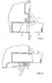
- Fig. 1 einen Detailschnitt eines Gerätes, bei dessen Befestigungsanordnung ein Exzenter in eine an der Führungsstange ausgebildete Nut eingreift,
- Fig. 2 einen Detailschnitt eines Gerätes, bei dessen Befestigungsanordnung eine in der Bohrung angeordnete Zunge mittels des Exzenters an die Führungsstange anpreßbar ist.
- 1 is a detail section of a device, in the mounting arrangement of which an eccentric engages in a groove formed on the guide rod,
- Fig. 2 shows a detail section of a device, in the mounting arrangement of which a tongue arranged in the bore can be pressed onto the guide rod by means of the eccentric.
In beiden Figuren ist mit 1 jeweils das Gehäuse eines Gerätes, beispielsweise eines Staubsaugers, bezeichnet. An diesem Gehäuse ist eine Bohrung 2 ausgebildet, in welche jeweils eine Führungsstange 3 bzw. 4 eingesteckt ist. Am Gehäuse ist im Bereich der Bohrung 2 ein mit einem Betätigungshebel 5 versehener Exzenter 6 verschwenkbar befestigt. Der Exzenter 6 ist jeweils in der Befestigungsstellung dargestellt. Durch gestrichelte Linien ist die Exzenterstellung angedeutet, in der die Führungsstange jeweils vom Exzenter 6 freigegeben ist.In both figures, 1 denotes the housing of a device, for example a vacuum cleaner. A
Bei dem Ausführungsbeispiel nach Fig. 1 weist die Führungsstange 3 eine als umlaufende Nut ausgebildete Vertiefung 7 auf, in die sich der Exzenter 6 mit seiner größten Ausladung einlegt. Hierdurch wird eine formschlüssige Befestigung der Führungsstange 3 erreicht. Bei der Darstellung nach Fig. 2 ist an der.Wand der Bohrung 2 eine federnde Zunge 8 vorgesehen, welche durch den Exzenter 6 gegen die Führungsstange 4 gepreßt wird. Die Führungsstange 4 wird somit durch Klemmwirkung in der Bohrung 2 gehalten.In the exemplary embodiment according to FIG. 1, the guide rod 3 has a
Das Lösen der Führungsstange 3 bzw. 4 erfolgt jeweils durch ein Verschwenken des Betätigungshebels 5 in die durch gestrichelte Linien angedeutete Stellung.The guide rod 3 or 4 is released in each case by pivoting the actuating
Claims (3)
Translated fromGermanApplications Claiming Priority (2)
| Application Number | Priority Date | Filing Date | Title |
|---|---|---|---|
| DE19808001690DE8001690U1 (en) | 1980-01-23 | 1980-01-23 | DEVICE WITH A FASTENING ARRANGEMENT FOR A GUIDE ROD |
| DE8001690U | 1980-01-23 |
Publications (1)
| Publication Number | Publication Date |
|---|---|
| EP0033072A1true EP0033072A1 (en) | 1981-08-05 |
Family
ID=6712228
Family Applications (1)
| Application Number | Title | Priority Date | Filing Date |
|---|---|---|---|
| EP81100121AWithdrawnEP0033072A1 (en) | 1980-01-23 | 1981-01-09 | Apparatus with a device for securing a guide bar |
Country Status (2)
| Country | Link |
|---|---|
| EP (1) | EP0033072A1 (en) |
| DE (1) | DE8001690U1 (en) |
Cited By (8)
| Publication number | Priority date | Publication date | Assignee | Title |
|---|---|---|---|---|
| EP0118582A1 (en)* | 1983-03-17 | 1984-09-19 | LEIFHEIT Aktiengesellschaft | Separable fixing device for the handles of tools |
| US4514708A (en)* | 1982-02-26 | 1985-04-30 | Motorola, Inc. | Quick disconnect waveguide locking mechanism |
| DE3722219A1 (en)* | 1987-07-04 | 1989-01-12 | Langenstein Feld Garten | WORKING DEVICE, LIKE GARDEN DEVICE, FIELD DEVICE, CLEANING DEVICE OR THE LIKE. |
| US5348415A (en)* | 1990-08-17 | 1994-09-20 | Ergonomiprodukter I Bodafors Ab | Locking device |
| EP0777557B1 (en)* | 1994-08-30 | 1998-06-10 | WOLF-Geräte GmbH Vertriebsgesellschaft KG | Guiding stem for gardening tools |
| EP0834451A3 (en)* | 1996-10-01 | 1999-03-17 | Sunbum Pty Limited | Removable surf fin system |
| US6821173B2 (en) | 2001-11-13 | 2004-11-23 | Sunbum Pty., Ltd. | Removable and adjustable surf fin system |
| EP2813447A1 (en)* | 2013-06-13 | 2014-12-17 | Foshan Ideal Co., Ltd. | Clamping devices |
Citations (3)
| Publication number | Priority date | Publication date | Assignee | Title |
|---|---|---|---|---|
| DE1660720U (en)* | 1953-06-03 | 1953-08-06 | Martin Gehendges O H G | HANDLE FASTENING FOR AEXTE AND THE LIKE |
| US2849249A (en)* | 1955-10-20 | 1958-08-26 | Annette E Fridolph | Clamping device |
| CH391387A (en)* | 1960-12-01 | 1965-04-30 | Heinrich Dipl Ing Wuester | Device for the mutual clamping of telescopic pipes, in particular the stick pipe parts of garden umbrellas or the like |
- 1980
- 1980-01-23DEDE19808001690patent/DE8001690U1/ennot_activeExpired
- 1981
- 1981-01-09EPEP81100121Apatent/EP0033072A1/ennot_activeWithdrawn
Patent Citations (3)
| Publication number | Priority date | Publication date | Assignee | Title |
|---|---|---|---|---|
| DE1660720U (en)* | 1953-06-03 | 1953-08-06 | Martin Gehendges O H G | HANDLE FASTENING FOR AEXTE AND THE LIKE |
| US2849249A (en)* | 1955-10-20 | 1958-08-26 | Annette E Fridolph | Clamping device |
| CH391387A (en)* | 1960-12-01 | 1965-04-30 | Heinrich Dipl Ing Wuester | Device for the mutual clamping of telescopic pipes, in particular the stick pipe parts of garden umbrellas or the like |
Cited By (10)
| Publication number | Priority date | Publication date | Assignee | Title |
|---|---|---|---|---|
| US4514708A (en)* | 1982-02-26 | 1985-04-30 | Motorola, Inc. | Quick disconnect waveguide locking mechanism |
| EP0118582A1 (en)* | 1983-03-17 | 1984-09-19 | LEIFHEIT Aktiengesellschaft | Separable fixing device for the handles of tools |
| DE3722219A1 (en)* | 1987-07-04 | 1989-01-12 | Langenstein Feld Garten | WORKING DEVICE, LIKE GARDEN DEVICE, FIELD DEVICE, CLEANING DEVICE OR THE LIKE. |
| EP0298270A3 (en)* | 1987-07-04 | 1990-12-27 | Max Langenstein Feld- Und Gartengerate Gmbh & Co. | Tool such as gardening tool, farming tool, cleaning tool or the like |
| US5348415A (en)* | 1990-08-17 | 1994-09-20 | Ergonomiprodukter I Bodafors Ab | Locking device |
| EP0777557B1 (en)* | 1994-08-30 | 1998-06-10 | WOLF-Geräte GmbH Vertriebsgesellschaft KG | Guiding stem for gardening tools |
| EP0834451A3 (en)* | 1996-10-01 | 1999-03-17 | Sunbum Pty Limited | Removable surf fin system |
| US5975974A (en)* | 1996-10-01 | 1999-11-02 | Sunbum Pty. Limited | Removable surf fin system |
| US6821173B2 (en) | 2001-11-13 | 2004-11-23 | Sunbum Pty., Ltd. | Removable and adjustable surf fin system |
| EP2813447A1 (en)* | 2013-06-13 | 2014-12-17 | Foshan Ideal Co., Ltd. | Clamping devices |
Also Published As
| Publication number | Publication date |
|---|---|
| DE8001690U1 (en) | 1980-04-24 |
Similar Documents
| Publication | Publication Date | Title |
|---|---|---|
| DE3206789C2 (en) | Articulated support arm | |
| DE69903094T2 (en) | clamping device | |
| DE98898T1 (en) | DEVICE FOR MUTUAL FIXING OF RODS IN SELECTED POSITIONS. | |
| EP0316371A1 (en) | Device for adjusting a vertebral column. | |
| DE2814818A1 (en) | SECURITY ORGANIZATION | |
| DE2630498C3 (en) | Adjustable holder | |
| EP0033072A1 (en) | Apparatus with a device for securing a guide bar | |
| DE6600861U (en) | SCREW CONNECTION, IN PARTICULAR FOR FASTENING HARNESS TOOLS TO A SUPPORT BAR | |
| EP0657217A1 (en) | Laboratory apparatus with a socket for a support rod | |
| DE29913855U1 (en) | Adjustment device for a chair back | |
| DE479663T1 (en) | DOOR FASTENER FOR VEHICLES. | |
| DE8901019U1 (en) | Mounting device for a radio device that can be removably attached to a wall | |
| DE69300737T2 (en) | Clamping device. | |
| AT402472B (en) | DEVICE FOR DETACHABLE FASTENING OF A CLEANING DEVICE LIKE A BRUSH BETWEEN TWO CLAMPING JAWS | |
| DE2652759A1 (en) | RELEASABLE CONNECTION BETWEEN A DORN AND THE DORN BAR OF AN INCLINED ROLLING MILL | |
| DE1905379B2 (en) | SCREWLESS CLAMP | |
| EP0284946B1 (en) | Stethoscope | |
| DE3303414C2 (en) | Method and device for the electrical welding of contra-angle handpieces to a workpiece | |
| DE858932C (en) | Rotatable handle for pulling the control wires on bicycles with auxiliary engines, motorcycles and other vehicles | |
| DE2427714A1 (en) | Sliding and flexible load bearing element - has coil spring and piston to support one part of a machine from another | |
| DE803319C (en) | Method and device for producing a firm connection between two parts | |
| DE3443505C2 (en) | ||
| DE1114558B (en) | Earthing device for clamping to objects to be earthed, in particular to electrical overhead lines, in high-voltage and high-voltage systems | |
| DE832338C (en) | Device for adjusting movable parts | |
| DE1256901B (en) | Device for quick attachment of cameras or the like on tripods |
Legal Events
| Date | Code | Title | Description |
|---|---|---|---|
| PUAI | Public reference made under article 153(3) epc to a published international application that has entered the european phase | Free format text:ORIGINAL CODE: 0009012 | |
| AK | Designated contracting states | Designated state(s):DE FR NL SE | |
| STAA | Information on the status of an ep patent application or granted ep patent | Free format text:STATUS: THE APPLICATION IS DEEMED TO BE WITHDRAWN | |
| 18D | Application deemed to be withdrawn | Effective date:19820710 | |
| RIN1 | Information on inventor provided before grant (corrected) | Inventor name:KESS, HERBERT |