EP0023870B1 - Safety control devices for gas valves - Google Patents
Safety control devices for gas valvesDownload PDFInfo
- Publication number
- EP0023870B1 EP0023870B1EP80401137AEP80401137AEP0023870B1EP 0023870 B1EP0023870 B1EP 0023870B1EP 80401137 AEP80401137 AEP 80401137AEP 80401137 AEP80401137 AEP 80401137AEP 0023870 B1EP0023870 B1EP 0023870B1
- Authority
- EP
- European Patent Office
- Prior art keywords
- contactor
- gate
- breaker
- excitation
- period
- Prior art date
- Legal status (The legal status is an assumption and is not a legal conclusion. Google has not performed a legal analysis and makes no representation as to the accuracy of the status listed.)
- Expired
Links
- 230000005284excitationEffects0.000claimsabstractdescription26
- 238000001514detection methodMethods0.000claimsabstractdescription10
- 230000000284resting effectEffects0.000claimsabstractdescription6
- 238000007664blowingMethods0.000claimsabstractdescription3
- 239000003990capacitorSubstances0.000claimsdescription5
- 239000004020conductorSubstances0.000claims1
- 239000007789gasSubstances0.000description13
- XLYOFNOQVPJJNP-UHFFFAOYSA-NwaterSubstancesOXLYOFNOQVPJJNP-UHFFFAOYSA-N0.000description7
- 238000009434installationMethods0.000description5
- 238000010438heat treatmentMethods0.000description4
- 230000001681protective effectEffects0.000description4
- 230000004888barrier functionEffects0.000description2
- 101100536354Drosophila melanogaster tant geneProteins0.000description1
- 241001080024TellesSpecies0.000description1
- 230000008901benefitEffects0.000description1
- 230000008878couplingEffects0.000description1
- 238000010168coupling processMethods0.000description1
- 238000005859coupling reactionMethods0.000description1
- 238000007599dischargingMethods0.000description1
- 230000005281excited stateEffects0.000description1
- 239000002737fuel gasSubstances0.000description1
- 230000003287optical effectEffects0.000description1
- 230000005693optoelectronicsEffects0.000description1
- 230000008439repair processEffects0.000description1
- 230000004044responseEffects0.000description1
- 238000004088simulationMethods0.000description1
- 230000001360synchronised effectEffects0.000description1
- 230000001131transforming effectEffects0.000description1
- 210000003462veinAnatomy0.000description1
- 238000012795verificationMethods0.000description1
Images
Classifications
- F—MECHANICAL ENGINEERING; LIGHTING; HEATING; WEAPONS; BLASTING
- F23—COMBUSTION APPARATUS; COMBUSTION PROCESSES
- F23N—REGULATING OR CONTROLLING COMBUSTION
- F23N5/00—Systems for controlling combustion
- F23N5/20—Systems for controlling combustion with a time programme acting through electrical means, e.g. using time-delay relays
- F—MECHANICAL ENGINEERING; LIGHTING; HEATING; WEAPONS; BLASTING
- F23—COMBUSTION APPARATUS; COMBUSTION PROCESSES
- F23N—REGULATING OR CONTROLLING COMBUSTION
- F23N5/00—Systems for controlling combustion
- F23N5/24—Preventing development of abnormal or undesired conditions, i.e. safety arrangements
- F23N5/245—Preventing development of abnormal or undesired conditions, i.e. safety arrangements using electrical or electromechanical means
Definitions
- the inventionrelates to devices for the controlled control of the opening and closing of a valve for distributing a pressurized combustible gas supplying in particular a burner for a water heater, bath heater or central heating boiler with hot water, control to automatically result in the closing of said valve after a predetermined delay T o consecutive to its opening if the pressurized gas delivered by this valve has not been ignited in the meantime.
- the inventionaims, above all, to further increase the safety of these valve control devices, in the sense that any failure of such a device automatically results in the closing of the corresponding valve: such a failure is in in particular the undesirable "sticking" of any of the movable contacts of the second contactor in its position for which this contactor controls the supply of the valve, or even the rupture of the supply circuit of a protective circuit breaker.
- the inventionincludes, apart from these main provisions, certain other provisions which are preferably used at the same time and which will be more explicitly discussed below.
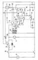
- the single figure of this drawingshows, very schematically, a fuel gas valve control device established in accordance with the invention.
- the valve 1 to be controlledis suitable for distributing a pressurized combustible gas to the burner of a combustible gas appliance such as, in particular, a water heater, a bath heater or a central heating boiler with hot water.
- a combustible gas appliancesuch as, in particular, a water heater, a bath heater or a central heating boiler with hot water.
- This closureis itself subject to the circulation of water in the heating body of the gas appliance, circulation due to the drawing of hot water (in the case of water heaters or bath heaters) or to the in operation of a circulation pump 4 (case of central heating boilers): for this purpose, a vacuum created by this circulation is exploited by a differential valve system to actuate said switch 3.
- valve 1As soon as valve 1 is opened, it distributes a pressurized combustible gas to the appliance burner.
- a flame detector 6is therefore provided to check whether the ignition in question is effective or not and it is only in the case where this ignition is obtained before the expiration of the period T o that means controlled by the output of this detector maintains the electrical supply of the valve 1: time delay means or the like are provided to stop the application of the voltage V on the valve, due to the simple excitation of the contactor 2, at the end of the period T o .
- the inventionaims to ensure the total positive security of such an assembly in the sense that any failure automatically results in the closing of the valve.
- the means controlled by the output of the flame detector 6themselves comprise a second relay contactor 7 which is also suitable for applying a continuous or rectified voltage V 'to the valve 1 suitable for opening this valve, voltage having the same amplitude than the voltage V, but possibly generated in a different way.
- this voltage V 'is that W generated by the network or sector 8 (generally known as an alternating voltage of amplitude 220 volts) and rectified through a unidirectional member 9 such as a diode.
- the voltage Vfor its part, could be generated in a similar manner to the voltage V 'through an appropriate time-delay device.
- this triggeringmust not be caused by simulation of a flame, that is to say by emission of an electrical signal falsely produced by the detector 6 even before the opening of the valve 1.
- the first contact 7 1is connected to the terminals of the sector 8 through a resting contact 2 1 of the contactor 2 and two diodes 15 and 16 in series, both mounted in the opposite direction to the diode 9, the diode 15 being furthermore mounted in parallel on valve 1.
- the second contact 7 2As for the second contact 7 2 , it is connected to the terminals of the sector 8 through also the contact 2 1 at rest and two other diodes 17 and 18 also connected in series and in the opposite direction to the diode 9.
- the second contactor 7When starting the installation, while the first contactor 2 is still at rest, the second contactor 7 must also be, the excitation of the latter being provided only after ignition of the gas distributed by the valve 1 , then detection of this ignition at 6, which supposes that said valve is opened by the excitation of the first contactor 2.
- a repairermust then be called in to restart the installation after locating and eliminating the fault.
- the control which has just been describedcan be carried out immediately after closing of the general switch 19 or after closing of the switch 3, but before tripping of the first contactor 2, a small delay t o , for example of the order of the second, being advantageously provided for this purpose between these last two commands.
- a diode 20, mounted in parallel on the capacitor 10, in the same direction as the diode 15,makes it possible to detect, by breaking the fuse 14, an undesirable "sticking" of the contact 2 2 of the contactor 2 in its working position through the succession of the following components: diode 11, contact 7 1 at work, diode 16 and contact 2 1 at rest.
- valve 1has been closed at the end of the period T o which is shorter than the period T, and begins at the same time as the latter, but the installation remains energized: it must then be disconnected and trigger an alert to make external intervention necessary to repair the fault (which may be due to a phenomenon other than an ignition fault, for example a lack of gas).
- a circuit breaker 21is provided for this purpose, in particular of the thermal or timed type, having the same role as the fuse 14 above and the sensitive element of which (at temperature or time) is supplied as soon as the first contactor 2 is tripped. from sector 8 through contact 2 1 at work, a diode 22 and contact 7 2 at rest.
- the coil of contactor 2is electrically energized, under the control of switch 3, from the secondary of a transformer 23 whose primary is supplied by sector 8.
- This supplyis carried out through an opto-electronic barrier member shown diagrammatically in the drawing by a photothyristor 24, the door of which is connected to a resistor 25.
- This barriercan only be removed if the photosensitive element 24 is illuminated from a lamp 26, such as a photoluminescent diode, which lamp can only be supplied electrically, from the sector, only through the element. sensitive of the circuit breaker 21, as well as through the diode 22 and the contact 7 2 at rest.
- a lamp 26such as a photoluminescent diode, which lamp can only be supplied electrically, from the sector, only through the element. sensitive of the circuit breaker 21, as well as through the diode 22 and the contact 7 2 at rest.
- This optical coupling between the lamp 26 and the photosensitive element 24, shown diagrammatically by the broken arrow 0makes it possible to selectively and surely transmit an instruction from a medium voltage circuit (220 Volts) to a low voltage circuit (for example 24 Volts), without causing any disturbance to these circuits.
- the first contactor 2can only be energized if the circuit breaker 21 and its supply circuit are intact and ready to fulfill their protection mission, which constitutes a new important advantage of the invention.
- the inventionis in no way limited to those of its modes of application and embodiments which have been more especially envisaged; on the contrary, it embraces all the variants, in particular those where the photosensitive element 24 is not a photothyristor, but a phototransistor, a resistance then being provided between the two pads intended to interact alternately with the movable contact 7 2 according to the position of the latter.
Landscapes
- Engineering & Computer Science (AREA)
- Chemical & Material Sciences (AREA)
- Combustion & Propulsion (AREA)
- Mechanical Engineering (AREA)
- General Engineering & Computer Science (AREA)
- Regulation And Control Of Combustion (AREA)
- Pipeline Systems (AREA)
- Control Of Combustion (AREA)
- Feeding And Controlling Fuel (AREA)
- Driving Mechanisms And Operating Circuits Of Arc-Extinguishing High-Tension Switches (AREA)
Abstract
Description
Translated fromFrenchL'invention est relative aux dispositifs pour la commande contrôlée de l'ouverture et de la fermeture d'une vanne de distribution d'un gaz combustible sous pression alimentant notamment un brûleur de chauffe-eau, chauffe-bains ou chaudière de chauffage central à eau chaude, commande devant se traduire automatiquement par la fermeture de ladite vanne après un retard prédéterminé To consécutif à son ouverture si le gaz sous pression délivré par cette vanne n'a pas été allumé entre-temps.The invention relates to devices for the controlled control of the opening and closing of a valve for distributing a pressurized combustible gas supplying in particular a burner for a water heater, bath heater or central heating boiler with hot water, control to automatically result in the closing of said valve after a predetermined delay To consecutive to its opening if the pressurized gas delivered by this valve has not been ignited in the meantime.
Elle vise plus particulièrement, parmi ces dispositifs, ceux dont la commande est assurée par la fermeture d'un interrupteur électrique de commande et met en jeu successivement l'excitation d'un premier contacteur à relais destiné à assurer l'ouverture de la vanne en alimentant celle-ci à l'aide d'une tension électrique redressée ou continue, l'actionnement d'un allumeur dudit gaz, la détection de la flamme correspondant au gaz ainsi allumé, la fermeture automatique de ladite vanne si cette détection n'est pas effective à la fin du retard To et dans le cas contraire, l'excitation d'un second contacteur à relais à plusieurs contacts mobiles monté de façon à arrêter le fonctionnement de l'allumeur et à maintenir l'alimentation électrique de la vanne, au-delà de la période To, par une tension alternative redressée.Among these devices, it relates more particularly to those whose control is ensured by the closing of an electrical control switch and successively involves the excitation of a first relay contactor intended to ensure the opening of the valve by supplying the latter with a rectified or continuous electric voltage, actuation of an igniter of said gas, detection of the flame corresponding to the gas thus ignited, automatic closing of said valve if this detection is not not effective at the end of the delay To and in the opposite case, the excitation of a second relay contactor with several movable contacts mounted so as to stop the operation of the igniter and to maintain the electrical supply to the valve , beyond the period To , by a rectified AC voltage.
Dans le brevet FR-A-2 284 091, on a décrit un tel dispositif de commande de vanne dans lequel un élément disjoncteur de protection est monté de façon à sauter et à couper alors la susdite alimentation de maintien lorsque le dispositif présente certaines défaillances, et en particulier lorsque l'un des contacts mobiles du second contacteur à relais est en mauvaise position lors du démarrage.In patent FR-A-2 284 091, such a valve control device has been described in which a protective circuit breaker element is mounted so as to jump and then cut off the said holding power supply when the device exhibits certain failures, and in particular when one of the movable contacts of the second relay contactor is in the wrong position during startup.
L'invention a pour but, surtout, d'accroître encore la sécurité de ces dispositifs de commande de vanne, en ce sens que toute défaillance d'un tel dispositif se traduit automatiquement par la fermeture de la vanne correspondante: une telle défaillance est en particulier le "collage" indésirable de n'importe lequel des contacts mobiles du second contacteur en sa position pour laquelle ce contacteur commande l'alimentation de la vanne, ou encore la rupture du circuit d'alimentation d'un disjoncteur de protection.The invention aims, above all, to further increase the safety of these valve control devices, in the sense that any failure of such a device automatically results in the closing of the corresponding valve: such a failure is in in particular the undesirable "sticking" of any of the movable contacts of the second contactor in its position for which this contactor controls the supply of the valve, or even the rupture of the supply circuit of a protective circuit breaker.
A cet effet, les dispositifs de commande du genre en question selon l'invention sont essentiellement caractérisés en ce que, pour faire sauter automatiquement l'élément disjoncteur lorsque l'un quelconque des contacts mobiles du second contacteur à relais se trouve en sa position de travail alors que le premier contacteur est au repos, chacun desdits contacts mobiles, en position de travail, branche en série la source de tension, l'élément disjoncteur de protection, l'un des contacts fermé du premier contacteur à relais au repos et des moyens redresseurs permettant le passage d'un courant redressé dans le sens opposé à celui assurant normalement l'alimentation de la vanne au-delà de chaque période To. Dans des modes de réalisation préférés, on a recours en outre à l'une et/ou à l'autre des dispositions suivantes:
- - il est prévu un second disjoncteur de protection agencé de façon à être déclenché au bout d'une période T1 consécutive à l'excitation du premier contacteur si le second contacteur n'a pas été excité pendant cette période T,, et le circuit qui assure l'excitation du premier contacteur à partir de la fermeture de l'interrupteur de commande comprend un organe de verrouillage électrique susceptible d'être rendu conducteur exclusivement par l'éclairage provenant d'un élément lumineux alimenté électriquement à travers l'élément sensible du disjoncteur;
- - dans un dispositif de commande selon l'alinéa précédent, l'alimentation électrique du disjoncteur est effectuée à travers un contact au repos du second contacteur,
- - l'alimentation électrique de la vanne due à l'excitation du premier contacteur est effectuée par simple décharge d'un condensateur.
- - There is a second protective circuit breaker arranged to be tripped after a period T1 consecutive to the excitation of the first contactor if the second contactor has not been energized during this period T ,, and the circuit which ensures the excitation of the first contactor from the closing of the control switch comprises an electrical locking member capable of being made conductive exclusively by the lighting coming from a light element electrically supplied through the sensitive element the circuit breaker;
- - in a control device according to the preceding paragraph, the electrical supply of the circuit breaker is carried out through a contact at rest of the second contactor,
- - the electrical supply to the valve due to the excitation of the first contactor is carried out by simple discharge of a capacitor.
L'invention comprend, mises à part ces dispositions principales, certaines autres dispositions qui s'utilisent de préférence en même temps et dont il sera plus explicitement question ci-après.The invention includes, apart from these main provisions, certain other provisions which are preferably used at the same time and which will be more explicitly discussed below.
Dans ce qui suit, l'on va décrire un mode de réalisation préféré de l'invention en se référant au dessin ci-annexé, d'une manière bien entendu non limitative.In what follows, a preferred embodiment of the invention will be described with reference to the accompanying drawing, of course in a non-limiting manner.
La figure unique de ce dessin montre, très schématiquement, un dispositif de commande de vanne à gaz combustible établi conformément à l'invention.The single figure of this drawing shows, very schematically, a fuel gas valve control device established in accordance with the invention.
La vanne 1 à commander est propre à distribuer un gaz combustible sous pression au brûleur d'un appareil à gaz combustible tel que notamment, un chauffe-eau, un chauffe-bains ou une chaudière de chauffage central à eau chaude.The valve 1 to be controlled is suitable for distributing a pressurized combustible gas to the burner of a combustible gas appliance such as, in particular, a water heater, a bath heater or a central heating boiler with hot water.
Il s'agit d'une vanne de sécurité en ce sens qu'elle s'ouvre uniquement lors de l'application sur elle d'une tension continue ou redressée V, toute absence d'alimentation électrique de cette vanne se traduisant par sa fermeture.It is a safety valve in the sense that it only opens when a direct or rectified voltage V is applied to it, any absence of electrical supply from this valve resulting in its closing. .
De façon connue en soi, l'application de cette tension V sur la vanne 1 est assurée par l'excitation d'un contacteur à relais 2, excitation elle-même commandée par la fermeture d'un interrupteur électrique de commande 3.In a manner known per se, the application of this voltage V on the valve 1 is ensured by the excitation of a
Cette fermeture est elle-même asservie à la circulation de l'eau dans le corps de chauffe de l'appareil à gaz, circulation due à un puisage d'eau chaude (cas des chauffe-eau ou chauffe-bains) ou à la mise en marche d'une pompe de circulation 4 (cas des chaudières de chauffage central): à cet effet, une dépression créée par cette circulation est exploitée par un système à valve différentielle pour actionner ledit interrupteur 3.This closure is itself subject to the circulation of water in the heating body of the gas appliance, circulation due to the drawing of hot water (in the case of water heaters or bath heaters) or to the in operation of a circulation pump 4 (case of central heating boilers): for this purpose, a vacuum created by this circulation is exploited by a differential valve system to actuate said
Dès ouverture de la vanne 1, celle-ci distribue au brûleur de l'appareil un gaz combustible sous pression.As soon as valve 1 is opened, it distributes a pressurized combustible gas to the appliance burner.
On synchronise avec le début de cette ouverture l'excitation d'un allumeur 5 propre à allumer le gaz ainsi distribué.The excitation of an
On sait l'importance attachée à l'allumage effectif de ce gaz: en particulier, si cet allumage n'est pas assuré au bout d'une période To (comprise entre 1 et 5 secondes, de préférence de l'ordre de 3 secondes) consécutive à l'ouverture de la vanne, il faut que cette dernière se referme automatiquement.We know the importance attached to the effective ignition of this gas: in particular, if this ignition is not ensured after a period To (between 1 and 5 seconds, preferably of the order of 3 seconds) following the opening of the valve, it must close automatically.
On prévoit donc un détecteur 6 de flamme pour vérifier si l'allumage en question est effectif ou non et c'est seulement dans le cas où cet allumage est obtenu avant l'expiration de la période To que des moyens asservis à la sortie de ce détecteur maintiennent l'alimentation électrique de la vanne 1: des moyens de temporisation ou analogues sont prévus pour faire cesser l'application de la tension V sur la vanne, due à la simple excitation du contacteur 2, à la fin de la période To.A
L'invention a pour but d'assurer la sécurité positive totale d'un tel ensemble en ce sens que toute défaillance se traduise automatiquement par la fermeture de la vanne.The invention aims to ensure the total positive security of such an assembly in the sense that any failure automatically results in the closing of the valve.
Les moyens asservis à la sortie du détecteur de flamme 6 comprennent eux-mêmes un second contacteur à relais 7 propre, lui aussi, à appliquer sur la vanne 1 une tension continue ou redressée V' propre à ouvrir cette vanne, tension présentant la même amplitude que la tension V, mais engendrée éventuellement d'une manière différente.The means controlled by the output of the
Dans le cas présent, cette tension V' est celle W engendrée par le réseau ou secteur 8 (savoir généralement une tension alternative d'amplitude 220 Volts) et redressée à travers un organe unidirectionnel 9 tel qu'une diode.In the present case, this voltage V 'is that W generated by the network or sector 8 (generally known as an alternating voltage of amplitude 220 volts) and rectified through a unidirectional member 9 such as a diode.
(Dans un souci de simplicité, cet organe unidirectionnel et ceux du même genre seront désignés dans la suite par le vocable "diode", mais ce d'une manière non limitative, tous autres organes unidirectionnels ou redresseurs pouvant être également envisagés pour les constituer.)(For the sake of simplicity, this unidirectional member and those of the same kind will be designated hereinafter by the term "diode", but this in a nonlimiting manner, all other unidirectional members or rectifiers may also be envisaged to constitute them. )
La tension V, quant à elle, pourrait être engendrée de manière analogue à la tension V' à travers un organe de temporisation approprié.The voltage V, for its part, could be generated in a similar manner to the voltage V 'through an appropriate time-delay device.
Mais elle est de préférence engendrée ici par décharge d'un condensateur 10 à travers une diode 11, ce condensateur étant lui-même, avant actionnement du contacteur 2 ou plus généralement tant que celui-ci n'est pas excité, chargé à partir du secteur 8 à travers une diode 12 et un résistance de charge 13.However, it is preferably generated here by discharging a
Pour que le système ci-dessus soit sûr, il est nécessaire que le second contacteur à relais 7 soit déclenché uniquement en réponse à une détection réelle de flamme.For the above system to be safe, it is necessary that the second relay contactor 7 be tripped only in response to an actual flame detection.
En particulier, il est nécessaire que ce déclenchement ne soit par provoqué par simulation d'une flamme, c'est-à-dire par émission d'un signal électrique élaboré faussement par le détecteur 6 avant même l'ouverture de la vanne 1.In particular, this triggering must not be caused by simulation of a flame, that is to say by emission of an electrical signal falsely produced by the
Il est nécessaire également que les contacts mobiles de ce contacteur 7 soient bien revenus en leur position de repos après l'actionnement précédent de ce contacteur.It is also necessary that the movable contacts of this contactor 7 have returned to their rest position after the previous actuation of this contactor.
Une sécurité totale vis-à-vis de chacun de ces deux défauts est automatiquement assurée, selon l'invention, en montant en série chacun desdits contacts mobiles, lorsqu'ils se trouvent en leur position active (c'est-à-dire correspondant à l'état excité du contacteur 7) et qu'à la fois le premier contacteur 2 se trouve au repos, avec une source de tension continue ou redressée montée en sens inverse, de façon à provoquer alors un court-circuit faisant sauter un fusible 14 de protection de l'installation.Total security with respect to each of these two faults is automatically ensured, according to the invention, by mounting each of said mobile contacts in series, when they are in their active position (that is to say corresponding in the excited state of the contactor 7) and that both the
Sur la figure, les contacts en question, au nombre de deux, ont été désignés par les références 71 et 72,In the figure, the contacts in question, two in number, have been designated by the references 71 and 72 ,
Le premier contact 71 est relié aux bornes du secteur 8 à travers un contact au repos 21 du contacteur 2 et deux diodes 15 et 16 en série, montées toutes les deux en sens inverse de la diode 9, la diode 15 étant en outre montée en parallèle sur la vanne 1.The first contact 71 is connected to the terminals of the sector 8 through a resting
Quant au second contact 72, il est relié aux bornes du secteur 8 à travers également le contact 21 au repos et deux autres diodes 17 et 18 également montées en série et en sens inverse de la diode 9.As for the second contact 72 , it is connected to the terminals of the sector 8 through also the
Le fonctionnement de cette sécurité est le suivant.The operation of this security is as follows.
Lors du démarrage de l'installation, alors que le premier contacteur 2 est encore au repos, le second contacteur 7 doit l'être également, l'excitation de ce dernier n'étant prévue qu'après allumage du gaz distribué par la vanne 1, puis détection de cet allumage en 6, ce qui suppose que ladite vanne est ouverte par l'excitation du premier contacteur 2.When starting the installation, while the
Si donc l'un des contacts 71 et 72 se trouve alors en sa position de travail, c'est qu'il existe un défaut quelque part, soit que ledit contact soit resté "collé" après un fonctionnement précédent, soit que le détecteur 6 ait élaboré prématurément un signal d'excitation du contacteur 7, analogue à celui dû à la présence d'une flamme: ce défaut est immédiatement sanctionné par la création d'un court-circuit à travers le contact en mauvaise position, court-circuit qui fait sauter le fusible 14.If therefore one of the contacts 71 and 72 is then in its working position, it is because there is a fault somewhere, either that said contact has remained "stuck" after a previous operation, or that the
Il faut alors faire appel à un réparateur pour remettre en marche l'installation après repérage et élimination du défaut.A repairer must then be called in to restart the installation after locating and eliminating the fault.
Le contrôle qui vient d'être décrit peut être réalisé immédiatement après fermeture de l'interrupteur général 19 ou après fermeture de l'interrupteur 3, mais avant déclenchement du premier contacteur 2, un petit retard to, par exemple de l'ordre de la seconde, étant avantageusement prévu à cet effet entre ces deux dernières commandes.The control which has just been described can be carried out immediately after closing of the
Dans le même ordre d'idées, une diode 20, montée en parallèle sur le condensateur 10, dans le même sens que la diode 15, permet de détecter, par rupture du fusible 14, un "collage" indésirable du contact 22 du contacteur 2 en sa position de travail à travers la succession des composants suivants: diode 11, contact 71 au travail, diode 16 et contact 21 au repos.In the same vein, a diode 20, mounted in parallel on the
Les éventuels "collages" indésirables de ce dernier contact 21 en sa position de travail sont contrôlés d'une autre façon qui va être maintenant décrite.Any undesirable "collages" of this
Si au bout d'une période T1, par exemple de l'ordre de 10 secondes, consécutive au déclenchement du premier contacteur 2, le second contacteur 7 n'a pas été déclenché, c'est que la détection de flamme à laquelle est asservi ce dernier déclenchement n'a pas été observée.If after a period T1 , for example of the order of 10 seconds, consecutive to the tripping of the
Dans ce cas, la vanne 1 a été refermée au terme de la période To qui est plus courte que la période T, et commence en même temps que celle-ci, mais l'installation demeure sous tension: il faut alors la débrancher et déclencher une alerte pour rendre nécessaire une intervention extérieure en vue de la réparation de la panne (laquelle peut être due à un autre phénomène qu'un défaut d'allumage, par exemple à un manque de gaz).In this case, the valve 1 has been closed at the end of the period To which is shorter than the period T, and begins at the same time as the latter, but the installation remains energized: it must then be disconnected and trigger an alert to make external intervention necessary to repair the fault (which may be due to a phenomenon other than an ignition fault, for example a lack of gas).
On prévoit à cet effet un disjoncteur 21, notamment du type thermique ou temporisé, ayant le même rôle que le fusible 14 ci-dessus et dont l'élément sensible (à la température ou au temps) est alimenté dès déclenchement du premier contacteur 2 à partir du secteur 8 à travers le contact 21 au travail, une diode 22 et le contact 72 au repos.A
L'intégrité de ce circuit d'alimentation du disjoncteur présente une grande importance.The integrity of this circuit breaker supply circuit is of great importance.
Pour que sa coupure éventuelle interdise le fonctionnement de l'installation, on a recours, suivant une intéressante disposition de l'invention, au stratagème suivant.So that its possible interruption prohibits the operation of the installation, use is made, according to an advantageous arrangement of the invention, of the following stratagem.
La bobine du contacteur 2 est excitée électriquement, sous le contrôle de l'interrupteur 3, à partir du secondaire d'un transformateur 23 dont le primaire est alimenté par le secteur 8.The coil of
Cette alimentation est effectuée à travers un organe de barrage opto-électronique schématisé sur le dessin par un photothyristor 24 dont la porte est connectée à une résistance 25.This supply is carried out through an opto-electronic barrier member shown diagrammatically in the drawing by a
Ce barrage ne peut être supprimé que si l'élément photosensible 24 est éclaire à partir d'une lampe 26, telle qu'une diode photoluminescente, laquelle lampe ne peut être alimentée électriquement, à partir du secteur, qu'à travers l'élément sensible du disjoncteur 21, ainsi qu'à travers la diode 22 et le contact 72 au repos.This barrier can only be removed if the
Ce couplage optique entre la lampe 26 et l'élément photosensible 24, schématisé par la flèche brisée 0, permet de transmettre sélectivement et sûrement une instruction d'un circuit sous moyenne tension (220 Volts) à un circuit sous basse tension (par exemple 24 Volts), et ce sans apporter aucune perturbation à ces circuits.This optical coupling between the
Grâce à cette disposition, le premier contacteur 2 ne peut être excité qui si le disjoncteur 21 et son circuit d'alimentation sont intacts et prêts à assurer leur mission de protection, ce qui constitue un nouvel avantage important de l'invention.Thanks to this arrangement, the
On constate en outre qu'un éventuel "collage" indésirable du contact 21 en sa position de travail se traduit par l'alimentation du disjoncteur 21 de la manière indiquée ci-dessus, ce qui déclenche ce dernier si l'allumage véritable du gaz n'entraîne pas l'excitation du second relais 7 avant la fin d'une période T1 consécutive audit collage. On voit encore sur le dessin:
- une résistance 27 montée en série avec la
lampe 26,- - une
autre résistance 28 montée en série avec l'allumeur 5 et avec unediode 29 montée dans le même sens que la diode 9, la valeur de cetterésistance 28 étant nettement supérieure à celle de la résistance 27 de façon telle que lalampe 26 ne puisse être alimentée suffisamment, pour assurer son rôle de vérification, qu'à travers l'élément sensible dudisjoncteur 21 et non pas à travers larésistance 28, trop élevée, qui est montée en parallèle sur cet élément sensible tant que le contacteur 7 est au repos, - - une résistance variable 30, permettant de régler la durée T1, montée en série avec l'élément sensible du
disjoncteur 21, l'ensemble de cette résistance variable et de cet élément sensible étant monté en parallèle sur la diode 17 ci-dessus, - - un voyant lumineux 31 monté en parallèle sur les
éléments 14 et 21, de façon à signaler la rupture de l'un de ces éléments, - - et un rectangle E symbolisant l'ensemble des circuits électroniques propres, les uns à transformer l'information "détection de flamme" du
détecteur 6 en l'excitation électrique du contacteur 7, et les autres à élaborer, en association avec les deuxcomposants 24 et 25, l'excitation électrique ducontacteur 2 à partir du secondaire dutransformateur 23 alors de la fermeture de l'interrupteur 3.
- - une
- a resistor 27 connected in series with the
lamp 26,- - Another
resistor 28 mounted in series with theigniter 5 and with adiode 29 mounted in the same direction as the diode 9, the value of thisresistor 28 being significantly greater than that of the resistor 27 so that thelamp 26 can only be supplied with sufficient power, to ensure its verification role, only through the sensitive element of thecircuit breaker 21 and not through theresistance 28, which is too high, which is mounted in parallel on this sensitive element as long as the contactor 7 is at rest, - a
variable resistor 30, making it possible to adjust the duration T1 , mounted in series with the sensitive element of thecircuit breaker 21, all of this variable resistance and this sensitive element being mounted in parallel on the diode 17 above, - an
indicator light 31 mounted in parallel on theelements - - And a rectangle E symbolizing all of the own electronic circuits, some transforming the "flame detection" information from the
detector 6 into the electrical excitation of the contactor 7, and the others to be developed, in association with the twocomponents contactor 2 from the secondary of thetransformer 23 then of the closing of theswitch 3.
- - Another
Comme il va de soi, et comme il résulte d'ailleur déjà de ce qui précède, l'invention ne se limite nullement à ceux de ses modes d'application et de réalisation qui ont été plus spécialement envisagés; elle en embrasse, au contraire, toutes les variantes, notamment celles ou l'élément photosensible 24 ne serait par un photothyristor, mais un phototransistor, une résistance étant alors prévue entre les deux plots destinés à coagir alternativement avec le contact mobile 72 selon la position de ce dernier.As it goes without saying, and as it follows from elsewhere already from the foregoing, the invention is in no way limited to those of its modes of application and embodiments which have been more especially envisaged; on the contrary, it embraces all the variants, in particular those where the
Claims (4)
Priority Applications (1)
| Application Number | Priority Date | Filing Date | Title |
|---|---|---|---|
| AT80401137TATE12682T1 (en) | 1979-08-01 | 1980-07-31 | SAFETY CONTROL DEVICES FOR GAS VALVES. |
Applications Claiming Priority (2)
| Application Number | Priority Date | Filing Date | Title |
|---|---|---|---|
| FR7919806AFR2462660A1 (en) | 1979-08-01 | 1979-08-01 | IMPROVEMENTS TO DEVICES TO CONTROL SAFELY GAS VALVES |
| FR7919806 | 1979-08-01 |
Publications (2)
| Publication Number | Publication Date |
|---|---|
| EP0023870A1 EP0023870A1 (en) | 1981-02-11 |
| EP0023870B1true EP0023870B1 (en) | 1985-04-10 |
Family
ID=9228532
Family Applications (1)
| Application Number | Title | Priority Date | Filing Date |
|---|---|---|---|
| EP80401137AExpiredEP0023870B1 (en) | 1979-08-01 | 1980-07-31 | Safety control devices for gas valves |
Country Status (5)
| Country | Link |
|---|---|
| EP (1) | EP0023870B1 (en) |
| JP (1) | JPS5623632A (en) |
| AT (1) | ATE12682T1 (en) |
| DE (1) | DE3070452D1 (en) |
| FR (1) | FR2462660A1 (en) |
Families Citing this family (3)
| Publication number | Priority date | Publication date | Assignee | Title |
|---|---|---|---|---|
| JPS58152579A (en)* | 1982-03-08 | 1983-09-10 | 株式会社マグジヤン | Mah-jongg apparatus |
| JPS60249987A (en)* | 1984-05-23 | 1985-12-10 | 都島興産株式会社 | Mahjongg apparatus |
| CN113883415B (en)* | 2021-09-16 | 2024-02-20 | 杨春顺 | A gas automatic circuit breaker |
Family Cites Families (3)
| Publication number | Priority date | Publication date | Assignee | Title |
|---|---|---|---|---|
| US3270800A (en)* | 1964-12-07 | 1966-09-06 | Honeywell Inc | Burner control apparatus |
| DE2442997C2 (en)* | 1974-09-07 | 1976-09-16 | Danfoss As | CONTROL UNIT FOR IGNITING AND MONITORING A COMBUSTION SYSTEM |
| CH582333A5 (en)* | 1975-03-04 | 1976-11-30 | Landis & Gyr Ag |
- 1979
- 1979-08-01FRFR7919806Apatent/FR2462660A1/enactiveGranted
- 1980
- 1980-07-31JPJP10583180Apatent/JPS5623632A/enactivePending
- 1980-07-31DEDE8080401137Tpatent/DE3070452D1/ennot_activeExpired
- 1980-07-31EPEP80401137Apatent/EP0023870B1/ennot_activeExpired
- 1980-07-31ATAT80401137Tpatent/ATE12682T1/enactive
Also Published As
| Publication number | Publication date |
|---|---|
| EP0023870A1 (en) | 1981-02-11 |
| FR2462660B1 (en) | 1982-09-03 |
| JPS5623632A (en) | 1981-03-06 |
| ATE12682T1 (en) | 1985-04-15 |
| DE3070452D1 (en) | 1985-05-15 |
| FR2462660A1 (en) | 1981-02-13 |
Similar Documents
| Publication | Publication Date | Title |
|---|---|---|
| CH638603A5 (en) | BURNER CONTROL APPARATUS. | |
| FR2462749A1 (en) | FIRE DETECTOR AND FIRE ALARM SYSTEM USING SUCH A DETECTOR | |
| NL7906841A (en) | FUEL IGNITION SYSTEM. | |
| EP0166358B1 (en) | Network junction control device of an electric circuit | |
| FR2979149A1 (en) | THERMAL SURVEILLANCE DEVICE FOR TERMINALS OF AN ELECTRICAL CONNECTION DEVICE | |
| EP0023870B1 (en) | Safety control devices for gas valves | |
| EP0439417B1 (en) | Safety device for the operating of a burner | |
| EP0834975B1 (en) | Electrical distribution terminal with hybrid limiter block | |
| EP0034979B1 (en) | Fuel burner provided with an electric motor | |
| FR2587094A1 (en) | Fail-safe security circuit for gas- or oil-fired burner | |
| FR2485165A1 (en) | CONTROL CIRCUIT FOR A HEATING SYSTEM | |
| JPS6359047B2 (en) | ||
| FR2671168A1 (en) | Gas control apparatus for multiple burners | |
| FR2583856A1 (en) | TEMPORIZED CUTTING CIRCUIT OF A GAS BURNER | |
| FR2493476A2 (en) | Automatic flame detector and ignition controller for gas burner - uses programmable unijunction transistors driving thyristors and relays to provide flame detection and controlled delays before re-ignition | |
| FR2771587A1 (en) | Shunt for failed low-voltage electric lamps connected in series | |
| US2760115A (en) | Mercury vapor lighting system | |
| EP0290314B1 (en) | Operating circuit for electric remote-control apparatuses, especially remotely controlled brakers, and apparatuses incorporating this circuit | |
| BE714221A (en) | ||
| FR2737057A1 (en) | FAULT SIGNALING COMMUNICATION CIRCUIT AND ASSOCIATED TEST MODULE | |
| CH519141A (en) | Heating installation | |
| US3673464A (en) | Energization system with safety provision for faulty rectifier | |
| FR2616888A1 (en) | ULTRAVIOLET RAY FLAME DETECTOR | |
| FR2493964A1 (en) | Catalytic gas combustion temp. controller with catalyst reheating - uses operational amplifier circuit driving relays to position solenoid valves regulating combustion and has preheat control | |
| FR2489932A1 (en) | Flame detector for monitoring burners in installation - uses logic gates operated from currents in flame sensor load resistors to drive relay circuits |
Legal Events
| Date | Code | Title | Description |
|---|---|---|---|
| PUAI | Public reference made under article 153(3) epc to a published international application that has entered the european phase | Free format text:ORIGINAL CODE: 0009012 | |
| AK | Designated contracting states | Designated state(s):AT BE CH DE GB IT NL | |
| 17P | Request for examination filed | Effective date:19810807 | |
| ITF | It: translation for a ep patent filed | ||
| GRAA | (expected) grant | Free format text:ORIGINAL CODE: 0009210 | |
| AK | Designated contracting states | Designated state(s):AT BE CH DE GB IT LI NL | |
| REF | Corresponds to: | Ref document number:12682 Country of ref document:AT Date of ref document:19850415 Kind code of ref document:T | |
| REF | Corresponds to: | Ref document number:3070452 Country of ref document:DE Date of ref document:19850515 | |
| PLBE | No opposition filed within time limit | Free format text:ORIGINAL CODE: 0009261 | |
| STAA | Information on the status of an ep patent application or granted ep patent | Free format text:STATUS: NO OPPOSITION FILED WITHIN TIME LIMIT | |
| 26N | No opposition filed | ||
| PGFP | Annual fee paid to national office [announced via postgrant information from national office to epo] | Ref country code:DE Payment date:19890717 Year of fee payment:10 | |
| ITTA | It: last paid annual fee | ||
| PG25 | Lapsed in a contracting state [announced via postgrant information from national office to epo] | Ref country code:LI Effective date:19890731 Ref country code:CH Effective date:19890731 | |
| PGFP | Annual fee paid to national office [announced via postgrant information from national office to epo] | Ref country code:NL Payment date:19890731 Year of fee payment:10 Ref country code:GB Payment date:19890731 Year of fee payment:10 | |
| PGFP | Annual fee paid to national office [announced via postgrant information from national office to epo] | Ref country code:BE Payment date:19890809 Year of fee payment:10 | |
| PGFP | Annual fee paid to national office [announced via postgrant information from national office to epo] | Ref country code:AT Payment date:19890811 Year of fee payment:10 | |
| REG | Reference to a national code | Ref country code:CH Ref legal event code:PL | |
| PG25 | Lapsed in a contracting state [announced via postgrant information from national office to epo] | Ref country code:GB Effective date:19900731 Ref country code:BE Effective date:19900731 Ref country code:AT Effective date:19900731 | |
| BERE | Be: lapsed | Owner name:CHAFFOTEAUX ET MAURY Effective date:19900731 | |
| PG25 | Lapsed in a contracting state [announced via postgrant information from national office to epo] | Ref country code:NL Effective date:19910201 | |
| NLV4 | Nl: lapsed or anulled due to non-payment of the annual fee | ||
| GBPC | Gb: european patent ceased through non-payment of renewal fee | ||
| PG25 | Lapsed in a contracting state [announced via postgrant information from national office to epo] | Ref country code:DE Effective date:19910403 |