EP0016343B1 - Continuous-infusion device - Google Patents
Continuous-infusion deviceDownload PDFInfo
- Publication number
- EP0016343B1 EP0016343B1EP80100810AEP80100810AEP0016343B1EP 0016343 B1EP0016343 B1EP 0016343B1EP 80100810 AEP80100810 AEP 80100810AEP 80100810 AEP80100810 AEP 80100810AEP 0016343 B1EP0016343 B1EP 0016343B1
- Authority
- EP
- European Patent Office
- Prior art keywords
- syringe
- clockwork
- spring
- cover
- wings
- Prior art date
- Legal status (The legal status is an assumption and is not a legal conclusion. Google has not performed a legal analysis and makes no representation as to the accuracy of the status listed.)
- Expired
Links
- 238000001802infusionMethods0.000titleclaimsabstractdescription14
- 230000007246mechanismEffects0.000claimsdescription34
- 238000002347injectionMethods0.000claimsdescription18
- 239000007924injectionSubstances0.000claimsdescription18
- 230000005540biological transmissionEffects0.000claimsdescription6
- 238000004804windingMethods0.000claimsdescription5
- 230000004907fluxEffects0.000claims1
- 210000001331noseAnatomy0.000claims1
- 239000007788liquidSubstances0.000abstractdescription2
- 230000001105regulatory effectEffects0.000abstract1
- 230000033001locomotionEffects0.000description12
- 230000002401inhibitory effectEffects0.000description3
- 206010038743RestlessnessDiseases0.000description2
- 239000003795chemical substances by applicationSubstances0.000description2
- 230000006378damageEffects0.000description2
- 238000000034methodMethods0.000description2
- 241001631457CannulaSpecies0.000description1
- 208000032953Device battery issueDiseases0.000description1
- 208000001431Psychomotor AgitationDiseases0.000description1
- 230000006978adaptationEffects0.000description1
- 239000008280bloodSubstances0.000description1
- 210000004369bloodAnatomy0.000description1
- 238000010276constructionMethods0.000description1
- 201000010099diseaseDiseases0.000description1
- 208000037265diseases, disorders, signs and symptomsDiseases0.000description1
- 239000003814drugSubstances0.000description1
- 229940079593drugDrugs0.000description1
- 230000000694effectsEffects0.000description1
- 230000005611electricityEffects0.000description1
- 230000001771impaired effectEffects0.000description1
- 239000003112inhibitorSubstances0.000description1
- 229940126601medicinal productDrugs0.000description1
- 230000002028prematureEffects0.000description1
- 239000000126substanceSubstances0.000description1
Images


Classifications
- A—HUMAN NECESSITIES
- A61—MEDICAL OR VETERINARY SCIENCE; HYGIENE
- A61M—DEVICES FOR INTRODUCING MEDIA INTO, OR ONTO, THE BODY; DEVICES FOR TRANSDUCING BODY MEDIA OR FOR TAKING MEDIA FROM THE BODY; DEVICES FOR PRODUCING OR ENDING SLEEP OR STUPOR
- A61M5/00—Devices for bringing media into the body in a subcutaneous, intra-vascular or intramuscular way; Accessories therefor, e.g. filling or cleaning devices, arm-rests
- A61M5/14—Infusion devices, e.g. infusing by gravity; Blood infusion; Accessories therefor
- A61M5/142—Pressure infusion, e.g. using pumps
- A61M5/145—Pressure infusion, e.g. using pumps using pressurised reservoirs, e.g. pressurised by means of pistons
- A61M5/1452—Pressure infusion, e.g. using pumps using pressurised reservoirs, e.g. pressurised by means of pistons pressurised by means of pistons
- A61M5/1454—Pressure infusion, e.g. using pumps using pressurised reservoirs, e.g. pressurised by means of pistons pressurised by means of pistons spring-actuated, e.g. by a clockwork
- A—HUMAN NECESSITIES
- A61—MEDICAL OR VETERINARY SCIENCE; HYGIENE
- A61M—DEVICES FOR INTRODUCING MEDIA INTO, OR ONTO, THE BODY; DEVICES FOR TRANSDUCING BODY MEDIA OR FOR TAKING MEDIA FROM THE BODY; DEVICES FOR PRODUCING OR ENDING SLEEP OR STUPOR
- A61M5/00—Devices for bringing media into the body in a subcutaneous, intra-vascular or intramuscular way; Accessories therefor, e.g. filling or cleaning devices, arm-rests
- A61M5/14—Infusion devices, e.g. infusing by gravity; Blood infusion; Accessories therefor
- A61M5/142—Pressure infusion, e.g. using pumps
- A61M5/145—Pressure infusion, e.g. using pumps using pressurised reservoirs, e.g. pressurised by means of pistons
- A61M2005/14506—Pressure infusion, e.g. using pumps using pressurised reservoirs, e.g. pressurised by means of pistons mechanically driven, e.g. spring or clockwork
- A—HUMAN NECESSITIES
- A61—MEDICAL OR VETERINARY SCIENCE; HYGIENE
- A61M—DEVICES FOR INTRODUCING MEDIA INTO, OR ONTO, THE BODY; DEVICES FOR TRANSDUCING BODY MEDIA OR FOR TAKING MEDIA FROM THE BODY; DEVICES FOR PRODUCING OR ENDING SLEEP OR STUPOR
- A61M5/00—Devices for bringing media into the body in a subcutaneous, intra-vascular or intramuscular way; Accessories therefor, e.g. filling or cleaning devices, arm-rests
- A61M5/14—Infusion devices, e.g. infusing by gravity; Blood infusion; Accessories therefor
- A61M5/142—Pressure infusion, e.g. using pumps
- A61M5/145—Pressure infusion, e.g. using pumps using pressurised reservoirs, e.g. pressurised by means of pistons
- A61M5/1452—Pressure infusion, e.g. using pumps using pressurised reservoirs, e.g. pressurised by means of pistons pressurised by means of pistons
- A61M5/1456—Pressure infusion, e.g. using pumps using pressurised reservoirs, e.g. pressurised by means of pistons pressurised by means of pistons with a replaceable reservoir comprising a piston rod to be moved into the reservoir, e.g. the piston rod is part of the removable reservoir
- Y—GENERAL TAGGING OF NEW TECHNOLOGICAL DEVELOPMENTS; GENERAL TAGGING OF CROSS-SECTIONAL TECHNOLOGIES SPANNING OVER SEVERAL SECTIONS OF THE IPC; TECHNICAL SUBJECTS COVERED BY FORMER USPC CROSS-REFERENCE ART COLLECTIONS [XRACs] AND DIGESTS
- Y10—TECHNICAL SUBJECTS COVERED BY FORMER USPC
- Y10S—TECHNICAL SUBJECTS COVERED BY FORMER USPC CROSS-REFERENCE ART COLLECTIONS [XRACs] AND DIGESTS
- Y10S128/00—Surgery
- Y10S128/12—Pressure infusion
Definitions
- the inventionrelates to a device for continuous infusions, the drive for driving an injection syringe has a spring mechanism for advancing the syringe plunger and a mechanical clockwork for controlling the plunger feed.
- the deviceis equipped with an actuation mechanism which comprises a clockwork which drives a slide along a spindle, the slide having a toothed lower edge can engage with a gear wheel of the clockwork and is provided with a pin which engages with the spritzlstossel and moves it.
- an actuation mechanismwhich comprises a clockwork which drives a slide along a spindle, the slide having a toothed lower edge can engage with a gear wheel of the clockwork and is provided with a pin which engages with the spritzlstossel and moves it.
- the slide and the gear wheel of the movementare disengaged so that the slide can be moved freely.
- the movementis then coupled to the slide.
- the clockworkthen slowly pushes the plunger into the syringe, pushing the medication out of the syringe.
- the syringe plungeris also driven by the mainspring of the clockwork, so that there is only a single energy accumulator and therefore only a single power flow. If the slide and gear wheel of the clockwork are out of engagement, the full force of the barrel rests on the clockwork - since the unrest is mechanically stopped - and can damage it.
- changes in the loadi.e.
- the other mechanically operating device for continuous infusions(US-A-3 886 938), on the other hand, has two energy stores in the form of two coil springs on the one hand and a main spring on the other, but the power flows of the two energy stores are not separated.
- the spring forceis transferred to the syringe plunger via a base and a toothed rack that can be moved in the device housing, so that it moves in the feed direction.
- the clockwork equipped with the main springshould control the feed speed of the rack via a pinion.
- These two spring meansare in permanent non-positive connection via the pinion, so that there is a constant mutual influence. This has the effect that one of the two spring means is superfluous because the two only generate a single force flow.
- the permanent connection of the two spring meanshas a reaction from the two coil springs to the clockwork mechanism, which is why the main spring also drives the rack and the coil springs also the clockwork and can be easily replaced by a single spring means.
- this deviceis reduced to the state of the device according to DE-A-2 112654, the one force flow of which causes the internal frictional forces of the respective injection syringe to control the push Adulterate the feed rate through the clockwork so that a constant ram feed rate is not achieved.
- the inventionhas for its object to improve a device for continuous infusions according to US-A-3 886 938 so that the syringe plunger is pushed out absolutely evenly, regardless of the frictional forces in the syringe, so that with each type of syringe, the Injection means and the cannula or the line a precisely controlled plunger feed is achieved.
- the spring mechanism and the clockworkare each equipped with a spiral tension spring and gear train ratio and that the two spiral tension springs are mounted coaxially on a spring shaft and connected to a common winding shaft. Both spiral tension springs are always wound up at the same time and a cover for the syringe support, which can be pivoted on a housing having a support for the injection syringe, is used as the lifting means.
- the pivoting coveris connected to the elevator shaft in a rotationally fixed manner. Since the cover covers the syringe support in the housing, it is necessary for the access to the syringe support to pivot the cover and the two spiral tension springs are pulled open.
- a protection against premature closing of the coveris provided.
- Thisconsists of a helical toothed washer which is firmly connected to the cover and which interacts with a spring catch in such a way that the cover can only be closed after it has been pivoted through 180 °. So the cover can only be closed when the propulsion mechanism and the clockwork are fully wound, i.e. the spiral tension springs have been fully tensioned to 180 °.
- a cam surface actuated by a driver pin on the helical toothed diskserves to disengage the spring pawl in the end pivoting position of the cover. It is possible to open the cover to remove the syringe at any time before the total infusion time has expired. The syringe can be removed from the syringe support of the housing as required.
- the spring mechanismdrives a pinion via a transmission, which drives a toothed rack that has an arm that engages the plunger of the syringe and that an eccentric is arranged on the shaft of the second wheel of the clockwork, which opens one operates the armature shaft seated armature, which acts on a switching wheel driven by the spring mechanism, which controls the pinion via the transmission.
- the inhibitorlocks the last drive stage of the feed mechanism and the switching wheel controls the feed of the plunger of the injection syringe, which is caused solely by this, by transmitting holding pulses to the spring mechanism.
- the switching wheelis advantageously designed as an impeller with symmetrically arranged vanes. It is expedient that the ratchet wheel has four wings with a 90 ° spacing, and that the escapement armature is provided with two stop lugs for the ratchet wheel wings. To set different feed speeds of the syringe plunger, it is provided that the width of the vanes is different from one another and that the locking armature for detecting vanes of different widths is arranged on the armature shaft in an axially adjustable manner. The clockwork remains unaffected by this control and always runs with the same runtime.
- the inhibiting armatureis adjusted relative to the switching wheel in such a way that it inhibits as many wings of the switching wheel as possible per unit of time, so that the advancing movement of the syringe plunger is divided into short steps, which increases the overall feed time. Accordingly, in order to shorten the total feed time, the stride length is increased by the inhibiting armature engaging with a smaller number of wings of the switching wheel per unit of time in order to stop the switching wheel less frequently per unit of time.
- a corrugated cam discwhich engages in a transverse slot on the armature shaft, is advantageously used for the axial adjustment of the escapement armature.
- the position of the camcan be adjusted by means of an actuating part on the outer surface of the housing and secured by a locking device. The user can choose the infusion time himself without difficulty, it being possible to switch over during the process.
- a further advantageous embodiment of the inventionis that the rack is guided between a pair of rods which is attached to a rocker arm, one end of which is pivotally connected to the housing and the other end under the action of a tension spring and one connected to the elevator shaft in a rotationally fixed manner Cam disc stands.
- the toothed rackcan be moved freely and the drive is ineffective, so that the syringe can be removed from the housing and fully drawn up or vented again or operated manually to reach another position with the housing open.
- the clockworkcan run without the syringe being actuated because the feed is disengaged.
- a total of three functionsare coupled to the movement of the housing cover, namely the winding of the two spiral tension springs, the protection against closing the cover before the two walking mechanisms are fully lifted, and the disengagement of the feed mechanism when the cover is open.
- the device for continuous infusionsconsists of a housing 1 which has a support 2 which is open to the side for an injection syringe 3, e.g. B. has a single-use syringe.
- An arm 4 of a rackwhich can be coupled within the housing with a feed drive projects into the syringe support 2.
- the arm 4presses against a plunger 3A of the injection syringe 3.
- a cover 5is used to close the syringe support 2.
- This coveris designed as an angle plate and is pivotably mounted on the housing at 6.
- the fulcrum of the cover 5is arranged on the housing such that the front end of the injection syringe 3 is always released first when the cover 5 is pivoted to open in the direction of arrow A. Finger recesses 7 facilitate the handling of the device.
- the deviceis characterized in that a separate power flow is provided for the clockwork and for the feed mechanism.
- the mechanism of the clockworkis arranged on one side of the longitudinal center plane of the housing, while the mechanism of the feed mechanism is on the other side of the longitudinal center plane of the housing (FIG. 3).
- the spiral tension spring 3is located on the underside of the housing. It consists in the usual way of a spiral tension spring 8, the force of which is transmitted to a gear 12 via a gear 18, a minute wheel 9, a small bottom wheel 10 and a second wheel 11.
- the spiral tension spring 8is connected via a toothed wheel 14 and a toothed disk 15 to an elevator shaft 13.
- the elevator shaft 13is connected in a rotationally fixed manner at 6 to the cover 5 of the housing, so that the spiral tension spring 8 is pulled up when the cover 5 is pivoted.
- the elevator shaft 13also acts on a spiral tension spring 16 associated with the feed mechanism, which is arranged coaxially to the spiral tension spring 8 on a shaft 17. In this way, both spiral tension springs 8 and 16 are pulled evenly when the cover 5 is pivoted. In order to ensure that the cover is always pivoted through 180 °, so that both the clockwork and the feed mechanism are always fully tensioned, the disk arrangement illustrated in FIGS. 6-8 is provided.
- a partially helically toothed disk 19is firmly connected to the cover 5, so that it moves when the cover 5 is pivoted.
- This helical toothed disk 19carries a transverse pin 20 which projects through an arch slot 21 in a second disk 22 which can only be rotated by a small angle piece and has a circumferential recess 23.
- a third partially toothed disk 24is provided coaxially with these two disks 19 and 22.
- an arc slot 25is formed, which is somewhat longer than the arc slot 21 of the disk 22 and through which the pin 20 also projects.
- the force of the spiral tension spring 16 of the feed mechanismis transmitted via a toothed wheel 31 and a gearing 32, which is only indicated in the drawing, to a pinion 33 which interacts with a rack 34, the arm 4 of which engages against the plunger 3A of the injection syringe 3.
- a cam disk 35which is connected to the cover 5 in a rotationally fixed manner, acts via a spring clip 36 or the like on a rocker arm 37, which serves as a carrier for the rack 34.
- One end of the rocker arm 37is pivotally connected to the housing 1 at 38 (Fig.
- the engaged feed mechanismis controlled by the clockwork.
- the control mechanismhas an eccentric 411 on the shaft 42 of the second wheel 11. With the eccentric 411 a fork 43 of an escapement 44 engages, which is pivotably mounted on an armature shaft 45 and has two stop lugs 46 on its lower arm.
- the stop lugs 46 of the locking armature 44interact with the wings of a ratchet wheel 50 (FIG. 4), which is connected via a gearwheel 60 and a transmission to the pinion 33, which transmits the feed to the rack 34.
- the escapement 44 on its shaft 45is axially adjustable.
- a corrugated cam plate 47is used, which can be rotated by hand from the outside by means of an actuating part 48 (FIG. 1) and, by engaging in a transverse slot 49 in the armature shaft 45, causes an axial adjustment of the locking armature 44 so that it has different widths Wings of the switching wheel 50 can engage.
- the switching wheel 50In the example selected, four wings, each offset by 90 ° to one another, are provided on the switching wheel 50. These wings have different widths, namely the wing 51 is half as wide as the wing 52 opposite it, while the other two wings 53 are again half as narrow as the wing 51. If the escapement 44 is set so that it inhibits all four wings 51-53 of the switching wheel 50 when the second wheel 11 rotates, the gear stage on which the switching wheel 50 is seated is blocked four times per minute, which means that there are small thrusts of feed , and the full syringe path is reached in 24 hours.
- the wing arrangement of the switching wheel 50can be chosen differently than in the example shown.
Landscapes
- Health & Medical Sciences (AREA)
- Vascular Medicine (AREA)
- Engineering & Computer Science (AREA)
- Anesthesiology (AREA)
- Biomedical Technology (AREA)
- Heart & Thoracic Surgery (AREA)
- Hematology (AREA)
- Life Sciences & Earth Sciences (AREA)
- Animal Behavior & Ethology (AREA)
- General Health & Medical Sciences (AREA)
- Public Health (AREA)
- Veterinary Medicine (AREA)
- Infusion, Injection, And Reservoir Apparatuses (AREA)
- Massaging Devices (AREA)
Abstract
Description
Translated fromGermanDie Erfindung bezieht sich auf ein Gerät für Dauerinfusionen, dessen Laufwerk zum Antrieb einer Injektionsspritze einen Federmechanismus zum Vorschub des Spritzenstössels und ein mechanisches Uhrwerk zur Steuerung des Stösselvorschubes aufweist.The invention relates to a device for continuous infusions, the drive for driving an injection syringe has a spring mechanism for advancing the syringe plunger and a mechanical clockwork for controlling the plunger feed.
Zur Behandlung vieler Krankheiten ist es erforderlich, kleine Dosen hochwirksamer körpereigener chemischer Substanzen und Arzneimittel über einen längeren Zeitraum kontinuierlich in die Blutbahn eines Patienten abzugeben. Es ist bekannt, für derartige Dauerinjektionen Laufwerke zum Antrieb von Injektionsspritzen zu verwenden, die in kleinen Gehäusen untergebracht sind, die am Patienten befestigt werden können. Bekannte Laufwerke arbeiten mit einem Elektromotor mit Batterieantrieb. Ober ein Getriebe wird eine Mutter auf einem Gewinde in Drehbewegung versetzt, und es wird die lineare Bewegung der Mutter auf den Kolben einer Injektionsspritze übertragen. Ein Uhrwerk fehlt bei dieser bekannten Konstruktion. Die Vorschubsteuerung ergibt sich durch die Art des Getriebes, und für verschiedene Infusionszeiten werden jeweils gesonderte Geräteausführungen benötigt. Zur Einstellung der Dosisrate ist jeweils eine besondere Anpassung der Fliessfähigkeit des zu injizierenden Mittels erforderlich. Eine gewisse Unzuverlässigkeit ergibt sich bei diesem Gerät durch die Abhängigkeit von dem Ladungszustand der Batterie. Bei unvorhergesehenem Batterleausfall wird die Injektion sofort unterbrochen. Der Anschluss eines solchen Gerätes an ein Stromnetz kann zwar diese Unsicherheit beheben, jedoch ist der Patient in diesem Falle für die Dauer der Injektion stadortgebunden. Im übrigen hat sich gezeigt, dass jede Einleitung von Elektrizität in den lebendigen Körper selbst in der Grössenordnung von Mikroampere Herzbeschwerden verursacht.To treat many diseases, it is necessary to continuously release small doses of highly effective chemical substances and medicinal products into the patient's blood stream over a longer period of time. It is known to use drives for driving syringes, which are housed in small housings that can be attached to the patient, for such continuous injections. Known drives work with an electric motor with battery drive. A nut is rotated on a thread via a gear, and the linear motion of the nut is transmitted to the plunger of an injection syringe. A clockwork is missing in this known construction. The feed control is determined by the type of gear and separate device versions are required for different infusion times. To adjust the dose rate, a special adjustment of the fluidity of the agent to be injected is required. A certain unreliability arises with this device due to the dependency on the state of charge of the battery. In the event of an unforeseen battery failure, the injection is interrupted immediately. The connection of such a device to a power network can eliminate this uncertainty, but in this case the patient is bound to the location for the duration of the injection. In addition, it has been shown that any introduction of electricity into the living body, even on the order of microamps, causes heart problems.
Um die mit einem elektrischen Antrieb verbundenen Nachteile zu vermeiden, sind mechanische Laufwerke zum Antrieb von Injektionsspritzen für Dauerinfusionen entwickelt worden, bei denen zum Vorschub des Spritzenstössels ein Federmechanismus dient und der Vorschub von einem mechanischen Uhrwerk gesteuert wird (DE-A-2 112 654 und US-A-3 886 938).In order to avoid the disadvantages associated with an electric drive, mechanical drives for driving injection syringes for continuous infusions have been developed, in which a spring mechanism is used to advance the syringe plunger and the advance is controlled by a mechanical clockwork (DE-A-2 112 654 and US-A-3 886 938).
Das Gerät nach der erstgenannten Druckschrift ist mit einem Betätigungsmechanismus ausgestattet, der ein Uhrwerk umfasst, welches einen Schieber längs einer Spindel antreibt, wobei der Schieber mit einer gezahnten unteren Kante mit einem Getrieberad des Uhrwerkes in Eingriff stehen kann und mit einem Stift versehen ist, der mit dem Spritzerlstossel zusammengreift und ihn verschiebt.The device according to the first-mentioned document is equipped with an actuation mechanism which comprises a clockwork which drives a slide along a spindle, the slide having a toothed lower edge can engage with a gear wheel of the clockwork and is provided with a pin which engages with the spritzlstossel and moves it.
Zum Einlegen der gefüllten Spritze und zum Aufziehen des Uhrwerkes werden der Schieber und das Getrieberad des Uhrwerkes ausser Eingriff gebracht, so dass der Schieber frei verschoben werden kann. Sodann wird das Uhrwerk mit dem Schieber gekoppelt. Danach drückt das Uhrwerk den Kolben langsam in die Spritze ein, wodurch das Medikament aus der Spritze gedrückt wird. In diesem Falle wird auch der Spritzenstössel von der Triebfeder des Uhrwerkes angetrieben, so dass nur ein einziger Kraftspeicher und damit auch nur einziger Kraftfluss vorhanden ist. Wenn Schieber und Getrieberad des Uhrwerkes sich ausser Eingriff befinden, lastet - da die Unruhe mechanisch gestoppt wird - die volle Kraft des Federhauses auf dem Uhrwerk und kann dieses beschädigen. Ausserdem wirken sich Änderungen der Last, d.h. der durch die Viskosität des zu injizierenden Mittels und den Kanalquerschnitt von Leitungen und Kanülen sowie innere Reibkräfte der Spritze bedingten Kräfte zur Betätigung der Spritze, voll als Variation der für das Uhrwerk verbleibenden Antriebskraft aus. Dies hat zur Folge, dass bei schwergängigen Spritzen und/oder hohem Flüssigkeitsgegendruck (hohe Viskosität, enge Leitung und Kanüle) die Kraft zu null werden kann, die das Uhrwerk und den Spritzenstössel antreiben soll; das Gerät bleibt stehen und erfüllt seinen medizinischen Zweck nicht. Ist die Spritze leichtgängig, so verbleibt für das Uhrwerk so viel Antriebskraft, dass der Anker bzw. die Unruhe durch Prellschwingungen stark gefährdet sind. Das kann zur plötzlichen Zerstörung führen, setzt aber zumindest die Lebensdauer des Gerätes beträchtlich herab, wie die Praxis gezeigt hat. Ferner wird die Genauigkeit der Zeitsteuerung beeinträchtigt.To insert the filled syringe and to wind up the movement, the slide and the gear wheel of the movement are disengaged so that the slide can be moved freely. The movement is then coupled to the slide. The clockwork then slowly pushes the plunger into the syringe, pushing the medication out of the syringe. In this case, the syringe plunger is also driven by the mainspring of the clockwork, so that there is only a single energy accumulator and therefore only a single power flow. If the slide and gear wheel of the clockwork are out of engagement, the full force of the barrel rests on the clockwork - since the unrest is mechanically stopped - and can damage it. In addition, changes in the load, i.e. the forces caused by the viscosity of the agent to be injected and the channel cross-section of lines and cannulas as well as the internal frictional forces of the syringe to actuate the syringe, as a variation of the driving force remaining for the clockwork. The consequence of this is that with stiff syringes and / or high liquid back pressure (high viscosity, narrow line and cannula) the force which should drive the clockwork and the syringe plunger can become zero; the device stops and does not fulfill its medical purpose. If the syringe runs smoothly, there is so much driving force for the clockwork that the anchor or the restlessness are strongly endangered by bouncing vibrations. This can lead to sudden destruction, but at least considerably reduces the lifespan of the device, as practice has shown. Furthermore, the accuracy of the timing is impaired.
Das andere mechanisch arbeitende Gerät für Dauerinfusionen (US-A-3 886 938) weist demgegenüber zwar zwei Kraftspeicher in Form von zwei Schraubenfedern einerseits und einer Hauptfeder anderseits auf, jedoch sind die Kraftflüsse der beiden Kraftspeicher nicht getrennt. Die Federkraft wird über eine in dem Gerätegehäuse verschiebbar angeordnete Basis und eine Zahnstange auf den Spritzenstössel übertragen, damit er sich in Vorschubrichtung bewegt. Dabei soll das mit der Hauptfeder ausgestattete Uhrwerk über ein Ritzel die Vorschubgeschwindigkeit der Zahnstange steuern. Diese beiden Federmittel stehen über das Ritzel in dauernder kraftschlüssiger Verbindung, so dass eine dauernde gegenseitige Beeinflussung stattfindet. Dies wirkt sich so aus, dass eines der beiden Federmittel überflüssig ist, weil beide nur einen einzigen gemeinsamen Kraftfluss erzeugen. Die dauernde Verbindung der beiden Federmittel hat eine Rückwirkung von den beiden Schraubenfedern auf den Uhrwerkmechanismus zur Folge, weshalb die Hauptfeder auch die Zahnstange und die Schraubenfedern auch das Uhrwerk antreiben und ohne weiteres durch ein einziges Federmittel ersetzt werden können. Trotz des Vorhandenseins von zwei Federmitteln (Kraftspeichern) reduziert sich somit dieses Gerät auf den Stand des Gerätes nach DE-A-2 112654, dessen einer einziger Kraftfluss bewirkt, dass die inneren Reibkräfte der jeweiligen Injektionsspritze die Steuerung des Stösselvorschubes durch das Uhrwerk verfälschen, so dass ein gleichmässiger Stösselvorschub nicht erreicht wird.The other mechanically operating device for continuous infusions (US-A-3 886 938), on the other hand, has two energy stores in the form of two coil springs on the one hand and a main spring on the other, but the power flows of the two energy stores are not separated. The spring force is transferred to the syringe plunger via a base and a toothed rack that can be moved in the device housing, so that it moves in the feed direction. The clockwork equipped with the main spring should control the feed speed of the rack via a pinion. These two spring means are in permanent non-positive connection via the pinion, so that there is a constant mutual influence. This has the effect that one of the two spring means is superfluous because the two only generate a single force flow. The permanent connection of the two spring means has a reaction from the two coil springs to the clockwork mechanism, which is why the main spring also drives the rack and the coil springs also the clockwork and can be easily replaced by a single spring means. Despite the presence of two spring means (energy accumulators), this device is reduced to the state of the device according to DE-A-2 112654, the one force flow of which causes the internal frictional forces of the respective injection syringe to control the push Adulterate the feed rate through the clockwork so that a constant ram feed rate is not achieved.
Der Erfindung liegt die Aufgabe zugrunde, ein Gerät für Dauerinfusionen nach US-A-3 886 938 so zu verbessern, dass der Spritzenstössel unabhängig von den Reibkräften in der Spritze zeitgesteuert jeweils absolut gleichmässig, vorgeschoben wird, so dass bei jeder Art der Spritze, des Injektionsmittels und der Kanüle bzw. der Leitung ein präzise gesteuerter Stösselvorschub erreicht wird.The invention has for its object to improve a device for continuous infusions according to US-A-3 886 938 so that the syringe plunger is pushed out absolutely evenly, regardless of the frictional forces in the syringe, so that with each type of syringe, the Injection means and the cannula or the line a precisely controlled plunger feed is achieved.
Diese Aufgabe wird dadurch gelöst, dass das Uhrwerk den Federmechanismus über Schrittschaltmittel steuert, die die Kraftflüsse des Federmechanismus und des Uhrwerkes voneinander trennen.This object is achieved in that the clockwork controls the spring mechanism via step switching means that separate the power flows of the spring mechanism and the clockwork.
Diese beiden Kraftflüsse erzeugen voneinander getrennte Bewegungsabläufe, durch die sowohl ein gleichmässiger Lauf des Uhrwerkes als auch ein gleichmässiger Antrieb des Stössels der Injektionsspritze gewährleistet sind. Ein ungleichmässiger Spritzendruck spielt keine Rolle mehr. Jede beliebige Spritze wird mit der gleichen Präzision über einen gewünschten Zeitraum vollständig entleert. Die auf den Stössel der Injektionsspritze übertragene Federkraft bleibt konstant. Das Uhrwerk übernimmt keine Antriebsfunktionen für den Stössel, sondern hat lediglich die Aufgabe, den Stösselvorschub über die Schrittschaltmittel in bestimmten Abständen festzuhalten und freizugeben, wobei keine Rückwirkung von dem Federmechanismus zum Stösselvorschub auf das Uhrwerk auftritt. Daher ergibt sich eine sehr präzise Uhrwerksteuerung für einen gleichmässigen Stösselvorschub.These two power flows generate separate movements, which ensure both a smooth movement of the clockwork and a uniform drive of the plunger of the injection syringe. An uneven syringe pressure no longer matters. Any syringe is completely emptied with the same precision over a desired period of time. The spring force transferred to the plunger of the hypodermic syringe remains constant. The clockwork does not take over any drive functions for the plunger, but only has the task of holding and releasing the plunger feed at certain intervals via the step switching means, with no reaction from the spring mechanism to the plunger feed on the clockwork. This results in a very precise clockwork control for an even ram feed.
Vorteilhafterweise ist vorgesehen, dass der Federmechanismus und das Uhrwerk mit je einer Spiralzugfeder und Räderwerkübersetzung ausgestattet sind und dass die beiden Spiralzugfedern koaxial auf einer Federwelle montiert und mit einer gemeinsamen Aufzugswelle verbunden sind. Es werden stets beide Spiralzugfedern gleichzeitig aufgezogen und als Aufzugsmittel dient eine an einem eine Auflage für die Injektionspritze aufweisenden Gehäuse schwenkbare Abdeckung für die Spritzenauflage. Die schwenkbare Abdeckung ist mit der Aufzugswelle drehfest verbunden. Da die Abdeckung die Spritzenauflage in dem Gehäuse abdeckt, ist es für den Zugang zu der Spritzenauflage erforderlich, die Abdeckung zu verschwenken und hierbei werden die beiden Spiralzugfedern aufgezogen. Damit der Benutzer die beiden Spiralzugfedern vor Inbetriebnahme des Gerätes jeweils vollständig aufzieht, ist eine Sicherung gegen vorzeitiges Schliessen der Abdeckung vorgesehen. Diese besteht aus einer mit der Abdeckung fest verbundenen, schrägverzahnten Scheibe, die mit einer Federklinke derart zusammenwirkt, dass die Abdeckung erst nach ihrer Schwenkung um 180° schliessbar ist. So kann die Abdeckung nur geschlossen werden, wenn der Vortriebsmechanismus und das Uhrwerk vollständig aufgezogen sind, also die Spiralzugfedern voll auf 180° gespannt wurden. Zur Ausrastung der Federklinke in der End-Schwenkstellung der Abdeckung dient eine von einem Mitnehmerzapfen an der schrägverzahnten Scheibe betätigte Nokkenfläche. Ein Öffnen der Abdeckung zum Herausnehmen der Spritze ist vor Ablauf der Gesamtinfusionszeit jederzeit möglich. Die Spritze kann beliebig aus der Spritzenauflage des Gehäuses herausgenommen werden.It is advantageously provided that the spring mechanism and the clockwork are each equipped with a spiral tension spring and gear train ratio and that the two spiral tension springs are mounted coaxially on a spring shaft and connected to a common winding shaft. Both spiral tension springs are always wound up at the same time and a cover for the syringe support, which can be pivoted on a housing having a support for the injection syringe, is used as the lifting means. The pivoting cover is connected to the elevator shaft in a rotationally fixed manner. Since the cover covers the syringe support in the housing, it is necessary for the access to the syringe support to pivot the cover and the two spiral tension springs are pulled open. In order for the user to fully open the two spiral tension springs before putting the device into operation, a protection against premature closing of the cover is provided. This consists of a helical toothed washer which is firmly connected to the cover and which interacts with a spring catch in such a way that the cover can only be closed after it has been pivoted through 180 °. So the cover can only be closed when the propulsion mechanism and the clockwork are fully wound, i.e. the spiral tension springs have been fully tensioned to 180 °. A cam surface actuated by a driver pin on the helical toothed disk serves to disengage the spring pawl in the end pivoting position of the cover. It is possible to open the cover to remove the syringe at any time before the total infusion time has expired. The syringe can be removed from the syringe support of the housing as required.
In vorteilhafter Ausgestaltung der Erfindung ist vorgesehen, dass der Federmechanismus über eine Übersetzung ein Ritzel antreibt, das eine Zahnstange vorschiebt, die einen an den Stössel der Spritze angreifenden Arm aufweist und dass auf der Welle des Sekundenrades des Uhrwerks ein Exzenter angeordnet ist, der einen auf der Ankerwelle sitzenden Hemmanker betreibt, welcher auf ein von dem Federmechanismus angetriebenes Schaltrad wirkt, das über die Übersetzung das Ritzel steuert. Der Hemmanker sperrt jeweils die letzte Getreibestufe des Vorschubwerkes und das Schaltrad steuert durch Übertragung von Halteimpulsen auf den Federmechanismus den allein von diesem hervorgerufenen Vorschub des Stössels der Injektionsspritze. Bedingt durch die Umdrehung des Sekundenrades wird die Getriebestufe, auf der das Schaltrad sitzt, pro Zeiteinheit beliebig oft freigegeben und jedesmal wird von dem Federmechanismus ein Vorschubstoss auf die Zahnstange ausgeübt. Es ergibt sich ein allmählicher gleichmässiger Ausstoss des Spritzeninhaltes unabhängig von der Beschaffenheit des zu injizierenden Präparates und der Schwergängigkeit der Spritze. Der einfache Aufbau der Anordnung zur Übertragung der Zeitsteuerung von dem Uhrwerk auf den Stösselvorschub garantiert eine zuverlässige Funktion der Steuerung. Durch bestimmte Auslegung des Hemmankers und des Schaltrades ist es möglich, verschiedene Bewegungsabläufe zu steuern.In an advantageous embodiment of the invention, it is provided that the spring mechanism drives a pinion via a transmission, which drives a toothed rack that has an arm that engages the plunger of the syringe and that an eccentric is arranged on the shaft of the second wheel of the clockwork, which opens one operates the armature shaft seated armature, which acts on a switching wheel driven by the spring mechanism, which controls the pinion via the transmission. The inhibitor locks the last drive stage of the feed mechanism and the switching wheel controls the feed of the plunger of the injection syringe, which is caused solely by this, by transmitting holding pulses to the spring mechanism. Due to the rotation of the second wheel, the gear stage on which the ratchet wheel is seated is released as often as required per unit of time and each time the spring mechanism exerts a push on the rack. The result is a gradual, uniform ejection of the syringe contents regardless of the nature of the preparation to be injected and the stiffness of the syringe. The simple structure of the arrangement for transferring the time control from the clockwork to the slide feed guarantees a reliable function of the control. Through certain design of the escapement armature and the switching wheel, it is possible to control different movements.
Vorteilhafterweise ist das Schaltrad als Flügelrad mit symmetrisch angeordneten Flügeln ausgebildet. Es ist zweckmässig, dass das Schaltrad vier Flügel mit 90° Abstand aufweist, und dass der Hemmanker mit zwei hintereinanderliegenden Anschlagnasen für die Flügel des Schaltrades versehen ist. Zur Einstellung verschiedener Vorschubgeschwindigkeiten des Spritzenstössels ist vorgesehen, dass die Breite der Flügel zueinander unterschiedlich ist und dass der Hemmanker zur Erfassung von Flügeln unterschiedlicher Breite auf der Ankerwelle axial verstellbar angeordnet ist. Das Uhrwerk bleibt von dieser Steuerung unbeeinflusst und läuft immer mit der gleichen Laufzeit ab. Zur Erzielung langer Infusionszeiten wird der Hemmanker relativ zu dem Schaltrad so eingestellt, dass er pro Zeiteinheit möglichst viele Flügel des Schaltrades hemmt, so dass die Vorschubbewegung des Spritzenstössels in kurze Schritte aufgeteilt ist, wodurch sich die Gesamtvorschubzeit verlängert. Entsprechend wird zur Verkürzung der Gesamtvorschubzeit die Schrittlänge vergrössert, indem der Hemmanker pro Zeiteinheit mit einer geringeren Anzahl von Flügeln des Schaltrades zusammengreift, um das Schaltrad pro Zeiteinheit seltener anzuhalten.The switching wheel is advantageously designed as an impeller with symmetrically arranged vanes. It is expedient that the ratchet wheel has four wings with a 90 ° spacing, and that the escapement armature is provided with two stop lugs for the ratchet wheel wings. To set different feed speeds of the syringe plunger, it is provided that the width of the vanes is different from one another and that the locking armature for detecting vanes of different widths is arranged on the armature shaft in an axially adjustable manner. The clockwork remains unaffected by this control and always runs with the same runtime. In order to achieve long infusion times, the inhibiting armature is adjusted relative to the switching wheel in such a way that it inhibits as many wings of the switching wheel as possible per unit of time, so that the advancing movement of the syringe plunger is divided into short steps, which increases the overall feed time. Accordingly, in order to shorten the total feed time, the stride length is increased by the inhibiting armature engaging with a smaller number of wings of the switching wheel per unit of time in order to stop the switching wheel less frequently per unit of time.
Zur axialen Verstellung des Hemmankers dient vorteilhaft eine gewellte Kurvenscheibe, die in einen Querschlitz an der Ankerwelle eingreift. Die Stellung der Kurvenscheibe kann mittels eines Betätigungsteiles auf der Aussenfläche des Gehäuses einstellbar und durch eine Rastvorrichtung gesichert sein. Der Benutzer kann selbst ohne Schwierigkeiten die Infusionszeit wählen, wobei eine Umschaltung während des Ablaufes möglich ist.A corrugated cam disc, which engages in a transverse slot on the armature shaft, is advantageously used for the axial adjustment of the escapement armature. The position of the cam can be adjusted by means of an actuating part on the outer surface of the housing and secured by a locking device. The user can choose the infusion time himself without difficulty, it being possible to switch over during the process.
Eine weitere vorteilhafte Ausgestaltung der Erfindung besteht darin, dass die Zahnstange zwischen einem Stangenpaar geführt ist, das an einem Kipphebel befestigt ist, dessen eines Ende schwenkbar mit dem Gehäuse verbunden ist und dessen anderes Ende unter der Wirkung einer Zugfeder und einer mit der Aufzugswelle drehfest verbundenen Nockenscheibe steht. Hierdurch wird erreicht, dass bei aufgeklappter Abdeckung die als Vorschubeinheit für den Spritzenstössel wirksame Zahnstange automatisch ausser Eingriff mit dem Vorschubwerk gebracht wird. Die Zahnstange Ist frei verschiebbar und der Antrieb unwirksam, so dass die Spritze aus dem Gehäuse herausgenommen und wieder voll aufgezogen beziehungsweise entlüftet oder zur Erreichung einer anderen Stellung bei geöffnetem Gehäuse von Hand betätigt werden kann. Bei in das Gerät eingesetzter Spritze und geöffneter Abdeckung kann das Uhrwerk ablaufen, ohne dass die Spritze betätigt wird, da der Vorschub ausgekuppelt ist. Mit der Bewegung der Gehäuseabdeckung sind gemäss der Erfindung insgesamt drei Funktionen gekoppelt, und zwar der Aufzug der beiden Spiralzugfedern, die Sicherung gegen ein Schliessen der Abdeckung vor vollständigem Aufzug der beiden Gehwerke und die Auskupplung des Vorschubwerkes bei geöffneter Abdeckung.A further advantageous embodiment of the invention is that the rack is guided between a pair of rods which is attached to a rocker arm, one end of which is pivotally connected to the housing and the other end under the action of a tension spring and one connected to the elevator shaft in a rotationally fixed manner Cam disc stands. This ensures that when the cover is opened, the toothed rack, which acts as a feed unit for the syringe plunger, is automatically disengaged from the feed mechanism. The toothed rack can be moved freely and the drive is ineffective, so that the syringe can be removed from the housing and fully drawn up or vented again or operated manually to reach another position with the housing open. When the syringe is inserted in the device and the cover is open, the clockwork can run without the syringe being actuated because the feed is disengaged. According to the invention, a total of three functions are coupled to the movement of the housing cover, namely the winding of the two spiral tension springs, the protection against closing the cover before the two walking mechanisms are fully lifted, and the disengagement of the feed mechanism when the cover is open.
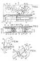
In der Zeichnung ist ein Ausführungsbeispiel der Erfindung schematisch dargestellt. Es zeigt:
- Fig. 1 eine schaubildliche Ansicht des Gerätes mit eingeseizter Injektionsspritze in geöffnetem Zustand,
- Fig. 2 eine Draufsicht des Vorschubwerkes bei abgenommenem Gehäusedeckel,
- Flg. 3 eine Ansicht des Vorschubwerkes und des Uhrwerkes, gesehen in Richtung des Pfeiles A in Fig. 2,
- Fig. 3a die Einrichtung zum Aus- bzw. Einkuppeln des Vorschubwerkes mit der Zahnstange in vergrössertem Massstab,
- Fig. 4 das Schaltrad mit einem Teil des Hemmankers in vergrössertem Massstab,
- Fig. 5 einen Einblick in das Gehäuse, gesehen in Richtung des Pfeiles B in Fig. 3,
- Fig. 6 einen Schnitt längs der Linie VI-VI in Fig. 5,
- Fig. 7 die Scheibenanordnung nach Fig. 6 in auseinandergezogenem Zustand,
- Fig. 8 die mittlere Scheibe der Scheibenanordnung nach Fig. 7 In anderer Stellung.
- 1 is a perspective view of the device with an injection syringe in the open state,
- 2 is a plan view of the feed mechanism with the housing cover removed,
- Flg. 3 is a view of the feed mechanism and the clock mechanism, viewed in the direction of arrow A in FIG. 2,
- 3a shows the device for disengaging or engaging the feed mechanism with the rack on an enlarged scale,
- 4 the ratchet wheel with part of the escapement armature on an enlarged scale,
- 5 shows an insight into the housing, seen in the direction of arrow B in FIG. 3,
- 6 shows a section along the line VI-VI in FIG. 5,
- 7 shows the pane arrangement according to FIG. 6 in an exploded state,
- Fig. 8, the middle disc of the disc assembly of FIG. 7 in a different position.
Das Gerät für Dauerinfusionen besteht gemäss Fig. 1 aus einem Gehäuse 1, das eine zur Seite hin offene Auflage 2 für eine Injektionsspritze 3, z. B. eine Einmal-Spritze aufweist. In die Spritzenauflage 2 ragt ein Arm 4 einer innerhalb des Gehäuses mit einem Vorschubantrieb koppelbaren Zahnstange. Der Arm 4 drückt gegen einen Stössel 3A der Injektionsspritze 3. Zum Verschluss der Spritzenauflage 2 dient eine Abdeckung 5. Diese ist als Winkelplatte gestaltet und bei 6 schwenkbar an dem Gehäuse gelagert. Der Drehpunkt der Abdeckung 5 ist so an dem Gehäuse angeordnet, dass immer das vordere Ende der Injektionsspritze 3 zuerst freigegeben wird, wenn die Abdeckung 5 zur Öffnung in Richtung des Pfeiles A verschwenkt wird. Fingerausnehmungen 7 erleichtern die Handhabung des Gerätes.According to FIG. 1, the device for continuous infusions consists of a
Gemäss der Erfindung zeichnet sich das Gerät dadurch aus, dass für das Uhrwerk und für das Vorschubwerk jeweils ein getrennter Kraftfluss vorgesehen ist. Zu diesem Zweck ist der Mechanismus des Uhrwerkes auf einer Seite der Längsmittelebene des Gehäuses angeordnet, während sich der Mechanismus des Vorschubwerkes auf der anderen Seite der Längsmittelebene des Gehäuses befindet (Fig. 3).According to the invention, the device is characterized in that a separate power flow is provided for the clockwork and for the feed mechanism. For this purpose, the mechanism of the clockwork is arranged on one side of the longitudinal center plane of the housing, while the mechanism of the feed mechanism is on the other side of the longitudinal center plane of the housing (FIG. 3).
Das Uhrwerk befindet sich bei der Darstellung nach Fig. 3 auf der Unterseite des Gehäuses. Es besteht in üblicher Weise aus einer Spiralzugfeder 8, deren Kraft über ein Zahnrad 18, ein Minutenrad 9, ein Kleinbodenrad 10 und ein Sekundenrad 11 auf einen Gang 12 übertragen wird. Die Spiralzugfeder 8 steht über ein Zahnrad 14 und eine Teilzahnscheibe 15 mit einer Aufzugswelle 13 in Verbindung. Die Aufzugswelle 13 ist bei 6 drehfest mit der Abdeckung 5 des Gehäuses verbunden, so dass bei Verschwenkung der Abdekkung 5 die Spiralzugfeder 8 aufgezogen wird.3 is located on the underside of the housing. It consists in the usual way of a
Die Aufzugswelle 13 wirkt auch auf eine dem Vorschubwerk zugeordnete Spiralzugfeder 16, die koaxial zu der Spiralzugfeder 8 auf einer Welle 17 angeordnet ist. Beide Spiralzugfedern 8 und 16 werden auf diese Weise bei Verschwenken der Abdeckung 5 gleichmässig aufgezogen. Um sicherzustellen, dass der Deckel immer um 180° verschwenkt wird, damit sowohl das Uhrwerk als auch das Vorschubwerk stets voll gespannt ist, ist die in den Fig. 6-8 veranschaulichte Scheibenanordnung vorgesehen.The
Eine teilweise schrägverzahnte Scheibe 19 ist fest mit der Abdeckung 5 verbunden, so dass sie sich bei Verschwenkung der Abdeckung 5 mitbewegt. Diese schrägverzahnte Scheibe 19 trägt einen quergerichteten Zapfen 20, der durch einen Bogenschlitz 21 in einer zweiten Scheibe 22 hindurchragt, die nur um ein kleines Winkelstück drehbar ist und eine umfangsmässige Aussparung 23 aufweist. Koaxial zu diesen beiden Scheiben 19 und 22 ist eine dritte teilverzahnte Scheibe 24 vorgesehen. In dieser ist ein Bogenschlitz 25 ausgebildet, der etwas länger als der Bogenschlitz 21 der Scheibe 22 ist und durch den ebenfalls der Zapfen 20 hindurchragt. Beim Verschwenken der Abdeckung 5 zum Aufziehen des Uhrwerkes nimmt der Zapfen 20 die Scheibe 24 mit, und ihr Zahnsegment 26 überträgt die Schwenkbewegung der Abdeckung 5 über ein Zahnrad 28 (Fig. 3) auf die Welle 17, die die beiden Spiralzugfedern 8 und 16 trägt. In jeder Phase der Öffnungsverschwenkung der Abdeckung 5 sperrt der Zusammengriff der Schrägverzahnung der Scheibe 19 und der Aussparung 23 in der Scheibe 22 mit einer federbelasteten Klinke 29 ein Zurückdrehen der Abdeckung 5 in die geschlossene Stellung. Erst bei Verschwenkung um 180° und dementsprechenden vollen Aufzug der beiden Spiralzugfedern wird die Klinke 29 durch die Nockenfläche 30 der Scheibe 22 ausgerastet und die Abdeckung kann frei in die Schliessstellung zurückgeschwenkt werden. Die Drehbewegung der Scheibe 22 um einen kleinen Winkel a ist dadurch möglich, dass der Bogenschlitz 25 der Scheibe 24 etwas länger ist als der Bogenschlitz 21 der Scheibe 22.A partially helically
Die Kraft der Spiralzugfeder 16 des Vorschubwerkes wird über ein Zahnrad 31 und eine nur andeutungsweise gezeichnete Übersetzung 32 auf ein Ritzel 33 übertragen, das mit einer Zahnstange 34 zusammenwirkt, deren Arm 4 gegen den Stössel 3A der Injektionsspritze 3 angreift.The force of the
Falls die Spritze 3 vor Ablauf der Gesamtinfusionszeit aus irgendwelchen Gründen aus der Spritzenauflage 2 herausgenommen werden soll, ist es zweckmässig, den Vorschub der Zahnstange 34 bis zum Wiedereinsetzen der Spritze 3 zu unterbrechen. Dies geschieht, indem bei aufgeklappter Abdeckung 5 die Zahnstange 34 automatisch ausser Eingriff mit dem Ritzel 33 gebracht wird. Zu diesem Zweck dient die in Fig. 3A herausgezeichnet veranschaulichte Einrichtung. Eine Nockenscheibe 35, die mit der Abdeckung 5 drehfest verbunden ist, wirkt über einen Federbügel 36 oder dergleichen auf einen Kipphebel 37, der als Träger für die Zahnstange 34 dient. Das eine Ende des Kipphebels 37 ist bei 38 schwenkbar mit dem Gehäuse 1 verbunden (Fig. 2), während sein anderes Ende unter der Wirkung einer Schraubenfeder 39 steht, die bei 40 fest mit dem Gehäuse verbunden ist (Fig. 3A). Die Zahnstange 34 ist zwischen zwei Stangen 41, von denen nur eine in Fig. 2 veranschaulicht ist, geführt, deren Enden an dem Kipphebel 37 befestigt sind. Bei geschlossenem Deckel ergibt sich die in Fig. 3A gezeigte Stellung, in der die Abflachung der Nockenscheibe 35 über den Bügel 36 den Kipphebel 37 in einer Stellung hält, in der das Vorschubwerk mit der Zahnstange 34 gekoppelt ist. Wird die Abdekkung 5 geöffnet, so drückt die Rundung der Nokkenscheibe 35 gegen den Bügel 36, und gegen die Wirkung der Schraubenfeder 39 bewegt sich der Kipphebel 37 in Richtung der Pfeiles C in Fig. 3A, wodurch das Vorschubwerk ausgekuppelt wird.If the
Das eingekuppelte Vorschubwerk wird von dem Uhrwerk gesteuert. Der Steuermechanismus weist einen Exzenter 411 auf der Welle 42 des Sekundenrades 11 auf. Mit dem Exzenter 411 greift eine Gabel 43 eines Hemmankers 44 zusammen, der auf einer Ankerwelle 45 schwenkbar gelagert ist und an seinem unteren Arm zwei Anschlagnasen 46 aufweist.The engaged feed mechanism is controlled by the clockwork. The control mechanism has an eccentric 411 on the shaft 42 of the
Die Anschlagnasen 46 des Hemmankers 44 wirken mit Flügeln eines Schaltrades 50 zusammen (Fig. 4), das über ein Zahnrad 60 und eine Übersetzung mit dem Ritzel 33 in Verbindung steht, das den Vorschub auf die Zahnstange 34 überträgt.The stop lugs 46 of the locking
Durch Hemmung des Schaltrades 50 bei Anschlag eines Flügels gegen eine Anschlagnase 46 des Hemmankers 44 wird jeweils die letzte Getriebestufe des Vorschubwerkes gesperrt und der Vorschub der Zahnstange 34 in kontinuierlich aufeinanderfolgende, gleichmässige Schrittchen aufgeteilt, deren Takt von dem Uhrwerk gesteuert wird.By inhibiting the
Zur Erzielung verschiedener umschaltbarer Vorschubgeschwindigkeiten ist der Hemmanker 44 auf seiner Welle 45 axial verstellbar. Zur axialen Verstellung dient eine gewellte Kurvenscheibe 47, die von aussen mittels eines Betätigungsteiles 48 (Fig. 1) von Hand drehbar ist und durch ihren Eingriff in einen Querschlitz 49 in der Ankerwelle 45 eine axiale Verstellung des Hemmankers 44 hervorruft, damit er mit unterschiedlich breiten Flügeln des Schaltrades 50 zusammengreifen kann.In order to achieve different switchable feed speeds, the
Bei dem gewählten Beispiel sind vier jeweils um 90° zueinander versetzte Flügel an dem Schaltrad 50 vorgesehen. Diese Flügel haben unterschiedliche Breite, und zwar ist der Flügel 51 halb so breit wie der ihm gegenüberliegende Flügel 52, während die beiden anderen Flügel 53 nochmals um die Hälfte schmaler als der Flügel 51 sind. Wird der Hemmanker 44 so eingestellt, dass er bei Umdrehung des Sekundenrades 11 alle vier Flügel 51-53 des Schaltrades 50 hemmt, so wird die Getriebestufe, auf der das Schaltrad 50 sitzt, pro Minute viermal gesperrt, das heisst, es ergeben sich kleine Vorschubstösse, und der vollständige Spritzenweg wird in der Zeit von 24 Stunden erreicht. Bei zwölf Stunden wird nur iAnAr7wpito Flügel (180°) gehemmt, so dass sich ein doppeltgrosser Vorschub ergibt, also zwölf Stunden Laufzeit auf die volle Hublänge. Bei Einstellung einer 6-Stunden-Dauerinfusion wird der Vorschub einmal pro 380° abgestoppt, und es wird eine 6-Stunden-Laufzeit auf 40 mm Vorschublänge erhalten. Eine Umschaltung auf einen anderen Vorschub ist mittels des Beätigungsteiles 48 während des Ablaufes möglich.In the example selected, four wings, each offset by 90 ° to one another, are provided on the
In Anpassung an andere Verhältnisse kann die Flügelanordnung des Schaltrades 50 anders als bei dem dargestellten Beispiel gewählt sein.In adaptation to other conditions, the wing arrangement of the
Claims (12)
Priority Applications (1)
| Application Number | Priority Date | Filing Date | Title |
|---|---|---|---|
| AT80100810TATE3368T1 (en) | 1979-02-22 | 1980-02-18 | DEVICE FOR CONTINUOUS INFUSIONS. |
Applications Claiming Priority (2)
| Application Number | Priority Date | Filing Date | Title |
|---|---|---|---|
| DE2906830ADE2906830C2 (en) | 1979-02-22 | 1979-02-22 | Device for continuous infusions |
| DE2906830 | 1979-02-22 |
Publications (2)
| Publication Number | Publication Date |
|---|---|
| EP0016343A1 EP0016343A1 (en) | 1980-10-01 |
| EP0016343B1true EP0016343B1 (en) | 1983-05-18 |
Family
ID=6063593
Family Applications (1)
| Application Number | Title | Priority Date | Filing Date |
|---|---|---|---|
| EP80100810AExpiredEP0016343B1 (en) | 1979-02-22 | 1980-02-18 | Continuous-infusion device |
Country Status (8)
| Country | Link |
|---|---|
| US (1) | US4300554A (en) |
| EP (1) | EP0016343B1 (en) |
| JP (1) | JPS55146165A (en) |
| AT (1) | ATE3368T1 (en) |
| DE (2) | DE2906830C2 (en) |
| DK (1) | DK73480A (en) |
| FI (1) | FI70796C (en) |
| NO (1) | NO148398C (en) |
Cited By (6)
| Publication number | Priority date | Publication date | Assignee | Title |
|---|---|---|---|---|
| FR2486403A1 (en)* | 1980-06-03 | 1982-01-15 | Albisser Anthony | PORTABLE DEVICE FOR SUBCUTANEOUS INJECTION OF A MEDICINAL PRODUCT |
| FR2522505A1 (en)* | 1981-12-21 | 1983-09-09 | Intermedicat Gmbh | PRESSURE INJECTION APPARATUS FOR MEDICAL APPLICATIONS |
| EP0170784A1 (en)* | 1984-06-05 | 1986-02-12 | Intermedicat GmbH | Syringe-pump |
| FR2572288A1 (en)* | 1984-10-26 | 1986-05-02 | Infors Gmbh | INFUSION PUMP |
| EP0230380A3 (en)* | 1986-01-16 | 1988-02-03 | Daltex Medical Sciences, Inc. | Mechanical drive system for syringe having manual advance and quick release |
| WO1989006145A1 (en)* | 1988-01-07 | 1989-07-13 | Bernard Hazon | Syringe-pushing device for ambulant administration of parenteral injections, with flow rate governed by the contents of the syringe |
Families Citing this family (140)
| Publication number | Priority date | Publication date | Assignee | Title |
|---|---|---|---|---|
| US4416662A (en)* | 1980-06-13 | 1983-11-22 | The United States Of America As Represented By The Department Of Health And Human Services | Roller infusion apparatus |
| US4447232A (en)* | 1982-05-21 | 1984-05-08 | Repro-Med Systems, Inc. | Spring-operated liquid-dispensing device |
| US4493704A (en)* | 1982-11-29 | 1985-01-15 | Oximetrix, Inc. | Portable fluid infusion apparatus |
| US4505702A (en)* | 1982-12-23 | 1985-03-19 | Alza Corporation | Manually operable rotary syringe |
| FR2551350B1 (en)* | 1983-09-02 | 1985-10-25 | Buffet Jacques | FLUID INJECTION DEVICE, SUITABLE FOR IMPLANTATION |
| DE3468173D1 (en)* | 1983-09-07 | 1988-02-04 | Disetronic Ag | Portable infusion apparatus |
| US4648872A (en)* | 1983-11-15 | 1987-03-10 | Kamen Dean L | Volumetric pump with replaceable reservoir assembly |
| JPS6083638U (en)* | 1983-11-16 | 1985-06-10 | アイ・ケイ・コ−チ株式会社 | Automatic liquid supply device for continuous eye drops |
| AU564699B2 (en)* | 1984-01-25 | 1987-08-20 | Imed Corporation | Hydraulic syringe device |
| RO86562A2 (en)* | 1984-01-27 | 1985-10-31 | Spitalul Judetean Laboratorul De Plante Medicinale Plante Vorel,Ro | VEGETABLE MEDICAMENTOUS COMPOSITION FOR THE TREATMENT OF HEPA-BILIARY AFFECTIONS |
| US4583973A (en)* | 1984-04-11 | 1986-04-22 | Robert Humphrey | Viscous fluid timed infusion device |
| US4602700A (en)* | 1984-06-15 | 1986-07-29 | Daltex Medical Sciences, Inc. | Fail-safe mechanical drive for syringe |
| GB8423749D0 (en)* | 1984-09-19 | 1984-10-24 | Sutherland I A | Powered infusion apparatus |
| DE3636948C1 (en)* | 1986-10-30 | 1987-05-07 | Braun Melsungen Ag | Spring winding gear for the running gear of a device with flow protection |
| US4921487A (en)* | 1988-09-21 | 1990-05-01 | Compagnie Financiere Saint. Nicolas | External device for injecting medicine |
| US5261882A (en)* | 1993-04-26 | 1993-11-16 | Sealfon Andrew I | Negator spring-powered syringe |
| US5336189A (en)* | 1993-08-23 | 1994-08-09 | Sealfon Andrew I | Combination IV pump and disposable syringe |
| DE19519278A1 (en)* | 1994-12-07 | 1997-06-12 | Wolfgang Dr Med Wagner | Measurement of, esp. glucose level, using suction cup |
| FR2775190B1 (en)* | 1998-02-23 | 2000-06-16 | Lhd Lab Hygiene Dietetique | DEVICE FOR FILLING A TANK WITH A LIQUID CONTAINING A PHARMACOLOGICALLY ACTIVE PRODUCT |
| GB9924780D0 (en) | 1999-10-21 | 1999-12-22 | Glaxo Group Ltd | Medicament dispenser |
| GB0006871D0 (en) | 2000-03-21 | 2000-05-10 | Wymark Ltd | A lubricating device |
| US6663602B2 (en) | 2000-06-16 | 2003-12-16 | Novo Nordisk A/S | Injection device |
| DE10046279A1 (en)* | 2000-09-19 | 2002-04-04 | Disetronic Licensing Ag | Device for the dosed administration of an injectable product |
| JP4350525B2 (en)* | 2002-03-18 | 2009-10-21 | イーライ リリー アンド カンパニー | Drug dispensing device with gear set giving mechanical advantages |
| AU2003245872A1 (en) | 2002-07-24 | 2004-02-09 | M 2 Medical A/S | An infusion pump system, an infusion pump unit and an infusion pump |
| US7527608B2 (en) | 2002-08-12 | 2009-05-05 | Lma North America, Inc. | Medication infusion and aspiration system and method |
| DE10240166A1 (en)* | 2002-08-30 | 2004-03-18 | Disetronic Licensing Ag | Injection syringe for dispensing insulin to treat diabetes has piston operated by flexible belt which is moved by manually-operated wheel with teeth which cooperate with catches set to give predetermined dose |
| DE10240165A1 (en)* | 2002-08-30 | 2004-03-18 | Disetronic Licensing Ag | Dispensing unit for use in infusion pumps comprises reservoir for infusion liquid fitted with spring-loaded piston, toothed wheel cooperating with locking bar to prevent piston moving |
| CN1726059A (en) | 2002-11-05 | 2006-01-25 | M2医药有限公司 | Disposable wearable insulin dispensing device, combination of the device and a program controller and method for controlling the operation of the device |
| WO2004056412A2 (en) | 2002-12-23 | 2004-07-08 | M2 Medical A/S | A disposable, wearable insulin dispensing device, a combination of such a device and a programming controller and a method of controlling the operation of such a device |
| AU2003291963A1 (en) | 2002-12-23 | 2004-07-14 | M 2 Medical A/S | Flexible piston rod |
| US7753879B2 (en) | 2004-01-29 | 2010-07-13 | M2 Group Holdings, Inc. | Disposable medicine dispensing device |
| EP1732629B1 (en)* | 2004-03-30 | 2019-04-24 | Eli Lilly And Company | Medication dispensing apparatus with spring-driven locking feature enabled by administration of final dose |
| DK1732628T3 (en)* | 2004-03-30 | 2011-10-24 | Lilly Co Eli | Medication dispenser with gear set with opening for a drive element |
| ATE444090T1 (en) | 2004-10-21 | 2009-10-15 | Novo Nordisk As | SELECTION MECHANISM FOR A ROTARY PIN |
| EP1877115A1 (en) | 2005-04-06 | 2008-01-16 | M 2 Medical A/S | An actuator |
| US20090043264A1 (en) | 2005-04-24 | 2009-02-12 | Novo Nordisk A/S | Injection Device |
| US8409142B2 (en) | 2005-09-26 | 2013-04-02 | Asante Solutions, Inc. | Operating an infusion pump system |
| DK1933902T3 (en) | 2005-09-26 | 2015-03-23 | Asante Solutions Inc | Infusion Pump WITH A DRIVE THAT HAVE AN PALLEGEME- AND CONGEST HAGE-COMBINATION |
| US7534226B2 (en) | 2005-09-26 | 2009-05-19 | M2 Group Holdings, Inc. | Dispensing fluid from an infusion pump system |
| US8551046B2 (en) | 2006-09-18 | 2013-10-08 | Asante Solutions, Inc. | Dispensing fluid from an infusion pump system |
| US8105279B2 (en) | 2005-09-26 | 2012-01-31 | M2 Group Holdings, Inc. | Dispensing fluid from an infusion pump system |
| US8057436B2 (en)* | 2005-09-26 | 2011-11-15 | Asante Solutions, Inc. | Dispensing fluid from an infusion pump system |
| WO2007056592A2 (en) | 2005-11-08 | 2007-05-18 | M2 Medical A/S | Method and system for manual and autonomous control of an infusion pump |
| US8475408B2 (en) | 2005-11-08 | 2013-07-02 | Asante Solutions, Inc. | Infusion pump system |
| CN101400394B (en)* | 2006-03-10 | 2012-07-04 | 诺沃-诺迪斯克有限公司 | An injection device having a gearing arrangement |
| JP5062768B2 (en) | 2006-03-10 | 2012-10-31 | ノボ・ノルデイスク・エー/エス | INJECTION DEVICE AND METHOD FOR REPLACING CARTRIDGE OF THE DEVICE |
| EP2316505B1 (en) | 2006-03-14 | 2017-01-18 | University Of Southern California | Mems device for delivery of therapeutic agents |
| ATE458517T1 (en) | 2006-05-16 | 2010-03-15 | Novo Nordisk As | TRANSMISSION MECHANISM FOR AN INJECTION DEVICE |
| JP5253387B2 (en) | 2006-05-18 | 2013-07-31 | ノボ・ノルデイスク・エー/エス | Injection device with mode locking means |
| BRPI0809265A2 (en) | 2007-03-23 | 2014-10-07 | Novo Nordisk As | INJECTION DEVICE INCLUDING A TIGHTENING NUT |
| US7833196B2 (en) | 2007-05-21 | 2010-11-16 | Asante Solutions, Inc. | Illumination instrument for an infusion pump |
| US7794426B2 (en) | 2007-05-21 | 2010-09-14 | Asante Solutions, Inc. | Infusion pump system with contamination-resistant features |
| US7892199B2 (en) | 2007-05-21 | 2011-02-22 | Asante Solutions, Inc. | Occlusion sensing for an infusion pump |
| US7981102B2 (en) | 2007-05-21 | 2011-07-19 | Asante Solutions, Inc. | Removable controller for an infusion pump |
| US7828528B2 (en) | 2007-09-06 | 2010-11-09 | Asante Solutions, Inc. | Occlusion sensing system for infusion pumps |
| US7717903B2 (en) | 2007-09-06 | 2010-05-18 | M2 Group Holdings, Inc. | Operating an infusion pump system |
| US7879026B2 (en) | 2007-09-07 | 2011-02-01 | Asante Solutions, Inc. | Controlled adjustment of medicine dispensation from an infusion pump device |
| US8287514B2 (en) | 2007-09-07 | 2012-10-16 | Asante Solutions, Inc. | Power management techniques for an infusion pump system |
| US7935076B2 (en) | 2007-09-07 | 2011-05-03 | Asante Solutions, Inc. | Activity sensing techniques for an infusion pump system |
| US8032226B2 (en) | 2007-09-07 | 2011-10-04 | Asante Solutions, Inc. | User profile backup system for an infusion pump device |
| US9345836B2 (en) | 2007-10-02 | 2016-05-24 | Medimop Medical Projects Ltd. | Disengagement resistant telescoping assembly and unidirectional method of assembly for such |
| BRPI0817907B8 (en) | 2007-10-02 | 2021-06-22 | Lamodel Ltd | apparatus for administering a substance to an individual |
| US7967795B1 (en) | 2010-01-19 | 2011-06-28 | Lamodel Ltd. | Cartridge interface assembly with driving plunger |
| US9656019B2 (en) | 2007-10-02 | 2017-05-23 | Medimop Medical Projects Ltd. | Apparatuses for securing components of a drug delivery system during transport and methods of using same |
| US10420880B2 (en) | 2007-10-02 | 2019-09-24 | West Pharma. Services IL, Ltd. | Key for securing components of a drug delivery system during assembly and/or transport and methods of using same |
| WO2009086112A2 (en) | 2007-12-20 | 2009-07-09 | University Of Southern California | Apparatus and methods for delivering therapeutic agents |
| JP5719767B2 (en) | 2008-05-08 | 2015-05-20 | ミニパンプス, エルエルシー | Implantable pump and cannula therefor |
| US8486278B2 (en) | 2008-05-08 | 2013-07-16 | Minipumps, Llc | Drug-delivery pumps and methods of manufacture |
| US9849238B2 (en) | 2008-05-08 | 2017-12-26 | Minipumps, Llc | Drug-delivery pump with intelligent control |
| US7959598B2 (en) | 2008-08-20 | 2011-06-14 | Asante Solutions, Inc. | Infusion pump systems and methods |
| US9393369B2 (en) | 2008-09-15 | 2016-07-19 | Medimop Medical Projects Ltd. | Stabilized pen injector |
| US12097357B2 (en) | 2008-09-15 | 2024-09-24 | West Pharma. Services IL, Ltd. | Stabilized pen injector |
| US8287487B2 (en)* | 2008-10-15 | 2012-10-16 | Asante Solutions, Inc. | Infusion pump system and methods |
| US20100145305A1 (en)* | 2008-11-10 | 2010-06-10 | Ruth Alon | Low volume accurate injector |
| US8152779B2 (en)* | 2008-12-30 | 2012-04-10 | Medimop Medical Projects Ltd. | Needle assembly for drug pump |
| EP2429615A1 (en)* | 2009-05-13 | 2012-03-21 | Sanofi-Aventis Deutschland GmbH | A fluid drug delivery system and method for manufacturing a drug delivery system |
| KR101697388B1 (en) | 2009-08-18 | 2017-01-17 | 미니펌프스, 엘엘씨 | Electrolytic drug-delivery pump with adaptive control |
| US8157769B2 (en) | 2009-09-15 | 2012-04-17 | Medimop Medical Projects Ltd. | Cartridge insertion assembly for drug delivery system |
| USD810279S1 (en) | 2009-09-15 | 2018-02-13 | Medimop Medical Projects Ltd. | Injector device |
| US10071196B2 (en) | 2012-05-15 | 2018-09-11 | West Pharma. Services IL, Ltd. | Method for selectively powering a battery-operated drug-delivery device and device therefor |
| US10071198B2 (en) | 2012-11-02 | 2018-09-11 | West Pharma. Servicees IL, Ltd. | Adhesive structure for medical device |
| US8348898B2 (en) | 2010-01-19 | 2013-01-08 | Medimop Medical Projects Ltd. | Automatic needle for drug pump |
| CN103108665A (en)* | 2010-04-20 | 2013-05-15 | 迷你泵有限责任公司 | Electrolytically driven drug pump devices |
| EP2569031B1 (en) | 2010-05-10 | 2017-10-11 | Medimop Medical Projects Ltd. | Low volume accurate injector |
| USD669165S1 (en) | 2010-05-27 | 2012-10-16 | Asante Solutions, Inc. | Infusion pump |
| EP2468341A1 (en)* | 2010-12-21 | 2012-06-27 | Sanofi-Aventis Deutschland GmbH | Auto-injector |
| US8852152B2 (en) | 2011-02-09 | 2014-10-07 | Asante Solutions, Inc. | Infusion pump systems and methods |
| US9192716B2 (en)* | 2011-03-16 | 2015-11-24 | Sanofi-Aventis Deutschland Gmbh | Drive mechanism for a drug delivery device and drug delivery device |
| US8454581B2 (en) | 2011-03-16 | 2013-06-04 | Asante Solutions, Inc. | Infusion pump systems and methods |
| USD702834S1 (en) | 2011-03-22 | 2014-04-15 | Medimop Medical Projects Ltd. | Cartridge for use in injection device |
| WO2012127365A1 (en)* | 2011-03-22 | 2012-09-27 | Pfizer Health Ab | Cover for housing a syringe, assembly comprising such cover, pen-injector comprising such assembly and method for forming a pen-injector |
| US8585657B2 (en) | 2011-06-21 | 2013-11-19 | Asante Solutions, Inc. | Dispensing fluid from an infusion pump system |
| JP6069351B2 (en) | 2011-12-29 | 2017-02-01 | ノボ・ノルデイスク・エー/エス | Torsion spring type automatic syringe with dial-up / dial-down administration mechanism |
| US9072827B2 (en) | 2012-03-26 | 2015-07-07 | Medimop Medical Projects Ltd. | Fail safe point protector for needle safety flap |
| US9352095B2 (en) | 2012-04-06 | 2016-05-31 | Baxter International, Inc. | Container system |
| US9421323B2 (en) | 2013-01-03 | 2016-08-23 | Medimop Medical Projects Ltd. | Door and doorstop for portable one use drug delivery apparatus |
| DE202013000411U1 (en)* | 2013-01-16 | 2013-01-24 | H & B Electronic Gmbh & Co. Kg | Continuous infusion device |
| WO2014145548A2 (en)* | 2013-03-15 | 2014-09-18 | Concert Medical, Llc | Method and system for controllably administering fluid to a patient and/or for controllably withdrawing fluid from the patient |
| US9011164B2 (en) | 2013-04-30 | 2015-04-21 | Medimop Medical Projects Ltd. | Clip contact for easy installation of printed circuit board PCB |
| US9561324B2 (en) | 2013-07-19 | 2017-02-07 | Bigfoot Biomedical, Inc. | Infusion pump system and method |
| TWI569832B (en) | 2013-10-23 | 2017-02-11 | 卡貝歐洲有限公司 | Medicament delivery device |
| US10569015B2 (en) | 2013-12-02 | 2020-02-25 | Bigfoot Biomedical, Inc. | Infusion pump system and method |
| CN104474602B (en)* | 2014-12-04 | 2017-01-11 | 广西大学 | Constant-force spring type medical infusion apparatus |
| US10293120B2 (en) | 2015-04-10 | 2019-05-21 | West Pharma. Services IL, Ltd. | Redundant injection device status indication |
| US9878097B2 (en) | 2015-04-29 | 2018-01-30 | Bigfoot Biomedical, Inc. | Operating an infusion pump system |
| US10149943B2 (en) | 2015-05-29 | 2018-12-11 | West Pharma. Services IL, Ltd. | Linear rotation stabilizer for a telescoping syringe stopper driverdriving assembly |
| CN113181477B (en) | 2015-06-04 | 2023-07-14 | 麦迪麦珀医疗工程有限公司 | Cartridge insertion for drug delivery device |
| US10576207B2 (en) | 2015-10-09 | 2020-03-03 | West Pharma. Services IL, Ltd. | Angled syringe patch injector |
| US10086145B2 (en) | 2015-09-22 | 2018-10-02 | West Pharma Services Il, Ltd. | Rotation resistant friction adapter for plunger driver of drug delivery device |
| US9987432B2 (en) | 2015-09-22 | 2018-06-05 | West Pharma. Services IL, Ltd. | Rotation resistant friction adapter for plunger driver of drug delivery device |
| US11318254B2 (en) | 2015-10-09 | 2022-05-03 | West Pharma. Services IL, Ltd. | Injector needle cap remover |
| AU2016385454B2 (en) | 2016-01-05 | 2021-12-16 | Bigfoot Biomedical, Inc. | Operating multi-modal medicine delivery systems |
| US10449294B1 (en) | 2016-01-05 | 2019-10-22 | Bigfoot Biomedical, Inc. | Operating an infusion pump system |
| HK1256995A1 (en) | 2016-01-14 | 2019-10-11 | Bigfoot Biomedical, Inc. | Occlusion resolution in medication delivery devices, systems, and methods |
| EP3711793B1 (en) | 2016-01-21 | 2021-12-01 | West Pharma Services IL, Ltd. | A method of connecting a cartridge to an automatic injector |
| JP6885960B2 (en) | 2016-01-21 | 2021-06-16 | ウェスト ファーマ サービシーズ イスラエル リミテッド | Drug delivery device with visual indicators |
| US10646643B2 (en) | 2016-01-21 | 2020-05-12 | West Pharma. Services IL, Ltd. | Needle insertion and retraction mechanism |
| CN105477737B (en)* | 2016-02-03 | 2018-12-28 | 广州市安辅健医疗器械有限公司 | A kind of portable infusion apparatus |
| USD809134S1 (en) | 2016-03-10 | 2018-01-30 | Bigfoot Biomedical, Inc. | Infusion pump assembly |
| US11389597B2 (en) | 2016-03-16 | 2022-07-19 | West Pharma. Services IL, Ltd. | Staged telescopic screw assembly having different visual indicators |
| US10376647B2 (en) | 2016-03-18 | 2019-08-13 | West Pharma. Services IL, Ltd. | Anti-rotation mechanism for telescopic screw assembly |
| US10350348B2 (en) | 2016-05-23 | 2019-07-16 | Lifescan Ip Holdings, Llc | Manually actuated infusion device with display |
| CN109310831B (en) | 2016-06-02 | 2021-11-23 | 西医药服务以色列有限公司 | Three position needle retraction |
| JP6708782B2 (en)* | 2016-08-01 | 2020-06-10 | ウェスト ファーマ サービシーズ イスラエル リミテッド | Method of deploying an auto-injector type device and cartridge |
| JP7059251B2 (en) | 2016-08-01 | 2022-04-25 | ウェスト ファーマ サービシーズ イスラエル リミテッド | A spring that prevents the door from closing halfway |
| US11338090B2 (en) | 2016-08-01 | 2022-05-24 | West Pharma. Services IL, Ltd. | Anti-rotation cartridge pin |
| US10602716B2 (en)* | 2016-08-17 | 2020-03-31 | Crystal Spring Colony Farms Ltd. | Feeding apparatus for animals |
| AU2017335762B2 (en) | 2016-09-27 | 2022-03-17 | Bigfoot Biomedical, Inc. | Medicine injection and disease management systems, devices, and methods |
| USD836769S1 (en) | 2016-12-12 | 2018-12-25 | Bigfoot Biomedical, Inc. | Insulin delivery controller |
| EP3500161A4 (en) | 2016-12-12 | 2020-01-08 | Bigfoot Biomedical, Inc. | ALARMS AND WARNINGS FOR MEDICINE DELIVERY DEVICES AND RELATED SYSTEMS AND METHODS |
| US10960132B1 (en)* | 2017-01-31 | 2021-03-30 | Verily Life Sciences Llc | Clutched delivery device |
| EP3630226A1 (en) | 2017-05-30 | 2020-04-08 | West Pharma. Services Il, Ltd. | Modular drive train for wearable injector |
| USD839294S1 (en) | 2017-06-16 | 2019-01-29 | Bigfoot Biomedical, Inc. | Display screen with graphical user interface for closed-loop medication delivery |
| EP3651647A1 (en) | 2017-07-13 | 2020-05-20 | Bigfoot Biomedical, Inc. | Multi-scale display of blood glucose information |
| US11517664B2 (en)* | 2017-07-20 | 2022-12-06 | Flex Ltd. | Wire and pulley clock mechanism flow regulator |
| JP7402799B2 (en) | 2017-12-22 | 2023-12-21 | ウェスト ファーマ サービシーズ イスラエル リミテッド | Syringes available with different cartridge sizes |
| US11278669B2 (en) | 2020-01-21 | 2022-03-22 | Repro Med Systems, Inc. | Gear-driven infusion assemblies, systems, and methods |
| CN114272471B (en)* | 2021-12-29 | 2024-01-16 | 中山大学孙逸仙纪念医院 | Injection device and injection device |
| CN120225233A (en)* | 2022-09-30 | 2025-06-27 | 英赛罗公司 | Dual wheel actuator |
Family Cites Families (8)
| Publication number | Priority date | Publication date | Assignee | Title |
|---|---|---|---|---|
| US2602446A (en)* | 1950-02-27 | 1952-07-08 | Antonina S Glass | Automatic medical injection apparatus |
| US2896621A (en)* | 1957-04-16 | 1959-07-28 | John J Rodrigues | Motor driven syringe |
| GB1026593A (en)* | 1961-07-24 | 1966-04-20 | Alan Richard Nash | Drive means for syringes and the like |
| US3415419A (en)* | 1966-10-27 | 1968-12-10 | Jewett | Fluid administering system |
| DE2112654A1 (en)* | 1971-03-16 | 1972-10-05 | Southdown Medical Developments | Device for actuating a syringe |
| US3886938A (en)* | 1973-10-23 | 1975-06-03 | Scala Anthony | Power operated fluid infusion device |
| FR2276841A1 (en)* | 1974-07-03 | 1976-01-30 | Bhavsar Guy | Automatic injection syringe appts. for therapeutic liqs. - with electronic controlled step by step motor |
| US4059110A (en)* | 1976-10-07 | 1977-11-22 | Timex Corporation | Clockwork driven hypodermic syringe |
- 1979
- 1979-02-22DEDE2906830Apatent/DE2906830C2/ennot_activeExpired
- 1980
- 1980-02-14USUS06/121,494patent/US4300554A/ennot_activeExpired - Lifetime
- 1980-02-18EPEP80100810Apatent/EP0016343B1/ennot_activeExpired
- 1980-02-18DEDE8080100810Tpatent/DE3063232D1/ennot_activeExpired
- 1980-02-18ATAT80100810Tpatent/ATE3368T1/ennot_activeIP Right Cessation
- 1980-02-20DKDK73480Apatent/DK73480A/ennot_activeApplication Discontinuation
- 1980-02-21NONO800468Apatent/NO148398C/enunknown
- 1980-02-21FIFI800518Apatent/FI70796C/ennot_activeIP Right Cessation
- 1980-02-22JPJP2216880Apatent/JPS55146165A/enactiveGranted
Cited By (7)
| Publication number | Priority date | Publication date | Assignee | Title |
|---|---|---|---|---|
| FR2486403A1 (en)* | 1980-06-03 | 1982-01-15 | Albisser Anthony | PORTABLE DEVICE FOR SUBCUTANEOUS INJECTION OF A MEDICINAL PRODUCT |
| FR2522505A1 (en)* | 1981-12-21 | 1983-09-09 | Intermedicat Gmbh | PRESSURE INJECTION APPARATUS FOR MEDICAL APPLICATIONS |
| EP0170784A1 (en)* | 1984-06-05 | 1986-02-12 | Intermedicat GmbH | Syringe-pump |
| FR2572288A1 (en)* | 1984-10-26 | 1986-05-02 | Infors Gmbh | INFUSION PUMP |
| EP0230380A3 (en)* | 1986-01-16 | 1988-02-03 | Daltex Medical Sciences, Inc. | Mechanical drive system for syringe having manual advance and quick release |
| WO1989006145A1 (en)* | 1988-01-07 | 1989-07-13 | Bernard Hazon | Syringe-pushing device for ambulant administration of parenteral injections, with flow rate governed by the contents of the syringe |
| US5139484A (en)* | 1988-01-07 | 1992-08-18 | Bernard Hazon | Ambulatory syringe-pusher device for parenteral injections with output servo-controlled by the contents of the syringe |
Also Published As
| Publication number | Publication date |
|---|---|
| DE2906830C2 (en) | 1981-07-16 |
| JPS55146165A (en) | 1980-11-14 |
| US4300554A (en) | 1981-11-17 |
| NO148398C (en) | 1983-10-05 |
| NO800468L (en) | 1980-08-25 |
| DK73480A (en) | 1980-08-23 |
| FI70796C (en) | 1986-10-27 |
| FI70796B (en) | 1986-07-18 |
| FI800518A7 (en) | 1980-08-23 |
| DE3063232D1 (en) | 1983-07-07 |
| ATE3368T1 (en) | 1983-06-15 |
| EP0016343A1 (en) | 1980-10-01 |
| NO148398B (en) | 1983-06-27 |
| JPS6225390B2 (en) | 1987-06-02 |
| DE2906830B1 (en) | 1980-08-21 |
Similar Documents
| Publication | Publication Date | Title |
|---|---|---|
| EP0016343B1 (en) | Continuous-infusion device | |
| EP1833535B1 (en) | Device for the dosed administration of a fluid product comprising a torsion spring drive | |
| EP1075292B1 (en) | Injection device | |
| DE60120954T2 (en) | DRUG DELIVERY EQUIPPED WITH A DISPOSABLE MECHANISM | |
| DE10237258B4 (en) | injection device | |
| DE69214670T2 (en) | AUTOMATIC PEN-SHAPED SYRINGE | |
| DE69319379T2 (en) | Syringe pump with preloaded lockable syringe clamp | |
| EP1648540A2 (en) | Injection device | |
| EP0581788B1 (en) | Injection device | |
| DE69305680T2 (en) | Control system for syringe pump | |
| DE20023819U1 (en) | Dose setting limiter, for injection devices e.g. syringes, comprises a driver with a track, having a length corresponding to the amount of medicament in the cartridge, that is engaged with a track follower coupled to dose setting element | |
| EP1140260A1 (en) | Injection device | |
| EP3795194A1 (en) | Injection device for administering or transporting fluid product | |
| CH706567A2 (en) | Improved device to set a dose a limiting mechanism for an apparatus for administering a product. | |
| DE102004042581A1 (en) | Car pen for two-chamber ampoule | |
| DE202009019077U1 (en) | Drive mechanism for a drug delivery device and drug delivery device | |
| DE3783392T2 (en) | External drug injection device. | |
| EP1838368B1 (en) | Injection device with a dosing mechanism | |
| EP3016698B1 (en) | Continuous infusion device | |
| WO2003097131A1 (en) | Device for guiding a drive | |
| DE1224144B (en) | Self-release mechanism that can be attached to photographic cameras | |
| DE1206303B (en) | Time mechanism, especially self-release mechanism for photographic shutters | |
| WO2011057677A1 (en) | Administering device having overload protection during dose adjustment | |
| DE310511C (en) | ||
| DE962994C (en) | Starter for time drives |
Legal Events
| Date | Code | Title | Description |
|---|---|---|---|
| PUAI | Public reference made under article 153(3) epc to a published international application that has entered the european phase | Free format text:ORIGINAL CODE: 0009012 | |
| AK | Designated contracting states | Designated state(s):AT BE CH DE FR GB IT LU NL SE | |
| 17P | Request for examination filed | Effective date:19801104 | |
| ITF | It: translation for a ep patent filed | ||
| GRAA | (expected) grant | Free format text:ORIGINAL CODE: 0009210 | |
| AK | Designated contracting states | Designated state(s):AT BE CH DE FR GB IT LU NL SE | |
| REF | Corresponds to: | Ref document number:3368 Country of ref document:AT Date of ref document:19830615 Kind code of ref document:T | |
| REF | Corresponds to: | Ref document number:3063232 Country of ref document:DE Date of ref document:19830707 | |
| ET | Fr: translation filed | ||
| PGFP | Annual fee paid to national office [announced via postgrant information from national office to epo] | Ref country code:FR Payment date:19840120 Year of fee payment:5 | |
| PG25 | Lapsed in a contracting state [announced via postgrant information from national office to epo] | Ref country code:LU Free format text:LAPSE BECAUSE OF NON-PAYMENT OF DUE FEES Effective date:19840229 | |
| PLBE | No opposition filed within time limit | Free format text:ORIGINAL CODE: 0009261 | |
| STAA | Information on the status of an ep patent application or granted ep patent | Free format text:STATUS: NO OPPOSITION FILED WITHIN TIME LIMIT | |
| PGFP | Annual fee paid to national office [announced via postgrant information from national office to epo] | Ref country code:SE Payment date:19840331 Year of fee payment:5 Ref country code:BE Payment date:19840331 Year of fee payment:5 | |
| PGFP | Annual fee paid to national office [announced via postgrant information from national office to epo] | Ref country code:CH Payment date:19840518 Year of fee payment:5 | |
| 26N | No opposition filed | ||
| PGFP | Annual fee paid to national office [announced via postgrant information from national office to epo] | Ref country code:DE Payment date:19850321 Year of fee payment:6 | |
| PGFP | Annual fee paid to national office [announced via postgrant information from national office to epo] | Ref country code:LU Payment date:19860303 Year of fee payment:7 | |
| PGFP | Annual fee paid to national office [announced via postgrant information from national office to epo] | Ref country code:AT Payment date:19870210 Year of fee payment:8 | |
| PGFP | Annual fee paid to national office [announced via postgrant information from national office to epo] | Ref country code:NL Payment date:19870228 Year of fee payment:8 | |
| PG25 | Lapsed in a contracting state [announced via postgrant information from national office to epo] | Ref country code:AT Effective date:19880218 | |
| PG25 | Lapsed in a contracting state [announced via postgrant information from national office to epo] | Ref country code:SE Effective date:19880219 | |
| PG25 | Lapsed in a contracting state [announced via postgrant information from national office to epo] | Ref country code:CH Effective date:19880229 | |
| BERE | Be: lapsed | Owner name:INTERMEDICAT G.M.B.H. Effective date:19880228 | |
| PG25 | Lapsed in a contracting state [announced via postgrant information from national office to epo] | Ref country code:NL Effective date:19880901 | |
| NLV4 | Nl: lapsed or anulled due to non-payment of the annual fee | ||
| PG25 | Lapsed in a contracting state [announced via postgrant information from national office to epo] | Ref country code:FR Free format text:LAPSE BECAUSE OF NON-PAYMENT OF DUE FEES Effective date:19881028 | |
| REG | Reference to a national code | Ref country code:CH Ref legal event code:PL | |
| PG25 | Lapsed in a contracting state [announced via postgrant information from national office to epo] | Ref country code:DE Effective date:19881101 | |
| GBPC | Gb: european patent ceased through non-payment of renewal fee | ||
| PG25 | Lapsed in a contracting state [announced via postgrant information from national office to epo] | Ref country code:GB Free format text:LAPSE BECAUSE OF NON-PAYMENT OF DUE FEES Effective date:19881118 | |
| REG | Reference to a national code | Ref country code:FR Ref legal event code:ST | |
| PG25 | Lapsed in a contracting state [announced via postgrant information from national office to epo] | Ref country code:BE Effective date:19890228 | |
| EUG | Se: european patent has lapsed | Ref document number:80100810.3 Effective date:19880927 |