EP0016338A1 - Tensioning device for a compression plate for use in joining bone fragments under pressure - Google Patents
Tensioning device for a compression plate for use in joining bone fragments under pressureDownload PDFInfo
- Publication number
- EP0016338A1 EP0016338A1EP80100776AEP80100776AEP0016338A1EP 0016338 A1EP0016338 A1EP 0016338A1EP 80100776 AEP80100776 AEP 80100776AEP 80100776 AEP80100776 AEP 80100776AEP 0016338 A1EP0016338 A1EP 0016338A1
- Authority
- EP
- European Patent Office
- Prior art keywords
- clamping
- pressure plate
- clamping block
- clamping device
- screw
- Prior art date
- Legal status (The legal status is an assumption and is not a legal conclusion. Google has not performed a legal analysis and makes no representation as to the accuracy of the status listed.)
- Granted
Links
- 210000000988bone and boneAnatomy0.000titleclaimsabstractdescription36
- 239000012634fragmentSubstances0.000titleclaimsabstractdescription18
- 238000007906compressionMethods0.000titledescription10
- 230000006835compressionEffects0.000titledescription9
- 230000003993interactionEffects0.000claims1
- 208000027418Wounds and injuryDiseases0.000description6
- 238000000034methodMethods0.000description3
- 206010064211Bone fragmentationDiseases0.000description2
- 206010003694AtrophyDiseases0.000description1
- 241001269235DanisSpecies0.000description1
- 206010023201Joint contractureDiseases0.000description1
- 208000012886VertigoDiseases0.000description1
- 230000006978adaptationEffects0.000description1
- 230000037444atrophyEffects0.000description1
- 230000007797corrosionEffects0.000description1
- 238000005260corrosionMethods0.000description1
- 208000037265diseases, disorders, signs and symptomsDiseases0.000description1
- 208000035475disorderDiseases0.000description1
- 238000006073displacement reactionMethods0.000description1
- 230000000694effectsEffects0.000description1
- 230000035876healingEffects0.000description1
- 239000007943implantSubstances0.000description1
- 239000002655kraft paperSubstances0.000description1
- 238000004519manufacturing processMethods0.000description1
- 210000003205muscleAnatomy0.000description1
- 230000002265preventionEffects0.000description1
- 210000002023somiteAnatomy0.000description1
- 210000001519tissueAnatomy0.000description1
Images


Classifications
- A—HUMAN NECESSITIES
- A61—MEDICAL OR VETERINARY SCIENCE; HYGIENE
- A61B—DIAGNOSIS; SURGERY; IDENTIFICATION
- A61B17/00—Surgical instruments, devices or methods
- A61B17/56—Surgical instruments or methods for treatment of bones or joints; Devices specially adapted therefor
- A61B17/58—Surgical instruments or methods for treatment of bones or joints; Devices specially adapted therefor for osteosynthesis, e.g. bone plates, screws or setting implements
- A61B17/68—Internal fixation devices, including fasteners and spinal fixators, even if a part thereof projects from the skin
- A61B17/80—Cortical plates, i.e. bone plates; Instruments for holding or positioning cortical plates, or for compressing bones attached to cortical plates
- A61B17/8004—Cortical plates, i.e. bone plates; Instruments for holding or positioning cortical plates, or for compressing bones attached to cortical plates with means for distracting or compressing the bone or bones
- A61B17/8019—Cortical plates, i.e. bone plates; Instruments for holding or positioning cortical plates, or for compressing bones attached to cortical plates with means for distracting or compressing the bone or bones where the means are a separate tool rather than being part of the plate
Definitions
- the inventionrelates to a tensioning device for a printing plate for performing pressure osteosynthesis.
- the compression processis carried out by a compression screw aligned in the longitudinal axis of the plate, which acts on a fastening screw that fixes the plate to the bone.
- a tension element of the plate tensioneris fixed to the actual pressure plate, while the pressure element has to be mounted on the bone via an additional fastening screw.
- Both known deviceshave the disadvantage that the wound has to be extended beyond the length of the actual pressure osteosynthesis plate and the bone has to be exposed, which is difficult and often not possible near the joint.
- the boneis injured by an additional hole in the removable plate tensioner.
- the working directionis directed in the direction of the longitudinal axis of the printing plate, so that here can be affected by the wound edges.
- the self-tightening pressure platealso has the disadvantage that possibly damage to the surface of the surface due to the pressure between the clamping screw and plate Pressure plate arise, so that increased surface corrosion of the implants and damage to the surrounding tissue can occur.
- the inventionhas for its object to provide an auxiliary device for pressure osteosynthesis, in which large spans can be achieved, large clamping forces can be achieved, an additional widening of the wound is not necessary, no damage to the plate can occur and in a preferred embodiment, the application the tensile force in the longitudinal direction of the pressure osteosynthesis plate does not have to be achieved by pulling on the bone.
- the inventionprovides an aid in which the wound does not have to be opened over the length of the pressure plate. Clamping distances between 12 and 15 mm are easy and can be implemented regardless of the thickness of the pressure plate. An additional screw hole in the bone for the tensioner is avoided. Due to the possibility of working out a 45 ° inclined sliding plane in the clamping block, a high clamping force is achieved, so that a high compression of the bone question ment is achievable.
- the actual pressure platecan be designed so that when the clamping block is not required, the conventional clamping method with clamping holes that have a 27 ° or 45 inclination is possible.
- the commercially available plate tensionercan also be attached to the actual printing plate without difficulty if this should be necessary.
- the device according to the inventiondoes not cause any additional plate price increase, but the auxiliary devices that are required to fix the actual clamping block to the plate are simple and therefore inexpensive to manufacture. Damage to the plate does not occur due to the compression effect generated, but if such damage occurs, it only occurs in the clamping block.
- the actual clamping block on the pressure plateis fixed by means of a screw which is equipped with a thread which meshes with an internal thread of a bore in the pressure plate.
- the clamping deviceis supported on the pressure plate and the device for generating the feed movement of the Bone fragment is an inclined plane which interacts with this support in such a way that the bone fragment is advanced without the screw connecting the clamping block to the bone fragment having to simultaneously absorb a tensile force directed in the longitudinal axis of the screw. This ensures that on the one hand the screw cannot bend, on the other hand the bone is less stressed and such a pressure osteosynthesis is possible even with relatively brittle or thin bones.
- 1denotes a pressure plate, which has a so-called fixation side 2 and a clamping side 3.
- fixation side 2has a so-called fixation side 2 and a clamping side 3.
- three holes 4are provided on the fixation side, which are used to hold fastening screws 5 of a conventional type.
- an elongated hole 6is provided in the pressure plate 1, via which a clamping block 7 can be placed according to FIG. 1, which can be fixed on the pressure plate 1 by means of a screw 8.
- the screw 8has a threaded region 9 which meshes with the internal thread of a bore 10 in the pressure plate 1.
- the screwruns in a bore 11 in the clamping block 7, so that a movement-free fixing of the clamping block 7 is possible.
- an oval screw hole 12(Fig. 2) which has an oval edge inclination 14 of about 45 ° inclination.
- a tension screw 15 designed as a bone screwworks together, which has a corresponding screw head 16 with a conical geometry, known per se.
- fastening holesare provided on the clamping side of the pressure plate 1, the fastening hole 17 being recognizable in FIG. 1.
- a fastening screw 5can interact with this fastening hole 17, as will be explained later.
- 18 and 19denote two bone fragments which are broken in the area at 2o and are at a distance from one another, this area 2o to be brought together again by the actual pressure plate.
- a screw hole 12is provided within a clamping block 7o, which has an oval edge inclination of approximately 45 ° in accordance with the embodiment according to FIG. 2.
- a clamping nut 4owhich has a corresponding conical geometry 41 known per se, works together with the edge inclination of the screw hole 12.
- the clamping blockhas a receiving opening 21 which receives a bone screw 22 and which extends through the elongated hole 6 and is screwed into the bone 19.
- Fig. 6shows that the bone screw 22 is guided and held over a large part of its length within the receiving opening 21.
- a screw 43has an external thread 44 which is delimited at the top by an abutment disk 45 which, when the thread 44 is screwed in, fits into the bore 10 on the upper side of the pressure plate 1.
- a further threadis provided which meshes with the internal thread of the clamping nut 4o, so that the clamping nut 4o can be moved downwards on the screw 43.
- the clamping nut 4o with the conical geometry 41comes to rest on the inclined plane in the screw hole 12.
- an intermediate layer 24is provided.
- the actual chip block 700has an inclined plane 152a which interacts with an inclined plane 153a of a component 15oa.
- a screw 8ois fixed in the bore 1o of the pressure plate 1 with the aid of the thread 9o, the nut 151a being screwed onto this screw 8o.
- the holderis in the clamping block 7o Opening 21 is provided, which serves to receive the bone screw 22.
- the required clamping pressureis applied in the manner already explained with reference to FIGS. 5 and 6.
- a spiral disk 150is proposed.
- the spiral disk 15oois fixed to a clamping block 7ooo which is fixed by a screw 8000 to the pressure plate. 1
- the clamping block 7000has a shoulder 7 00 1, which overlaps the spiral disc 15oo.
- the receiving opening 21 which receives the bone screw 22passes through the spiral disk 15oo and the required pressure is applied by rotating the spiral disk 15oo with the aid of a corresponding nut head 7 0 1 0 .
- the clamping movementtakes place in the manner explained with reference to FIGS. 5 and 6.
Landscapes
- Health & Medical Sciences (AREA)
- Orthopedic Medicine & Surgery (AREA)
- Surgery (AREA)
- Life Sciences & Earth Sciences (AREA)
- Heart & Thoracic Surgery (AREA)
- Nuclear Medicine, Radiotherapy & Molecular Imaging (AREA)
- Engineering & Computer Science (AREA)
- Biomedical Technology (AREA)
- Neurology (AREA)
- Medical Informatics (AREA)
- Molecular Biology (AREA)
- Animal Behavior & Ethology (AREA)
- General Health & Medical Sciences (AREA)
- Public Health (AREA)
- Veterinary Medicine (AREA)
- Surgical Instruments (AREA)
Abstract
Description
Translated fromGermanDie Erfindung geht aus von einer Spannvorrichtung für eine Druckplatte zur Durchführung einer Druckosteosynthese.The invention relates to a tensioning device for a printing plate for performing pressure osteosynthesis.
Die Entwicklung stabiler Osteosyntheseverfahren hat zur sogenannten Druckosteosynthese geführt. Die maßgeblichen Vorteile dieser übungsstabilen Druckosteosynthese liegen neben der guten Fragmentreposition vor allem in der Möglichkeit der Frühmobilisierung mit Vermeidung langer Bettlägerigkeit, funktionellen Durchblutungsstörungen, Inaktivitätsatrophie von Muskeln und Knochen sowie Gelenkkontrakturen. Durch die Kompression der Knochenfragmente wird eine bessere mechanische Stabilität als bei einfacher Adaptionsosteosynthese erreicht, was nach derzeit herrschender Meinung der entscheidende Vorteil der Druckosteosynthese ist. Die Verhinderung jeglicher Relativbewegung der gegeneinander verspannten Fragmente ist die Voraussetzung für die sogenannte Primärheilung.The development of stable osteosynthesis procedures has led to so-called pressure osteosynthesis. In addition to good fragment reduction, the main advantages of this stable exercise pressure osteosynthesis are the possibility of early mobilization with the avoidance of long bed rest, functional circulatory disorders, inactivity atrophy of muscles and bones and joint contractures. The compression of the bone fragments results in better mechanical stability than with simple adaptation osteosynthesis, which is currently the decisive advantage of pressure osteosynthesis. The prevention of any relative movement of the fragments braced against each other is the prerequisite for so-called primary healing.
Zur Durchführung der Druckosteosynthese sind in der Praxis im wesentlichen drei Verfahren bekanntgeworden.Essentially three methods have become known in practice for performing pressure osteosynthesis.
Bei der sogenannten Danis-Platte erfolgt der Kompressionsvorgang durch eine in Plattenlängsachse ausgerichtete Kompressionsschraube, die auf eine die Platte am Knochen festlegende Befestigungsschraube wirkt. Bei der sogenannten AO-Kompressionsplatte mit abnehmbarem Plattenspanner wird an der eigentlichen Druckplatte ein Zugelement des Plattenspanners festgelegt, während das Druckelement über eine zusätzliche Befestigungsschraube am Knochen gelagert werden muß.In the so-called Danis plate, the compression process is carried out by a compression screw aligned in the longitudinal axis of the plate, which acts on a fastening screw that fixes the plate to the bone. In the so-called AO compression plate with a removable plate tensioner, a tension element of the plate tensioner is fixed to the actual pressure plate, while the pressure element has to be mounted on the bone via an additional fastening screw.
Bei der erstgenannten Einrichtung ist es nachteilig, daß die Plattenstärke sehr groß sein muß.In the former device, it is disadvantageous that the plate thickness must be very large.
Beiden bekannten Einrichtungen haftet der Nachteil an, daß die Wunde über die Länge der eigentlichen Druckosteosyntheseplatte hinaus verlängert und der Knochen freigelegt werden muß, was schwierig und in Gelenknähe häufig gar nicht möglich ist. Der Knochen wird bei dem abnehmbaren Plattenspanner durch ein zusätzliches Loch verletzt. Außerdem ist die Arbeitsrichtung in Richtung der Längsachse der Druckplatte gerichtet, so daß hierdurch die Wundränder beeinflußt werden können.Both known devices have the disadvantage that the wound has to be extended beyond the length of the actual pressure osteosynthesis plate and the bone has to be exposed, which is difficult and often not possible near the joint. The bone is injured by an additional hole in the removable plate tensioner. In addition, the working direction is directed in the direction of the longitudinal axis of the printing plate, so that here can be affected by the wound edges.
Bei den einfachen, sogenannten selbstspannenden Druckplatten wird ein Handwerkerprinzip eingesetzt, das sich durch eine konisch gestaltete Schraube kennzeichnet, die mit einem ovalen, eine entsprechende Randneigung aufweisenden Schraubenloch zusammenwirkt. Diese Anordnung hat den Vorteil, daß eine Vergrößerung der Wunde über die Druckplatte hinaus nicht erforderlich ist und daß die eigentliche Spanneinrichtung senkrecht von oben - von der Druckplatte aus gesehen - betätigt werden kann. Nachteil dieser selbstspannenden Druckplatte ist der relativ kurze Spannweg, der um so kürzer wird, je dünner die Platte gehalten wird oder gehalten werden muß.In the case of the simple, so-called self-tensioning pressure plates, a craftsman principle is used, which is characterized by a conically shaped screw which interacts with an oval screw hole with a corresponding edge inclination. This arrangement has the advantage that an enlargement of the wound beyond the pressure plate is not necessary and that the actual tensioning device can be actuated vertically from above - as seen from the pressure plate. The disadvantage of this self-tensioning pressure plate is the relatively short clamping path, which becomes shorter the thinner the plate is or has to be kept.
In der US-PS 35 28 o85 wird eine Spanneinrichtung beschrieben, bei der der Spannweg dadurch vergrößert wird, daß die Ränder der Schraublöcher relativ dick ausgebildet werden. Bei vielen Einsatzfällen ist ein Schliessen der Wundränder über eine solche dicke Platte hinweg nicht möglich, so daß der Einsatz solcher Platten außerordentlich beschränkt ist.In US-PS 35 28 o85 a clamping device is described in which the clamping path is increased in that the edges of the screw holes are made relatively thick. In many cases the wound edges cannot be closed over such a thick plate, so that the use of such plates is extremely limited.
Die selbstspannende Druckplatte hat zudem den Nachteil, daß ggf. durch die Druckeinwirkung zwischen Spannschraube und Platte Verletzungen der Oberfläche der Druckplatte entstehen, so daß hier erhöhte Oberflächenkorrosionen der Implantate und dadurch verursachte Schädigungen des umgebenden Gewebes eintreten können.The self-tightening pressure plate also has the disadvantage that possibly damage to the surface of the surface due to the pressure between the clamping screw and plate Pressure plate arise, so that increased surface corrosion of the implants and damage to the surrounding tissue can occur.
Der Erfindung liegt die Aufgabe zugrunde, eine Hilfsvorrichtung für die Druckosteosynthese zu schaffen, bei welcher große Spannweiten erzielbar sind, große Spannkräfte erreicht werden können, ein zusätzliches Erweitern der Wunde nicht erforderlich ist, keine Beschädigungen der Platte eintreten können und bei einer bevorzugten Ausführungsform das Aufbringen der Zugkraft in Längsrichtung der Druckosteosyntheseplatte nicht über einen Zug am Knochen erreicht werden muß.The invention has for its object to provide an auxiliary device for pressure osteosynthesis, in which large spans can be achieved, large clamping forces can be achieved, an additional widening of the wound is not necessary, no damage to the plate can occur and in a preferred embodiment, the application the tensile force in the longitudinal direction of the pressure osteosynthesis plate does not have to be achieved by pulling on the bone.
Diese Aufgabe wird erfindungsgemäß durch die in den Ansprüchen gekennzeichneten verschiedenen Maßnahmen gelöst.This object is achieved according to the invention by the various measures characterized in the claims.
Durch die Erfindung wird ein Hilfsmittel geschaffen, bei dem die Wunde über die Länge der Druckplatte hinaus nicht geöffnet werden muß. Spannstrecken zwischen 12 und 15 mm sind leicht und unabhängig von der Stärke der Druckplatte realisierbar. Ein zusätzliches Schraubenloch im Knochen für den Spanner wird vermieden. Durch die Möglichkeit, eine 45° geneigte Gleitebene im Spannblock auszuarbeiten, wird eine hohe Spannkraft erreicht, so daß eine hohe Kompression der Knochenfragmente erzielbar ist.The invention provides an aid in which the wound does not have to be opened over the length of the pressure plate. Clamping distances between 12 and 15 mm are easy and can be implemented regardless of the thickness of the pressure plate. An additional screw hole in the bone for the tensioner is avoided. Due to the possibility of working out a 45 ° inclined sliding plane in the clamping block, a high clamping force is achieved, so that a high compression of the bone question ment is achievable.
Die eigentliche Druckplatte kann so ausgebildet sein, daß dann, wenn der Spannblock nicht benötigt wird, die herkömmliche Spannweise mit Spannlöchern, die eine 27° oder 45 -Neigung aufweisen, möglich ist. Auch kann an die eigentliche Druckplatte ohne Schwierigkeiten der handelsübliche Plattenspanner angesetzt werden, falls dies erforderlich sein sollte. Durch die erfindungsgemäße Vorrichtung wird keine zusätzliche Plattenverteuerung bedingt, sondern die Hilfsvorrichtungen, die erforderlich sind, um den eigentlichen Spannblock an der Platte festzulegen, sind einfach ausgebildet und daher kostengünstig herzustellen. Ein Beschädigen der Platte tritt durch die erzeugte Kompressionswirkung nicht ein, sondern, falls solche Beschädigungen eintreten, erfolgen diese nur im Spannblock.The actual pressure plate can be designed so that when the clamping block is not required, the conventional clamping method with clamping holes that have a 27 ° or 45 inclination is possible. The commercially available plate tensioner can also be attached to the actual printing plate without difficulty if this should be necessary. The device according to the invention does not cause any additional plate price increase, but the auxiliary devices that are required to fix the actual clamping block to the plate are simple and therefore inexpensive to manufacture. Damage to the plate does not occur due to the compression effect generated, but if such damage occurs, it only occurs in the clamping block.
In den Unteransprüchen sind verschiedene vorteilhafte Ausgestaltungen der erfindungsgemäßen Vorrichtung erläutert. Es ist vorgesehen, daß die Festlegung des eigentlichen Spannblockes an der Druckplatte über eine Schraube erfolgt, die mit einem Gewinde ausgerüstet ist, das mit einem Innengewinde einer Bohrung in der Druckplatte kämmt. Bei dieser Ausführungsform stützt sich die Spannvorrichtung an der Druckplatte ab und die Vorrichtung zur Erzeugung der Vorschubbewegung des Knochenfragmentes ist eine schiefe Ebene, die mit dieser Abstützung so zusammenwirkt, daß ein Vorschieben des Knochenfragmentes erfolgt, ohne daß die den Spannblock mit dem Knochenfragment verbindende Schraube gleichzeitig eine in Schraubenlängsachse gerichtete Zugkraft aufnehmen muß. Hierdurch wird erreicht, daß einerseits die Schraube nicht abknicken kann, andererseits der Knochen weniger belastet wird und z.B. auch bei relativ spröden oder dünnen Knochen eine solche Druckosteosynthese möglich ist.Various advantageous embodiments of the device according to the invention are explained in the subclaims. It is envisaged that the actual clamping block on the pressure plate is fixed by means of a screw which is equipped with a thread which meshes with an internal thread of a bore in the pressure plate. In this embodiment, the clamping device is supported on the pressure plate and the device for generating the feed movement of the Bone fragment is an inclined plane which interacts with this support in such a way that the bone fragment is advanced without the screw connecting the clamping block to the bone fragment having to simultaneously absorb a tensile force directed in the longitudinal axis of the screw. This ensures that on the one hand the screw cannot bend, on the other hand the bone is less stressed and such a pressure osteosynthesis is possible even with relatively brittle or thin bones.
Ausführungsbeispiele der Erfindung werden nachfolgend anhand der Zeichnungen erläutert. Die Zeichnungen zeigen dabei in
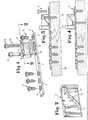
- Fig. 1 schaubildlich eine Druckplatte mit dem zusätzlich zu ihrer Festlegung und Verspannung dienenden Hilfsmittel, in
- Fig. 2 in größerem Maßstab einen Schnitt durch den Spannblock gemäß der Linie 2 - 2 in Fig. 1, in
- Fig. 3 in einer Schnittdarstellung die Anordnung des Spannblockes vor Kompression der beiden Knochenfragmente, in
- Fig. 4 die Anordnung des Spannblockes nach der durchgeführten Kompression und der Festlegung der Druckplatte, in
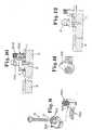
- Fig. 5 eine abgeänderte Ausführungsform der Erfindung, wobei der Spannblock an der Druckplatte festgeschraubt wird, in
- Fig. 6 die Einrichtung gemäß Fig. 5 in der auf der Druckplatte festgelegten Stellung, in
- Fig. 7 in einer auseinandergezogenen Darstellungsweise eine abgeänderte Ausführungsform, bei der die druckerzeugende Vorrichtung durch zwei miteinander zusammenwirkende schiefe Ebenen gebildet wird, in
- Fig. 8 , die Einrichtung gemäß Fig. 7 im eingebauten Zustand, in
- Fig. 9 in einer auseinandergezogenen Darstellungsweise eine abgeänderte Ausführungsform der druckerzeugenden Vorrichtung, wobei in diesem Fall die schiefe Ebene horizontal ausgerichtet ist, in
- Fig. 10 die Einrichtung gemäß Fig. 9 im eingebauten Zustand, in
- Fig. i1 die Einrichtung gemäß Fig. 9 in einer wirksamen Druckstellung und in
- Fig. 12 die zur Wirkstellung gemäß Fig. 11 zugehörige Stellung der beiden Knochenfragmente.
- Fig. 1 graphically a pressure plate with the auxiliary to its fixing and bracing tool, in
- Fig. 2 on a larger scale a section through the clamping block along the line 2 - 2 in Fig. 1, in
- Fig. 3 is a sectional view of the arrangement of the clamping block before compression of the two bone fragments, in
- F ig. 4 the arrangement of the clamping block after the compression and the fixing of the pressure plate, in
- Fig. 5 shows a modified embodiment of the invention, wherein the clamping block is screwed onto the pressure plate, in
- FIG. 6 shows the device according to FIG. 5 in the position fixed on the pressure plate, in
- Fig. 7 in an exploded view a modified embodiment, in which the pressure generating device is formed by two interacting inclined planes, in
- Fig. 8, the device of FIG. 7 in the installed state, in
- Fig. 9 in an exploded view a modified embodiment of the pressure generating device, in which case the inclined plane is aligned horizontally, in
- Fig. 10 the device of FIG. 9 in the installed state, in
- Fig. I1 the device of FIG. 9 in an effective pressure position and in
- FIG. 12 shows the position of the two bone fragments associated with the active position according to FIG. 11.
In der nachfolgenden Figurenbeschreibung sind so weit wie möglich gleiche Teile mit gleichen Bezugszeichen versehen und nur die unterschiedlich ausgebildeten Teile mit abgeänderten Bezugszeichen benannt.In the following description of the figures, the same parts are provided with the same reference numerals as far as possible and only the differently designed parts are designated with modified reference numerals.
In den Zeichnungen ist mit 1 eine Druckplatte bezeichnet, die eine sogenannte Fixationsseite 2 und eine Spannseite 3 aufweist. In der Fixationsseite sind bei dem dargestellten Ausführungsbeispiel drei Löcher 4 vorgesehen, die der Aufnahme von Befestigungsschrauben 5 handelsüblicher Art dienen.In the drawings, 1 denotes a pressure plate, which has a so-called
In der Spannseite 3 ist in der Druckplatte 1 ein Langloch 6 vorgesehen, über das gemäß Fig. 1 ein Spannblock 7 gesetzt werden kann, der an der Druckplatte 1 mittels einer Schraube 8 festlegbar ist. Die Schraube 8 weist zu diesem Zweck einen Gewindebereich 9 auf, der mit dem Innengewinde einer Bohrung 1o in der Druckplatte 1 kämmt. Die Schraube führt sich in einer Bohrung 11 im Spannblock 7, so daß ein bewegungsfreies Festlegen des Spannblockes 7 möglich ist.In the
Innerhalb des Spannblockes 7 ist ein ovales Schraubenloch 12 (Fig. 2) vorgesehen, das eine ovale Randneigung 14 mit etwa 45o Neigung besitzt. Mit dieser Randneigung 14 des Schraubenloches arbeitet eine als Knochenschraube ausgebildete Spannschraube 15 zusammen, die einen entsprechenden an sich bekannten Schraubenkopf 16 mit konischer Geometrie aufweist.Within the holding block 7 an oval screw hole 12 (Fig. 2) is provided which has an oval edge inclination 14 of about 45° inclination. With this edge inclination 14 of the screw hole, a
Zusätzlich sind auf der Spannseite der Druckplatte 1 weitere Befestigungslöcher vorgesehen, wobei in Fig. 1 das Befestigungsloch 17 erkennbar ist. Mit diesem Befestigungsloch 17 kann eine Befestigungsschraube 5 zusammenwirken, wie dies später noch zu erläutern ist. In den Zeichnungen sind mit 18 und 19 zwei Knochenfragmente bezeichnet, die im Bereich bei 2o gebrochen sind und in einem Abstand voneinander stehen, wobei dieser Bereich 2o durch die eigentliche Druckplatte wieder zusammengeführt werden soll.In addition, further fastening holes are provided on the clamping side of the pressure plate 1, the
Die Arbeitsweise mit der erfindungsgemäßen Vorrichtung ist wie folgt:
- Der Spannblock 7 wird unter Zuhilfenahme der Schraube 8 auf der Oberseite der Druckplatte 1 derart festgelegt, daß die Öffnung des Schraubloches 12 sich oberhalb eines Langloches 6 befindet. Nunmehr wird, wie dies Fig. 3 verdeutlicht, die
Spannschraube 15 in den Spannblock 7 eingesetzt und durch Drehen dieser Spannschraube 15 wirdnunmehr das Knochenfragment 19auf das Fragment 18 unter erheblicher Kompressionsspannung zubewegt.
- The clamping block 7 is fixed with the aid of the
screw 8 on the top of the pressure plate 1 such that the opening of the screw hole 12 is above anelongated hole 6. Now, as shown in FIG. 3, the clampingscrew 15 is inserted into the clamping block 7 and by rotating this clampingscrew 15, thebone fragment 19 is now moved towards thefragment 18 under considerable compression tension.
Hat das Fragment 19 die in Fig. 4 dargestellte Stellung erreicht, wird diese Stellung durch Einschrauben der Befestigungsschraube 5 in das Befestigungsloch 17 festgelegt. Nunmehr kann die Spannschraube 15 aus dem Spannblock 7 entfernt und der Spannblock 7 durch Lösen der Schraube 8 von der Druckplatte 1 freigegeben werden.If the
Es ist möglich, daß mehrere Löcher 1o und 6 in der Druckplatte 1 vorgesehen werden, um somit ein Versetzen des Spannblockes zu ermöglichen, dann, wenn der durch die Größe des Schraubloches 12 erzielte Spannweg nicht ausreichend sein sollte.It is possible for a plurality of
Bei der Ausführungsform gemäß Fig. 5 und 6 ist innerhalb eines Spannblockes 7o ein Schraubloch 12 vorgesehen, das eine ovale Randneigung von etwa 45° entsprechend der Ausführungsform gemäß Fig. 2 aufweist. Mit der Randneigung des Schraubloches 12 arbeitet eine Spannmutter 4o zusammen, die eine entsprechende an sich bekannte konische Geometrie 41 aufweist.In the embodiment according to FIGS. 5 and 6, a screw hole 12 is provided within a clamping block 7o, which has an oval edge inclination of approximately 45 ° in accordance with the embodiment according to FIG. 2. A clamping nut 4o, which has a corresponding
Der Spannblock weist eine Aufnahmeöffnung 21 auf, die eine Knochenschraube 22 aufnimmt und die durch das Langloch 6 greift und sich in den Knochen 19 einschraubt. Fig. 6 zeigt, daß die Knochenschraube 22 auf einem großen Teil ihrer Länge innerhalb der Aufnahmeöffnung 21 geführt und gehalten ist.The clamping block has a receiving
Eine Schraube 43 weist ein Außengewinde 44 auf, das nach oben durch eine Widerlagerscheibe 45 begrenzt wird, die sich bei eingeschraubtem Gewinde 44 in die Bohrung 1o auf der Oberseite der Druckplatte 1 auflegt. Im oberen Bereich der Schraube 43 ist ein weiteres Gewinde vorgesehen, das mit dem Innengewinde der Spannmutter 4o kämmt, so daß die Spannmutter 4o auf der Schraube 43 nach unten bewegt werden kann. Hierbei kommt die Spannmutter 4o mit der konischen Geometrie 41 zur Anlage an der schiefen Ebene in dem Schraubloch 12.A screw 43 has an external thread 44 which is delimited at the top by an abutment disk 45 which, when the thread 44 is screwed in, fits into the
Zwischen der Oberseite der Druckplatte 1 und der Unterseite des Spannblockes 7o befindet sich eine Zwischenlage 24, auf der sich der Spannblock 7o ohne Berührung mit der Druckplatte 1 bei seiner Verschiebebewegung bewegen kann.Between the top of the pressure plate 1 and the bottom of the clamping block 7o there is an
Die Wirkungsweise dieser Einrichtung ist wie folgt:
- Der Spannblock 7o wird über die Schraube 43 unter Zwischenschaltung der Zwischenlage 24 auf der Oberseite der Druckplatte 1 oberhalb des Langloches 6 festgelegt. Anschließend wird die
Knochenschraube 22 durch die Aufnahmeöffnung 21 hindurchgeführt und inden Knochenteil 19 eingeschraubt. Dabei befindet sich dieKnochenschraube 22 an dem äußeren rechten Rand desLangloches 6. Durch Aufschrauben der Spannmutter 4o auf das obere Teil des Gewindes der Schraube 43 schraubt sich die Spannmutter 4o in Verbindung mit der im Schraubenloch 12 vorgesehenen schiefen Ebene nach unten und drückt dabei den Spannblock 7o und somitdas Knochenfragment 19 in der Zeichnung gemäß Fig. 5 nach links. Dadurch werden dieKnochenfragmente 18 und 19 aufeinanderzubewegt, ohne daß die für diese Schubbewegung erforderliche Kraftaus dem Knochenteil 19 aufgenommen werden muß, sondern dieSchraube 22 hat lediglich die Aufgabe, den Knochen zu schieben.
- The clamping block 7o is fixed via the screw 43 with the interposition of the
intermediate layer 24 on the upper side of the pressure plate 1 above theelongated hole 6. Thebone screw 22 is then passed through the receivingopening 21 and screwed into thebone part 19. Thebone screw 22 is located on the outer right edge of theelongated hole 6. By screwing the clamping nut 4o onto the upper part of the thread of the screw 43, the clamping nut 4o unscrews in connection with the inclined plane provided in the screw hole 12 and presses it down Clamping block 7o and thus thebone fragment 19 in the drawing according to FIG. 5 to the left. As a result, the bone fragments 18 and 19 are moved towards one another without the force required for this pushing movement having to be absorbed from thebone part 19, but thescrew 22 merely has the task of pushing the bone.
Bei der Ausführungsform gemäß den Fig. 7 und 8 ist eine Zwischenlage,24 vorgesehen. Der eigentliche Spänn- block7oo weist eine schiefe Ebene 152a auf, die mit einer schiefen Ebene 153a eines Bauteiles 15oa zusammenwirkt. In der Bohrung 1o der Druckplatte 1 wird eine Schraube 8o unter Zuhilfenahme des Gewindes 9o festgelegt, wobei sich auf diese Schraube 8o die Mutter 151a aufschraubt. In dem Spannblock 7o ist die Aufnahmeöffnung 21 vorgesehen, die der Aufnahme der Knochenschraube 22 dient. Bei dieser Ausführungsform erfolgt das Aufbringen des erforderlichen Spanndruckes in der schon anhand der Fig. 5 und 6 erläuterten Weise.In the embodiment according to FIGS. 7 and 8, an
Bei der in den Fig. 9 bis 12 dargestellten Ausführungsform wird zum Aufbringen des erforderlichen Spanndruckes eine schiefe Ebene benutzt, die horizontal ausgerichtet ist, d.h. es wird eine spiralige Scheibe 15oo vorgeschlagen. Die spiralige Scheibe 15oo ist an einem Spannblock 7ooo festgelegt, der über eine Schraube 8000 an der Druckplatte 1 befestigt ist. Der Spannblock 7000 weist eine Schulter 7001 auf, die die spiralige Scheibe 15oo übergreift. Durch die spiralige Scheibe 15oo führt die die Knochenschraube 22 aufnehmende Aufnahmeöffnung 21 und das Aufbringen des erforderlichen Druckes erfolgt durch Drehen der spiraligen Scheibe 15oo unter Zuhilfenahme eines entsprechenden Mutterkopfes 7010. Auch bei dieser Ausführungsform erfolgt die Spannbewegung entsprechend der anhand der Fig. 5 und 6 erläuterten Weise.In the embodiment shown in FIGS. 9 to 12, an inclined plane which is oriented horizontally is used to apply the required clamping pressure, ie a
Claims (14)
Translated fromGermanPriority Applications (1)
| Application Number | Priority Date | Filing Date | Title |
|---|---|---|---|
| AT80100776TATE1690T1 (en) | 1979-03-23 | 1980-02-15 | CLAMPING DEVICE FOR A PRESSURE PLATE FOR PERFORMING COMPRESSION OSTEOSYNTHESIS. |
Applications Claiming Priority (4)
| Application Number | Priority Date | Filing Date | Title |
|---|---|---|---|
| DE2911386ADE2911386C2 (en) | 1979-03-23 | 1979-03-23 | Clamping device for a pressure plate for performing a pressure osteosynthesis |
| DE2911386 | 1979-03-23 | ||
| DE2938202 | 1979-09-21 | ||
| DE19792938202DE2938202C2 (en) | 1979-09-21 | 1979-09-21 | Clamping device for a pressure plate for performing pressure osteosynthesis |
Publications (2)
| Publication Number | Publication Date |
|---|---|
| EP0016338A1true EP0016338A1 (en) | 1980-10-01 |
| EP0016338B1 EP0016338B1 (en) | 1982-10-27 |
Family
ID=25778351
Family Applications (1)
| Application Number | Title | Priority Date | Filing Date |
|---|---|---|---|
| EP80100776AExpiredEP0016338B1 (en) | 1979-03-23 | 1980-02-15 | Tensioning device for a compression plate for use in joining bone fragments under pressure |
Country Status (2)
| Country | Link |
|---|---|
| EP (1) | EP0016338B1 (en) |
| DE (1) | DE3060985D1 (en) |
Cited By (10)
| Publication number | Priority date | Publication date | Assignee | Title |
|---|---|---|---|---|
| US4493317A (en)* | 1980-11-20 | 1985-01-15 | Synthes Ltd. (U.S.A.) | Surgical compression plate and drill guide |
| EP0263938A3 (en)* | 1986-08-19 | 1988-07-06 | Christian Krenkel | Pulling nail for osteosynthesis |
| US6533786B1 (en) | 1999-10-13 | 2003-03-18 | Sdgi Holdings, Inc. | Anterior cervical plating system |
| US6692503B2 (en) | 1999-10-13 | 2004-02-17 | Sdgi Holdings, Inc | System and method for securing a plate to the spinal column |
| EP2223665A1 (en) | 2009-02-23 | 2010-09-01 | Zrinski AG | Implant for fusing bones or bone sections, in particular of the carpus area of a wrist |
| US8016864B2 (en) | 1998-04-30 | 2011-09-13 | Warsaw Orthopedic, Inc. | Anterior implant for the spine |
| US8506607B2 (en) | 2006-12-19 | 2013-08-13 | Zrinski Ag | Orthopedic screw fastener system |
| US9855082B2 (en) | 2009-05-12 | 2018-01-02 | DePuy Synthes Products, Inc. | Readjustable locking plate hole |
| JP2020096835A (en)* | 2018-12-17 | 2020-06-25 | ネクストレミティ ソルーションズ インコーポレイテッドNextremity Solutions, Inc. | Compression force magnifier |
| US10869702B2 (en) | 2017-05-12 | 2020-12-22 | Nextremity Solutions, Inc. | Compression force magnifier |
Citations (7)
| Publication number | Priority date | Publication date | Assignee | Title |
|---|---|---|---|---|
| US3386437A (en)* | 1966-01-14 | 1968-06-04 | Richard Mfg Company | Compression device for use with a bone fracture plate |
| US3528085A (en)* | 1968-03-22 | 1970-09-08 | Walker Reynolds Jr | Bone compression plate |
| US3534731A (en)* | 1967-08-18 | 1970-10-20 | Jean Nicolas Muller | Means for joining parts of fractured bones |
| DE1791228B1 (en)* | 1966-06-22 | 1971-12-30 | Synthes Ag | Osteosynthetic pressure plate |
| FR2210908A6 (en)* | 1972-12-15 | 1974-07-12 | Emco Sa | |
| FR2289153A1 (en)* | 1974-10-31 | 1976-05-28 | Tornier Rene | Appts. for osteosynthesis tensioning - has compression unit engaging splint and bone portion to force bone portions together |
| DE2802090A1 (en)* | 1977-01-31 | 1978-08-03 | Antonio Blas Vernet | COMPRESSION / DISTRACTION DEVICE FOR OSTEOSYNTHESIS |
- 1980
- 1980-02-15EPEP80100776Apatent/EP0016338B1/ennot_activeExpired
- 1980-02-15DEDE8080100776Tpatent/DE3060985D1/ennot_activeExpired
Patent Citations (7)
| Publication number | Priority date | Publication date | Assignee | Title |
|---|---|---|---|---|
| US3386437A (en)* | 1966-01-14 | 1968-06-04 | Richard Mfg Company | Compression device for use with a bone fracture plate |
| DE1791228B1 (en)* | 1966-06-22 | 1971-12-30 | Synthes Ag | Osteosynthetic pressure plate |
| US3534731A (en)* | 1967-08-18 | 1970-10-20 | Jean Nicolas Muller | Means for joining parts of fractured bones |
| US3528085A (en)* | 1968-03-22 | 1970-09-08 | Walker Reynolds Jr | Bone compression plate |
| FR2210908A6 (en)* | 1972-12-15 | 1974-07-12 | Emco Sa | |
| FR2289153A1 (en)* | 1974-10-31 | 1976-05-28 | Tornier Rene | Appts. for osteosynthesis tensioning - has compression unit engaging splint and bone portion to force bone portions together |
| DE2802090A1 (en)* | 1977-01-31 | 1978-08-03 | Antonio Blas Vernet | COMPRESSION / DISTRACTION DEVICE FOR OSTEOSYNTHESIS |
Cited By (19)
| Publication number | Priority date | Publication date | Assignee | Title |
|---|---|---|---|---|
| US4493317A (en)* | 1980-11-20 | 1985-01-15 | Synthes Ltd. (U.S.A.) | Surgical compression plate and drill guide |
| EP0263938A3 (en)* | 1986-08-19 | 1988-07-06 | Christian Krenkel | Pulling nail for osteosynthesis |
| US8016864B2 (en) | 1998-04-30 | 2011-09-13 | Warsaw Orthopedic, Inc. | Anterior implant for the spine |
| US6533786B1 (en) | 1999-10-13 | 2003-03-18 | Sdgi Holdings, Inc. | Anterior cervical plating system |
| US6692503B2 (en) | 1999-10-13 | 2004-02-17 | Sdgi Holdings, Inc | System and method for securing a plate to the spinal column |
| US8167919B2 (en) | 1999-10-13 | 2012-05-01 | Warsaw Orthopedic, Inc. | System and method for securing a plate to the spinal column |
| US8506607B2 (en) | 2006-12-19 | 2013-08-13 | Zrinski Ag | Orthopedic screw fastener system |
| EP2223665A1 (en) | 2009-02-23 | 2010-09-01 | Zrinski AG | Implant for fusing bones or bone sections, in particular of the carpus area of a wrist |
| US9855082B2 (en) | 2009-05-12 | 2018-01-02 | DePuy Synthes Products, Inc. | Readjustable locking plate hole |
| US10799275B2 (en) | 2009-05-12 | 2020-10-13 | DePuy Synthes Products, Inc. | Readjustable locking plate hole |
| US10869702B2 (en) | 2017-05-12 | 2020-12-22 | Nextremity Solutions, Inc. | Compression force magnifier |
| US11723701B2 (en) | 2017-05-12 | 2023-08-15 | Zimmer, Inc. | Compression force magnifier |
| USD1033648S1 (en) | 2017-05-12 | 2024-07-02 | Zimmer, Inc. | Compression force magnifier |
| JP2020096835A (en)* | 2018-12-17 | 2020-06-25 | ネクストレミティ ソルーションズ インコーポレイテッドNextremity Solutions, Inc. | Compression force magnifier |
| GB2582408A (en)* | 2018-12-17 | 2020-09-23 | Nextremity Solutions Inc | Compression force magnifier |
| GB2590571A (en)* | 2018-12-17 | 2021-06-30 | Nextremity Solutions Inc | Compression force magnifier |
| US11202664B2 (en) | 2018-12-17 | 2021-12-21 | Nextremity Solutions, Inc. | Compression force magnifier |
| GB2582408B (en)* | 2018-12-17 | 2023-02-01 | Zimmer Inc | Compression force magnifier |
| GB2590571B (en)* | 2018-12-17 | 2023-02-01 | Zimmer Inc | Compression force magnifier |
Also Published As
| Publication number | Publication date |
|---|---|
| EP0016338B1 (en) | 1982-10-27 |
| DE3060985D1 (en) | 1982-12-02 |
Similar Documents
| Publication | Publication Date | Title |
|---|---|---|
| DE1566153B1 (en) | Osteosynthetic pressure plate | |
| EP0487830A1 (en) | Implant for correction of the humain spinal column | |
| AT406657B (en) | DEVICE FOR CLAMPING A CHIP KNIFE | |
| EP0016338A1 (en) | Tensioning device for a compression plate for use in joining bone fragments under pressure | |
| EP1155782B1 (en) | Support device with a carrier head for holding a workpiece | |
| DE2815826A1 (en) | CLAMPING DEVICE FOR FASTENING A RAIL | |
| EP0094537A1 (en) | Single and multiple cutting-off tool | |
| DE3022440C2 (en) | Multi-part base plate for furniture hinges | |
| DE20202615U1 (en) | Template for guiding a surgical processing tool | |
| DE68917889T2 (en) | Attachment for rails. | |
| DE4007937A1 (en) | Resilient rail for rail vehicles - has relatively adjustable frame side walls drawn together by bolts against resilient | |
| DE2938202C2 (en) | Clamping device for a pressure plate for performing pressure osteosynthesis | |
| DE2653302A1 (en) | End mill with disposable insert - having cutting edges projecting from one end and centring recess in one major face | |
| EP1065339B1 (en) | Fastening device for hinge flaps | |
| DE2911386C2 (en) | Clamping device for a pressure plate for performing a pressure osteosynthesis | |
| DE4213770C1 (en) | Device for positioning a tool or workpiece on a machine tool | |
| CH692010A5 (en) | Device for clamping and alignment of tool or workpiece in relation to reference base has upper part for clamping the tool or workpiece, lower part for fixture to reference base and devices for connecting upper and lower parts | |
| DE3732023A1 (en) | Device for the adjustable fastening of a hinge strap (door, window) to a steel frame | |
| DE3211153A1 (en) | Device for adjustment and fixing of the plane of section in bone cuts | |
| DE8203368U1 (en) | Holding and connecting part for vibration or impact devices, in particular for hydraulic hammers for articulated boom machines | |
| DE29818831U1 (en) | Osteosynthetic retention system | |
| DE19745326A1 (en) | Bed plate for rail fastening on permanent way or sleeper | |
| DE3637485C2 (en) | ||
| DE19828211A1 (en) | Work-clamping jaw for machine-tool table | |
| EP0771715B1 (en) | Combination printer and cutting device for webs of flat material |
Legal Events
| Date | Code | Title | Description |
|---|---|---|---|
| PUAI | Public reference made under article 153(3) epc to a published international application that has entered the european phase | Free format text:ORIGINAL CODE: 0009012 | |
| AK | Designated contracting states | Designated state(s):AT BE CH DE FR GB IT NL SE | |
| 17P | Request for examination filed | ||
| ITF | It: translation for a ep patent filed | ||
| GRAA | (expected) grant | Free format text:ORIGINAL CODE: 0009210 | |
| AK | Designated contracting states | Designated state(s):AT BE CH DE FR GB IT NL SE | |
| REF | Corresponds to: | Ref document number:1690 Country of ref document:AT Date of ref document:19821115 Kind code of ref document:T | |
| REF | Corresponds to: | Ref document number:3060985 Country of ref document:DE Date of ref document:19821202 | |
| PGFP | Annual fee paid to national office [announced via postgrant information from national office to epo] | Ref country code:FR Payment date:19840130 Year of fee payment:5 | |
| PGFP | Annual fee paid to national office [announced via postgrant information from national office to epo] | Ref country code:CH Payment date:19840214 Year of fee payment:5 | |
| PGFP | Annual fee paid to national office [announced via postgrant information from national office to epo] | Ref country code:BE Payment date:19840331 Year of fee payment:5 | |
| PGFP | Annual fee paid to national office [announced via postgrant information from national office to epo] | Ref country code:SE Payment date:19841231 Year of fee payment:6 | |
| PGFP | Annual fee paid to national office [announced via postgrant information from national office to epo] | Ref country code:AT Payment date:19870211 Year of fee payment:8 | |
| PGFP | Annual fee paid to national office [announced via postgrant information from national office to epo] | Ref country code:NL Payment date:19870228 Year of fee payment:8 | |
| PG25 | Lapsed in a contracting state [announced via postgrant information from national office to epo] | Ref country code:AT Effective date:19880215 | |
| PG25 | Lapsed in a contracting state [announced via postgrant information from national office to epo] | Ref country code:SE Effective date:19880216 | |
| BERE | Be: lapsed | Owner name:BRINCKMANN PAUL Effective date:19880228 | |
| PG25 | Lapsed in a contracting state [announced via postgrant information from national office to epo] | Ref country code:NL Effective date:19880901 | |
| NLV4 | Nl: lapsed or anulled due to non-payment of the annual fee | ||
| PG25 | Lapsed in a contracting state [announced via postgrant information from national office to epo] | Ref country code:FR Free format text:LAPSE BECAUSE OF NON-PAYMENT OF DUE FEES Effective date:19881028 | |
| GBPC | Gb: european patent ceased through non-payment of renewal fee | ||
| PG25 | Lapsed in a contracting state [announced via postgrant information from national office to epo] | Ref country code:GB Free format text:LAPSE BECAUSE OF NON-PAYMENT OF DUE FEES Effective date:19881118 | |
| REG | Reference to a national code | Ref country code:FR Ref legal event code:ST | |
| PG25 | Lapsed in a contracting state [announced via postgrant information from national office to epo] | Ref country code:CH Effective date:19890228 Ref country code:BE Effective date:19890228 | |
| PGFP | Annual fee paid to national office [announced via postgrant information from national office to epo] | Ref country code:DE Payment date:19890526 Year of fee payment:10 | |
| REG | Reference to a national code | Ref country code:CH Ref legal event code:PL | |
| PG25 | Lapsed in a contracting state [announced via postgrant information from national office to epo] | Ref country code:DE Effective date:19901101 | |
| EUG | Se: european patent has lapsed | Ref document number:80100776.6 Effective date:19880927 | |
| PLBE | No opposition filed within time limit | Free format text:ORIGINAL CODE: 0009261 | |
| STAA | Information on the status of an ep patent application or granted ep patent | Free format text:STATUS: NO OPPOSITION FILED WITHIN TIME LIMIT |