EP0015607B1 - Monochromator - Google Patents
MonochromatorDownload PDFInfo
- Publication number
- EP0015607B1 EP0015607B1EP80200149AEP80200149AEP0015607B1EP 0015607 B1EP0015607 B1EP 0015607B1EP 80200149 AEP80200149 AEP 80200149AEP 80200149 AEP80200149 AEP 80200149AEP 0015607 B1EP0015607 B1EP 0015607B1
- Authority
- EP
- European Patent Office
- Prior art keywords
- monochromator
- diffraction grating
- mirror
- concave spherical
- optical axis
- Prior art date
- Legal status (The legal status is an assumption and is not a legal conclusion. Google has not performed a legal analysis and makes no representation as to the accuracy of the status listed.)
- Expired
Links
- 230000003287optical effectEffects0.000claimsdescription38
- 230000001419dependent effectEffects0.000claimsdescription6
- 230000005855radiationEffects0.000description26
- 238000010276constructionMethods0.000description5
- 239000002131composite materialSubstances0.000description3
- 238000005259measurementMethods0.000description3
- 230000009977dual effectEffects0.000description2
- 238000002834transmittanceMethods0.000description2
- 230000004075alterationEffects0.000description1
- 230000005670electromagnetic radiationEffects0.000description1
- 238000010348incorporationMethods0.000description1
- 239000012925reference materialSubstances0.000description1
- 230000003595spectral effectEffects0.000description1
- 238000001228spectrumMethods0.000description1
Images


Classifications
- G—PHYSICS
- G01—MEASURING; TESTING
- G01J—MEASUREMENT OF INTENSITY, VELOCITY, SPECTRAL CONTENT, POLARISATION, PHASE OR PULSE CHARACTERISTICS OF INFRARED, VISIBLE OR ULTRAVIOLET LIGHT; COLORIMETRY; RADIATION PYROMETRY
- G01J3/00—Spectrometry; Spectrophotometry; Monochromators; Measuring colours
- G01J3/12—Generating the spectrum; Monochromators
- G01J3/18—Generating the spectrum; Monochromators using diffraction elements, e.g. grating
Definitions
- the present inventionrelates to monochromators. -
- a monochromatoris an optical device for. deriving monochromatic light from polychromatic light, the expression "light” being used in this context to mean electro-magnetic radiation in the ultra-violet, visible and infra-red bands.
- the monochromator described by Fastieincludes a collimating concave spherical mirror and a plane diffraction grating mounted for rotation about an axis parallel to the grooves on the face of the grating and perpendicular to the central optical axis of the spherical mirror.
- the gratingis positioned on the central optical axis adjacent the entrance and exit slits of the monochromator, which lie in the focal plane of the mirror and also lie upon the circumference of a circle having as its centre the central optical axis of the spherical mirror.
- the positioning of the plane diffraction grating upon the central optical axis of the spherical mirror adjacent the slitshas proved a constraint upon the mechanical design of the associated spectrophotometer and, in particular, of the mechanical wavelength drive system as in a complex instrument it may be necessary to provide a wavelength-related drive to vary the width of entrance and exit slits, to position radiation filters and, commonly in infra-red instruments, to index a rotating turret carrying two or more diffraction gratings.
- an Ebert monochromatorcomprises a concave spherical mirror, means defining first and second slits which lie in a common plane perpendicular to the central optical axis of the concave spherical mirror, and a diffraction grating pivotable about an axis parallel to the grooves on it, in which a beam of light entering the first slit is collimated by the concave spherical mirror and directed onto the diffraction grating and in which the dispersed beam of light from the diffraction grating is reflected from the concave spherical mirror towards the second slit, characterised in that the axis about which the diffraction grating is pivotable is disposed parallel to the central optical axis of the concave spherical mirror, and a plane mirror is provided in the optical path between the spherical concave mirror and the diffraction grating wherein the plane mirror is positioned relative to the
- the monochromatormay include at least one further diffraction grating pivotable about an axis parallel with the grooves on it and parallel to the central optical axis of the concave spherical mirror with the plane mirror pivotable to include either the diffraction grating or the further diffraction grating in the optical path of the monochromator whereby an extended wavelength range may be covered.
- a monochromator according to the invention having more than one diffraction gratingmay have the diffraction gratings driven from a common cam-shaft forming part of a wavelength drive mechanism with the common cam- shaft arranged parallel to the central optical axis of the concave spherical mirror for simplicity of construction.
- the monochromatormay further comprise a filter-holder movable to introduce a selected one of a plurality of filters mounted thereon into the beam of light entering the monochromator, the filter-holder also being mechanically driven from the common cam- shaft whereby the filters may be introduced in a wavelength dependent manner.
- a monochromator according to the inventionmay be constructed such that the slit defining means is a common lamina in which the slits are apertures, with the lamina mounted for movement along the central optical axis of the concave spherical mirror, to enable the slits to be precisely located in the focal plane of the concave spherical mirror.
- the laminamay be a disc in which the slits are apertures rotatable about the central optical axis of the concave spherical mirror, whereby to vary slit width in accordance with monochromator wavelength.
- the rotatable laminamay also be driven from the common cam-shaft.
- the monochromatorcomprises an entrance slit 11 formed in a slit plate 12; a plano-concave spherical collimator mirror 13 with a reflective surface 14; a plans mirror 15, with a reflective surface 16, mounted upon the central optical axis 17 of mirror 13 and inclined to it; a plane diffraction grating 18 mounted for rotation about an axis 19 parallel to the grooves upon the active face 20 of the grating and parallel to the central optical axis 17 of mirror 13; and an exit slit 21 formed in a slit plate 22.
- Slit plates 12 and 22lie in, or in a plane closely adjacent the parallel to, the focal plane of mirror 13 and slits 11 and 21 are disposed about the circumference of a circle centered upon the central optical axis 17 of mirror 13, the so- called Ebert circle.
- a beam of light brought to a focus in slit 11is collimated by mirror 13, reflected from mirror 15 and falls upon the active face 20 of plane diffraction grating 18.
- the dispersed beam from the diffraction grating 18falls upon mirror 15 and is reflected on to mirror 13 and brought to a focus in the plane of exit slit 21.
- the line 23is the optical centre line of the beam of light from entrance slit 11 to exit slit 21.
- plane diffraction grating 18is disposed with axis 19 parallel to central optical axis 17 of concave spherical mirror 13 and vertically above it.
- the plane mirror 15is thus positioned relative to the central optical axis 17 and to concave spherical mirror 13 such as to ensure that the plane defined by the optical centre line 23A of the collimated beam from mirror 13 and the optical centre line 23B of the dispersed beam from grating 18 intersects the grooves of grating 18 at right angles.
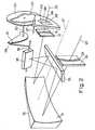
- FIG 2is a perspective view of the Ebert monochromator described in relation to Figure 1, with the addition of certain mechanical wavelength drive components to illustrate the simpler mechanical construction made possible by a monochromator constructed according to the present invention. Integers already described bear the same reference numerals.
- a camshaft 30 disposed parallel with the central optical axis 17 of mirror 13is driven by, for example, a stepping motor (not shown) and carries a cam 31 and a disc 32 having a camslot 33 in one face.
- a cam-follower 34 attached to a grating pivot 19follows the camming surface of cam 31 and a pin (not shown) carried upon the rear face of a filter holder 36 pivotably mounted upon a shaft 37, engages in and follows the cam slot 33 in disc 32.
- Filter holder 36carries three radiation filters 38, 39 and 40 which are positioned in the incoming beam of light to the monochromator in a series of wavelength dependent steps to prevent unwanted higher wavelength orders of light from grating 18 appearing at exit slit 21.
- camshaft 30Rotation of camshaft 30 causes grating 18 to rotate scanning the dispersed light beam across exit slit 21.
- Disc 32is positioned upon cam-shaft 30 such that radiation filters 38, 39 and 40 are introduced into incoming light beam in sequence corresponding with predetermined wavelength ranges of the emergent beam from exit slit 21.
- camsmay be mounted upon cam- shaft 30 to drive other wavelength-dependent elements in a monochromator according to the invention.
- a slit plate 41has extended slits 42 and 43 formed in it, disposed about the circumference of the Ebert circle of the associated monochromator.
- the plate 41is mounted for rotation upon a shaft 44 axially aligned with the central optical axis 17 of the associated monochromator.
- Cam follower 45 attached to slit plate 41follows the periphery of cam 46 secured to common camshaft 30 of the monochromator described in relation to Figure 2, causing slit plate 41 to rotate upon shaft 44, to provide the correct width of slit in the incoming and outgoing beams at any wavelength.
- a further diffraction grating or gratingscould be provided each pivotable on an axis parallel to that of grating 18 and rotated by means of a cam carried by camshaft 30.
- the grating camswould be arranged upon cam- shaft 30 to permit each grating to disperse a specific waveband and for the wavebands to be successive.
- Beam directing meanssuch as, for example, a pivoted plane mirror could also be driven from the same cam shaft 30 to direct collimated radiation from mirror 13 to each diffraction grating in turn.
- the overall dimensions of the mirror 13were 120 mm by 60 mm.
- the diffraction gratingshad overall dimensions of 50 mm by 50 mm, of which an active area of 45 mmx45 mm was used.
- the plane beam directing mirrorwas surface aluminised, and had dimensions of 70 mm by 60 mm.
- the entrance and exit slits of the monochromatorwere formed in a rotating slit plate, were centred upon the circumference of a circle of 37.5 mm radius and increased in width exponentially along their length to give a constant change of beam energy for a given angular rotation of the slit plate, at any point along their lengths.
- Figure 4is a diagrammatic illustration of a dual beam spectrophotometer incorporating a monochromator according to the invention.
- the spectrophotometer shown in Figure 4comprises a source of radiation 100, means for forming two beams of radiation, means for combining the two beams, a monochromator 101 in accordance with the present invention and such as has been described with reference to Figures 1 to 3, a detector 102 and signal processing means 103.
- Radiation from source 100is reflected by a mirror 104 along the path 105 which passes through a sample cell 106 within a measurement compartment 107.
- the radiation following path 105is reflected by two further mirrors 108 and 109 onto a rotating sector mirror assembly 110 which alternately allows the radiation following the path 105 to fall on a mirror 111 or reflects it away from the mirror 111.
- Radiation from source 100is also reflected by a mirror 112 along a second path 113 which passes through a reference cell 114, which is also located in the measurement compartment 107.
- the radiation following path 113is reflected by two further mirrors 115 and 116 onto the rotating sector mirror assembly 110 which alternately reflects the radiation following the path 113 onto the mirror 111 or allows it to pass through and thus be directed away from the mirror 111.
- a composite beam 117which comprises pulses of radiation which have followed path 105 interlaced with pulses of radiation which have followed path 113 is formed.
- the rotating mirror 110has successive sectors which are radiation transparent, radiation absorbing, radiation reflective and radiation absorbing in series thus caused the composite beam 117 to comprise interlaced pulses of radiation which have followed paths 105 and 113 respectively separated by periods in which radiation from the source 100 is interrupted.
- the composite beam 117 of wideband radiationis reflected by mirror 111 on to the entrance slit of monochromator 101 which selects radiation of a narrow band of wavelengths from the wideband radiation presented to the entrance slit.
- the narrow band radiation emerging from the exit slit of monochromator 101is reflected onto a detector 102 by a mirror 118.
- the output of the detector 102is fed via signal processing means 103 to an indicator 119.
- Indicator 119is typically a chart recorder in which the chart is advanced in synchronism with the wavelength of the narrowband radiation emerging from the monochromator 101.
- other indicatorscould be used, for example video display units or the output of the signal processing means could be fed to a computer which could either store the information or drive a printer to produce a print out of transmittance against wavelength.
- the transmittance of a sampleIn order to determine the transmittance of a sample at one, or a series of wavelengths, it is inserted in the measurement compartment 107 so as to be traversed by the sample beam 105 and the signal processing means 103 arranged to determine the ratio of the magnitudes of the radiation emerging from the sample cell 106 to that emerging from the reference cell 114, containing a reference material.
Landscapes
- Physics & Mathematics (AREA)
- Spectroscopy & Molecular Physics (AREA)
- General Physics & Mathematics (AREA)
- Spectrometry And Color Measurement (AREA)
Description
- The present invention relates to monochromators.-
- A monochromator is an optical device for. deriving monochromatic light from polychromatic light, the expression "light" being used in this context to mean electro-magnetic radiation in the ultra-violet, visible and infra-red bands.
- One form of monochromator adapted for use in spectrophotometric apparatus, since its redis- covery by Fastie in 1952, is the monochromator originally proposed by Ebert in 1889. The Ebert monochromator described by Fastie in the Journal of the Optical Society of America,
Volume 42, No. 9 (p. 641 et seq.), possesses good spectral resolution and minimal aberration in addition to being more simple, compact and mechanically stable than other commonly employed monochromators. - The monochromator described by Fastie includes a collimating concave spherical mirror and a plane diffraction grating mounted for rotation about an axis parallel to the grooves on the face of the grating and perpendicular to the central optical axis of the spherical mirror. The grating is positioned on the central optical axis adjacent the entrance and exit slits of the monochromator, which lie in the focal plane of the mirror and also lie upon the circumference of a circle having as its centre the central optical axis of the spherical mirror.
- The positioning of the plane diffraction grating upon the central optical axis of the spherical mirror adjacent the slits has proved a constraint upon the mechanical design of the associated spectrophotometer and, in particular, of the mechanical wavelength drive system as in a complex instrument it may be necessary to provide a wavelength-related drive to vary the width of entrance and exit slits, to position radiation filters and, commonly in infra-red instruments, to index a rotating turret carrying two or more diffraction gratings.
- It is an object of the present invention to provide a modified Ebert monochromator in which the diffraction grating is positioned off the central optical axis of the concave spherical mirror, thereby permitting advantageous mechanical constructions to be achieved.
- According to the present invention an Ebert monochromator comprises a concave spherical mirror, means defining first and second slits which lie in a common plane perpendicular to the central optical axis of the concave spherical mirror, and a diffraction grating pivotable about an axis parallel to the grooves on it, in which a beam of light entering the first slit is collimated by the concave spherical mirror and directed onto the diffraction grating and in which the dispersed beam of light from the diffraction grating is reflected from the concave spherical mirror towards the second slit, characterised in that the axis about which the diffraction grating is pivotable is disposed parallel to the central optical axis of the concave spherical mirror, and a plane mirror is provided in the optical path between the spherical concave mirror and the diffraction grating wherein the plane mirror is positioned relative to the spherical concave mirror and diffraction grating such that the plane containing both the optical centre line of the collimated beam incident upon the diffraction grating and the optical centre line of the beam dispersed by the diffraction grating intersects the diffraction grating at right angles to the grooves upon it. This results in a construction of Ebert monochromator in which the diffraction grating can be positioned optimally in relation to, for example, the elements of a wavelength drive system and away from the entrance and exit slits.
- The monochromator may include at least one further diffraction grating pivotable about an axis parallel with the grooves on it and parallel to the central optical axis of the concave spherical mirror with the plane mirror pivotable to include either the diffraction grating or the further diffraction grating in the optical path of the monochromator whereby an extended wavelength range may be covered.
- A monochromator according to the invention having more than one diffraction grating may have the diffraction gratings driven from a common cam-shaft forming part of a wavelength drive mechanism with the common cam- shaft arranged parallel to the central optical axis of the concave spherical mirror for simplicity of construction. The monochromator may further comprise a filter-holder movable to introduce a selected one of a plurality of filters mounted thereon into the beam of light entering the monochromator, the filter-holder also being mechanically driven from the common cam- shaft whereby the filters may be introduced in a wavelength dependent manner.
- A monochromator according to the invention may be constructed such that the slit defining means is a common lamina in which the slits are apertures, with the lamina mounted for movement along the central optical axis of the concave spherical mirror, to enable the slits to be precisely located in the focal plane of the concave spherical mirror. The lamina may be a disc in which the slits are apertures rotatable about the central optical axis of the concave spherical mirror, whereby to vary slit width in accordance with monochromator wavelength. The rotatable lamina may also be driven from the common cam-shaft.
- Preferred constructions of Ebert monochromator are illustrated in the accompanying drawings of which:
- Figure 1 shows a perspective view of an Ebert monochromator according to the invention,
- Figure 2 shows a perspective view of the Ebert monochromator of Figure 1 with the addition of certain wavelength drive components,
- Figure 3 shows a rotatable slit plate suitable for incorporation in the monochromator of Figure 2, and
- Figure 4 shows in diagrammatic form a dual beam spectrophotometer incorporating a monochromator according to the present invention.
- Figure 1 is a perspective view of an Ebert monochromator in accordance with the present invention.
- The monochromator comprises an
entrance slit 11 formed in aslit plate 12; a plano-concavespherical collimator mirror 13 with areflective surface 14; aplans mirror 15, with areflective surface 16, mounted upon the centraloptical axis 17 ofmirror 13 and inclined to it; a plane diffraction grating 18 mounted for rotation about anaxis 19 parallel to the grooves upon theactive face 20 of the grating and parallel to the centraloptical axis 17 ofmirror 13; and anexit slit 21 formed in aslit plate 22.Slit plates mirror 13 andslits optical axis 17 ofmirror 13, the so- called Ebert circle. - From a suitable source (not shown) a beam of light brought to a focus in
slit 11 is collimated bymirror 13, reflected frommirror 15 and falls upon theactive face 20 of plane diffraction grating 18. - The dispersed beam from the diffraction grating 18 falls upon
mirror 15 and is reflected on tomirror 13 and brought to a focus in the plane ofexit slit 21. Theline 23 is the optical centre line of the beam of light fromentrance slit 11 to exitslit 21. - As plane diffraction grating 18 is rotated about
axis 19 by drive means (not shown) between predetermined mechanical limits, the dispersed beam of light is scanned across the rear ofslit plate 21 and the wavelength of the beam of light emergent fromexit slit 21 is a function of the angular disposition of grating 18 to the collimated beam incident upon it. - In the monochromator illustrated in Figure 1,
plane diffraction grating 18 is disposed withaxis 19 parallel to centraloptical axis 17 of concavespherical mirror 13 and vertically above it. The plane mirror 15 inclined at 45° to the centraloptical axis 17, deflects the collimated beam frommirror 13 and the dispersed beam from grating 18 through 90°. Theplane mirror 15 is thus positioned relative to the centraloptical axis 17 and to concavespherical mirror 13 such as to ensure that the plane defined by theoptical centre line 23A of the collimated beam frommirror 13 and theoptical centre line 23B of the dispersed beam from grating 18 intersects the grooves of grating 18 at right angles. - Figure 2 is a perspective view of the Ebert monochromator described in relation to Figure 1, with the addition of certain mechanical wavelength drive components to illustrate the simpler mechanical construction made possible by a monochromator constructed according to the present invention. Integers already described bear the same reference numerals.
- A
camshaft 30 disposed parallel with the centraloptical axis 17 ofmirror 13 is driven by, for example, a stepping motor (not shown) and carries acam 31 and adisc 32 having acamslot 33 in one face. A cam-follower 34 attached to a gratingpivot 19 follows the camming surface ofcam 31 and a pin (not shown) carried upon the rear face of afilter holder 36 pivotably mounted upon ashaft 37, engages in and follows thecam slot 33 indisc 32.Filter holder 36 carries threeradiation filters exit slit 21. - Rotation of
camshaft 30 causes grating 18 to rotate scanning the dispersed light beam acrossexit slit 21. The relationship between the wavelength of the light emergent fromexit slit 21 and the angular position of cam-shaft 30 is dependent upon the law ofcam 31.Disc 32 is positioned upon cam-shaft 30 such thatradiation filters exit slit 21. - Further cams may be mounted upon cam-
shaft 30 to drive other wavelength-dependent elements in a monochromator according to the invention. For example it is common practice to vary the width ofslits - A
slit plate 41 has extendedslits plate 41 is mounted for rotation upon ashaft 44 axially aligned with the centraloptical axis 17 of the associated monochromator.Cam follower 45 attached toslit plate 41 follows the periphery ofcam 46 secured tocommon camshaft 30 of the monochromator described in relation to Figure 2, causingslit plate 41 to rotate uponshaft 44, to provide the correct width of slit in the incoming and outgoing beams at any wavelength. - To extend the range of the monochromator of Figure 2 a further diffraction grating or gratings could be provided each pivotable on an axis parallel to that of grating 18 and rotated by means of a cam carried by
camshaft 30. The grating cams would be arranged upon cam-shaft 30 to permit each grating to disperse a specific waveband and for the wavebands to be successive. Beam directing means such as, for example, a pivoted plane mirror could also be driven from thesame cam shaft 30 to direct collimated radiation frommirror 13 to each diffraction grating in turn. - A double grating infra-red monochromator constructed in accordance with the invention, covering the range 200-4000 wavenumbers, employed a piano-concave spherical collimator mirror, surface aluminised, with a radius of curvature of 360 mm and a focal length of 180 mm. The overall dimensions of the
mirror 13 were 120 mm by 60 mm. - The diffraction gratings had overall dimensions of 50 mm by 50 mm, of which an active area of 45 mmx45 mm was used. One grating, covering the range 200-600 wavenumbers, bore rulings of 25 lines/mm and the other, covering the range 600-4000 wavenumbers, 100 lines/mm.
- The plane beam directing mirror was surface aluminised, and had dimensions of 70 mm by 60 mm. The entrance and exit slits of the monochromator were formed in a rotating slit plate, were centred upon the circumference of a circle of 37.5 mm radius and increased in width exponentially along their length to give a constant change of beam energy for a given angular rotation of the slit plate, at any point along their lengths.
- Figure 4 is a diagrammatic illustration of a dual beam spectrophotometer incorporating a monochromator according to the invention.
- The spectrophotometer shown in Figure 4 comprises a source of
radiation 100, means for forming two beams of radiation, means for combining the two beams, amonochromator 101 in accordance with the present invention and such as has been described with reference to Figures 1 to 3, adetector 102 and signal processing means 103. - Radiation from
source 100, which may be the infra-red, visible or ultra violet regions of the spectrum, is reflected by amirror 104 along thepath 105 which passes through asample cell 106 within ameasurement compartment 107. Theradiation following path 105 is reflected by twofurther mirrors sector mirror assembly 110 which alternately allows the radiation following thepath 105 to fall on amirror 111 or reflects it away from themirror 111. Radiation fromsource 100 is also reflected by amirror 112 along asecond path 113 which passes through areference cell 114, which is also located in themeasurement compartment 107. Theradiation following path 113 is reflected by twofurther mirrors sector mirror assembly 110 which alternately reflects the radiation following thepath 113 onto themirror 111 or allows it to pass through and thus be directed away from themirror 111. Thus acomposite beam 117 which comprises pulses of radiation which have followedpath 105 interlaced with pulses of radiation which have followedpath 113 is formed. The rotatingmirror 110 has successive sectors which are radiation transparent, radiation absorbing, radiation reflective and radiation absorbing in series thus caused thecomposite beam 117 to comprise interlaced pulses of radiation which have followedpaths source 100 is interrupted. Thecomposite beam 117 of wideband radiation is reflected bymirror 111 on to the entrance slit ofmonochromator 101 which selects radiation of a narrow band of wavelengths from the wideband radiation presented to the entrance slit. The narrow band radiation emerging from the exit slit ofmonochromator 101 is reflected onto adetector 102 by amirror 118. The output of thedetector 102 is fed via signal processing means 103 to anindicator 119.Indicator 119 is typically a chart recorder in which the chart is advanced in synchronism with the wavelength of the narrowband radiation emerging from themonochromator 101. However, other indicators could be used, for example video display units or the output of the signal processing means could be fed to a computer which could either store the information or drive a printer to produce a print out of transmittance against wavelength. - In order to determine the transmittance of a sample at one, or a series of wavelengths, it is inserted in the
measurement compartment 107 so as to be traversed by thesample beam 105 and the signal processing means 103 arranged to determine the ratio of the magnitudes of the radiation emerging from thesample cell 106 to that emerging from thereference cell 114, containing a reference material.
Claims (7)
Applications Claiming Priority (2)
| Application Number | Priority Date | Filing Date | Title |
|---|---|---|---|
| GB7907535 | 1979-03-02 | ||
| GB7907535AGB2043288B (en) | 1979-03-02 | 1979-03-02 | Ebert monochromator |
Publications (2)
| Publication Number | Publication Date |
|---|---|
| EP0015607A1 EP0015607A1 (en) | 1980-09-17 |
| EP0015607B1true EP0015607B1 (en) | 1984-06-27 |
Family
ID=10503584
Family Applications (1)
| Application Number | Title | Priority Date | Filing Date |
|---|---|---|---|
| EP80200149AExpiredEP0015607B1 (en) | 1979-03-02 | 1980-02-22 | Monochromator |
Country Status (7)
| Country | Link |
|---|---|
| US (1) | US4310244A (en) |
| EP (1) | EP0015607B1 (en) |
| JP (3) | JPS55119023A (en) |
| AU (1) | AU527057B2 (en) |
| CA (1) | CA1131949A (en) |
| DE (1) | DE3068336D1 (en) |
| GB (1) | GB2043288B (en) |
Cited By (1)
| Publication number | Priority date | Publication date | Assignee | Title |
|---|---|---|---|---|
| DE4214186A1 (en)* | 1992-04-30 | 1993-11-04 | Amko Wissenschaftlich Tech Ins | MONOCHROMATOR |
Families Citing this family (18)
| Publication number | Priority date | Publication date | Assignee | Title |
|---|---|---|---|---|
| JPS5851236U (en)* | 1981-09-30 | 1983-04-07 | 株式会社島津製作所 | spectrophotometer |
| US4464051A (en)* | 1982-03-02 | 1984-08-07 | The Perkin-Elmer Corporation | Spectrophotometer |
| DE3224736A1 (en)* | 1982-07-02 | 1984-01-05 | Bodenseewerk Perkin-Elmer & Co GmbH, 7770 Überlingen | GRID SPECTROMETER |
| US4732476A (en)* | 1985-07-26 | 1988-03-22 | Barspec Ltd. | Continuously rotating grating rapid-scan spectrophotometer |
| AU590388B2 (en)* | 1986-03-07 | 1989-11-02 | Hewlett-Packard Company | Flat band optical relay using apertures and simple lenses |
| DE3937599C2 (en)* | 1989-11-11 | 2002-01-24 | Perkin Elmer Bodenseewerk Zwei | double monochromator |
| US5384656A (en)* | 1991-10-16 | 1995-01-24 | Hyperfine, Inc. | Astigmatism corrected gratings for plane grating and spherical mirror spectrographs |
| US6597452B1 (en)* | 2000-11-17 | 2003-07-22 | Jobin Yvon, Inc. | Compact littrow-type scanning spectrometer |
| US7209230B2 (en) | 2004-06-18 | 2007-04-24 | Luckoff Display Corporation | Hand-held spectra-reflectometer |
| US7233394B2 (en) | 2005-06-20 | 2007-06-19 | Luckoff Display Corporation | Compact spectrometer |
| US7817274B2 (en)* | 2007-10-05 | 2010-10-19 | Jingyun Zhang | Compact spectrometer |
| US8345226B2 (en) | 2007-11-30 | 2013-01-01 | Jingyun Zhang | Spectrometers miniaturized for working with cellular phones and other portable electronic devices |
| EP2664904A1 (en)* | 2010-10-28 | 2013-11-20 | Canon Kabushiki Kaisha | Spectral colorimetric apparatus and image forming apparatus including the same |
| CH709307A1 (en) | 2014-02-26 | 2015-08-28 | Tecan Trading Ag | Transport tool for transporting a laboratory article. |
| CH709865A1 (en)* | 2014-07-11 | 2016-01-15 | Tecan Trading Ag | Spectrometer with monochromator and order-sorting filter. |
| US10371626B2 (en)* | 2016-08-17 | 2019-08-06 | Kla-Tencor Corporation | System and method for generating multi-channel tunable illumination from a broadband source |
| US10837832B2 (en) | 2017-01-25 | 2020-11-17 | Testright Nanosystems Pvt. Ltd. | Spectrometer and method for measuring the spectral characteristics thereof |
| CN112534223A (en)* | 2018-08-06 | 2021-03-19 | 热电科学仪器有限公司 | Monochromator for reducing stray light |
Family Cites Families (10)
| Publication number | Priority date | Publication date | Assignee | Title |
|---|---|---|---|---|
| US2757568A (en)* | 1951-08-10 | 1956-08-07 | Leeds & Northrup Co | Monochromator system for spectrochemical analysis |
| US2856531A (en)* | 1956-06-01 | 1958-10-14 | Baird Associates Atomic Instr | Spectroscopic apparatus |
| GB849347A (en)* | 1957-05-27 | 1960-09-28 | Richard Fiske Jarrell | Improvements in spectrometers |
| US3062089A (en)* | 1959-08-11 | 1962-11-06 | Parsons & Co Sir Howard G | Grating monochromators |
| US3069966A (en)* | 1959-12-07 | 1962-12-25 | John U White | Optical apparatus employing diffraction grating |
| US3472595A (en)* | 1965-06-15 | 1969-10-14 | Shimadzu Corp | Diffraction grating spectrophotometer |
| US3508813A (en)* | 1967-03-24 | 1970-04-28 | Instrumentation Labor Inc | Adjustable slit system for use in spectroanalysis apparatus |
| US3659945A (en)* | 1969-11-19 | 1972-05-02 | Perkin Elmer Corp | Scanning monochromators |
| US3733131A (en)* | 1971-08-05 | 1973-05-15 | Perkin Elmer Ltd | Optical beam switching devices utilizing a pair of plane mirrors |
| JPS5910485B2 (en)* | 1976-08-06 | 1984-03-09 | 株式会社ニコン | 2 channel photometry device |
- 1979
- 1979-03-02GBGB7907535Apatent/GB2043288B/ennot_activeExpired
- 1980
- 1980-02-22DEDE8080200149Tpatent/DE3068336D1/ennot_activeExpired
- 1980-02-22EPEP80200149Apatent/EP0015607B1/ennot_activeExpired
- 1980-02-27USUS06/125,010patent/US4310244A/ennot_activeExpired - Lifetime
- 1980-02-28CACA346,639Apatent/CA1131949A/ennot_activeExpired
- 1980-02-29AUAU55999/80Apatent/AU527057B2/ennot_activeCeased
- 1980-03-01JPJP2466980Apatent/JPS55119023A/enactivePending
- 1980-03-01JPJP2467080Apatent/JPS55140120A/enactivePending
- 1980-03-03JPJP2648080Apatent/JPS55119024A/enactiveGranted
Cited By (1)
| Publication number | Priority date | Publication date | Assignee | Title |
|---|---|---|---|---|
| DE4214186A1 (en)* | 1992-04-30 | 1993-11-04 | Amko Wissenschaftlich Tech Ins | MONOCHROMATOR |
Also Published As
| Publication number | Publication date |
|---|---|
| GB2043288A (en) | 1980-10-01 |
| CA1131949A (en) | 1982-09-21 |
| JPS55119024A (en) | 1980-09-12 |
| JPS55119023A (en) | 1980-09-12 |
| JPS634127B2 (en) | 1988-01-27 |
| JPS55140120A (en) | 1980-11-01 |
| AU527057B2 (en) | 1983-02-10 |
| AU5599980A (en) | 1980-09-04 |
| DE3068336D1 (en) | 1984-08-02 |
| EP0015607A1 (en) | 1980-09-17 |
| US4310244A (en) | 1982-01-12 |
| GB2043288B (en) | 1983-01-26 |
Similar Documents
| Publication | Publication Date | Title |
|---|---|---|
| EP0015607B1 (en) | Monochromator | |
| EP0744599B1 (en) | Optical spectrometer for detecting spectra in separate ranges | |
| US5442439A (en) | Spectrograph with multiplexing of different wavelength regions onto a single opto-electric detector array | |
| US4022529A (en) | Feature extraction system for extracting a predetermined feature from a signal | |
| US4697924A (en) | Monochromator | |
| US4575243A (en) | Monochromator | |
| US5424826A (en) | Wideband optical micro-spectrometer system | |
| US4371263A (en) | Double monochromator | |
| US3011391A (en) | High speed plane grating spectrograph and monochromator | |
| US4690559A (en) | Optical system for spectral analysis devices | |
| US3069967A (en) | Apparatus employing stationary optical means and diffraction grating | |
| US3306158A (en) | Grating spectroscopes | |
| USRE32598E (en) | Feature extraction system for extracting a predetermined feature from a signal | |
| US3775010A (en) | Assymmetric double pass grating monochromator | |
| US4453826A (en) | Double monochromator | |
| US4289401A (en) | Optical system for spectral devices | |
| US5280338A (en) | Multi-grating spectrograph and method of changing gratings | |
| CA1068508A (en) | Fluorescence spectrophotometer | |
| US3418051A (en) | Monochromator system with selective diffraction grating system | |
| US5949541A (en) | Spectrophotometer system | |
| EP0655129B1 (en) | Rotating flexible filter spectrometer | |
| GB2278434A (en) | Broadband radiometer | |
| US4784487A (en) | Flat band optical relay using apertures and simple lenses | |
| GB2207253A (en) | Monochromator | |
| EP0241135B1 (en) | Flat band optical relay using apertures and simple lenses |
Legal Events
| Date | Code | Title | Description |
|---|---|---|---|
| PUAI | Public reference made under article 153(3) epc to a published international application that has entered the european phase | Free format text:ORIGINAL CODE: 0009012 | |
| AK | Designated contracting states | Designated state(s):DE FR GB NL SE | |
| 17P | Request for examination filed | ||
| RAP1 | Party data changed (applicant data changed or rights of an application transferred) | Owner name:N.V. PHILIPS' GLOEILAMPENFABRIEKEN Owner name:PHILIPS ELECTRONIC AND ASSOCIATED INDUSTRIES LIMIT | |
| GRAA | (expected) grant | Free format text:ORIGINAL CODE: 0009210 | |
| AK | Designated contracting states | Designated state(s):DE FR GB NL SE | |
| REF | Corresponds to: | Ref document number:3068336 Country of ref document:DE Date of ref document:19840802 | |
| ET | Fr: translation filed | ||
| PLBE | No opposition filed within time limit | Free format text:ORIGINAL CODE: 0009261 | |
| STAA | Information on the status of an ep patent application or granted ep patent | Free format text:STATUS: NO OPPOSITION FILED WITHIN TIME LIMIT | |
| 26N | No opposition filed | ||
| PGFP | Annual fee paid to national office [announced via postgrant information from national office to epo] | Ref country code:NL Payment date:19870228 Year of fee payment:8 | |
| PG25 | Lapsed in a contracting state [announced via postgrant information from national office to epo] | Ref country code:SE Effective date:19880223 | |
| PG25 | Lapsed in a contracting state [announced via postgrant information from national office to epo] | Ref country code:NL Effective date:19880901 | |
| NLV4 | Nl: lapsed or anulled due to non-payment of the annual fee | ||
| PG25 | Lapsed in a contracting state [announced via postgrant information from national office to epo] | Ref country code:FR Free format text:LAPSE BECAUSE OF NON-PAYMENT OF DUE FEES Effective date:19881028 | |
| PG25 | Lapsed in a contracting state [announced via postgrant information from national office to epo] | Ref country code:DE Effective date:19881101 | |
| GBPC | Gb: european patent ceased through non-payment of renewal fee | ||
| PG25 | Lapsed in a contracting state [announced via postgrant information from national office to epo] | Ref country code:GB Free format text:LAPSE BECAUSE OF NON-PAYMENT OF DUE FEES Effective date:19881118 | |
| REG | Reference to a national code | Ref country code:FR Ref legal event code:ST | |
| EUG | Se: european patent has lapsed | Ref document number:80200149.5 Effective date:19880927 |