EP0014427B1 - Multi-chamber photoreactor and irradiation method making use thereof - Google Patents
Multi-chamber photoreactor and irradiation method making use thereofDownload PDFInfo
- Publication number
- EP0014427B1 EP0014427B1EP80100464AEP80100464AEP0014427B1EP 0014427 B1EP0014427 B1EP 0014427B1EP 80100464 AEP80100464 AEP 80100464AEP 80100464 AEP80100464 AEP 80100464AEP 0014427 B1EP0014427 B1EP 0014427B1
- Authority
- EP
- European Patent Office
- Prior art keywords
- chamber
- radiation
- range
- photoreactor
- flow
- Prior art date
- Legal status (The legal status is an assumption and is not a legal conclusion. Google has not performed a legal analysis and makes no representation as to the accuracy of the status listed.)
- Expired
Links
Images


Classifications
- A—HUMAN NECESSITIES
- A23—FOODS OR FOODSTUFFS; TREATMENT THEREOF, NOT COVERED BY OTHER CLASSES
- A23B—PRESERVATION OF FOODS, FOODSTUFFS OR NON-ALCOHOLIC BEVERAGES; CHEMICAL RIPENING OF FRUIT OR VEGETABLES
- A23B2/00—Preservation of foods or foodstuffs, in general
- A23B2/50—Preservation of foods or foodstuffs, in general by irradiation without heating
- A23B2/53—Preservation of foods or foodstuffs, in general by irradiation without heating with ultraviolet light
- A—HUMAN NECESSITIES
- A61—MEDICAL OR VETERINARY SCIENCE; HYGIENE
- A61L—METHODS OR APPARATUS FOR STERILISING MATERIALS OR OBJECTS IN GENERAL; DISINFECTION, STERILISATION OR DEODORISATION OF AIR; CHEMICAL ASPECTS OF BANDAGES, DRESSINGS, ABSORBENT PADS OR SURGICAL ARTICLES; MATERIALS FOR BANDAGES, DRESSINGS, ABSORBENT PADS OR SURGICAL ARTICLES
- A61L2/00—Methods or apparatus for disinfecting or sterilising materials or objects other than foodstuffs or contact lenses; Accessories therefor
- A61L2/02—Methods or apparatus for disinfecting or sterilising materials or objects other than foodstuffs or contact lenses; Accessories therefor using physical phenomena
- A61L2/08—Radiation
- A61L2/10—Ultraviolet radiation
- C—CHEMISTRY; METALLURGY
- C02—TREATMENT OF WATER, WASTE WATER, SEWAGE, OR SLUDGE
- C02F—TREATMENT OF WATER, WASTE WATER, SEWAGE, OR SLUDGE
- C02F1/00—Treatment of water, waste water, or sewage
- C02F1/30—Treatment of water, waste water, or sewage by irradiation
- C02F1/32—Treatment of water, waste water, or sewage by irradiation with ultraviolet light
- C02F1/325—Irradiation devices or lamp constructions
- C—CHEMISTRY; METALLURGY
- C02—TREATMENT OF WATER, WASTE WATER, SEWAGE, OR SLUDGE
- C02F—TREATMENT OF WATER, WASTE WATER, SEWAGE, OR SLUDGE
- C02F2201/00—Apparatus for treatment of water, waste water or sewage
- C02F2201/32—Details relating to UV-irradiation devices
- C02F2201/322—Lamp arrangement
- C02F2201/3221—Lamps suspended above a water surface or pipe
- C—CHEMISTRY; METALLURGY
- C02—TREATMENT OF WATER, WASTE WATER, SEWAGE, OR SLUDGE
- C02F—TREATMENT OF WATER, WASTE WATER, SEWAGE, OR SLUDGE
- C02F2201/00—Apparatus for treatment of water, waste water or sewage
- C02F2201/32—Details relating to UV-irradiation devices
- C02F2201/322—Lamp arrangement
- C02F2201/3227—Units with two or more lamps
- C—CHEMISTRY; METALLURGY
- C02—TREATMENT OF WATER, WASTE WATER, SEWAGE, OR SLUDGE
- C02F—TREATMENT OF WATER, WASTE WATER, SEWAGE, OR SLUDGE
- C02F2201/00—Apparatus for treatment of water, waste water or sewage
- C02F2201/32—Details relating to UV-irradiation devices
- C02F2201/322—Lamp arrangement
- C02F2201/3228—Units having reflectors, e.g. coatings, baffles, plates, mirrors
Definitions
- the inventionrelates to a method for cleaning, in which a flowable medium for maintaining a predetermined minimum dose of ultraviolet radiation in the wavelength range from 240 to 320 nm, preferably 260 to 280 nm, is conveyed with a certain flow through a flow reactor, which by no more than two Partitions permeable to ultraviolet radiation are divided perpendicularly to the direction of radiation into no more than three radiation chambers connected in series in the direction of flow, each with a constant layer thickness, a fraction of at least 50% of the radiation penetrating into the radiation chamber immediately adjacent to the radiation source, at least into the radiation chamber immediately following falls, and the radiation penetrating into the flow-through reactor is absorbed in all radiation chambers together at most to 87.5%.
- a multi-chamber photoreactorfor carrying out the process consisting of a radiation source with at least one radiator, a flow reactor with a feed line and no more than two partition walls which are permeable to the ultraviolet radiation in no more than three radiation chambers connected in series in the flow direction and having a constant layer thickness a discharge line for the medium to be irradiated, the radiation chambers of which are arranged one behind the other in relation to the radiation direction determined by the radiation source, the radiation incident in the medium at least in the radiation chamber, which directly follows the radiation chamber immediately adjacent to the radiation source, a fraction of at least 50 % of the radiation that penetrates into the radiation chamber immediately adjacent to the radiation source, and the total layer thickness of all radiation chambers after an absorption of not more than 87.5% of the radiation entering the flow reactor is measured.
- Both the method according to the invention and the device for its implementationare characterized in that the medium is conveyed through two radiation chambers arranged one behind the other in the direction of radiation and in the direction of flow, in their narrower in the range from 30.8 to 47.4% and in those together is absorbed in the range of 64.5 to 83.2% of the penetrating radiation.
- the total layer thicknessis dimensioned such that the total absorption through both radiation chambers is at least 90%, and the partition between the two radiation chambers is arranged so that the on Partition wall falling radiation intensity is at least equal to the intensity averaged over the apparatus. This corresponds to an absorption of no more than 53.5% in the narrower radiation chamber.
- Such an apparatusis intended to achieve maximum effectiveness and effectiveness.
- FR-A-2308409discloses a photoreactor for the irradiation of liquids or gases by UV radiation, in which the medium to be irradiated is conveyed in parallel through a plurality of radiation chambers, at least two of which are simultaneously exposed to the radiation from a plurality of radiation sources.
- Another known photoreactor(US-A-3 637 342) consists of a substantially cylindrical vessel which is divided by two UV-transparent partition walls into a central radiation chamber, through which several emitters are penetrated, and two lateral radiation chambers of segment-shaped cross-section. The three radiation chambers are successively flowed through by the medium to be irradiated.
- the present inventionis based on the finding that the achievable flow dose rate of a single-chamber photoreactor is determined by the layer thickness for a predetermined minimum dose, the flow dose rate depending on the chamber volume and on the effective radiation intensity.
- the flow dose rate QM at the predetermined minimum dose Mresults from the flow rate Q (in m 3 / h) and the radiation intensity (in milliwatt per cm 2 ) and is a function of the volume V of the medium and the radiation dose E
- QMis the flow dose rate for the required minimum dose M, V the chamber volume and E the radiation intensity. The calculation is based on the minimum radiation intensity effective in the chamber volume V and not on the radiation intensity penetrating into the photoreactor.
- the chamber volumeincreases with increasing layer thickness d, while the effective radiation intensity decreases with increasing layer thickness d.
- the chamber volumeis where F is the irradiation area.
- the effective radiation intensityis the radiation intensity that remains from the penetrating radiation after passing through a layer of the medium to be irradiated with the layer thickness d.
- Kis the extinction coefficient of the medium to be irradiated at a wavelength of 254 nm, which is based on the basis of the effective UV radiation in the entire wavelength range; T is the UV permeability of the medium to be irradiated, measured in a 1 cm cuvette, likewise at the wavelength of 254 nm; is the specific decadic extinction coefficient.
- the product ⁇ ⁇ dis usually referred to as extinction.
- the radiation chamberis arranged coaxially with a cladding tube with the radius r, surrounding the radiation source and
- the aforementioned single-chamber photoreactorsthus have a maximum of the flow dose rate at a layer thickness d at which the intensity of the effective radiation E o entering through the irradiation surface is set to e- 1 , ie 36.8%, in the case of parallel radiation and e0826, ie 43.7% has dropped in the case of radial radiation.
- the flow dose ratedeteriorates due to a lack of utilization of the available radiation intensity.
- the flow dose ratedeteriorates because of the increasing contribution of partial volumes that are only exposed to a low effective radiation intensity.
- a single-chamber photoreactor with a predetermined layer thickness duses the UV radiation radiated by the radiation source optimally only for media of a relatively narrow range of UV permeability.
- the object of the present inventionis to provide a multi-chamber photoreactor of the type mentioned at the outset, which allows optimal use of the UV radiation entering the reactor.
- a reactorshould, if possible, be such that the UV radiation is used optimally over wide UV permeability ranges of the media to be irradiated, or at least within the occurring variations in the UV permeability of the medium.
- itshould be ensured that the flow velocity in the radiation source immediately adjacent to the radiation chamber is sufficient to prevent deposits under the influence of even high radiation intensities.
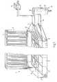
- Fig. 1shows a two-chamber photoreactor 1 from a flow reactor in the form of a trough-like vessel 2 with a lid 3 which is hinged about hinges 4 to the trough-like vessel 2 and is held in the closed position by a snap lock.
- the vessel 2is made of metal such as stainless steel, but can also be made from any other UV-resistant and other requirements, e.g. B. food regulations, sufficient material (stoneware, enamelled sheet metal, etc.).
- the lid 3carries a series of parallel paraboloid reflectors with a particularly UV-reflecting surface.
- UV emitters 6are arranged perpendicular to the flow direction so that the flow cross section of the trough-like vessel 2 is irradiated evenly, including the edge areas.
- Water-cooled, antimony-doped xenon high-pressure lampsare used for the purpose of disinfection; alternatively, low-pressure mercury quartz lamps of known design are also suitable for this.
- High-pressure mercury lamps or other emitters of suitable emission rangescan also be used for cleaning in the presence or absence of oxidizing agents.
- the snap lockis connected to a safety circuit by means of which the radiators 6 are automatically switched off when the snap lock is opened.
- the trough-like vessel 2is divided in the flow direction by quartz glass panes 7 into two radiation chambers 8 and 9; the radiation chamber 9, as the lower radiation chamber, is limited by the quartz glass panes 7 to a fixed layer thickness of 2 cm, while the layer thickness of the medium in the radiation chamber 8 can be varied with the aid of the level controller 17 described below.
- the quartz glass panes 7are mounted on a removable bracing frame 10 made of stainless steel; the quartz glass discs 7 are attached to the face frame 10 and the latter itself is fastened in a sealing manner to the inner wall of the trough-like vessel 2 by means of a cement which is resistant to UV radiation. Instead of cementing, the seal can also be made using preformed and UV-resistant seals.
- the radiation chambers 8, 9communicate with one another at their end facing away from the entrance and exit of the trough-like vessel 2.
- the upper radiation chamber 8is connected to a flow limiter 12 via a feed line 11.
- the flow limiterserves to limit the flow to the permissible maximum value even when the inlet pressure is increased; such flow restrictors are sold, for example, by Eaton Corp., Controls Division, 191 East North Ave., Carol Stream, Illinois 60 187, USA.
- the feed line 11opens into the radiation chamber 8 via a perforated plate 13, which represents a compensation element for the flow profile and extends over the entire width of the radiation chamber 8.
- the irradiation chamber 9opens out via a similar perforated plate 15, which also acts as a compensating element for the flow profile, into a discharge line 16 with a level controller 17, which has an air-permeable cover 18, for. B. made of cotton.
- the perforated plates 13, 15consist of material which is resistant to UV radiation and the medium flowing through and does not itself emit any disturbing impurities to the medium flowing through (stainless steel, coated metals, plastic, ceramic, quartz, glass).
- the width of the holesis so large that the flow is not significantly impeded, but a flow profile which is uniform over the passage area is nevertheless produced.
- the holescan also be replaced by openings of a different shape, such as slots.
- the perforated plates 13, 15are cemented in a suitable manner with the trough-like vessel 2 on the one hand and the transition piece of the supply line 11 or the discharge line 16 on the other hand.
- the level controller 17has an inner tube 19, which is guided in a sealed manner in an overflow vessel 20 and is vertically displaceable and forms the outlet of the trough-like vessel 2. By vertically displacing the inner tube 19 in the level controller 17, different layer thicknesses can be adjusted in the upper radiation chamber 8 in adaptation to the optical density of the medium entering the flow reactor through the feed line 11.
- the flow dose rate of this two-chamber photoreactor with parallel radiationis made up of the proportions of the two radiation chambers.
- the two-chamber photoreactor 1has perpendicular to the flow direction 30 low-pressure mercury quartz lamps (15 W, NN 15/44 Original Hanau Quarzlampen GmbH, Hanau), which are distributed equally over the radiation chambers 8, 9 of 80 cm in length, each radiator in an assigned reflector and the lamp-reflector combinations are each arranged at the smallest possible distance from one another.
- the tablealso shows the UV transmittances T 1 and T 2 of the medium which are important in practice in the radiation chambers 8 and 9, respectively.
- the specified flow dose rates Q-40do not make any statements about the possible flow rates unless the smallest cross-sections or highest flow velocities in the chambers are taken into account at the same time.
- the above-described two-chamber photoreactor in Table 1does not allow high flow rates in the free flow of the medium. Such photoreactors will therefore be used for lower flow rates with higher minimum doses, but one can also work with radiation sources of lower power.
- a modified embodiment of the two-chamber photoreactor 1 described above with radiation chambers arranged in parallel planesconsists of a trough-like vessel with two opposite walls made of quartz glass. Each of these UV-permeable walls is assigned a radiation source, the emitters of which are arranged opposite one another in pairs in a system of individual reflectors.
- the superimposition of the radiation fieldsresults in a substantial increase and other spatial distribution of the internal irradiance, which, with appropriate coordination of the layer thickness and transmission factor, enables an increase in the minimum dose rate of over 200%.
- double-sided irradiationachieves three times the minimum dose rate that can be achieved with the same power with one-sided irradiation.
- Multi-chamber photoreactors with an annular arrangement of radiation source and flow reactorare constructed from a plurality of tube pieces made of quartz glass, which are arranged one inside the other and whose diameters are selected such that coaxial radiation chambers of the desired layer thickness are formed.
- quartz glass tubescan be manufactured with the desired accuracy in dimensions and are commercially available with suitable diameters and wall thicknesses.
- the quartz glass tubesare centered to one another in a known manner and held between closure parts (swu), which close off the flow reactor at the end.
- the closure partshave z. B. sealed by gland packing grooves for the quartz glass tubes and are provided with internal channels and connecting pieces, through which the supply and discharge of the medium is effected when the radiation chambers are connected in parallel and when the radiation chambers are connected in series.
- Figures 2 to 4show examples of annular multi-chamber photoreactors with internal radiation.
- FIG. 2shows a two-chamber photoreactor 200.
- a flow reactor 201is formed by a radiation-impermeable outer jacket 202, by a first closure part 203 and a second closure part 204 and by a radiation-permeable inner cladding tube 205 which is held by both closure parts 203 and 204.
- the inner cladding tube 205is a quartz glass tube that is open on both sides.
- the flow reactor 201is divided into two radiation chambers 209, 211 by a quartz glass tube 207, the ends of which are held on the closure parts 203 and 204, respectively.
- the outer jacket 202is provided at both ends with ring flanges 212 which have bores 213 distributed along their circumference. On the outside of the ring flanges 212 there are recesses 214 for receiving sealing O-rings 215.
- the closure parts 203, 204carry flanges 216 with bores 217 distributed along their circumference.
- the outer jacket 202 and the closure parts 203, 204are secured by threaded bolts 218, which extend through the bores 213 and 217 and are secured by nuts 219, firmly and sealingly connected to one another.
- the outer jacket 202like the outer jacket 102 of the three-chamber photoreactor 100 according to FIG. 2, is provided with an opening 220 and a tube 221 with an annular flange 222 and cover 223 for observation or control purposes. Furthermore, the outer jacket 202 carries a lateral connection piece 224 near the end which is adjacent to the closure part 203.
- the outer jacket 202, the closure parts 203, 204 and the quartz glass tubes 205, 207are made of the same material as the corresponding parts of the three-chamber photoreactor 100.
- the closure parts 203, 204are generally ring-shaped and have an inner diameter which is closely matched to the outer diameter of the cladding tube 205.
- the closure part 203has an axial part 225, which extends from the flange 216 on its inside into the interior of the flow reactor 201 and serves to hold the cladding tube 205 or the quartz glass tube 207 at one end of the flow reactor 201.
- the closure part 203is provided with a counterbore 226, into which a stuffing box packing 127 is inserted, which is fastened with screws 133 to the outer surface of the closure part 203 and holds the cladding tube 205 firmly and sealingly at this end of the flow reactor 201.
- the axial part 225is provided with an annular recess 235 which is delimited on the outside by an annular web 237.
- the axial part 225has an outer diameter which is closely matched to the inner diameter of the quartz glass tube 207, so that one end is pushed onto the axial part 225.
- a sealing sleeve 240which is optionally secured by ligatures in the manner of hose clips, surrounds the free part of the axial part 225 and the end of the quartz glass tube 207 pushed onto the remaining part. This end of the quartz glass tube 207 is thereby held firmly and sealingly on the closure part 203.
- the closure part 203has a channel 246 opening in its outer surface, which ends in a connecting piece 247.
- the channel 246is connected at its inner end to an axial channel 248 which extends through the axial part 225 and opens into the bottom of the annular recess 235. This creates a connection between the connection piece 247 and the inner radiation chamber 209.
- the closure part 204has an axial part 265 which extends away from the flange 216 on the inside of the flow reactor 201 and serves to hold the cladding tube 205 at the other end of the flow reactor 201.
- the closure part 204is provided with a counterbore 266 into which a stuffing box packing 127 is inserted, which is fastened with screws 133 to the outer surface of the closure part 204 and holds the cladding tube 205 firmly and sealingly at this end of the flow reactor 201.
- a ring 268is fastened to the closure part 204 with screws 267, from which protruding leaf springs 269 protrude like a crown, between which a protective sleeve 270 surrounding the other end of the quartz glass tube 207 is guided.
- the closure part 204has an axially extending drain channel 249, which connects the outer radiation chamber 211 to a drain valve 250 on the outside of the flange 216.
- the flow through the two-chamber photoreactor 200takes place between the connecting pieces 224 and 247 through the radiation chambers 209 and 211, which communicate with one another through the spaces (not shown) between the leaf springs 269 projecting into the flow reactor 201 from the inner surface of the closure part 204.
- perforated plates 254, 255are provided, which are designed as in the three-chamber photoreactor 100.
- the perforated plate 254is fastened to the web 237 of the axial part 225 projecting from the annular recess 235 of the closure part 203 and acts on the flow passing through the inner radiation chamber 209.
- the perforated plate 255bears against a ring 251 fastened to the inner surface of the outer casing 202 near the connecting piece 224, which ring can thus also be formed in one piece; on the inside it lies against the end of the sealing sleeve 240.
- the perforated plate 255is by locking ring secured against displacement 256; it acts on the flow passing through the outer radiation chamber 211.
- the flow dose rate of the two-chamber photoreactor 200 with radially outward radiationis correspondingly composed of the flow dose rate components of the two irradiation chambers 209 and 211.
- the exact derivation for the maximum of the flow dose rateis complicated, as already explained at the beginning. Therefore, the approximation described at the beginning was assumed for the following presentation.
- the maximum of the flow dose rate within limited rangesdepends only little on the layer thickness d i or is only slightly influenced by changes in the UV permeability of the medium.
- Embodiment a)relates to a two-chamber photoreactor 200 which is adapted to media whose UV transmittance is variable according to lower values, while embodiment b) is adapted to media whose UV transmittance is variable to higher values.
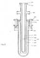
- FIG. 3A further embodiment of an annular two-chamber photoreactor is shown in FIG. 3.
- the two-chamber photoreactor 600 shown thereinis also constructed coaxially according to the diving lamp principle.
- the cladding tube 605is surrounded by a separating tube 606 made of quartz glass or another UV-transparent material, so that in the vessel 602 an irradiation chamber 609 immediately adjacent to the radiation source and a further irradiation chamber 611 are formed.
- the vessel 602is provided with an observation device 620, which is made of UV-permeable material and can be a quartz glass pane melted into the quartz material vessel 602.
- the separating tube 606is provided with a welded-on ring flange 616 made of quartz material.
- the contact surface of the ring flange facing the end face 612 of the vessel 602is ground flat and lies on the end face 612 via a seal 617 made of polytetrafluoroethylene.
- the vessel 602is sealed with a clamp ring 618 (Schott & Gen., Mainz), which engages the ring flange 616 and the reinforced end of the vessel 602.
- the separating tube 606Above the ring flange 616, the separating tube 606 carries two diametrically opposed lateral connections 647.
- the separating tube 606is provided with a flange ring 619 made of quartz material, which is fused to a corresponding flange ring 615 at the outer end of the cladding tube 605, as a result of which the radiation chamber 609 is sealed is.
- a wide maximum of 12.3 m 3 / hcan be seen with the selected layer thicknesses.
- the linear flow rate in the radiation chamber 609is included in the entire range favorable values above 0.1 to 0.3 m / s.
- UV lamps with radiation powers of 21 W per cm of arc length (mercury medium pressure lamps with arc lengths of 20 or 30 cm, antimony-doped high-pressure xenon lamps, Original Hanau Quarzlampen GmbH; mercury low-pressure special lamps, from Gräntzel), compact photoreactors of high power can be obtained at reasonable prices Costs that can be used for media with highly variable UV permeability.
- the high flow velocities in the irradiation chamber 609 immediately adjacent to the radiation sourceoffer great security against malfunctions even when the composition of the medium to be irradiated is relatively variable.
- Corresponding applicationsare emergency water supply systems that can be operated with emergency power generators.
- Flow dose rates Q-40 in the range from 15 to 20 m 3 / h, which are sufficient for the emergency water supply of 1500 people,are obtained with the aforementioned high-performance radiators.
- the two-chamber photoreactors 600are suitable for the independent disinfection of well water or spring water.
- the maximum flow of multi-chamber photoreactorsis limited by the smallest chamber cross-section or, if the lengths are the same, by the smallest chamber volume.
- the dimensions of the innermost chambershould have this limiting function, since the chamber cross-sections increase rapidly with the same thickness as the distance from the center or from the axis increases.
- the radiation doses effective in the two radiation chambersbehave like the volumes or passage cross sections of the radiation chambers.
- the relatively small change in the flow dose rate with the layer thickness d i with a constant total layer thickness in the region of the maximumenables the volumes of the two radiation chambers to be made the same size without significant deterioration in the flow dose rate.
- the layer ratioscan thus be largely adapted to the respective requirements of the flow velocities at high or low flow rates, the flow dose rate always being substantially above that achievable with single-chamber photoreactors.
- a three-chamber photoreactor 100 set up for internal radiationis shown half in longitudinal section in FIG. It contains a radiator 24 of the aforementioned type, which can be single or multiple turns to increase the irradiance in the photoreactor 100.
- the radiator 24is arranged near the axis in the interior of a flow reactor 101, which is formed by a radiation-impermeable outer jacket 102, by a first closure part 103 and a second closure part 104 and by a radiation-impermeable inner cladding tube 105 which is held in the first closure part 103.
- the inner cladding tube 105is a quartz glass tube which is closed on one side and at the closed end of which the radiator 24 rests on a glass wool packing 27.
- the flow reactor 101is divided into three radiation chambers 109, 110, 111 by a quartz glass tube 106 and a quartz glass tube 107 which is closed on one side and has through openings 108 in the wall at its open end, both of which are likewise held in the first closure part 103.
- the outer jacket 102is provided at both ends with ring flanges 112 which have bores 113 distributed along their circumference. On the outside of the ring flanges 112 there are recesses 114 for receiving sealing O-rings 115.
- the closure parts 103 and 104carry flanges 116 with holes 117 distributed along their circumference, the number and diameter of which correspond to the holes 113 in the ring flanges 112 of the outer casing 102 .
- the outer casing 102 and the closure parts 103, 104are arranged with the ring flanges 112 and the flanges 116 such that the bores 113 and 117 are aligned so that these parts are firmly connected to one another by threaded bolts 118 which extend through the bores 113 and 117 and nuts 119 can be connected.
- the outer jacket 102is provided with an opening 120 in the region of the radiation field of the radiator 24, into which an opening 121 has an outer ring flange 122 is fitted.
- the tube 121is sealed by a tight and tight, e.g. B. by screwing, connected to the ring flange 122 connected cover 123.
- the tube 121is connected via a quartz window to the photoreactor of a monitoring device for the radiation passing through the flow reactor 101.
- the outer jacket 102can be provided with a material reflecting the UV rays into the medium in order to utilize the UV power radiated onto the outer jacket 102 when the medium has a high transmission factor.
- the reflective surfacecan also be arranged on the outside, thereby avoiding influences on the reflectivity by the medium.
- the outer casing 102 and the closure parts 103, 104consist of metal such as stainless steel, of metals with a protective coating of glass, enamel or plastic, of galvanized iron sheet, of ceramic; Any material of suitable mechanical strength can be used for this, which is resistant to UV radiation and does not release any foreign substances or pollutants into the medium flowing through.
- the cladding tube 105 and the quartz glass tubes 106, 107can in the areas that lie outside the radiation field of the radiator 24 with extension pieces, for. B. made of sintered quartz.
- the closure part 103is generally ring-shaped and has an inner diameter which is closely matched to the outer diameter of the cladding tube 105.
- the annular closure part 103carries two axial parts 124, 125, which extend on both sides of the flange 116 on its inner edge and serve to hold the cladding tube 105 or the quartz glass tubes 106 and 107.
- the first axial part 124is provided on its outer end with a counterbore 126 into which a stuffing box packing 127 is inserted.
- the stuffing box packing 127consists of two O-rings 128, 130 separated by a guide ring 129, which are formed by a pressure ring 131 with an annular flange 132, which is fastened by screws 133 to the outer surface of the first axial part 124, against the one formed at the end of the counterbore 126 Shoulder 134 are pressed. As a result, the cladding tube 105 is held firmly and sealed on the first axial part 124.
- the second axial part 125is provided from the inside with three concentric annular grooves 135, 136 and 137, the depth of which decreases from the inside to the outside and form the annular webs 138, 139, 140 and 141.
- the webs 138 and 139have small and different axial depths and delimit the innermost, deepest ring groove 135.
- the middle ring groove 136is delimited by the web 139 and the longer web 140, while the outermost, shallowest ring groove 137 by two webs 140 of the same depth. 141 is included.
- the central annular groove 136serves to receive the quartz glass tube 106, the end of which lies against the bottom of the annular groove 136 via an O-ring 142; a bushing 143 surrounds the O-ring 142 and the upper end of the quartz glass tube 106.
- the quartz glass tube 106is held firmly and sealed in the central ring groove 136 by a stuffing box packing 127, which is fastened to the outer surface of the web 140 with screws 133.
- the outer annular groove 137serves to receive the quartz glass tube 107, which is closed on one side, the open end of which lies against the bottom of the annular groove 137 via an O-ring 144; a bushing 145 surrounds the O-ring 144 and the open end of the quartz glass tube 107, which is closed on one side.
- the quartz glass tube 107is tightly and sealed above the passage openings 108 in the through a gland packing 127, which is fastened to the outer surface of the web 141 with screws 133 outer annular groove 137 held.
- the closure part 103has two radial channels 146 which open diametrically opposite in the peripheral surface of the flange 116 and which end in connecting pieces 147. At its inner end, the radial channels 146 are connected to an axial channel 148 which branches off at a right angle and opens into the bottom of the annular groove 135. This creates a connection between the connecting piece 147 and the inner radiation chamber 109.
- the flange 116additionally has an axially extending ventilation channel 149, which connects the outer radiation chamber 111 to a ventilation valve 150 on the outside of the flange 116.
- the closure part 104consists of a plate 151 with a central connecting piece 152.
- the inner surface of the plate 151lies on a ring 153 which lies circumferentially against the inner wall of the outer casing 102.
- the flow through the three-chamber photoreactor 100takes place between the connecting pieces 147 and 152 through the radiation chambers 109, 110 and 111, the radiation chambers 110 and 111 communicating with one another through the through openings 108 in the wall of the quartz glass tube 107 closed on one side.
- annular perforated plates 154, 155are provided. The perforated plate 154 is fastened to the web 139 of the second axial part 125 of the first closure part 103 and acts on the flow passing through the inner radiation chamber 109.
- the perforated plate 155lies against the ring 153 lying on the inner surface of the plate 151 of the second closure part 104 and acts the flow passing through the outer irradiation chamber 111; the quartz glass tube 107 bears on its inner edge, which is additionally guided at its closed end.
- the perforated plates 154, 155consist of material which is resistant to UV radiation and the medium flowing through and does not itself emit any foreign or harmful substances to the medium (stainless steel, coated metals, plastic, ceramic, quartz, glass).
- the width of the holesis so large that the flow is not significantly impeded, but one over the Passage area is generated uniform flow profile.
- the holescan also be replaced by openings of another suitable shape, such as slots.
- the direction of flowdoes not play a role for the continuous operation of the three-chamber photoreactor 100. However, there may be significant differences when starting up the business. In the event of repeated interruptions in operation, it may be desirable to obtain medium of the required degree of purity or sterilization after a very short start-up time. It is then expedient to let the medium flow via the connection piece 152 from the outer radiation chamber 111 through the inner radiation chamber 109 to the connection piece 147. With the same direction of flow, in cases of precipitation formation, it can be achieved that the disruptive effect initially remains limited to the outer radiation chambers and does not question the overall result too quickly. For reasons of lamp cooling, however, the flow direction from the inside to the outside will generally be preferred, likewise in the case of fumigation.
- the three-chamber photoreactor 100 shown in FIG. 4represents a combination of a two-chamber photoreactor which is optimized with regard to the flow dose rate and which is combined with an additional radiation chamber 109 which is directly adjacent to the radiation source in such a way that an optimal flow rate dose rate is achieved.
- Table 6shows the data for such combinations, which are adapted in Table 6a) and 6b) according to Table 3a) and 3b) to media with UV transmittances which vary according to lower or higher values.
- Table 7shows the UV radiation doses effective in the radiation chambers 109, 110 and 111, as well as the UV permeability or the flow dose rate Q-40 overall and the of the inner radiation chambers 109 and 110 which form the two-chamber photoreactor.
- this three-chamber photoreactorcan be used almost universally in the range of the UV permeability occurring for water.
- Such extensive adaptation of a photoreactor to such different UV permeabilitiescannot be achieved in two-chamber photoreactors.
- the three-chamber photoreactor described above in connection with FIG. 4 and Table 7shows one of the advantages of the multi-chamber principle, namely the optimal adaptation of a photoreactor to a very wide range of different water qualities.
- the multi-chamber principlealso offers special advantages in a range of water qualities for the highest demands, such as those found in B. in the electronics industry, in the pharmaceutical industry or medicine for. B. for Aqua ad injectabilia.
- An adaptation of the photoreactor to an increasing UV permeability of the water during the irradiationis particularly desirable if, in addition to the bactericidal effect, an oxidative removal of organic traces of contamination is also sought.
- the layer thickness of the irradiation chambers surrounding the respective cladding tubes and the distance between the individual irradiation units in the tank reactor according to FIGS. 2 to 8 of the earlier applicationcan also be selected such that the optimum conditions for annular two- or three-chamber photoreactors given above are at least approximately achieved will.
Landscapes
- Life Sciences & Earth Sciences (AREA)
- Engineering & Computer Science (AREA)
- Health & Medical Sciences (AREA)
- Chemical & Material Sciences (AREA)
- Public Health (AREA)
- Zoology (AREA)
- Water Supply & Treatment (AREA)
- Hydrology & Water Resources (AREA)
- Organic Chemistry (AREA)
- Epidemiology (AREA)
- Animal Behavior & Ethology (AREA)
- General Health & Medical Sciences (AREA)
- Toxicology (AREA)
- Veterinary Medicine (AREA)
- Wood Science & Technology (AREA)
- Environmental & Geological Engineering (AREA)
- Food Science & Technology (AREA)
- Polymers & Plastics (AREA)
- Physical Or Chemical Processes And Apparatus (AREA)
- Physical Water Treatments (AREA)
- Apparatus For Disinfection Or Sterilisation (AREA)
- Heating, Cooling, Or Curing Plastics Or The Like In General (AREA)
- External Artificial Organs (AREA)
- Photoreceptors In Electrophotography (AREA)
- Water Treatment By Sorption (AREA)
Abstract
Description
Translated fromGermanDie Erfindung betrifft ein Verfahren zur Reinigung, bei dem ein fließfähiges Medium zur Einhaltung einer vorbestimmten Mindestdosis ultravioletter Strahlung im Wellenlängenbereich von 240 bis 320 nm, vorzugsweise 260 bis 280 nm, mit einem bestimmten Durchfluß durch einen Durchflußreaktor gefördert wird, der durch nicht mehr als zwei für die ultraviolette Strahlung durchlässige Trennwände senkrecht zur Durchstrahlungsrichtung in nicht mehr als drei in Durchströmungsrichtung hintereinandergeschaltete Bestrahlungskammern jeweils gleichbleibender Schichtdicke unterteilt ist, wobei ein Bruchteil von mindestens 50% der Strahlung, die in die der Strahlungsquelle unmittelbar benachbarte Bestrahlungskammer eindringt, mindestens in die direkt folgende Bestrahlungskammer fällt, und die in den Durchflußreaktor eindringende Strahlung in allen Bestrahlungskammern zusammen höchstens zu 87,5% absorbiert wird. Sie betrifft auch einen Mehrkammer-Photoreaktor zur Ausübung des Verfahrens bestehend aus einer Strahlungsquelle mit mindestens einem Strahler, aus einem durch nicht mehr als zwei für die ultraviolette Strahlung durchlässige Trennwände in nicht mehr als drei in Durchströmungsrichtung hintereinandergeschaltete Bestrahlungskammern gleichbleibender Schichtdicke unterteilten Durchflußreaktor mit einer Zuleitung und einer Ableitung für das zu bestrahlende Medium, dessen Bestrahlungskammern in bezug auf die durch die Strahlungsquelle bestimmte Durchstrahlungsrichtung hintereinander angeordnet sind, wobei die in das Medium mindestens in der Bestrahlungskammer, die der der Strahlungsquelle unmittelbar benachbarten Bestrahlungskammer direkt folgt, einfallende Strahlung einen Bruchteil von mindestens 50% der Strahlung beträgt, die in die der Strahlungsquelle unmittelbar benachbarte Bestrahlungskammer eindringt, und die Gesamtschichtdicke aller Bestrahlungskammern nach einer Absorption von nicht mehr als 87.5% der in den Durchflußreaktoreindringenden Strahlung bemessen ist.The invention relates to a method for cleaning, in which a flowable medium for maintaining a predetermined minimum dose of ultraviolet radiation in the wavelength range from 240 to 320 nm, preferably 260 to 280 nm, is conveyed with a certain flow through a flow reactor, which by no more than two Partitions permeable to ultraviolet radiation are divided perpendicularly to the direction of radiation into no more than three radiation chambers connected in series in the direction of flow, each with a constant layer thickness, a fraction of at least 50% of the radiation penetrating into the radiation chamber immediately adjacent to the radiation source, at least into the radiation chamber immediately following falls, and the radiation penetrating into the flow-through reactor is absorbed in all radiation chambers together at most to 87.5%. It also relates to a multi-chamber photoreactor for carrying out the process consisting of a radiation source with at least one radiator, a flow reactor with a feed line and no more than two partition walls which are permeable to the ultraviolet radiation in no more than three radiation chambers connected in series in the flow direction and having a constant layer thickness a discharge line for the medium to be irradiated, the radiation chambers of which are arranged one behind the other in relation to the radiation direction determined by the radiation source, the radiation incident in the medium at least in the radiation chamber, which directly follows the radiation chamber immediately adjacent to the radiation source, a fraction of at least 50 % of the radiation that penetrates into the radiation chamber immediately adjacent to the radiation source, and the total layer thickness of all radiation chambers after an absorption of not more than 87.5% of the radiation entering the flow reactor is measured.
Sowohl das erfindungsgemäße Verfahren als auch die Vorrichtung zu seiner Durchführung sind dadurch gekennzeichnet, daß das Medium durch zwei in Durchstrahlungsrichtung und in Durchströmungsrichtung unmittelbar hintereinander angeordnete Bestrahlungskammern gefördert wird, in deren engerer im Bereich von 30,8 bis 47,4% und in denen zusammen im Bereich von 64,5 bis 83,2% der eindringenden Strahlung absorbiert wird.Both the method according to the invention and the device for its implementation are characterized in that the medium is conveyed through two radiation chambers arranged one behind the other in the direction of radiation and in the direction of flow, in their narrower in the range from 30.8 to 47.4% and in those together is absorbed in the range of 64.5 to 83.2% of the penetrating radiation.
Besondere Ausführungsformen dieser Gegenstände sind untenstehend erläutert und in den Unteransprüchen noch im einzelnen definiert.Particular embodiments of these subjects are explained below and are still defined in detail in the subclaims.
Bekannte Verfahren und Vorrichtungen dieser Art (EP-A-0 000 773; Nachpubl.) haben besondere Vorteile, die durch die Kombination der Wirkungen der UV-Strahlung in den verschiedenen Bestrah-Iungskanmmern gegenüber den derzeit benutzten bekannten Einkammer-Photoreaktoren, aber auch gegenüber bekannten Mehrkammer-Photoreaktoren anderer Konstruktion erzielt werden. Darin ist auch angegeben, daß eine bedeutende Zunahme in der Effizienz dadurch erreicht wird, daß die Absorption durch das Medium in der der Strahlungsquelle unmittelbar benachbarten Bestrahlungskammer auf nicht mehr als 50% und die Gesamtabsorption auf mit der Anzahl der Bestrahlungskammern zunehmende Werte, z. B. 75% bei zwei Bestrahlungskammern und 87.5% bei drei Bestrahlungskammern, begrenzt wird.Known methods and devices of this type (EP-
Bei einem bekannten annularen Zweikammer-Photoreaktor mit radialer Durchstrahlung (US-A-2 669 661) ist die Gesamtschichtdicke so bemessen, daß die Gesamtabsorption durch beide Bestrahlungskammern mindestens 90% beträgt, und die Trennwand zwischen den beiden Bestrahlungskammern so angeordnet, daß die auf die Trennwand fallende Strahlungsintensität der über die Apparatur gemittelten Intensität mindestens gleich ist. Das entspricht einer Absorption von nicht mehr als 53.5% in der engeren Bestrahlungskammer. Mit einer solchen Apparatur soll ein Maximum an Wirkung und Wirksamkeit erzielt werden.In a known annular two-chamber photoreactor with radial transmission (US-A-2 669 661), the total layer thickness is dimensioned such that the total absorption through both radiation chambers is at least 90%, and the partition between the two radiation chambers is arranged so that the on Partition wall falling radiation intensity is at least equal to the intensity averaged over the apparatus. This corresponds to an absorption of no more than 53.5% in the narrower radiation chamber. Such an apparatus is intended to achieve maximum effectiveness and effectiveness.
Durch die FR-A-2308409 ist ein Photoreaktor zur Bestrahlung von Flüssigkeiten oder Gasen durch UV-Strahlung bekannt, bei dem das zu bestrahlende Medium parallel durch mehrere Bestrahlungskammern gefördert wird, von denen wenigstens zwei gleichzeitig der Strahlung von mehreren Strahlungsquellen ausgesetzt werden.FR-A-2308409 discloses a photoreactor for the irradiation of liquids or gases by UV radiation, in which the medium to be irradiated is conveyed in parallel through a plurality of radiation chambers, at least two of which are simultaneously exposed to the radiation from a plurality of radiation sources.
Ein weiterer bekannter Photoreaktor (US-A-3 637 342) besteht aus einem im wesentlichen zylinderförmigen Gefäß, das durch zwei UV-durchlässige Trennwände in eine mittlere Bestrahlungskammer, die von mehreren Strahlern durchsetzt ist, und zwei seitliche Bestrahlungskammern von segmentförmigem Querschnitt unterteilt ist. Die drei Bestrahlungskammern werden nacheinander von dem zu bestrahlenden Medium durchströmt.Another known photoreactor (US-A-3 637 342) consists of a substantially cylindrical vessel which is divided by two UV-transparent partition walls into a central radiation chamber, through which several emitters are penetrated, and two lateral radiation chambers of segment-shaped cross-section. The three radiation chambers are successively flowed through by the medium to be irradiated.
Die vorliegende Erfindung geht von der Erkenntnis aus, daß die erzielbare Durchflußdosisleistung eines Einkammer-Photoreaktors bei einer vorgegebenen Mindestdosis durch die Schichtdicke bestimmt ist, wobei die Durchflußdosisleistung von dem Kammervolumen und von der wirksamen Strahlungsintensität abhängig ist. Die Durchflußdosisleistung Q-M bei der vorbestimmten Mindestdosis M (in Milliwattsekunden pro cm2) ergibt sich aus dem Durchfluß Q (in m3/h) und der Strahlungsstärke (in Milliwatt pro cm2) und ist eine Funktion des Volumens V des Mediums und der Strahlungsdosis E
Darin ist Q-M die Durchflußdosisleistung bei der verlangten Mindestdosis M, V das Kammervolumen und E die Strahlungsintensität. Der Berechnung ist dabei die minimale in dem Kammervolumen V wirksame Strahlungsintensität und nicht die in den Photoreaktor eindringende Strahlungsintensität zugrunde zu legen. Das Kammervolumen nimmt mit zunehmender Schichtdicke d zu, während die wirksame Strahlungsintensität mit zunehmender Schichtdicke d abnimmt.
Es ergibt sich daraus nach den Regeln der Differentialrechnung ein Maximum der Durchflußdosisleistung


Das Kammervolumen ist

Für einen Einkammer-Photoreaktor mit paralleler Durchstrahlung ergibt sich daraus ein Maximum der Durchflußdosisleistung bei
- d. h. dk = 1 bzw. d · In T = 1
- bzw. ε · d = log e bzw. d · log T = log e
- ie dk = 1 or d · In T = 1
- or εd = log e or dlog T = log e
Darin ist k der auf die Basis e bezogene Extinktionskoeffizient des zu bestrahlenden Mediums bei einer Wellenlänge von 254 nm, der im gesamten Wellenlängenbereich der wirksamen UV-Strahlung zugrunde gelegt wird; T ist die in einer 1-cm-Küvette, ebenfalls bei der Wellenlänge von 254 nm gemessene UV-Durchlässigkeit des zu bestrahlenden Mediums; ist der spezifische dekadische Extinktionskoeffizient. Das Produkt ε · d wird üblicherweise als Extinktion bezeichnet. Unter »Absorption« wird in diesem Zusammenhang der in der Schichtdicke d absorbierte Anteil A der eindringenden Strahlungsintensität Eo verstanden, der sich aus dem Lambert-Beerschen Absorptionsgesetz nach A = Eo-Ed ergibt und auch in % der eindringenden Strahlungsintensität Eo ausgedrückt werden kann.K is the extinction coefficient of the medium to be irradiated at a wavelength of 254 nm, which is based on the basis of the effective UV radiation in the entire wavelength range; T is the UV permeability of the medium to be irradiated, measured in a 1 cm cuvette, likewise at the wavelength of 254 nm; is the specific decadic extinction coefficient. The product ε · d is usually referred to as extinction. In this context, “absorption” means the portion A of the penetrating radiation intensity Eo absorbed in the layer thickness d, which is derived from the Lambert-Beer absorption law according to A = Eo -Ed and is also expressed in% of the penetrating radiation intensity Eo can be.
Für einen Einkammer-Photoreaktor mit radial von innen nach außen gerichteter Durchstrahlung, bei dem die Bestrahlungskammer koaxial zu einem die Strahlungsquelle umgebenden Hüllrohr mit dem Radius r, angeordnet ist, sind

Daraus erhält man
Während die vollständige Differentiation der vorstehenden Gleichung zu einem komplizierten Ausdruck führt, ergibt eine näherungsweise Betrachtung, daß der Quotient


Die vorgenannten Einkammer-Photoreaktoren besitzen somit ein Maximum der Durchflußdosisleistung bei einer Schichtdicke d, bei der die Intensität der durch die Einstrahlungsfläche eintretenden wirksamen Strahlung Eo auf e-1, d. h. 36.8%, im Falle paralleler Durchstrahlung und auf e0826, d. h. 43.7%, im Falle radialer Durchstrahlung abgefallen ist. Bei kleineren Schichtdicken verschlechtert sich die Durchflußdosisleistung wegen mangelnder Ausnutzung der zur Verfügung stehenden Strahlungsintensität. Bei höheren Schichtdicken verschlechtert sich die Durchflußdosisleistung wegen des zunehmenden Beitrags von Teilvolumina, die nur einer geringen wirksamen Strahlungsintensität ausgesetzt sind. Anders ausgedrückt ergibt sich, daß ein in seiner Schichtdicke d vorgegebener Einkammer-Photoreaktor die von der Strahlungsquelle eingestrahlte UV-Strahlung nur für Medien eines relativ eng begrenzten Bereichs von UV-Dürchlässigkeiten optimal nutzt.The aforementioned single-chamber photoreactors thus have a maximum of the flow dose rate at a layer thickness d at which the intensity of the effective radiation Eo entering through the irradiation surface is set to e-1 , ie 36.8%, in the case of parallel radiation and e0826, ie 43.7% has dropped in the case of radial radiation. With smaller layer thicknesses, the flow dose rate deteriorates due to a lack of utilization of the available radiation intensity. With higher layer thicknesses, the flow dose rate deteriorates because of the increasing contribution of partial volumes that are only exposed to a low effective radiation intensity. In other words, a single-chamber photoreactor with a predetermined layer thickness d uses the UV radiation radiated by the radiation source optimally only for media of a relatively narrow range of UV permeability.
Die Aufgabe der vorliegenden Erfindung besteht darin, einen Mehrkammer-Photoreaktor der eingangs genannten Art zu schaffen, der eine optimale Ausnutzung der in den Reaktor eintretenden UV-Strahlung gestattet. Ein solcher Reaktor soll möglichst so beschaffen sein, daß die UV-Strahlung über weite UV-Durchlässigkeitsbereiche der zu bestrahlenden Medien, zumindest aber innerhalb der vorkommenden Variationen in der UV-Durchlässigkeit des Mediums optimal genutzt wird. Dabei soll insbesondere im Zusammenhang mit der Wasserentkeimung sichergestellt sein, daß die Strömungsgeschwindigkeit in der Strahlungsquelle unmittelbar benachbarten Bestrahlungskammer ausreicht, Abscheidungen unter der Einwirkung auch hoher Strahlungsintensitäten zu verhindern.The object of the present invention is to provide a multi-chamber photoreactor of the type mentioned at the outset, which allows optimal use of the UV radiation entering the reactor. Such a reactor should, if possible, be such that the UV radiation is used optimally over wide UV permeability ranges of the media to be irradiated, or at least within the occurring variations in the UV permeability of the medium. In connection with water disinfection in particular, it should be ensured that the flow velocity in the radiation source immediately adjacent to the radiation chamber is sufficient to prevent deposits under the influence of even high radiation intensities.
Diese Aufgabe wird durch die in den Patentansprüchen angegebenen kennzeichnenden Merkmale gelöst. Vorteilhafte Ausbildungen und Weiterentwicklungen der Erfindung sind durch die in den Unteransprüchen angegebenen Merkmale gekennzeichnet. Deren Besonderheiten werden im Zusammenhang mit den Ausführungsbeispielen erörtert.This object is achieved by the characterizing features specified in the patent claims. Advantageous developments and further developments of the invention are characterized by the features specified in the subclaims. Their peculiarities are discussed in connection with the exemplary embodiments.
Ausführungsbeispiele der erfindungsgemäßen Vorrichtung sind in den Abbildungen dargestellt und werden nachfolgend im einzelnen erläutert und beschrieben. Es zeigt
- Fig. 1 eine perspektivische Ansicht eines ersten Ausführungsbeispiels des erfindungsgemäßen Mehrkammer-Photoreaktors;
- Fig. 2 einen Längsschnitt durch ein zweites Ausführungsbeispiel des erfindungsgemäßen Mehrkammer-Photoreaktors;
- Fig. 3 einen Längsschnitt durch ein drittes Ausführungsbeispiel des erfindungsgemäßen Mehrkammer-Photoreaktors;
- Fig. 4 einen Längsschnitt durch einen Teil eines vierten Ausführungsbeispiels des erfindungsgemäßen Mehrkammer-Photoreaktors.
- Figure 1 is a perspective view of a first embodiment of the multi-chamber photoreactor according to the invention.
- 2 shows a longitudinal section through a second exemplary embodiment of the multi-chamber photoreactor according to the invention;
- 3 shows a longitudinal section through a third exemplary embodiment of the multi-chamber photoreactor according to the invention;
- Fig. 4 shows a longitudinal section through part of a fourth embodiment of the multi-chamber photoreactor according to the invention.
Fig. 1 zeigt einen Zweikammer-Photoreaktor 1 aus einem Durchflußreaktor in Gestalt eines trogartigen Gefäßes 2 mit einem Deckel 3, der um Scharniere 4 schwenkbar an das trogartige Gefäß 2 angelenkt ist und durch einen Schnappverschluß in geschlossener Stellung gehalten wird. Das Gefäß 2 besteht aus Metall wie rostfreiem Stahl, kann aber auch aus jedem anderen UV-beständigen und sonstigen Anforderungen, z. B. lebensmittelrechtlichen Bestimmungen, genügendem Material (Steinzeug, emailliertes Blech etc.) gefertigt sein. Der Deckel 3 trägt innen eine Serie von zueinander parallelen paraboloiden Reflektoren mit einer besonders gut UV-reflektierenden Oberfläche. Innerhalb der Reflektoren sind UV-Strahler 6 senkrecht zur Durchströmungsrichtung so angeordnet, daß der Strömungsquerschnitt des trogartigen Gefäßes 2 unter Einschluß der Randbereiche gleichmäßig bestrahlt wird. Für Zwecke der Entkeimung werden wassergekühlte, antimondotierte Xenon-Hochdrucklampen eingesetzt; alternativ eignen sich dafür auch Quecksilberniederdruck-Quarzlampen bekannter Bauart. Für die Reinigung in Anwesenheit oder Abwesenheit von Oxidationsmitteln kann man auch Quecksilberhochdrucklampen oder andere Strahler geeigneter Emissionsbereiche verwenden. Der Schnappverschluß ist mit einer Sicherheitsschaltung verbunden, durch die die Strahler 6 bei Öffnung des Schnappverschlusses automatisch abgeschaltet werden. Das trogartige Gefäß 2 ist in Strömungsrichtung durch Quarzglasscheiben 7 in zwei Bestrahlungskammern 8 und 9 unterteilt; die Bestrahlungskammer 9 ist als untere Bestrahlungskammer durch die Quarzglasscheiben 7 auf eine fixe Schichtdicke von 2 cm begrenzt, während die Schichtdicke des Mediums in der Bestrahlungskammer 8 mit Hilfe des weiter unten beschriebenen Niveaureglers 17 variiert werden kann. Die Quarglasscheiben 7 sind auf einem herausnehmbaren Strebrahmen 10 aus rostfreiem Stahl gelagert; die Quarzglasscheiben 7 sind an dem Strebrahmen 10 und dieser selbst ist an der Innenwandung des trogartigen Gefäßes 2 mittels eines gegen UV-Strahlung beständigen Kitts abdichtend befestigt. Anstelle der Verkittung kann die Abdichtung auch durch vorgeformte und UV-beständige Dichtungen erfolgen. Die Bestrahlungskammern 8, 9 kommunizieren an ihrem dem Ein- und Ausgang des trogartigen Gefäßes 2 abgewandten Ende miteinander. Die obere Bestrahlungskammer 8 ist über eine Zuleitung 11 an einen Durchflußbegrenzer 12 angeschlossen. Der Durchflußbegrenzer dient dazu, den Durchfluß auch bei Erhöhung des Eingangsdrucks auf den zulässigen Maximalwert zu begrenzen; solche Durchflußbegrenzer werden beispielsweise von der Firma Eaton Corp., Controls Division, 191 East North Ave., Carol Stream, Illinois 60 187, USA, vertrieben. Die Zuleitung 11 mündet in die Bestrahlungskammer 8 über eine Lochplatte 13, die ein Ausgleichselement für das Strömungsprofil darstellt und sich über die gesamte Breite der Bestrahlungskammer 8 erstreckt. Die Bestrahlungskammer 9 mündet über eine gleichartige Lochplatte 15, die ebenfalls als Ausgleichselement für das Strömungsprofil wirkt, in eine Ableitung 16 mit einem Niveauregler 17, der zum Schutz gegen Verunreinigungen eine luftdurchlässige Abdeckung 18, z. B. aus Watte, trägt.Fig. 1 shows a two-chamber photoreactor 1 from a flow reactor in the form of a trough-
Die Lochplatten 13, 15 bestehen aus Material, das gegen UV-Strahlung und gegen das durchströmende Medium beständig ist und selbst keine störenden Verunreinigungen an das durchströmende Medium abgibt (rostfreier Stahl, beschichtete Metalle, Kunststoff, Keramik, Quarz, Glas). Die Weite der Löcher ist so groß, daß die Strömung nicht wesentlich behindert ist, aber doch ein über die Durchtrittsfläche gleichmäßiges Strömungsprofil erzeugt wird. Zu dem gleichen Zwecke können die Löcher auch durch Öffnungen anderer Gestalt wie Schlitze ersetzt werden. Die Lochplatten 13, 15 sind mit dem trogartigen Gefäß 2 einerseits und dem Übergangsstück der Zuleitung 11 bzw. der Ableitung 16 andererseits in geeigneter Weise abdichtend verkittet.The
Der Niveauregler 17 besitzt ein Innenrohr 19, das abgedichtet in einem Überlaufgefäß 20 vertikal verschiebbar geführt ist und den Auslauf des trogartigen Gefäßes 2 bildet. Durch Vertikalverschiebung des Innenrohres 19 in dem Niveauregler 17 können in Anpassung an die optische Dichte des durch die Zuleitung 11 in den Durchflußreaktor eintretenden Mediums verschiedene Schichtdicken in der oberen Bestrahlungskammer 8 eingestellt werden.The
Die Durchflußdosisleistung dieses Zweikammer-Photoreaktors mit paralleler Durchstrahlung setzt sich aus den Anteilen der beiden Bestrahlungskammern zusammen. Dafür gilt
Setzt man für Zwecke der Rechnung die Gesamtschichtdicke d1+d2=D, so ergibt sich
Partielle Differentiation dieser Gleichung nach d1 und D ergibt für die maximale Durchflußdosisleistung

Daraus erhält man das Maximum der Durchflußdosisleistung bei einer Gesamtextinktion von

Der Zweikammer-Photoreaktor 1 weist senkrecht zur Durchströmungsrichtung 30 Quecksilberniederdruck-Quarzlampen (15 W, NN 15/44 Original Hanau Quarzlampen GmbH, Hanau) auf, die über die Bestrahlungskammern 8, 9 von 80 cm Länge in gleichen Abständen verteilt sind, wobei jeder Strahler in einem zugeordneten Reflektor und die Lampen-Reflektorkombinationen jeweils in geringstmöglichem Abstand voneinander angeordnet sind. Der gesamte auf die Oberfläche des Mediums gelangende UV-Strahlungsfluß beträgt (unter Berücksichtigung der Reflektionsverluste von höchstens 45% sowie der Randverluste) ca. 60 W mit einer mittleren Bestrahlungsstärke E = 25 mW/cm2. Die nachfolgende Tabelle 1 zeigt die Durchflußdosisleistung Q-M (m3/h) eines Zweikammer-Photoreaktors 1 mit der Gesamtschichtdicke D = di + d2 = 4.6 cm, wie sie sich nach der Rechnung für ein Medium mit einer UV-Durchlässigkeit von T (1 cm) = 0.7 (e = 0.155 bzw. In T = 0.357) ergibt, in Abhängigkeit von der Schichtdicke d1 für eine Mindestdosis von 40 mWs/cm2. Das Maximum der Durchflußdosisleistung liegt bei d1 = 1.6 bis 1.8 cm entsprechend ε D = 0.248 bis 0.279. In der Tabelle sind auch die für die Praxis wichtigen UV-Durchlässigkeiten T1 und T2 des Mediums in den Bestrahlungskammern 8 bzw. 9 angegeben.
Aus der Tabelle 1 folgt, daß sich die Durchflußdosisleistung im Bereich des Maximums nur um weniger als ±2% ändert, wenn die Schichtdicke um ±15% variiert. Das bedeutet, daß beim Bau des Zweikammer-Photoreaktors 1 keine besonderen Anforderungen an die Genauigkeit der Anordnung gestellt werden. Das bedeutet ferner, daß der Einfluß von Variationen in der UV-Durchlässigkeit des Mediums auf die Durchflußdosisleistung innerhalb gewisser Bereiche nur von geringer, unter Umständen vernachlässigbarer Bedeutung ist. So ist ein Zweikammer-Photoreaktor 1 mit einer Schichtdicke der Bestrahlungskammer 8 von di = 1.8 cm und einer Schichtdicke der Bestrahlungskammer 9 von d2 = 2.8 cm für Medien einer UV-Durchlässigkeit im Bereich von T (1 cm) 0.6 bis 0.9 einsetzbar, während ein analoger Photoreaktor mit entsprechenden Schichtdicken d1 = 0.9 cm und d2 = 1.4 cm für Medien mit UV-Durchlässigkeiten im Bereich von T (1 cm) 0.35 bis 0.75 verwendbar ist.From Table 1 it follows that the flow dose rate in the area of the maximum changes only by less than ± 2% if the layer thickness varies by ± 15%. This means that when building the two-chamber photoreactor 1, no special requirements are placed on the accuracy of the arrangement. This also means that the influence of variations in the UV permeability of the medium on the flow dose rate within certain ranges is only of minor, possibly negligible importance. Thus, a two-chamber photoreactor 1 with a layer thickness of the radiation chamber 8 of di = 1.8 cm and a layer thickness of the radiation chamber 9 of d2 = 2.8 cm can be used for media with a UV transmittance in the range from T (1 cm) 0.6 to 0.9, while an analog photoreactor with appropriate layer thicknesses d1 = 0.9 cm and d2 = 1.4 cm can be used for media with UV permeability in the range from T (1 cm) 0.35 to 0.75.
Die angegebenen Durchflußdosisleistungen Q-40 machen keine Aussage über die möglichen Durchflußleistungen, wenn nicht zugleich die kleinsten Querschnitte bzw. höchsten Strömungsgeschwindigkeiten in den Kammern berücksichtigt werden. Der vorbeschriebene Zweikammer-Photoreaktor der Tabelle 1 läßt im freien Fluß des Mediums keine hohen Strömungsgeschwindigkeiten zu. Man wird daher solche Photoreaktoren für niedrigere Durchflüsse mit höheren Mindestdosen einsetzen, kann aber auch mit Strahlungsquellen geringerer Leistung arbeiten.The specified flow dose rates Q-40 do not make any statements about the possible flow rates unless the smallest cross-sections or highest flow velocities in the chambers are taken into account at the same time. The above-described two-chamber photoreactor in Table 1 does not allow high flow rates in the free flow of the medium. Such photoreactors will therefore be used for lower flow rates with higher minimum doses, but one can also work with radiation sources of lower power.
Die folgende Tabelle 2 zeigt entsprechend die Durchflußdosisleistung Q―200 in m3/h des Zweikammer-Photoreaktors 1 für ein Medium der UV-Durchlässigkeit T (1 cm) = 0.7 bei verschiedenen Schichtdicken di und d2 und konstanter Gesamtschichtdicke d1+d2, sowie die UV-Durchlässigkeiten der Bestrahlungskammern 8 und 9.
Eine abgeänderte Ausführungsform des vorstehend beschriebenen Zweikammer-Photoreaktors 1 mit in parallelen Ebenen angeordneten Bestrahlungskammern besteht aus einem trogartigen Gefäß mit zwei gegenüberliegenden Wänden aus Quarzglas. Jeder dieser UV-durchlässigen Wände ist eine Strahlungsquelle zugeordnet, deren Strahler paarweise gegenüberliegend in einem System von Einzelreflektoren angeordnet sind. Durch die Überlagerung der Strahlungsfelder wird eine wesentliche Erhöhung und andere räumliche Verteilung der inneren Bestrahlungsstärke erreicht, die bei zweckmäßiger Abstimmung von Schichtdicke und Transmissionsfaktor eine Steigerung der Mindestdosisleistung von über 200% ermöglichen. So wird in einem Photoreaktor von 4.5 cm Gesamtschichtdicke bei einem Transmissionsfaktor des Mediums von T (1 cm) = 0.6 durch beidseitige Bestrahlung die dreifache Mindestdosisleistung gegenüber derjenigen erreicht, die durch die gleiche Leistung bei einseitiger Aufstrahlung erzielt werden kann.A modified embodiment of the two-chamber photoreactor 1 described above with radiation chambers arranged in parallel planes consists of a trough-like vessel with two opposite walls made of quartz glass. Each of these UV-permeable walls is assigned a radiation source, the emitters of which are arranged opposite one another in pairs in a system of individual reflectors. The superimposition of the radiation fields results in a substantial increase and other spatial distribution of the internal irradiance, which, with appropriate coordination of the layer thickness and transmission factor, enables an increase in the minimum dose rate of over 200%. Thus, in a photoreactor with a total layer thickness of 4.5 cm and a transmission factor of the medium of T (1 cm) = 0.6, double-sided irradiation achieves three times the minimum dose rate that can be achieved with the same power with one-sided irradiation.
Mehrkammer-Photoreaktoren mit ringförmiger Anordnung von Strahlungsquelle und Durchflußreaktor sind aus mehreren Rohrstücken aus Quarzglas aufgebaut, die ineinander angeordnet sind und deren Durchmesser so gewählt sind, daß koaxiale Bestrahlungskammern der gewünschten Schichtdicke gebildet werden. Solche Quarzglasrohre können mit der gewünschten Genauigkeit in den Abmessungen hergestellt werden und sind mit geeigneten Durchmessern und Wandstärken im Handel erhältlich. Die Quarzglasrohre werden in bekannter Weise zueinander zentriert und zwischen Verschlußteilen (s. w. u.) gehaltert, die den Durchflußreaktor stirnseitig abschließen. Die Verschlußteile besitzen z. B. durch Stopfbuchspackungen abgedichtete Halterungsnuten für die Quarzglasrohre und sind mit Innenkanälen und Anschlußstutzen versehen, durch die die Zuleitung und Ableitung des Mediums bei Parallelschaltung und bei Sereinschaltung der Bestrahlungskammern deren Verbindung untereinander bewirkt wird. In den Abbildungen 2 bis 4 sind Ausführungsbeispiele ringförmiger Mehrkammer-Photoreaktoren mit Innenbestrahlung dargestellt.Multi-chamber photoreactors with an annular arrangement of radiation source and flow reactor are constructed from a plurality of tube pieces made of quartz glass, which are arranged one inside the other and whose diameters are selected such that coaxial radiation chambers of the desired layer thickness are formed. Such quartz glass tubes can be manufactured with the desired accuracy in dimensions and are commercially available with suitable diameters and wall thicknesses. The quartz glass tubes are centered to one another in a known manner and held between closure parts (swu), which close off the flow reactor at the end. The closure parts have z. B. sealed by gland packing grooves for the quartz glass tubes and are provided with internal channels and connecting pieces, through which the supply and discharge of the medium is effected when the radiation chambers are connected in parallel and when the radiation chambers are connected in series. Figures 2 to 4 show examples of annular multi-chamber photoreactors with internal radiation.
Fig. 2 zeigt einen Zweikammer-Photoreaktor 200.2 shows a two-
Ein Durchflußreaktor 201 ist von einem strahlungsundurchlässigen Außenmantel 202, von einem ersten Verschlußteil 203 und einem zweiten Verschlußteil 204 und von einem strahlungsdurchlässigen inneren Hüllrohr 205 gebildet, das von beiden Verschlußteilen 203 und 204 gehaltert ist. Das innere Hüllrohr 205 ist ein beidseitig offenes Quarzglasrohr. Der Durchflußreaktor 201 ist durch ein Quarzglasrohr 207, dessen Enden an den Verschlußteilen 203 bzw. 204 gehaltert sind, in zwei Bestrahlungskammern 209, 211 unterteilt.A
Der Außenmantel 202 ist zur Verbindung mit den Verschlußteilen 203, 204 an beiden Enden mit Ringflanschen 212 versehen, die längs ihres Umfangs verteilte Bohrungen 213 aufweisen. An der Außenseite der Ringflansche 212 befinden sich Ausnehmungen 214 zur Aufnahme von abdichtenden O-Ringen 215. Die Verschlußteile 203, 204 tragen Flansche 216 mit längs ihres Umfangs verteilten Bohrungen 217. Der Außenmantel 202 und-die Verschlußteile 203, 204 werden durch Gewindebolzen 218, die sich durch die Bohrungen 213 und 217 erstrecken und durch Muttern 219 gesichert sind, fest und abdichtend miteinander verbunden.For connection to the
Der Außenmantel 202 ist wie der Außenmantel 102 des Dreikammer-Photoreaktors 100 nach Fig. 2 zu Beobachtungs- oder Kontrollzwecken mit einer Öffnung 220 und einem Tubus 221 mit Ringflansch 222 und Deckel 223 versehen. Weiterhin trägt der Außenmantel 202 nahe dem Ende, das dem Verschlußteil 203 benachbart ist, einen seitlichen Anschlußstutzen 224. Der Außenmantet 202, die Verschlußteile 203, 204 und die Quarzglasrohre 205,207 bestehen aus dem gleichen Material wie die entsprechenden Teile des Dreikammer-Photoreaktors 100.The
Die Verschlußteile 203, 204 sind allgemein ringförmig ausgebildet und haben einen Innendurchmesser, der eng an den Außendurchmesser des Hüllrohres 205 angepaßt ist. Das Verschlußteil 203 besitzt ein Axialteil 225, das sich von dem Flansch 216 her an dessen Innenseite in das Innere des Durchflußreaktors 201 erstreckt und zur Halterung des Hüllrohres 205 bzw. des Quarzglasrohres 207 an einem Ende des Durchflußreaktors 201 dient. An seinem Außenende ist das Verschlußteil 203 mit einer Gegenbohrung 226 versehen, in die eine Stopfbuchspackung 127 eingesetzt ist, die mit Schrauben 133 an der Außenfläche des Verschlußteils 203 befestigt ist und das Hüllrohr 205 an diesem Ende des Durchflußreaktors 201 fest und abdichtend haltert. An seinem inneren Ende ist das Axialteil 225 mit einer ringförmigen Ausnehmung 235 versehen, die nach außen von einem ringförmigen Steg 237 begrenzt ist. Das Axialteil 225 hat einen Außendurchmesser, der eng an den Innendurchmesser des Quarzglas rohres 207 angepaßt ist, so daß dessen eines Ende auf den Axialteil 225 aufgeschoben ist. Eine Dichtmanschette 240, die gegebenenfalls durch Ligaturen nach Art von Schlauchschellen gesichert ist, umgibt den freien Teil des Axialteils 225 und das auf den übrigen Teil aufgeschobene Ende des Quarzglasrohres 207. Dadurch wird dieses Ende des Quarzglasrohres 207 fest und abdichtend an dem Verschlußteil 203 gehaltert.The
Der Verschlußteil 203 besitzt einen in seiner Außenfläche mündenden Kanal 246, der in einem Anschlußstutzen 247 endet. Der Kanal 246 ist an seinem inneren Ende mit einem Axialkanal 248 verbunden, der durch den Axialteil 225 hindurch verläuft und in den Boden der ringförmigen Ausnehmung 235 mündet. Dadurch wird eine Verbindung zwischen dem Anschlußstutzen 247 und der inneren Bestrahlungskammer 209 hergestellt.The
Das Verschlußteil 204 besitzt ein Axialteil 265, das sich von dem Flansch 216 her an dessen Innenseite dem Durchflußreaktor 201 abgekehrt erstreckt und zur Halterung des Hüllrohres 205 am anderen Ende des Durchflußreaktors 201 dient. An seinem Außenende ist das Verschlußteil 204 mit einer Gegenbohrung 266 versehen, in die eine Stopfbuchspackung 127 eingesetzt ist, die mit Schrauben 133 an der Außenfläche des Verschlußteils 204 befestigt ist und das Hüllrohr 205 an diesem Ende des Durchflußreaktors 201 fest und abdichtend haltert. An seiner Innenfläche ist an dem Verschlußteil 204 mit Schrauben 267 ein Ring 268 befestigt, von dem kranzartig nach außen gewölbte Blattfedern 269 vorspringen, zwischen denen eine das andere Ende des Quarzglasrohres 207 umgebende Schutzmanschette 270 geführt ist. Das Verschlußteil 204 besitzt einen axial verlaufenden Entleerungskanal 249, der die äußere Bestrahlungskammer 211 mit einem Entleerungsventil 250 an der Außenseite des Flansches 216 verbindet.The
Der Durchfluß durch den Zweikammer-Photoreaktor 200 erfolgt zwischen den Anschlußstutzen 224 und 247 durch die Bestrahlungskammern 209 und 211, die durch die (nicht dargestellten) Zwischenräumezwischen den von der Innenfläche des Verschlußteils 204 in den Durchflußreaktor 201 vorspringenden Blattfedern 269 miteinander kommunizieren. Zur Erzeugung eines gleichförmigen Strömungsprofils sind Lochplatten 254, 255 vorgesehen, die wie bei dem Dreikammer-Photoreaktor 100 ausgebildet sind. Die Lochplatte 254 ist an dem von der ringförmigen Ausnehmung 235 vorspringenden Steg 237 des Axialteils 225 vom Verschlußteil 203 befestigt und wirkt auf die die innere Bestrahlungskammer 209 durchsetzende Strömung ein. Die Lochplatte 255 liegt einem an der Innenfläche des Außenmantels 202 nahe dem Stutzen 224 befestigten Ring 251 an, der damit auch aus einem Stück gebildet sein kann; innenseitig liegt sie dem Ende der Dichtmanschette 240 an. Die Lochplatte 255 ist durch Sicherungsringe 256 gegen eine Verschiebung gesichert; sie wirkt auf die die äußere Bestrahlungskammer 211 durchsetzende Strömung ein.The flow through the two-
Wie vorher für den Zweikammer-Photoreaktor 1 mit paralleler Durchstrahlung beschrieben, setzt sich auch die Durchflußdosisleistung des Zweikammer-Photoreaktors 200 mit radial nach außen gerichteter Durchstrahlung in entsprechender Weise aus den Durchflußdosisleistungsanteilen der beiden Bestrahlungskammern 209 und 211 zusammen. Die exakte Ableitung für das Maximum der Durchflußdosisleistung ist, wie bereits eingangs erläutert wurde, kompliziert. Daher wurde für die folgende Darstellung von der eingangs beschriebenen Näherung ausgegangen.As previously described for the two-chamber photoreactor 1 with parallel irradiation, the flow dose rate of the two-
Ohne auf Einzelheiten einzugehen, ergibt sich auch für den Zweikammer-Photoreaktor 200, daß das Maximum der Durchflußdosisleistung innerhalb begrenzter Bereiche nur wenig von der Schichtdicke di abhängt bzw. nur wenig von Veränderungen in der UV-Durchlässigkeit des Mediums beeinflußt wird.Without going into details, it also results for the two-
Für die Anwendung, besonders auf dem Gebiet der Wasserentkeimung, ist von Bedeutung, daß die Aufgabenstellung in der Praxis unterschiedlich ist, wobei oft von einem oberen bzw. unteren Grenzwert der UV-Durchlässigkeit des Wassers ausgegangen wird. Dementsprechend zeigt die folgende Tabelle 3 für zwei Ausführungsarten des Zweikammer-Photoreaktors 200 die optimalen Werte der Gesamtschichtdicke d1 +d2 und der Schichtdicke di der Bestrahlungskammer 209 in Abhängigkeit von der UV-Durchlässigkeit des Mediums in T (1 cm). Ausführungsart a) betrifft einen Zweikammer-Photoreaktor 200, der an Medien angepaßt ist, deren UV-Durchlässigkeit nach niedrigeren Werten veränderlich ist, während die Ausführungsart b) an Medien angepaßt ist, deren UV-Durchlässigkeit nach höheren Werten veränderlich ist.

Eine weitere Ausführung eines annularen Zweikammer-Photoreaktors ist in Fig. 3 dargestellt. Der darin dargestellte Zweikammer-Photoreaktor 600 ist nach dem Tauchlampenprinzip ebenfalls koaxial aufgebaut.A further embodiment of an annular two-chamber photoreactor is shown in FIG. 3. The two-chamber photoreactor 600 shown therein is also constructed coaxially according to the diving lamp principle.
Ein mit einem abgerundeten Boden versehenes, oben offenes Gefäß 602 aus Quarzgut, das auch aus Glas oder einem anderen für die UV-Strahlung undurchlässigem Material bestehen kann, ist an seinem offenen Ende mit einer plangeschliffenen Stirnfläche 612 und in diesem Bereich mit einer umfangsmäßig außen verstärkten Wandung versehen. Unterhalb des offenen Endes befinden sich zwei diametral gegenüberliegende seitliche Anschlüsse 624. Ein inneres, kurz oberhalb des abgerundeten Bodens endendes Hüllrohr 605 ist innerhalb des Gefäßes 602 geschlossen und dient zur Aufnahme des (nicht gezeigten) UV-Strahlers; im Bereich des Strahlers besteht das Hüllrohr 605 aus Quarzglas oder einem anderen für die UV-Strahlung durchlässigen Material, das mit einer strahlungsundurchlässigen Verlängerung aus Quarzgut oder einem anderen geeigneten Material versehen ist. Das Hüllrohr 605 ist von einem Trennrohr 606 aus Quarzglas oder einem anderen UV-durchlässigen Material umgeben, so daß in dem Gefäß 602 eine der Strahlungsquelle unmittelbar benachbarte Bestrahlungskammer 609 und eine weitere Bestrahlungskammer 611 gebildet werden. Im Bereich des UV-Strahlers ist das Gefäß 602 mit einer Beobachtungseinrichtung 620 versehen, die aus UV-durchlässigem Material besteht und eine in das Quarzgut-Gefäß 602 eingeschmolzene Quarzglasscheibe sein kann.A
Das Trennrohr 606 ist mit einem angeschweißten Ringflansch 616 aus Quarzgut versehen. Die der Stirnfläche 612 des Gefäßes 602 zugekehrte Auflagefläche des Ringflansches ist plan geschliffen und liegt über eine Dichtung 617 aus Polytetrafluoräthylen der Stirnfläche 612 auf. Das Gefäß 602 wird mittels eines Schellenrings 618 (Schott & Gen., Mainz), der an dem Ringflansch 616 und dem verstärkten Ende des Gefäßes 602 angreift, abdichtend verschlossen. Oberhalb des Ringflansches 616 trägt das Trennrohr 606 zwei diametral gegenüberliegende seitliche Anschlüsse 647. An seinem Ende ist das Trennrohr 606 mit einem Flanschring 619 aus Quarzgut versehen, der mit einem entsprechenden Flanschring 615 am Außenende des Hüllrohres 605 verschmolzen ist, wodurch die Bestrahlungskammer 609 abdichtend verschlossen ist.The separating
Das Hüllrohr 605 hat einen Außendurchmesser von D; = 4.6 cm bzw. einen Radius ri = 2.3 cm; das Trennrohr 606 hat einen Innendurchmesser von 7.6 cm und eine Wandstärke von 0.3 cm; das Gefäß 602 hat einen Innendurchmesservon 12.1 cm. Die Bestrahlungskammer 609 hat somit eine Schichtdicke di = 1.5 cm und die Bestrahlungskammer 611 eine solche von d2 = 2.1 cm. Der Zweikammer-Photoreaktor 600 ist unter Berücksichtigung der UV-Durchlässigkeit des Trennrohres 606 entsprechend Tabelle 3b) mehr für ein nach höheren Werten der UV-Durchlässigkeit veränderliches Medium einer UV-Durchlässigkeit von T (1 cm) = 0.7, entsprechend Tabelle 3a) mehr für ein nach niedrigeren Werten der UV-Durchlässigkeit veränderliches Medium von T (1 cm) = 0.75 ausgelegt. Tabelle 4 zeigt die Änderung der Durchflußdosisleistung Q-40 (100 Watt UV-Strahlung auf der von dem Hüllrohr 605 gebildeten Einstrahlungsfläche) mit der Änderung der Schichtdicke d1 der Bestrahlungskammer 609 bei konstanter Gesamtschichtdicke d1+d2 = 3.6 cm unter Vernachlässigung der UV-Durchlässigkeit des Trennrohres 606. Man erkennt ein breites Maximum von 12.3 m3/h bei den gewählten Schichtdicken. Die lineare Strömungsgeschwindigkeit in der Bestrahlungskammer 609 liegt im gesamten Bereich bei günstigen Werten oberhalb 0.1 bis 0.3 m/s. In der Tabelle sind ebenfalls die bei einem Durchfluß von 5 m3/h in der Bestrahlungskammer 609 und insgesamt wirksamen Strahlungsdosen aufgetragen; das insgesamt wirksame Maximum liegt bei den gewählten Schichtdicken d1 = 1.5 cm und d2 = 2.1 cm.

Tabelle 5 erläutert den Anpassungsbereich des Zweikammer-Photoreaktors 600 und stellt in Abhängigkeit von der UV-Durchlässigkeit des Mediums folgendes dar:
- In
den Spalten 2 und 3 die bei einem Durchfluß von 5 m3/h insgesamt bzw. in derBestrahlungskammer 609 wirksame UV-Strahlungsdosis; in Spalten 4 und 5 die UV-Transmissionen inden Bestrahlungskammern 609 bzw. insgesamt; Spalte 6 die Durchflußdosisleistung Q-40 in m3/h und inSpalte 7 die lineare Strömungsgeschwindigkeit inder Bestrahlungskammer 609. Wie sich aus der Tabelle ergibt, liefert der für ein Medium der UV-Durchlässigkeit von T (1 cm) = 0.7 ausgelegte Zweikammer-Photoreaktor 600 für ein Medium der UV-Durchlässigkeit von T (1 cm) = 0.5 noch eine beachtliche Durchflußdosisleistung von 5.1 m3/h bei einer Mindestdosis von 40 mWs/cm2 mit der hinreichend hohen Strömungsgeschwindigkeit von v1 = 0.49 m/s inder Bestrahlungskammer 609.

- In
columns 2 and 3 the effective UV radiation dose at a flow of 5 m3 / h in total or in theradiation chamber 609; in columns 4 and 5 the UV transmissions in theradiation chambers 609 and in total; Column 6 the flow dose rate Q-40 in m3 / h and incolumn 7 the linear flow rate in theirradiation chamber 609. As can be seen from the table, the two-chamber designed for a medium with UV transmittance of T (1 cm) = 0.7 -Photoreactor 600 for a medium with a UV permeability of T (1 cm) = 0.5 still a remarkable flow dose rate of 5.1 m3 / h at a minimum dose of 40 mWs / cm2 with a sufficiently high flow rate of v1 = 0.49 m / s in theradiation chamber 609.
Der Zweikammer-Photoreaktor 600 liefert nach Tabelle 5 bei Medien mit UV-Durchlässigkeiten im Bereich von T (1 cm) = 0.5 bis 1.0 hohe Durchflußdosisleistungen. Insbesondere in Kombination mit UV-Strahlern mit Strahlungsleistungen2: 1 W pro cm Bogenlänge (Quecksilbermitteldrucklampen mit Bogenlängen von 20 bzw. 30 cm, antimondotierte Xenonhochdrucklampen, Original Hanau Quarzlampen GmbH; Quecksilberniederdruck-Speziallampen, Fa. Gräntzel) erhält man Kompaktphotoreaktoren hoher Leistung zu vertretbaren Kosten, die bei Medien mit stark veränderlichen UV-Durchlässigkeiten eingesetzt werden können. Die hohen Strömungsgeschwindigkeiten in der der Strahlungsquelle unmittelbar benachbarten Bestrahlungskammer 609 bieten eine große Sicherheit gegen Betriebsstörungen selbst bei relativ stark veränderlicher Zusammensetzung des zu bestrahlenden Mediums. Entsprechende Anwendungsfälle sind Notwasserversorgungsanlagen, die mit Notstromaggregaten betrieben werden können. Mit den vorgenannten Hochleistungsstrahlern werden Durchflußdosisleistungen Q-40 im Bereich von 15 bis 20 m3/h erhalten, die für die Notwasserversorgung von 1500 Menschen ausreichen. In Entkeimungsanlagen für die Seeschiffahrt, ebenso für Fischzuchtanlagen mit Wasserkreislauf oder zu Zwecken der Muschelreinigung sind solche Kompaktreaktoren wegen ihrer Anpassung an weite UV-Durchlässigkeitsbereiche des zu bestrhalenden Wassers von besonderem Nutzen. In Verbindung mit der leistungsschwächeren Quecksilberniederdrucklampe sind die Zweikammer-Photoreaktoren 600 für die unabhängige Entkeimung von Brunnenwasser oder Quellwasser geeignet.According to Table 5, the two-chamber photoreactor 600 delivers high flow dose rates for media with UV permeability in the range from T (1 cm) = 0.5 to 1.0. Particularly in combination with UV lamps with radiation powers of2: 1 W per cm of arc length (mercury medium pressure lamps with arc lengths of 20 or 30 cm, antimony-doped high-pressure xenon lamps, Original Hanau Quarzlampen GmbH; mercury low-pressure special lamps, from Gräntzel), compact photoreactors of high power can be obtained at reasonable prices Costs that can be used for media with highly variable UV permeability. The high flow velocities in the
Andererseits kann in Kombination mit den leistungsstarken UV-Strahlern ein geringerer Durchfluß des Mediums bei sehr viel höheren Mindestdosen erhalten werden, z. B. 2 m3/h mit einer Mindestdosis von 100 mWs/cm2 bei einem Medium einer UV-Durchlässigkeit von T (1 cm) = 0.75. So hohe Mindestdosen bei dem genannten Verbrauch werden in der pharmazeutischen und kosmetischen, aber auch in der Elektronik-Industrie verlangt.On the other hand, in combination with the powerful UV lamps, a lower flow of the medium can be obtained at much higher minimum doses, e.g. B. 2 m3 / h with a minimum dose of 100 mWs / cm2 for a medium with a UV transmittance of T (1 cm) = 0.75. Such high minimum doses for the consumption mentioned are required in the pharmaceutical and cosmetic, but also in the electronics industry.
Bei vorgegebener maximaler Strömungsgeschwindigkeit in m/s ist der maximale Durchfluß von Mehrkammer-Photoreaktoren durch den jeweils kleinsten Kammerquerschnitt bzw. bei gleichen Längen auch durch das kleinste Kammervolumen begrenzt. In der Regel dürften die Dimensionen der innersten Kammer diese begrenzende Funktion haben, da die Kammerquerschnitte bei gleichen Dikken mit zunehmendem Abstand vom Mittelpunkt bzw. von der Achse rasch zunehmen.For a given maximum flow velocity in m / s, the maximum flow of multi-chamber photoreactors is limited by the smallest chamber cross-section or, if the lengths are the same, by the smallest chamber volume. As a rule, the dimensions of the innermost chamber should have this limiting function, since the chamber cross-sections increase rapidly with the same thickness as the distance from the center or from the axis increases.
Ein nach Tabelle 3a) für ein Medium mit einer UV-Durchlässigkeit von T (1 cm) = 0.9 optimierter Zweikammer-Photoreaktor von 100 cm Länge hat die Schichtdicken di = 3.7 cm, d2 = 6.5 cm und di + d2 = 10.2 cm. Bei einem Hüllrohrradius r; = 2.3 cm verhalten sich die in den beiden Bestrahlungskammern wirksamen Strahlungsdosen wie die Volumina bzw. Durchtrittsquerschnitte der Bestrahlungskammern. Die relativ geringe Änderung der Durchflußdosisleistung mit der Schichtdicke di bei konstanter Gesamtschichtdicke im Bereich des Maximums ermöglicht ohe wesentliche Verschlechterung der Durchflußdosisleistung, daß die Volumina der beiden Bestrahlungskammern gleich groß gemacht werden. Dies ist bei di = 4.0 cm und d2 = 6.2 cm der Fall, wobei Q-40 nur vom optimalen Wert 25.91 m3/h auf 25.22 m3/h verringert wird. In der Kombination mit den vorgenannten Hochleistungsstrahlern lassen sich so die hohen Durchflußgeschwindigkeiten bei einem Durchsatz bis zu 60 m3/h wegen des geringeren Strömungswiderstandes leichter erzielen.A two-chamber photoreactor of 100 cm length optimized according to Table 3a) for a medium with a UV transmittance of T (1 cm) = 0.9 has the layer thicknesses di = 3.7 cm, d2 = 6.5 cm and di + d2 = 10.2 cm. With a cladding tube radius r; = 2.3 cm, the radiation doses effective in the two radiation chambers behave like the volumes or passage cross sections of the radiation chambers. The relatively small change in the flow dose rate with the layer thickness di with a constant total layer thickness in the region of the maximum enables the volumes of the two radiation chambers to be made the same size without significant deterioration in the flow dose rate. This is the case with di = 4.0 cm and d2 = 6.2 cm, whereby Q-40 is only reduced from the optimal value of 25.91 m3 / h to 25.22 m3 / h. In combination with the aforementioned high-performance lamps, the high flow rates can be achieved more easily with a throughput of up to 60 m3 / h because of the lower flow resistance.
Im Rahmen der für den Zweikammer-Photoreaktor vorgegebenen Grenzen der Gesamtschichtdikken können also die Schichtverhältnisse den jeweiligen Erfordernissen der Strömungsgeschwindigkeiten bei hohen oder niedrigen Durchflüssen weitgehend angepaßt werden, wobei die Durchflußdosisleistung stets wesentlich oberhalb der mit Einkammer-Photoreaktoren erreichbaren liegt.Within the limits of the total layer thicknesses specified for the two-chamber photoreactor, the layer ratios can thus be largely adapted to the respective requirements of the flow velocities at high or low flow rates, the flow dose rate always being substantially above that achievable with single-chamber photoreactors.
Ein für Innenbestrahlung eingerichteter Dreikammer-Photoreaktor 100 ist in Fig.4 zur Hälfte im Längsschnitt dargestellt. Er enthält einen Strahler 24 der vorgenannten Art, der zur Erhöhung der Bestrahlungsstärke im Photoreaktor 100 einfach oder mehrfach gewendelt sein kann. Der Strahler 24 ist achsnah im Inneren eines Durchflußreaktors 101 angeordnet, der von einem strahlungsundurchlässigen Außenmantel 102, von einem ersten Verschlußteil 103 und einem zweiten Verschlußteil 104 und von einem strahlungsundurchlässigen inneren Hüllrohr 105, das in dem ersten Verschlußteil 103 gehaltert ist, gebildet ist. Das innere Hüllrohr 105 ist ein einseitig geschlossenes Quarzglasrohr, an dessen geschlossenem Ende der Strahler 24 auf einer Glaswollepackung 27 aufliegt. Der Durchflußreaktor 101 ist durch ein Quarzglasrohr 106 und ein einseitig geschlossenes Quarzglasrohr 107 mit Durchtrittsöffnungen 108 in der Wand an seinem offenen Ende, die beide ebenfalls in dem ersten Verschlußteil 103 gehaltert sind, in drei Bestrahlungskammern 109, 110, 111 unterteilt.A three-
Der Außenmantel 102 ist zur Verbindung mit den Verschlußteilen 103, 104 an beiden Enden mit Ringflanschen 112 versehen, die längs ihres Umfangs verteilte Bohrungen 113 aufweisen. An der Außenseite der Ringflansche 112 befinden sich Ausnehmungen 114 zur Aufnahme von abdichtenden O-Ringen 115. Die Verschlußteile 103 und 104 tragen Flansche 116 mit längs ihres Umfangs verteilten Bohrungen 117, deren Zahl und Durchmesser den Bohrungen 113 in den Ringflanschen 112 des Außenmantels 102 entsprechen. Der Außenmantel 102 und die Verschlußteile 103,104 werden mit den Ringflanschen 112 und den Flanschen 116 so angeordnet, daß die Bohrungen 113 und 117 fluchten, so daß diese Teile durch Gewindebolzen 118, die sich durch die Bohrungen 113 und 117 erstrecken, und Muttern 119 fest miteinander verbunden werden können.For connection to the
Der Außenmantel 102 ist zu Beobachtungs- oder Kontrollzwecken im Bereich des Strahlungsfeldes des Strahlers 24 mit einer Öffnung 120 versehen, in die ein Tubus 121 mit einem äußeren Ringflansch 122 eingepaßt ist. Bei Nichtgebrauch ist der Tubus 121 durch einen fest und dicht, z. B. durch Verschrauben, mit dem Ringflansch 122 verbundenen Deckel 123 verschlossen. Im Gebrauch ist der Tubus 121 über ein Quarzfenster mit dem Photoreaktor einer Überwachungseinrichtung für die durch den Durchflußreaktor 101 hindurchtretende Strahlung verbunden. Der Außenmantel 102 kann zwecks Ausnutzung der bei hohem Transmissionsfaktor des Mediums auf den Außenmantel 102 aufgestrahlten UV-Leistung mit einem die UV-Strahlen in das Medium reflektierenden Material versehen werden Bei Verwendung eines Außenmantels aus Quarz läßt sich die reflektierende Oberfläche auch auf der Außenseite anordnen, wodurch Beeinflussungen des Reflektionsvermögens durch das Medium vermieden werden.For observation or control purposes, the outer jacket 102 is provided with an
Der Außenmantel 102 und die Verschlußteile 103,104 bestehen aus Metall wie rostfreiem Stahl, aus Metallen mit einem Schutzüberzug aus Glas, Emaille oder Kunststoff, aus verzinktem Eisenblech, aus Keramik; es kann dafür jedes Material geeigneter mechanischer Festigkeit Verwendung finden, das beständig gegen UV-Strahlung ist und keine Fremdstoffe oder Schadstoffe an das durchfließende Medium abgibt. Zur Erhöhung der mechanischen Festigkeit und zur Erleichterung der Verarbeitung und Handhabung können das Hüllrohr 105 und die Quarzglasrohre 106, 107 in den Bereichen, die außerhalb des Strahlungsfeldes des Strahlers 24 liegen, mit Verlängerungsstücken, z. B. aus Sinterquarz, verschmolzen sein.The outer casing 102 and the
Das Verschlußteil 103 ist allgemein ringförmig ausgebildet und hat einen Innendurchmesser, der eng an den Außendurchmesser des Hüllrohres 105 angepaßt ist. Das ringförmige Verschlußteil 103 trägt zwei Axialteile 124, 125, die sich zu beiden Seiten des Flansches 116 an dessen Innenrand erstrecken und zur Halterung des Hüllrohres 105 bzw. der Quarzglasrohre 106 und 107 dienen. Das erste Axialteil 124 ist an seinem Außenende mit einer Gegenbohrung 126 versehen, in die eine Stopfbuchspackung 127 eingesetzt ist. Die Stopfbuchspackung 127 besteht aus zwei durch einen Führungsring 129 getrennten O-Ringen 128, 130, die durch einen Anpreßring 131 mit einem Ringflansch 132, der durch Schrauben 133 an der Außenfläche des ersten Axialteils 124 befestigt ist, gegen die am Ende der Gegenbohrung 126 ausgebildete Schulter 134 gedrückt werden. Dadurch wird das Hüllrohr 105 fest und abgedichtet an dem ersten Axialteil 124 gehaltert. Das zweite Axialteil 125 ist von innen her mit drei konzentrischen Ringnuten 135, 136 und 137 versehen, deren Tiefe von innen nach außen abnimmt und die ringförmige Stege 138,139,140 und 141 ausbilden. Die Stege 138 und 139 besitzen geringe und unterschiedliche axiale Tiefe und begrenzen die innerste, tiefste Ringnut 135. Die mittlere Ringnut 136 wird von dem Steg 139 und dem längeren Steg 140 begrenzt, während die äußerste, flachste Ringnut 137 von zwei gleich tiefen Stegen 140, 141 eingeschlossen ist. Die mittlere Ringnut 136 dient zur Aufnahme des Quarzglasrohres 106, dessen Ende über einen O-Ring 142 dem Boden der Ringnut 136 anliegt; eine Buchse 143 umschließt den O-Ring 142 und das obere Ende des Quarzglasrohres 106. Das Quarzglasrohr 106 wird durch eine Stopfbuchspackung 127, die mit Schrauben 133 an der Außenfläche des Stegs 140 befestigt ist, fest und abgedichtet in der mittleren Ringnut 136 gehaltert. Die äußere Ringnut 137 dient zur Aufnahme des einseitig geschlossenen Quarzglasrohres 107, dessen offenes Ende über einen O-Ring 144 dem Boden der Ringnut 137 anliegt; eine Buchse 145 umschließt den O-Ring 144 und das offene Ende des einseitig geschlossenen Quarzglasrohres 107. Das Quarzglasrohr 107 wird durch eine Stopfbuchspackung 127, die mit Schrauben 133 an der Außenfläche des Stegs 141 befestigt ist, fest und abgedichtet oberhalb der Durchtrittsöffnungen 108 in der äußeren Ringnut 137 gehaltert.The
Das Verschlußteil 103 besitzt zwei diametral gegenüber in der Umfangsfläche des Flansches 116 mündende Radialkanäle 146, die in Anschlußstutzen 147 enden. An ihrem inneren Ende sind die Radialkanäle 146 mit einem rechtwinklig abzweigenden Axialkanal 148 verbunden, der in den Boden der Ringnut 135 mündet. Dadurch wird eine Verbindung zwischen dem Anschlußstutzen 147 und der inneren Bestrahlungskammer 109 hergestellt. Der Flansch 116 besitzt zusätzlich einen axial verlaufenden Entlüftungskanal 149, der die äußere Bestrahlungskammer 111 mit einem Entlüftungsventil 150 an der Außenseite des Flansches 116 verbindet.The
Das Verschlußteil 104 besteht aus einer Platte 151 mit einem zentralen Anschlußstutzen 152. Der Innenfläche der Platte 151 liegt ein Ring 153 auf, der umfangsmäßig der Innenwandung des Außenmantels 102 anliegt.The
Der Durchfluß durch den Dreikammer-Photoreaktor 100 erfolgt zwischen den Anschlußstutzen 147 und 152 durch die Bestrahlungskammern 109, 110 und 111, wobei die Bestrahlungskammern 110 und 111 durch die Durchtrittsöffnungen 108 in der Wand des einseitig geschlossenen Quarzglasrohres 107 miteinander kommunizieren. Zur Erzeugung eines gleichförmigen Strömungsprofils sind ringförmige Lochplatten 154,155 vorgesehen. Die Lochplatte 154 ist an dem Steg 139 des zweiten Axialteils 125 des ersten Verschlußteils 103 befestigt und wirkt auf die die innere Bestrahlungskammer 109 durchsetzende Strömung ein- Die Lochplatte 155 liegt dem der Innenfläche der Platte 151 des zweiten Verschlußteils 104 aufliegenden Ring 153 an und wirkt auf die die äußere Bestrahlungskammer 111 durchsetzende Strömung ein; an ihrer Innenkante liegt das Quarzglasrohr 107 an, das dadurch an seinem geschlossenen Ende zusätzlich geführt ist. Die Lochplatten 154, 155 bestehen aus Material, das gegen UV-Strahlung und gegen das durchströmende Medium beständig ist und selbst keine Fremd- oder Schadstoffe an das Medium abgibt (rostfreier Stahl, beschichtete Metalle, Kunststoff, Keramik, Quarz, Glas). Die Weite der Löcher ist so groß, daß die Strömung nicht wesentlich behindert ist, jedoch ein über die Durchtrittsfläche gleichmäßiges Strömungsprofil erzeugt wird. Dazu können die Löcher auch durch Öffnungen anderer geeigneter Gestalt wie Schlitze ersetzt werden.The flow through the three-
Für den Dauerbetrieb des Dreikammer-Photoreaktors 100 spielt die Durchströmungsrichtung kaum eine Rolle. Wesentliche Unterschiede können sich jedoch beim Anlaufen des Betriebes ergeben. Bei wiederholten Unterbrechungen im Betrieb kann es erwünscht sein, schon nach kürzester Anlaufzeit Medium des geforderten Reinheits- bzw. Entkeimungsgrades zu erhalten. Dann ist es zweckmäßig, das Medium über den Anschlußstutzen 152 von der äußeren Bestrahlungskammer 111 durch die innere Bestrahlungskammer 109 zum Anschlußstutzen 147 strömen zu lassen. Mit der gleichen Durchströmungsrichtung kann in Fällen von Niederschlagsbildung erreicht werden, daß der störende Effekt zunächst auf die äußeren Bestrahlungskammern beschränkt bleibt und nicht zu schnell das Gesamtergebnis in Frage stellt. Aus Gründen der Lampenkühlung wird man im allgemeinen jedoch die Strömungsrichtung von innen nach außen bevorzugen, ebenso in Fällen der Begasung.The direction of flow does not play a role for the continuous operation of the three-
Der in Fig. 4 dargestellte Dreikammer-Photoreaktor 100 stellt eine Kombination eines hinsichtlich der Durchflußdosisleistung optimierten Zweikammer-Photoreaktors dar, der mit einer zusätzlichen, der Strahlungsquelle unmittelbar benachbarten Bestrahlungskammer 109 in der Weise kombiniert ist, daß eine optimale Durchflußdosisleistung erzielt wird. Tabelle 6 zeigt die Daten für solche Kombinationen, die in Tabelle 6a) und 6b) entsprechend Tabelle 3a) bzw. 3b) an Medien mit nach niedrigeren bzw. höheren Werten veränderlichen UV-Durchlässigkeiten angepaßt sind.

Der Dreikammer-Photoreaktor kann aber auch in umgekehrter Reihenfolge so aufgebaut sein, daß ein hinsichtlich der Durchflußdosisleistung für Medien einer UV-Durchlässigkeit im Bereich von T (1 cm) 0.4 bis 0.6 optimierter Zweikammer-Photoreaktor mit einer in Strahlungsrichtung nachgeschalteten Bestrahlungskammer 111 größerer Schichtdicke (d3 = 3.5 cm) kombiniert wird. Die Tabelle 7 zeigt für Medien von UV-Durchlässigkeiten im Bereich von T (1 cm) 0.2 bis 0.95 die in den Bestrahlungskammern 109, 110 und 111 wirksamen UV-Strahlungsdosen, sowie die UV-Durchlässigkeit bzw. die Durchflußdosisleistung Q-40 insgesamt und die der den Zweikammer-Photoreaktor bildenden inneren Bestrahlungskammern 109 und 110. Man erkennt, daß dieser Dreikammer-Photoreaktor nahezu universal im Bereich der vorkommenden UV-Durchlässigkeiten für Wasser einsetzbar ist. So kommt im Bereich niedriger UV-Durchlässigkeiten des Mediums (unterhalb T (1 cm) =0.6) praktisch nur der aus den Bestrahlungskammern 109 und 110 gebildete Zweikammer-Photoreaktor zur Wirkung, während bei höheren UV-Durchlässigkeiten des Mediums (oberhalb T (1 cm) = 0.6) der in der Durchflußdosisleistung erheblich günstigere Dreikammer-Photoreaktor immer stärker wirksam wird. Eine so weitgehende Anpassung eines Photoreaktors an derart unterschiedliche UV-Durchlässigkeiten läßt sich bei Zweikammer-Photoreaktoren nicht erzielen.

Vorstehend sind zur grundsätzlichen Klärung der Zusammenhänge die Verhältnisse an Ausführungsbeispielen mit UV-Strahlern relativ großer Länge dargestellt worden. In der Praxis muß jedoch die endliche Länge der UV-Strahler berücksichtigt werden. Deren Abstrahlung erfolgt nicht punktförmig und auch nicht von einer Linie von Punktquellen, sondern von unterschiedlichen mit Punktquellen besetzten Flächen. Wegen der nach verschiedenen Winkeln erfolgenden Ab- und Einstrahlung bildet sich im Medium ein Bestrahlungsstärkeprofil aus, das sich durch verstärkte Absorption in Strahlernähe auszeichnet, weshalb die wirkliche Bestrahlungsstärke mit zunehmendem Abstand vermehrt unterhalb der berechneten Bestrahlungsstärke liegt und dieser Effekt sich mit abnehmender UV-Durchlässigkeit des Mediums verstärkt. Bei der Dimensionierung der Mehrkammer-Photoreaktoren sind noch Korrekturen für nicht ideale Strahlungsquellen erforderlich, um den Reaktor an das reale Bestrahlungsstärkeprofil im Medium anzupassen, wobei die Unterteilung des Reaktors und die Verkürzung der Schichten d1 sich vorteilhaft auswirken (S. M. Jacob, J. S. Dranoff, AIChE Journal, Vol. 16, Nr. 3 [1970], S. 359 bis 363).In order to clarify the relationships, the conditions of exemplary embodiments with UV lamps of relatively long length have been presented above. In practice, however, the finite length of the UV lamps must be taken into account. Their radiation is not point-shaped and also not from a line of point sources, but from different surfaces occupied by point sources. Because of the radiation and irradiation taking place at different angles, an irradiance profile is formed in the medium, which is characterized by increased absorption in the vicinity of the radiator, which is why the actual irradiance increases with increasing distance below the calculated irradiance and this effect decreases with decreasing UV permeability of the Medium strengthened. When dimensioning the multi-chamber photoreactors, corrections for non-ideal radiation sources are still necessary in order to adapt the reactor to the real irradiance profile in the medium, the division of the reactor and the shortening of the layers d1 having an advantageous effect (SM Jacob, JS Dranoff, AIChE Journal, Vol. 16, No. 3 [1970], pp. 359 to 363).
Der vorstehend im Zusammenhang mit Fig. 4 und Tabelle 7 beschriebene Dreikammer-Photoreaktor zeigt einen der Vorzüge des Mehrkammerprinzips, nämlich die optimale Anpassung eines Photoreaktors an einen sehr weiten Bereich unterschiedlicher Wasserqualitäten. Das Mehrkammerprinzip bietet aber auch besondere Vorteile in einem Bereich von Wasserqualitäten für höchste Ansprüche, wie sie z. B. in der Elektronik-Industrie, in der pharmazeutischen Industrie oder Medizin z. B. für Aqua ad injectabilia gestellt werden. Die hier im allgemeinen durch Destillation, Deionisierung, Ultrafiltration, Umkehrosmose, Filtration und Adsorption bereitgestellten Wasserqualitäten übersteigen mit ihren UV-Durchlässigkeiten im allgemeinen eine Transmission T (1 cm) = 0.9 erheblich und sollten im Endprodukt oberhalb T (1 cm) = 0.98 liegen. Für den Transmissionsbereich um T (1 cm) = 0.9 optimierte Mehrkammer-Photoreaktoren sind auch für diese höchsten Wasserqualitäten geeignet, obwohl sie nicht dafür gemäß den angegebenen Formeln optimiert sind, jedoch würde die Optimierung nach den Reinstwasserqualitäten zu technisch schwierigen und aufwendigen Konstruktionen führen, bei denen sich darüber hinaus auch die Strömungsverhältnisse verschlechtern würden. Eine Anpassung des Photoreaktors an eine während der Bestrahlung zunehmende UV-Durchlässigkeit des Wassers ist besonders dann erwünscht, wenn außer der bakteriziden Wirkung noch eine oxidative Entfernung von organischen Verunreinigungsspuren angestrebt wird. Überraschenderweise wurde hier nun gefunden, daß ein für eine UV-Durchlässigkeit von T (1 cm) = 0.9 optimierter Dreikammer-Photoreaktor auch bei UV-Durchlässigkeiten des Reinstwasserbereichs im Vergleich zu den heute überwiegend verwendeten Einkammer-Photoreaktoren in der Leistung überlegen bleibt. Entsprechendes gilt für den Zweikammer-Photoreaktor. In jedem Falle kommt zu der überlegenen Wirtschaftlichkeit des Mehrkammer-Photoreaktors bei der Entkeimung und der photo-oxidativen Wasserreinigung die überlegene Anpassung an veränderliche UV-Durchlässigkeiten gerade auch im Reinstwasserbereich. Wie in der früheren Anmeldung EP-A-773 beschrieben worden ist, können die vorstehend erwähnten Photoreaktoren ohne weiteres mit anderen Einrichtungen kombiniert werden. So lassen sich die in Fig. 2 bis 4 dargestellten Photoreaktoren unmittelbar mit der in Fig. 10 der vorhergehenden Anmeldung gezeigten Druckausgleichseinrichtung kombinieren, und es ist ebenso unmittelbar zu erkennen, daß solche Photoreaktoren ohne weiteres in ein Rücklaufsystem nach Fig. 13 bis 15 der vorhergehenden Anmeldung eingebaut werden können. Auch kann die Durchströmungsgeschwindigkeit durch die Photoreaktoren, wie bereits früher beschrieben, leicht mittels der Steuereinrichtung nach Fig. 15 der früheren Anmeldung gesteuert werden. Schließlich läßt sich auch die Schichtdicke der die jeweiligen Hüllrohre umgebenden Bestrahlungskammern und der Abstand zwischen den einzelnen Bestrahlungseinheiten bei dem Tankreaktor nach Fig. 2 bis 8 der früheren Anmeldung so wählen, daß die vorstehend angegebenen Optimalbedingungen für annulare Zwei- oder Dreikammer-Photoreaktoren wenigstens annähernd verwirklicht werden.The three-chamber photoreactor described above in connection with FIG. 4 and Table 7 shows one of the advantages of the multi-chamber principle, namely the optimal adaptation of a photoreactor to a very wide range of different water qualities. The multi-chamber principle also offers special advantages in a range of water qualities for the highest demands, such as those found in B. in the electronics industry, in the pharmaceutical industry or medicine for. B. for Aqua ad injectabilia. The water qualities provided here generally by distillation, deionization, ultrafiltration, reverse osmosis, filtration and adsorption generally exceed a transmission T (1 cm) = 0.9 considerably with their UV permeability and should be above T (1 cm) = 0.98 in the end product. Multi-chamber photoreactors optimized for the transmission range around T (1 cm) = 0.9 are also suitable for these highest water qualities, although they are not optimized for this in accordance with the formulas given, but the optimization according to the ultrapure water qualities would lead to technically difficult and complex constructions which would also worsen the flow conditions. An adaptation of the photoreactor to an increasing UV permeability of the water during the irradiation is particularly desirable if, in addition to the bactericidal effect, an oxidative removal of organic traces of contamination is also sought. Surprisingly, it has now been found here that a three-chamber photoreactor optimized for a UV transmittance of T (1 cm) = 0.9 remains superior in performance even with UV transmittances in the ultrapure water range in comparison to the single-chamber photoreactors which are predominantly used today. The same applies to the two-chamber photoreactor. In any case, the superior economy of the multi-chamber photoreactor for disinfection and photo-oxidative water purification comes with the superior adaptation to changing UV permeability, especially in the ultrapure water sector. As described in the earlier application EP-A-773, the above-mentioned photoreactors can be easily combined with other devices. Thus, the photoreactors shown in Figs. 2 to 4 can be combined directly with the pressure compensation device shown in Fig. 10 of the previous application, and it can also be seen immediately that such photoreactors can easily be incorporated in a return system according to Figs. 13 to 15 of the previous one Registration can be installed. The flow rate through the photoreactors, as already described earlier, can also be easily controlled by means of the control device according to FIG. 15 of the earlier application. Finally, the layer thickness of the irradiation chambers surrounding the respective cladding tubes and the distance between the individual irradiation units in the tank reactor according to FIGS. 2 to 8 of the earlier application can also be selected such that the optimum conditions for annular two- or three-chamber photoreactors given above are at least approximately achieved will.
Claims (23)
Priority Applications (1)
| Application Number | Priority Date | Filing Date | Title |
|---|---|---|---|
| AT80100464TATE13140T1 (en) | 1979-02-05 | 1980-01-30 | MULTI-CHAMBER PHOTOREACTOR, MULTI-CHAMBER RADIATION PROCESS. |
Applications Claiming Priority (2)
| Application Number | Priority Date | Filing Date | Title |
|---|---|---|---|
| DE2904242 | 1979-02-05 | ||
| DE19792904242DE2904242A1 (en) | 1979-02-05 | 1979-02-05 | METHOD AND DEVICE FOR CLEANING, IN PARTICULAR FOR DISINFECTING AND DISINFECTING |
Publications (3)
| Publication Number | Publication Date |
|---|---|
| EP0014427A2 EP0014427A2 (en) | 1980-08-20 |
| EP0014427A3 EP0014427A3 (en) | 1980-09-03 |
| EP0014427B1true EP0014427B1 (en) | 1985-05-08 |
Family
ID=6062167
Family Applications (1)
| Application Number | Title | Priority Date | Filing Date |
|---|---|---|---|
| EP80100464AExpiredEP0014427B1 (en) | 1979-02-05 | 1980-01-30 | Multi-chamber photoreactor and irradiation method making use thereof |
Country Status (12)
| Country | Link |
|---|---|
| US (1) | US4296066A (en) |
| EP (1) | EP0014427B1 (en) |
| JP (1) | JPS55124585A (en) |
| AT (1) | ATE13140T1 (en) |
| AU (1) | AU5523380A (en) |
| CA (1) | CA1119767A (en) |
| DE (2) | DE2904242A1 (en) |
| DK (1) | DK42980A (en) |
| ES (1) | ES8100080A1 (en) |
| IE (1) | IE50751B1 (en) |
| NO (1) | NO800279L (en) |
| PT (1) | PT70752A (en) |
Families Citing this family (45)
| Publication number | Priority date | Publication date | Assignee | Title |
|---|---|---|---|---|
| US4336223A (en)* | 1980-04-18 | 1982-06-22 | Leon Hillman | Ultraviolet method for disinfection and sterilization of fluids |
| US4400270A (en)* | 1980-04-18 | 1983-08-23 | Adco Aerospace, Inc. | Ultraviolet apparatus for disinfection and sterilization of fluids |
| US4601822A (en)* | 1982-02-17 | 1986-07-22 | Frank Zamburro | Water purifying apparatus |
| FR2536677A1 (en)* | 1982-11-26 | 1984-06-01 | Elf Aquitaine | IMPROVED SEALING SYSTEM IN A CHEMICAL APPARATUS BETWEEN AN ENCLOSURE OF BREAKING MATERIAL AND METAL PARTS |
| US4849115A (en)* | 1987-09-21 | 1989-07-18 | Cole Leland G | Process for oxidizing organic residues in an aqueous stream |
| US4990260A (en)* | 1988-01-28 | 1991-02-05 | The Water Group, Inc. | Method and apparatus for removing oxidizable contaminants in water to achieve high purity water for industrial use |
| DE4005488A1 (en)* | 1990-02-21 | 1991-08-22 | Wabner Dietrich | METHOD AND DEVICE FOR WATER DETOXIFICATION |
| EP0551453B1 (en)* | 1991-05-08 | 1995-01-18 | Baxter International Inc. | Container for irradiation of blood products |
| DE4231367A1 (en)* | 1992-09-18 | 1994-03-24 | Heraeus Noblelight Gmbh | Reactor device |
| FR2719483B1 (en)* | 1994-05-09 | 1996-07-05 | Stoutz Jean Christian De | Method and device for treating liquids by ultraviolet radiation. |
| DE4438052C2 (en)* | 1994-10-25 | 1998-07-16 | Guenther O Prof Dr Schenck | Method, device and radiation source for oxidative photopurification |
| DE19517039C2 (en)* | 1994-10-25 | 2002-07-18 | Guenther O Schenck | Device for oxidative photopurification |
| US5792433A (en)* | 1995-03-13 | 1998-08-11 | Photoscience Japan Corporation | Light irradiating device with easily replaceable light irradiating lamps |
| EP0824368B1 (en)* | 1995-05-09 | 2000-02-09 | Labatt Brewing Company Limited | Static fluid flow mixing apparatus |
| AU735589B2 (en)* | 1995-05-09 | 2001-07-12 | Labatt Brewing Company Limited | Flow-through photo-chemical reactor |
| US5696380A (en)* | 1995-05-09 | 1997-12-09 | Labatt Brewing Company Limited | Flow-through photo-chemical reactor |
| US5626768A (en)* | 1995-12-07 | 1997-05-06 | Triton Thalassic Technologies, Inc. | Sterilization of opaque liquids with ultraviolet radiation |
| US6083387A (en)* | 1996-06-20 | 2000-07-04 | Burnham Technologies Ltd. | Apparatus for the disinfection of fluids |
| US5997812A (en)* | 1996-06-20 | 1999-12-07 | Coolant Treatment Systems, L.L.C. | Methods and apparatus for the application of combined fields to disinfect fluids |
| US6565803B1 (en) | 1998-05-13 | 2003-05-20 | Calgon Carbon Corporation | Method for the inactivation of cryptosporidium parvum using ultraviolet light |
| DE59912983D1 (en)* | 1998-12-30 | 2006-02-02 | Wedeco Ag | Device for UV irradiation, in particular for the disinfection of flowing liquids with reduced UV transmission |
| GB9906372D0 (en)* | 1999-03-20 | 1999-05-12 | Uv Systems Limited | Effluent treatment plant |
| US6264836B1 (en) | 1999-10-21 | 2001-07-24 | Robert M. Lantis | Method and apparatus for decontaminating fluids using ultraviolet radiation |
| US8981250B2 (en) | 2001-07-16 | 2015-03-17 | Foret Plasma Labs, Llc | Apparatus for treating a substance with wave energy from plasma and an electrical Arc |
| US8764978B2 (en) | 2001-07-16 | 2014-07-01 | Foret Plasma Labs, Llc | System for treating a substance with wave energy from an electrical arc and a second source |
| US7622693B2 (en) | 2001-07-16 | 2009-11-24 | Foret Plasma Labs, Llc | Plasma whirl reactor apparatus and methods of use |
| US7857972B2 (en) | 2003-09-05 | 2010-12-28 | Foret Plasma Labs, Llc | Apparatus for treating liquids with wave energy from an electrical arc |
| US7422695B2 (en)* | 2003-09-05 | 2008-09-09 | Foret Plasma Labs, Llc | Treatment of fluids with wave energy from a carbon arc |
| US8734654B2 (en) | 2001-07-16 | 2014-05-27 | Foret Plasma Labs, Llc | Method for treating a substance with wave energy from an electrical arc and a second source |
| US8734643B2 (en) | 2001-07-16 | 2014-05-27 | Foret Plasma Labs, Llc | Apparatus for treating a substance with wave energy from an electrical arc and a second source |
| US10188119B2 (en) | 2001-07-16 | 2019-01-29 | Foret Plasma Labs, Llc | Method for treating a substance with wave energy from plasma and an electrical arc |
| IL157229A (en)* | 2003-08-04 | 2006-08-20 | Zamir Tribelsky | Method for energy coupling especially useful for disinfecting and various systems using it |
| DE102004057076A1 (en)* | 2004-11-25 | 2006-06-22 | Wedeco Ag | Vorkammerreaktor |
| WO2006087353A1 (en)* | 2005-02-19 | 2006-08-24 | Deutsches Zentrum für Luft- und Raumfahrt e.V. | Photoreactor |
| JP5204088B2 (en) | 2006-03-17 | 2013-06-05 | レオ ファーマ アクティーゼルスカブ | Isomerization of pharmaceutical intermediates |
| CA2683165C (en) | 2006-04-05 | 2013-06-11 | Foret Plasma Labs, Llc | System, method and apparatus for treating liquids with wave energy from plasma |
| JP2009045517A (en)* | 2007-08-14 | 2009-03-05 | Toshiba Corp | UV irradiation water treatment equipment |
| WO2012141992A1 (en)* | 2011-04-15 | 2012-10-18 | Boyle William P | Apparatus for sterilizing the inside of a container |
| US8445864B2 (en)* | 2011-08-26 | 2013-05-21 | Raytheon Company | Method and apparatus for anti-biofouling of a protected surface in liquid environments |
| WO2014093560A1 (en) | 2012-12-11 | 2014-06-19 | Foret Plasma Labs, Llc | High temperature countercurrent vortex reactor system, method and apparatus |
| US9776219B2 (en) | 2013-01-17 | 2017-10-03 | Raytheon Company | Method and apparatus for removing biofouling from a protected surface in a liquid environment |
| WO2014165255A1 (en) | 2013-03-12 | 2014-10-09 | Foret Plasma Labs, Llc | Apparatus and method for sintering proppants |
| DE102015108685B4 (en)* | 2015-06-02 | 2024-02-29 | Inolife Teknoloji | UV light irradiation device for irradiating a liquid medium with ultraviolet light in the flow and system for treating a liquid medium with ultraviolet light with such an irradiation device in the flow and its use and method for operating the same |
| US10954151B1 (en) | 2016-04-15 | 2021-03-23 | Hugh Stephen McDonald | Drinking water treatment system |
| JP6721487B2 (en)* | 2016-10-28 | 2020-07-15 | メタウォーター株式会社 | Water treatment equipment |
Citations (2)
| Publication number | Priority date | Publication date | Assignee | Title |
|---|---|---|---|---|
| US2669661A (en)* | 1949-11-29 | 1954-02-16 | Arf Products | Apparatus for treating water |
| US3637342A (en)* | 1969-05-07 | 1972-01-25 | Louis P Veloz | Sterilization of fluids by ultraviolet radiation |
Family Cites Families (6)
| Publication number | Priority date | Publication date | Assignee | Title |
|---|---|---|---|---|
| US2338388A (en)* | 1941-04-04 | 1944-01-04 | Whitman Helen | Irradiating tube |
| US2588716A (en)* | 1947-09-30 | 1952-03-11 | Allied Lab Inc | Process and apparatus for the irradiation of liquids |
| DE2518165A1 (en)* | 1975-04-24 | 1976-11-04 | Georg Horstmann | DEVICE FOR DESTININATING LIQUIDS AND GASES |
| US4102645A (en)* | 1976-06-23 | 1978-07-25 | Refreshment Machinery Incorporated | Sterilization apparatus |
| DE2735550A1 (en)* | 1977-08-06 | 1979-02-08 | Guenther O Prof Dr Schenck | MULTI-CHAMBER PHOTOREACTOR |
| JPS6140480A (en)* | 1984-07-31 | 1986-02-26 | Toshiba Corp | Scroll type compression device |
- 1979
- 1979-02-05DEDE19792904242patent/DE2904242A1/ennot_activeCeased
- 1980
- 1980-01-16IEIE87/80Apatent/IE50751B1/enunknown
- 1980-01-28USUS06/115,657patent/US4296066A/ennot_activeExpired - Lifetime
- 1980-01-30EPEP80100464Apatent/EP0014427B1/ennot_activeExpired
- 1980-01-30DEDE8080100464Tpatent/DE3070608D1/ennot_activeExpired
- 1980-01-30ATAT80100464Tpatent/ATE13140T1/ennot_activeIP Right Cessation
- 1980-01-30PTPT70752Apatent/PT70752A/enunknown
- 1980-01-31CACA000344767Apatent/CA1119767A/ennot_activeExpired
- 1980-02-01ESES488214Apatent/ES8100080A1/ennot_activeExpired
- 1980-02-01DKDK42980Apatent/DK42980A/enunknown
- 1980-02-04NONO800279Apatent/NO800279L/enunknown
- 1980-02-05AUAU55233/80Apatent/AU5523380A/ennot_activeAbandoned
- 1980-02-05JPJP1215680Apatent/JPS55124585A/enactiveGranted
Patent Citations (2)
| Publication number | Priority date | Publication date | Assignee | Title |
|---|---|---|---|---|
| US2669661A (en)* | 1949-11-29 | 1954-02-16 | Arf Products | Apparatus for treating water |
| US3637342A (en)* | 1969-05-07 | 1972-01-25 | Louis P Veloz | Sterilization of fluids by ultraviolet radiation |
Also Published As
| Publication number | Publication date |
|---|---|
| CA1119767A (en) | 1982-03-16 |
| JPS55124585A (en) | 1980-09-25 |
| ES488214A0 (en) | 1980-11-01 |
| IE800087L (en) | 1980-08-05 |
| DE3070608D1 (en) | 1985-06-13 |
| ATE13140T1 (en) | 1985-05-15 |
| EP0014427A3 (en) | 1980-09-03 |
| AU5523380A (en) | 1980-08-14 |
| US4296066A (en) | 1981-10-20 |
| PT70752A (en) | 1980-02-01 |
| DK42980A (en) | 1980-08-06 |
| EP0014427A2 (en) | 1980-08-20 |
| IE50751B1 (en) | 1986-07-09 |
| NO800279L (en) | 1980-08-06 |
| DE2904242A1 (en) | 1980-08-14 |
| ES8100080A1 (en) | 1980-11-01 |
| JPS6411357B2 (en) | 1989-02-23 |
Similar Documents
| Publication | Publication Date | Title |
|---|---|---|
| EP0014427B1 (en) | Multi-chamber photoreactor and irradiation method making use thereof | |
| EP0000773B1 (en) | Irradiation process, multichamber photoreactor | |
| EP1339643B1 (en) | Use of a device for irradiating liquids | |
| DE2430982A1 (en) | DEVICE FOR REDUCING THE MICROBIOLOGICAL AND CHEMICAL ACTIVITY OF WATER | |
| DE102011112994A1 (en) | Device for degerming gases and / or liquids | |
| EP0011776A1 (en) | Apparatus for sterilising fluids | |
| WO2005100256A1 (en) | Device for the treatment of a liquid or gaseous medium by means of uv radiation | |
| DE4138916A1 (en) | Treatment of contaminated liquids using oxidising agent and UV-light - has liquid flows upwards through annular space between glass cylinder and central reflector, and this space is provided with moving cleaning element | |
| DE102015218053A1 (en) | Device for UV irradiation of a flowing medium | |
| DE102008008892A1 (en) | Device for the treatment of liquids | |
| EP0803472B1 (en) | UV-Reaktor for radiating a reaction medium | |
| EP1086047B1 (en) | Sanitary appliancy | |
| WO1990006899A1 (en) | Device for sterilizing liquids by irradiation with ultra-violet light | |
| DE4033792A1 (en) | Device for sterilising liquids using radiation - in which liquid flows in layer of uniform thickness through annular spaces surrounding central UV-light sources in number of parallel tubes | |
| DE2358701B2 (en) | Device for growing algae | |
| DE3837905A1 (en) | Method and device for treating liquids and/or gases by means of UV light sources | |
| DE19736633A1 (en) | Sanitary water supply has ultraviolet lamp directed at filter | |
| DE2622637C3 (en) | Device for sterilizing liquids | |
| DE3624169A1 (en) | Device for the disinfection of liquids by irradiation | |
| EP1025046B1 (en) | Device for disinfecting water flowing through a sanitary system | |
| CH620596A5 (en) | Appliance for UV irradiation of flowing media | |
| DE19838005C2 (en) | Device for sterilizing water that flows through a sanitary facility | |
| DE102005046809B4 (en) | Device for the treatment of liquids | |
| EP1661862A1 (en) | Reactor with prechamber for UV radiation of liquids | |
| DE102018107401A1 (en) | Process for the treatment of drinking water, UV disinfection plant and water dispenser |
Legal Events
| Date | Code | Title | Description |
|---|---|---|---|
| PUAI | Public reference made under article 153(3) epc to a published international application that has entered the european phase | Free format text:ORIGINAL CODE: 0009012 | |
| PUAL | Search report despatched | Free format text:ORIGINAL CODE: 0009013 | |
| AK | Designated contracting states | Designated state(s):AT BE CH DE FR GB IT LU NL SE | |
| AK | Designated contracting states | Designated state(s):AT BE CH DE FR GB IT LU NL SE | |
| 17P | Request for examination filed | Effective date:19810219 | |
| ITF | It: translation for a ep patent filed | ||
| GRAA | (expected) grant | Free format text:ORIGINAL CODE: 0009210 | |
| AK | Designated contracting states | Designated state(s):AT BE CH DE FR GB IT LU NL SE | |
| REF | Corresponds to: | Ref document number:13140 Country of ref document:AT Date of ref document:19850515 Kind code of ref document:T | |
| REF | Corresponds to: | Ref document number:3070608 Country of ref document:DE Date of ref document:19850613 | |
| ET | Fr: translation filed | ||
| PG25 | Lapsed in a contracting state [announced via postgrant information from national office to epo] | Ref country code:LU Free format text:LAPSE BECAUSE OF NON-PAYMENT OF DUE FEES Effective date:19860131 | |
| PLBE | No opposition filed within time limit | Free format text:ORIGINAL CODE: 0009261 | |
| STAA | Information on the status of an ep patent application or granted ep patent | Free format text:STATUS: NO OPPOSITION FILED WITHIN TIME LIMIT | |
| 26N | No opposition filed | ||
| PGFP | Annual fee paid to national office [announced via postgrant information from national office to epo] | Ref country code:SE Payment date:19890124 Year of fee payment:10 | |
| PGFP | Annual fee paid to national office [announced via postgrant information from national office to epo] | Ref country code:FR Payment date:19890126 Year of fee payment:10 | |
| ITTA | It: last paid annual fee | ||
| PGFP | Annual fee paid to national office [announced via postgrant information from national office to epo] | Ref country code:NL Payment date:19890131 Year of fee payment:14 Ref country code:GB Payment date:19890131 Year of fee payment:10 Ref country code:AT Payment date:19890131 Year of fee payment:10 | |
| PGFP | Annual fee paid to national office [announced via postgrant information from national office to epo] | Ref country code:BE Payment date:19890201 Year of fee payment:10 | |
| PGFP | Annual fee paid to national office [announced via postgrant information from national office to epo] | Ref country code:CH Payment date:19890210 Year of fee payment:10 | |
| PGFP | Annual fee paid to national office [announced via postgrant information from national office to epo] | Ref country code:LU Payment date:19890223 Year of fee payment:10 | |
| PGFP | Annual fee paid to national office [announced via postgrant information from national office to epo] | Ref country code:DE Payment date:19890325 Year of fee payment:10 | |
| PG25 | Lapsed in a contracting state [announced via postgrant information from national office to epo] | Ref country code:GB Effective date:19900130 Ref country code:AT Effective date:19900130 | |
| PG25 | Lapsed in a contracting state [announced via postgrant information from national office to epo] | Ref country code:SE Effective date:19900131 Ref country code:CH Effective date:19900131 Ref country code:BE Effective date:19900131 | |
| BERE | Be: lapsed | Owner name:SCHENCK GUNTHER OTTO Effective date:19900131 | |
| PG25 | Lapsed in a contracting state [announced via postgrant information from national office to epo] | Ref country code:NL Effective date:19900801 | |
| NLV4 | Nl: lapsed or anulled due to non-payment of the annual fee | ||
| GBPC | Gb: european patent ceased through non-payment of renewal fee | ||
| PG25 | Lapsed in a contracting state [announced via postgrant information from national office to epo] | Ref country code:FR Effective date:19900928 | |
| REG | Reference to a national code | Ref country code:CH Ref legal event code:PL | |
| PG25 | Lapsed in a contracting state [announced via postgrant information from national office to epo] | Ref country code:DE Effective date:19901002 | |
| REG | Reference to a national code | Ref country code:FR Ref legal event code:ST | |
| EUG | Se: european patent has lapsed | Ref document number:80100464.9 Effective date:19901106 |