EP0014093B1 - An apparatus, a method and a disposable blood pathway for use in separating blood into components thereof - Google Patents
An apparatus, a method and a disposable blood pathway for use in separating blood into components thereofDownload PDFInfo
- Publication number
- EP0014093B1 EP0014093B1EP80300198AEP80300198AEP0014093B1EP 0014093 B1EP0014093 B1EP 0014093B1EP 80300198 AEP80300198 AEP 80300198AEP 80300198 AEP80300198 AEP 80300198AEP 0014093 B1EP0014093 B1EP 0014093B1
- Authority
- EP
- European Patent Office
- Prior art keywords
- blood
- bag
- rotor
- component
- fluid
- Prior art date
- Legal status (The legal status is an assumption and is not a legal conclusion. Google has not performed a legal analysis and makes no representation as to the accuracy of the status listed.)
- Expired
Links
- 210000004369bloodAnatomy0.000titleclaimsdescription194
- 239000008280bloodSubstances0.000titleclaimsdescription194
- 230000037361pathwayEffects0.000titleclaimsdescription21
- 238000000034methodMethods0.000titleclaimsdescription17
- 238000012545processingMethods0.000claimsdescription104
- 239000012530fluidSubstances0.000claimsdescription69
- 239000012503blood componentSubstances0.000claimsdescription57
- 239000000306componentSubstances0.000claimsdescription53
- 238000006073displacement reactionMethods0.000claimsdescription34
- 238000000926separation methodMethods0.000claimsdescription29
- 239000000463materialSubstances0.000claimsdescription14
- 238000009987spinningMethods0.000claimsdescription8
- 230000000295complement effectEffects0.000claimsdescription7
- 238000003825pressingMethods0.000claimsdescription5
- 238000004891communicationMethods0.000claimsdescription4
- 238000012544monitoring processMethods0.000claimsdescription4
- 230000000694effectsEffects0.000claimsdescription3
- 230000003287optical effectEffects0.000claimsdescription3
- 239000013536elastomeric materialSubstances0.000claimsdescription2
- 238000003780insertionMethods0.000claimsdescription2
- 230000037431insertionEffects0.000claimsdescription2
- 230000000452restraining effectEffects0.000claimsdescription2
- 230000008878couplingEffects0.000claims1
- 238000010168coupling processMethods0.000claims1
- 238000005859coupling reactionMethods0.000claims1
- 230000001419dependent effectEffects0.000claims1
- 239000003146anticoagulant agentSubstances0.000description23
- 229940127219anticoagulant drugDrugs0.000description23
- 238000002616plasmapheresisMethods0.000description18
- 230000012953feeding on blood of other organismEffects0.000description14
- 210000004027cellAnatomy0.000description8
- 238000005119centrifugationMethods0.000description5
- -1poly(methylmethacrylate)Polymers0.000description5
- 230000017531blood circulationEffects0.000description4
- 230000002093peripheral effectEffects0.000description4
- 210000001772blood plateletAnatomy0.000description3
- 230000001681protective effectEffects0.000description3
- 230000004044responseEffects0.000description3
- 210000003462veinAnatomy0.000description3
- 230000009471actionEffects0.000description2
- 239000004411aluminiumSubstances0.000description2
- 229910052782aluminiumInorganic materials0.000description2
- XAGFODPZIPBFFR-UHFFFAOYSA-NaluminiumChemical compound[Al]XAGFODPZIPBFFR-UHFFFAOYSA-N0.000description2
- 210000000601blood cellAnatomy0.000description2
- 210000003743erythrocyteAnatomy0.000description2
- 210000000265leukocyteAnatomy0.000description2
- 239000007788liquidSubstances0.000description2
- 229920003229poly(methyl methacrylate)Polymers0.000description2
- 229920000642polymerPolymers0.000description2
- 239000004926polymethyl methacrylateSubstances0.000description2
- 230000001360synchronised effectEffects0.000description2
- 239000004698PolyethyleneSubstances0.000description1
- 238000013459approachMethods0.000description1
- 239000007864aqueous solutionSubstances0.000description1
- 230000008901benefitEffects0.000description1
- 230000035602clottingEffects0.000description1
- 238000011109contaminationMethods0.000description1
- 230000001276controlling effectEffects0.000description1
- 238000005520cutting processMethods0.000description1
- 238000013016dampingMethods0.000description1
- 238000001514detection methodMethods0.000description1
- 238000009826distributionMethods0.000description1
- 229920001971elastomerPolymers0.000description1
- 239000000806elastomerSubstances0.000description1
- 239000006263elastomeric foamSubstances0.000description1
- 230000005484gravityEffects0.000description1
- 238000005286illuminationMethods0.000description1
- 230000000415inactivating effectEffects0.000description1
- 238000002347injectionMethods0.000description1
- 239000007924injectionSubstances0.000description1
- 208000014674injuryDiseases0.000description1
- 238000004519manufacturing processMethods0.000description1
- 238000005259measurementMethods0.000description1
- 239000012528membraneSubstances0.000description1
- 229910052751metalInorganic materials0.000description1
- 239000002184metalSubstances0.000description1
- 230000010118platelet activationEffects0.000description1
- 239000004417polycarbonateSubstances0.000description1
- 229920000515polycarbonatePolymers0.000description1
- 229920000573polyethylenePolymers0.000description1
- 229920002635polyurethanePolymers0.000description1
- 239000004814polyurethaneSubstances0.000description1
- 229920000915polyvinyl chloridePolymers0.000description1
- 239000004800polyvinyl chlorideSubstances0.000description1
- 238000002360preparation methodMethods0.000description1
- 230000037452primingEffects0.000description1
- 239000000047productSubstances0.000description1
- 102000004169proteins and genesHuman genes0.000description1
- 108090000623proteins and genesProteins0.000description1
- 238000005086pumpingMethods0.000description1
- 230000007115recruitmentEffects0.000description1
- 230000001105regulatory effectEffects0.000description1
- 230000000717retained effectEffects0.000description1
- 238000007789sealingMethods0.000description1
- 229920002379silicone rubberPolymers0.000description1
- 239000004945silicone rubberSubstances0.000description1
- 229910001220stainless steelInorganic materials0.000description1
- 239000010935stainless steelSubstances0.000description1
- 239000000126substanceSubstances0.000description1
- 239000006228supernatantSubstances0.000description1
- 239000012780transparent materialSubstances0.000description1
- 230000008733traumaEffects0.000description1
- 230000000007visual effectEffects0.000description1
- 238000005406washingMethods0.000description1
- 230000037303wrinklesEffects0.000description1
Images


Classifications
- B—PERFORMING OPERATIONS; TRANSPORTING
- B04—CENTRIFUGAL APPARATUS OR MACHINES FOR CARRYING-OUT PHYSICAL OR CHEMICAL PROCESSES
- B04B—CENTRIFUGES
- B04B5/00—Other centrifuges
- B04B5/04—Radial chamber apparatus for separating predominantly liquid mixtures, e.g. butyrometers
- B04B5/0407—Radial chamber apparatus for separating predominantly liquid mixtures, e.g. butyrometers for liquids contained in receptacles
- B04B5/0428—Radial chamber apparatus for separating predominantly liquid mixtures, e.g. butyrometers for liquids contained in receptacles with flexible receptacles
- A—HUMAN NECESSITIES
- A61—MEDICAL OR VETERINARY SCIENCE; HYGIENE
- A61M—DEVICES FOR INTRODUCING MEDIA INTO, OR ONTO, THE BODY; DEVICES FOR TRANSDUCING BODY MEDIA OR FOR TAKING MEDIA FROM THE BODY; DEVICES FOR PRODUCING OR ENDING SLEEP OR STUPOR
- A61M1/00—Suction or pumping devices for medical purposes; Devices for carrying-off, for treatment of, or for carrying-over, body-liquids; Drainage systems
- A61M1/36—Other treatment of blood in a by-pass of the natural circulatory system, e.g. temperature adaptation, irradiation ; Extra-corporeal blood circuits
- A61M1/3693—Other treatment of blood in a by-pass of the natural circulatory system, e.g. temperature adaptation, irradiation ; Extra-corporeal blood circuits using separation based on different densities of components, e.g. centrifuging
- A61M1/3696—Other treatment of blood in a by-pass of the natural circulatory system, e.g. temperature adaptation, irradiation ; Extra-corporeal blood circuits using separation based on different densities of components, e.g. centrifuging with means for adding or withdrawing liquid substances during the centrifugation, e.g. continuous centrifugation
- A—HUMAN NECESSITIES
- A61—MEDICAL OR VETERINARY SCIENCE; HYGIENE
- A61M—DEVICES FOR INTRODUCING MEDIA INTO, OR ONTO, THE BODY; DEVICES FOR TRANSDUCING BODY MEDIA OR FOR TAKING MEDIA FROM THE BODY; DEVICES FOR PRODUCING OR ENDING SLEEP OR STUPOR
- A61M1/00—Suction or pumping devices for medical purposes; Devices for carrying-off, for treatment of, or for carrying-over, body-liquids; Drainage systems
- A61M1/36—Other treatment of blood in a by-pass of the natural circulatory system, e.g. temperature adaptation, irradiation ; Extra-corporeal blood circuits
- A61M1/3693—Other treatment of blood in a by-pass of the natural circulatory system, e.g. temperature adaptation, irradiation ; Extra-corporeal blood circuits using separation based on different densities of components, e.g. centrifuging
- A61M1/3698—Expressing processed fluid out from the turning rotor using another fluid compressing the treatment chamber; Variable volume rotors
- A—HUMAN NECESSITIES
- A61—MEDICAL OR VETERINARY SCIENCE; HYGIENE
- A61M—DEVICES FOR INTRODUCING MEDIA INTO, OR ONTO, THE BODY; DEVICES FOR TRANSDUCING BODY MEDIA OR FOR TAKING MEDIA FROM THE BODY; DEVICES FOR PRODUCING OR ENDING SLEEP OR STUPOR
- A61M2205/00—General characteristics of the apparatus
- A61M2205/33—Controlling, regulating or measuring
- A61M2205/3379—Masses, volumes, levels of fluids in reservoirs, flow rates
- A61M2205/3393—Masses, volumes, levels of fluids in reservoirs, flow rates by weighing the reservoir
- A—HUMAN NECESSITIES
- A61—MEDICAL OR VETERINARY SCIENCE; HYGIENE
- A61M—DEVICES FOR INTRODUCING MEDIA INTO, OR ONTO, THE BODY; DEVICES FOR TRANSDUCING BODY MEDIA OR FOR TAKING MEDIA FROM THE BODY; DEVICES FOR PRODUCING OR ENDING SLEEP OR STUPOR
- A61M5/00—Devices for bringing media into the body in a subcutaneous, intra-vascular or intramuscular way; Accessories therefor, e.g. filling or cleaning devices, arm-rests
- A61M5/14—Infusion devices, e.g. infusing by gravity; Blood infusion; Accessories therefor
- A61M5/142—Pressure infusion, e.g. using pumps
- A61M5/145—Pressure infusion, e.g. using pumps using pressurised reservoirs, e.g. pressurised by means of pistons
- A61M5/148—Pressure infusion, e.g. using pumps using pressurised reservoirs, e.g. pressurised by means of pistons flexible, e.g. independent bags
- A61M5/1483—Pressure infusion, e.g. using pumps using pressurised reservoirs, e.g. pressurised by means of pistons flexible, e.g. independent bags using flexible bags externally pressurised by fluid pressure
- B—PERFORMING OPERATIONS; TRANSPORTING
- B04—CENTRIFUGAL APPARATUS OR MACHINES FOR CARRYING-OUT PHYSICAL OR CHEMICAL PROCESSES
- B04B—CENTRIFUGES
- B04B9/00—Drives specially designed for centrifuges; Arrangement or disposition of transmission gearing; Suspending or balancing rotary bowls
- B04B9/14—Balancing rotary bowls ; Schrappers
- B04B2009/143—Balancing rotary bowls ; Schrappers by weight compensation with liquids
Definitions
- This inventionis in the field of blood processing and more particularly relates to the separation of blood, including whole blood, into two or more components.
- Whole human bloodincludes at least three types of specialized cells. These are the red blood. cells, white blood cells and platelets. All of these cells are suspended in plasma, a complex aqueous solution of proteins and other molecular substances.
- plasmapheresisis the separation of whole blood into a plasma-rich component and a plasma-poor component.
- plasma-rich componentis retained for later use and the plasma-poor component is returned to the donor.
- U.S. Patent No. 3,244,363 to Heindescribes a centrifuge apparatus and a flexible, disposable bag therefor for separating a first blood component and a second blood component, the apparatus including a centrifuge having a rotor, said rotor having a blood processing chamber therein for containing the bag and means for rotating the rotor.
- the bagis positioned symmetrically with respect to the axis of rotation of the rotor in use of the apparatus of U.S. Patent No. 3,244,363 and the bag is annularly clamped during rotation physically to separate the plasma-rich and plasma-poor components which are separated subsequent to braking the rotor to a standstill.
- the centrifugemust then be gently slowed to a stop and the pouch carefully lifted from the bucket of the centrifuge while avoiding remixing of the two components.
- the pouchis mounted in a plasma expressor and a supernatant plasma fraction is expressed into a connected plasma pouch, care being given to clamp off the connecting tube between the pouches just before plasma-poor component passes over.
- the pouch containing the plasma-poor componentis then reconnected to the phlebotomy line so that the plasma-poor component can be returned to the donor.
- Satellite pouch systemsrequire particularly careful handling of the pouch containing separated plasma-rich and plasma-poor components to avoid remixing thereby ruining the separation.
- Plasmapheresis apparatusAn example of a recently developed plasmapheresis apparatus is described by Latham in U.S. Patent No. 4,086,924.
- whole bloodcan be withdrawn from a donor using a phlebotomy needle and pressure cuff.
- the whole bloodis anti-coagulated and transported by a blood pump to a plasmapheresis centrifuge where it is separated into plasma-rich and plasma-poor components. Separated plasma-rich component is stored in a plasma container.
- cycle control meansWhen a predetermined quantity of separated plasma-rich component has been obtained, cycle control means immediately switch from the withdraw cycle to a return cycle. The cycle control means also immediately switch from the return cycle to either a withdraw cycle or a standby cycle in response to a signal from monitoring means indicating that the return of plasma-poor component has been completed.
- the manufacturing costs of the disposable blood pathway for this systemhas been greater than that for a satellite pouch system, however, and although the Latham system is attractive because of the short (30 min.) donor time required, it has involved too much expense to be accepted for use on a wide scale.
- Mitchell et al.in U.S. Patent No. 3,674,197, point out some problems encountered with attempts to use standard flexible blood bags in a centrifuge rotor.
- the problems mentionedrelate to the necessity to properly support the liquid filled bags because they are subjected to various pressures and forces during centrifugation which are not evenly distributed.
- the shifting of position of the flexible blood bagscauses wrinkles and folds in the bag material with consequent imbalancing of the rotor.
- the Mitchell et al. invention disclosed in this patentrelates to contoured shoes which surround a cylindrical flexible blood processing bag to alleviate such problems.
- the present inventionprovides an apparatus as described in the fifth paragraph of this description characterised in that the centrifuge is a self-balancing centrifuge having a rotor capable of spinning at speeds sufficient to effect the desired separation without significant concomitant vibration, in that the said blood processing chamber is positioned entirely to one side of the axis of rotation of the rotor and is contoured to support a flexible, disposable blood processing bag with radially inner, and outer wall members of the bag spaced a relatively small distance from one another compared with the internal dimensions of the wall members themselves, and by means for introducing blood to be separated into a flexible, disposable blood processing bag in said chamber, a displacement container having a fluid-operated flexible diaphragm, said displacement container being positioned in the processing chamber whereby the fluid-operated diaphram is positioned to exert pressure on a blood processing bag in said chamber as fluid is introduced into said displacement container thereby to expel first blood component from such blood processing bag into a receiver container while said centrifuge rotor is spinning, and means for introducing blood
- the blood processing chamberis ideally designed to support a standard blood bag. The distance that the blood components are required to travel during centrifugation is thereby minimized.
- a self-balancing centrifugehaving a rotor capable of spinning at. speeds sufficient to effect the desired separation without significant concomitant vibration, because imbalanced masses of blood components and displacer fluid are introduced or withdrawn during use of the apparatus which would render a conventional centrifuge useless for separation.
- Second blood componentcan then be returned by introducing more displacement fluid into the displacement chamber. After second component has been returned, additional blood to be separated can be introduced into the flexible blood processing bag thereby forcing displacement fluid from the displacement chamber. The separation procedures can then be repeated.
- the present inventionfurther provides a disposable blood pathway for use with an apparatus of the present invention as hereinbefore defined including a flexible blood processing bag having at least one inlet port and one outlet port and a pair of opposite wall members spaced a relatively small distance from one another compared with the internal dimensions of the wall members themselves, a receiver container for receiving first blood component separated in said flexible blood processing bag, said receiver container having at least one inlet port and a sterile air vent, blood-compatible tubing connecting an outlet port of said flexible blood processing bag with an inlet port of said receiver container, and blood-compatible tubing for providing fluid communication between a source of blood to be separated and an inlet port on said flexible blood processing bag.
- This completely disposable, blood pathway, including the blood processing bagis relatively inexpensive.
- the apparatus of the present inventionis extremely versatile and can be used in a great many applications where it is desirable to separate one or more components from blood, including separations requiring precise cuts between centrifugally separated fractions. Additionally, these separations can be done quickly with the apparatus stationed next to a blood donor since the apparatus can be made quite small and light in weight.
- This apparatusalso provides the capability of separating blood cells without subjecting them to the trauma associated with intense mechanical shear experienced in conventional rotary seal machines and in the more recently developed machines which eliminate the need for a rotary seal by employing a rapidly flexing umbilical cable to pass fluids to and from a centrifuge rotor.
- the ease with which the operating technician can observe progress of the separation process and the accuracy of controlling making product cutsis also an advantage. Additionally, there is less platelet activation, less particulate contamination possible, and less anti-coagulant required with the apparatus of the invention.
- the present inventionincludes a method of centrifugally separating into a first blood component and a second blood component blood contained within a flexible blood processing bag having a pair of opposite wall members spaced a relatively small distance from one another compared with the internal dimensions of the wall members themselves, the method comprising mounting the bag in a centrifuge rotor with its said wall members radially spaced from the axis of rotation of the rotor so that said second blood component will be forced radially outward during centrifugal separation toward a radially outer one of said bag wall members, rotating said centrifuge rotor at a speed sufficient to cause said second blood component to travel radially outwards towards the radially outer one of said bag wall members, thereby causing first blood component to collect near the opposite, radially inner one of said bag wall members, and then partially collapsing said bag by applying pressure to an external surface thereof thereby to expel first blood component from said bag and into a receiver container within said centrifuge rotor.
- FIG. 1is a diagrammatic illustration of plasmapheresis apparatus 10, and Figs. 2 to 9, illustrate components of the plasmapheresis apparatus 10 in more detail.
- Phlebotomy needle 16might be, for example, a 15-gauge, thin wall phlebotomy needle of the type which has a supply of anti-coagulant connected to it so that freshly withdrawn blood is anticoagulated as soon as it leaves the needle.
- a particularly suitable phlebotomy needle of this typeis described in detail in U.S. Patent No. 3,916,892 issued to Latham.
- Anti-coagulantis supplied from anti-coagulant pouch 18 to phlebotomy needle 16 through anti-coagulant tubing 20 which is connected through transparent drip chamber 22 and spike 23 to pouch 18. Transparent drip chamber 22 allows the operator to observe anti-coagulant flow.
- Pump 24provides anti-coagulant pumping, when necessary, and is a roller-type pump having a movable platen 26 which is employed to clamp blood tubing 20 against rollers 25. Roller pumps of this type are described in detail in U.S. Patent No. 3,565,286, also issued to Latham.
- the disposable set of softwarePrior to making the venipuncture, the disposable set of software is mounted in the permanent components of apparatus 10.
- Anti-coagulant pouch 18is connected by insertion of spike 23 in the conventional manner while pump platen 26 is clamped against tubing 20.
- Drip chamber 22is squeezed slightly to expel some of its contained air into anti-coagulant pouch 18 and then released so that a small pool of anti-coagulant accumulates in the lower portion of drip chamber 22.
- Blood processing bag 50is completely collapsed by passing as much displacer fluid into pouch 69 as possible. Clamp 142 (Fig. 8) is then closed to isolate blood processing bag 50 from component receiver container 61.
- Anti-coagulant tubing 20 and blood tubing 28are primed with anti-coagulant by releasing pump platen 26 to allow gravity flow of anti-coagulant through these lines until a small quantity collects in monitor pouch 30. Pump platen 26 is then reclamped. Throughout this priming procedure the small pool of anti-coagulant in the lower section of drip chamber 22 serves to prevent entrainment of air bubbles in the stream of anti-coagulant entering tubing 20 thereby assuring an air-free primed condition. Also, the operator is able to visualize the rate of anti-coagulant flow through the air space in the upper portion of drip chamber 22 and thereby verify that approximately the correct anti-coagulant flow is occurring at all times.
- pressure cuff 27is fastened around donor's arm 12 at a location above where phlebotomy needle 16 is to be inserted.
- Pressurizing gasis supplied to pressure cuff 27 from a gas canister (not shown), and the precise pressure applied is usually regulated by a pressure regulator.
- a gas valvemay also be provided which has an open and a relief position, the latter being provided to release pressure in pressure cuff 27.
- a typical pressureis about 50 mm Hg which raises the pressure in the donor's veins sufficiently to facilitate the venipuncture and to boost fluid flow from the donor's veins.
- Plasmapheresis apparatus 10is now started by energizing electrical systems to control pump motors, activate detectors, control pressure cuff 27, etc. Control logic may be used to monitor and control the overall operation of the plasmapheresis apparatus, if desired.
- Monitor pouch 30can have either a weight detector 32 or a pressure detector 34 associated with it, or both. Weight detection can be used to sense the weight of blood which is present in the monitor pouch at any given time. This in turn can be used to both activate and control the speed of blood pump 36, which is also a roller-type pump having rollers 37 and a movable platen 38. The function of pressure detector 34 will be described in conjunction with the return cycle.
- monitor pouch 30is empty insofar as blood and blood components are concerned.
- its weighteventually reaches a threshold value which is sensed by weight detector 32.
- an appropriate signalis transmitted to actuate rollers 37 in blood pump 36 and to actuate rollers 25 in anti-coagulant pump 24.
- Blood pump 36preferably has at least two speeds, and these speeds are determined by speed controller 39 acting in response to the signals received from weight detector 32. If the blood flow from phlebotomy needle 16 is greater than that to blood pump 36, monitor pouch 30 fills thereby becoming heavier and causing weight detector 32 to transmit signals to speed controller 39 to advance blood pump 36 to a higher speed position.
- monitor pouch 30begins to empty thereby losing weight and causing signals to be transmitted to speed controller 39 to return pump 36 to a lower speed position. If monitor pouch 30 continues to lose weight even at the lower pump speed, a signal can likewise be transmitted to cause blood pump 36 to operate at a still lower speed, if available, or to be shut off entirely until monitor pouch 30 fills once again. In this way, blood is pumped from monitor pouch 30 but never from the donor. This pattern of action continues through a withdraw cycle.
- Anti-coagulated whole bloodis pumped from monitor pouch 30 through blood compatible tubing 41 to a first U-shaped flow divider 42 having legs 43 and 44 (Fig. 2).
- Leg 44is connected by tubing 45 to a spike port 46, but flow is prevented along this path at this time by clamp 47 which is closed.
- Whole blooddoes flow through leg 43 and blood-compatible tubing 48 to second U-shaped flow divider 42' having legs 43' and 44'.
- Leg 44'is connected by blood compatible tubing 45' to a spike port 46'.
- Tubing 45'is clamped off at this point in the procedure by clamp 47' so that anti-coagulated whole blood flows along leg 43' and tubing 49 to blood processing bag 50.
- Blood processing bag 50can be seen in more detail in Fig. 3. Therein, it can be seen that flexible, disposable blood processing bag 50 has a front, planar, generally-rectangular wall member or panel 52. There is also a back, matching planar, generally-rectangular wall member or panel 52, which cannot be seen, and the front and back panels are sealed together around the periphery 54 of bag 50 with a fluid-tight seal. A pattern of holes 55 is provided in sealed periphery 54 to help in registering blood processing bag 50 in its proper location within contoured shoes which are described below.
- Blood processing bag 50has three fluid ports, 56, 57 and 58, located at its top, and a fluid port 59 located approximately in the centre of front panel 52.
- Blood-compatible tubing 60extends from port 59 and is connected to receiver container 61 at entry port 62.
- the receiver container 61can be a blow-molded container formed as a volume of revolution with its upper end larger than its lower end.
- Inlet port 62is located at a point of substantially maximum diameter of receiver container 61 so that material can be withdrawn from container 61 back into blood processing pouch 50, if desired.
- Receiver container 61is also provided with top flaps 63 and 64 and bottom flap 65, each having holes therein, so that container 61 can be conveniently hung from its top or bottom.
- Receiver container 61additionally has a sterile air filter 67 which allows any air contained within the system to pass therethrough.
- sterile air filter 67allows any air contained within the system to pass therethrough.
- Other receiver container geometriescan be employed, of course, with any geometry designed to minimize rotor imbalance as first blood component is introduced being preferred.
- Fig. 4illustrates a flexible displacement container or pouch 69 in plasmapheresis apparatus 10.
- Flexible, displacement pouch 69is a flexible liquid bag formed from planar front and back panels one of which forms a fluid operated diaphragm 69' (see figs 9 and 10) and having a peripheral seal 70.
- Registration holes 71are provided in the peripheral seal 70 and a single inlet/outlet port 72 is provided at the bottom to allow displacer fluid to be transported into or out of pouch 69 via displacer fluid tubing 73.
- Blood processing bag 50 and flexible displacement pouch 69are held in a complementary relationship in a contoured processing chamber 200 (see figs 9 and 10) formed between a pair of support shoes which are shown in Fig. 5.
- Shoe 74has an inner surface 75 having a generally cylindrical shape approximately concentric with the geometrical axis of rotation. Inner surface 75 contacts the radially outward face of pouch 69 during processing.
- Channel 76is provided in shoe 74 to allow displacer fluid tubing 73 to pass through the support shoes when they are held in their closed position.
- a pattern of pegs 77is provided around the edge of support shoe 74, and the function of pegs 77 is described below.
- Support shoe 78is actually split into upper shoe half 78a and lower shoe half 78b, to allow tubing 60 to be inserted through hole 79 of shoe 78. This is necessary because the entire blood pathway, as illustrated in Fig. 2, is integral and disposable. Peg holes 80 are provided around the inner edge of shoe 78 to accommodate pegs 77 located around the inner edge of support shoe 74.
- Inner surface 81 of shoe 78has a somewhat cylindrical contour, but is additionally contoured to have a gentle slope from both its top and bottom towards a horizontal centre line passing through hole 79 and is also contoured to have a gentle slope from both sides towards a vertical centre line passing through hole 79.
- Such contoured slopingprovides a centrifugal slope from all points so that separated first blood component is always directed towards outlet 59 of blood processing pouch 50 during centrifugation.
- Channels 82, 83 and 84provide access to the contoured processing chamber formed between shoes 74 and 78 when they are positioned together. Channels 82, 83 and 84 can be used therefore to pass tubing 45, 45' and 49 into the contoured processing chamber formed between support shoes 74 and 78 or to accommodate connections to tubing 45, 45' and 49.
- Support shoes 74 and 78can be formed from polymers such as foamed polyurethane. In some cases, it will be preferred to have transparent support shoes, in which case they can be formed from transparent polymers, such as poly(methylmethacrylate). Many other materials could be used in forming these support shoes, of course.
- Pouch 69is mounted on shoe 74 by inserting pegs 77 through registration holes 71 in the peripheral seal 70 of pouch 69; subsequently, processing bag 50 is mounted on pegs 77 in the same manner employing registration holes 55 while ensuring that its port 59 is positioned radially inwardly.
- Shoes 74 and 78are then closed together so that pegs 77 extend into matching holes 80 in the edge of shoe 78. In their closed position, shoes 74 and 78 form an enclosed contoured processing chamber containing blood processing bag 50 and fluid displacer pouch 69, which are positioned so that their contacting planar panels assume a complementary relationship.
- the basic shape of the contoured processing chamber 200is an arc of a cylindrical annulus approximately concentric with the axis of rotation.
- the radial thickness of this chamberis minimized, and is preferably less than 15% of the peripheral length of the arc.
- the contour of the wall of the chamber on the side nearest the axis of rotationis modified from a true arc about this axis to provide a slope for natural drainage within the centrifugal field of the less dense plasma-rich component toward outlet port 59 located in the centre of the radially inner face of blood processing bag 50. This is achieved by the centrifugal slope provided by the contoured surface 81 of support shoe 78.
- Support shoes 74 and 78are held in a closed position by placing them in a support shoe holder 85 illustrated in Fig. 6.
- Holder 85has a cylindrically shaped back wall 86, two side walls, 87 and 88, each of which has a curved lip 89 at its terminal portion which curls around to contain support shoes 74 and 78.
- Holder 85is also provided with a handle 90 so that it can be conveniently lifted.
- Support shoe holder 85can be formed from materials such as aluminium, etc.
- a plasmapheresis procedure employing apparatus 10is as follows. Prior to withdrawing blood from donor's arm 12, blood processing bag 50 is collapsed by filling pouch 69 completely with displacer fluid while tube 60 is tightly clamped. The displacer fluid distends bag 69, which in turn compresses processing bag 50 against inner surface 81 of shoe 78 to express any blood or blood components from bag 50.
- blood compatible tubing 49is first sealed, such as can be done with a dielectric sealer, and then cut. This is typically done by sealing tubing 49 in two places and by cutting between the seals or by making a broad seal which is cut in the middle.
- Anti-coagulant pump 24continues to slowly pump anti-coagulant through phlebotomy needle 16 at this point to prevent clot formation therein while blood is not flowing.
- Centrifuge motor 102is now activated to cause centrifuge rotor 94 to rotate at a speed sufficient to separate the withdrawn whole blood contained in processing bag 50 into a plasma-rich component and a plasma-poor component.
- a typical rotor speedfor example, might be about 4800 rpm.
- plasma-poor componentwhich in this case consists primarily of red blood cells, white blood cells and platelets, moves towards the radially outer face of disposable blood processing bag 50.
- Plasma-rich componentis expressed through central port 59 of the flexible blood processing bag 50 and is transported in tubing 60 to receiver container 61 as rotor 94 continues spinning to obtain further separation.
- Tubing 60is preferably kept relatively short to prevent it from folding back upon itself when the software is positioned in the centrifuge rotor.
- tube clamp 142(Fig. 8) is released to permit flow through tubing 60 to receiver container 61. At all other times, clamp 142 is kept closed. Since the inlet for receiver container 61 is positioned at a point of maximum diameter it is possible to withdraw material from receiver container 61 back into blood processing pouch 50 by withdrawing displacer fluid from displacement pouch 69 while clamp 142 is open. This operates as a safeguard in case material is expressed from blood processing pouch 50 beyond that where the cut is desired. An optical detector can be provided, if desired, to sense when the separation has been completed. Clamp 142 is hydraulically operated by fluid contained in hydraulic fluid reservoir 95 and supplied in line 97.
- centrifuge rotor 94When the cut has been completed, centrifuge rotor 94 is braked to a stop. A protective cover, if present, is removed from bag spike 46' and also from spike port 56 in blood processing bag 50. Slide clamp 47' on bag spike 46' is opened just long enough to allow spike 46' to prime with blood from blood tubing 45'. At this point, spike 46' is inserted into spike port 56 at the top of flexible, disposable blood processing bag 50 and slide clamp 47' is fully opened.
- Plasma-poor componentcan now be returned to the donor by opening blood pump platen 38, and introducing displacer fluid into displacement pouch 69. Dlsplacer fluid is transported to pouch 69 until it is once again filled with displacer fluid indicating that all of the plasma-poor component has been returned to the donor. This can be determined by measuring the amount of displacer fluid transported from stationary displacement station 93.
- monitor pouch 30fills with plasma-poor component.
- Pressure detector 34senses any undesirable build-ups of pressure in the system, which might be caused, for example, by a restriction at the tip of phlebotomy needle 16.
- an appropriate signalcan be transmitted to slow or halt the transport of displacer fluid to pouch 69.
- an audible or visual alarmmay be given.
- a second whole blood withdrawalcan be initiated. This can be done similarly to the first withdrawal cycle, except that the whole blood now flows through spike port 46' and into the top of disposable, flexible blood processing pouch 50 through port 56. After the desired amount of anti-coagulated whole blood has been introduced into disposable, flexible blood processing bag 50, blood compatible tubing 45' is sealed and cut, as before. Processing can now commence in a manner similar to that previously described.
- centrifuge rotor 94is stopped, the protective covers from bag spike 46 and spike port 58 are removed, slide clamp 47 is opened just long enough to allow spike 46 to prime with blood, and then spike 46 is inserted into spike port 58. Slide clamp 47 is fully opened and plasma-poor component remaining in flexible, disposable blood processing pouch 50 is returned to the donor, as before.
- 500 ml of whole bloodcan be withdrawn in each withdrawal cycle.
- Each centrifuge cyclecan produce about 250 ml of plasma-rich component having a small amount of anti-coagulant therein.
- This plasma-rich componentis essentially free of other components.
- the plasma-poor componentcan be returned to the donor and would typically consist of something like about 84% red blood cells, 1% platelets and about 15% plasma-it would also contain a small amount of anti-coagulant.
- approximately 500 ml of plasmaremain in the plasma receiver. The time for carrying out the entire procedure is likely to be thirty minutes or less.
- Imbalance in centrifuge rotor 94is minimized even though fluid is being introduced and withdrawn during its operation, since the total volume of fluid, within the asymmetric portion of the fluid pathway, namely blood plus displacer fluid, remans constant.
- displacer fluidhaving a density close to that of whole blood, such as within ⁇ 15% of the density of whole blood. It is further preferred, if displacer pouch 69 is located radially outwardly, to employ displacer fluid having a density greater than that of the second blood component-this helps to maintain a generally cylindrical interface between the displacer pouch 69 and blood processing bag 50 and minimizes any tendency for the processing bag 50 to be pinched off during return of second blood component to a donor.
- a displacer fluid density of about 1.1would be suitable since typical specific densities for whole blood, packed cells and plasma are approximately 1.06, 1.09 and 1.05 respectively.
- receiver container 61The shape of receiver container 61 and its positioning within rotor 94 also minimize imbalance in the centrifuge. As can be seen, fluid present in receiver container 61 while rotor 94 is spinning is evenly distributed about the axis of rotation. Other receiving containers for a separated blood component can be used, of course, but it is preferable to employ one or more receiver containers which attain a substantially even distribution of fluid therein about the axis of rotation.
- blood-compatible materialsfor all tubing, pouches, bags, etc., in this apparatus if they come into contact with blood or a component thereof.
- An example of such a materialis polyethylene.
- a blood-compatible, heat-sealable materialsuch as poly(vinyl chloride).
- centrifuge 100can be driven by a standard electric motor 102, which may be fixed or variable speed.
- motor 102is vibration isolated and mounted to a rigid structure through mounting plate 103.
- Drive pulley 104attached to motor drive shaft 105, drives centrifuge drive pulley 106 via drive belt 107.
- a pivot mountis positioned in the plane of pulleys 104, 106 and belt 107 to eliminate significant turning moments in planes coincident with the axis of rotation.
- a suitable pivot mountcan be formed from an elastomeric ring 110 of soft silicone rubber or other similar material mounted within an outer metallic ring member 111 attached to stationary mount 113 and an inner metallic ring member 115 attached to stationary housing 117. This pivot mount allows centrifuge 100 to find its own axis or centre of rotation around its angular momentum axis or vector, while still providing some resistance to undesired movement of centrifuge shaft 112.
- centrifuge shaft 112The bottom end of centrifuge shaft 112 is journalled in radial ball bearings 114.
- Shaft 112is a thin walled tube with good stiffness but one which is light in weight, such as can be formed from stainless steel tubing.
- Rotary seals 116 and 118provide communication between stationary metallic fluid lines 92 and 97 and internal flexible tubing 134 and 144, respectively, the functions of which are described below.
- An oiled porous bearing 120acts as a damped, resilient restraining mount employed near the top of shaft 112 to provide a slight righting force.
- Bearing 120is formed by inner ring member 123 and outer ring member 125 with spongy elastomer material 124 therebetween.
- Outer ring member 125is rigidly secured to support 122.
- Elastomeric material 124acts as a light spring and damper, and allows the spring constant and damping to be independently controlled. Open cell elastomeric foam is preferred.
- Receiver container 61is located within centrifuge rotor 94 in tapered conical holder 126.
- Rotor 94can be formed from aluminium and may be provided with a protective polymethyl methacrylate guard. Access to rotor 94 is conveniently provided through its top.
- An optical slit(not shown) positioned directly beneath tubing 60 and a strong projection lamp secured in a stationary location under rotor 94 may be used to provide synchronized illumination of tubing 60.
- a synchronized stroboscopic lightmay be used to illuminate the entire interior of rotor 94.
- Displacer fluid at station 93can be stored in a transparent graduated reservoir 130 which facilitates measurements of the amount present. It is transported to displacer pouch 69 in metal tubing 92 and flexible tubing 134 which are coupled at rotary seal 116. Flexible tubing 134 runs up through shaft 112 to displacement pouch 69. Displacer fluid pump 136 is used to transport displacer fluid from reservoir 130 to displacer pouch 69. The return of displacer fluid is achieved by inactivating pump 136 and opening solenoid valve 140 in by-pass line 138 whereby blood filling bag 50 operates to force displacer fluid from pouch 69 and back to reservoir 130 through lines 134, 92 and 138.
- Hydraulically actuated clamp 142is connected by flexible tubing 144 and rigid tubing 94, coupled through rotary seal 118, to hydraulic fluid cylinder 148. Hydraulic pressure is applied by piston 150 which can be operated in the forward direction by solenoid 152 and in the return direction by spring 154.
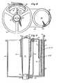
- Fig. 9illustrates blood components as they might occur in an on-going plasmapheresis cycle.
- Processing bag 50contains plasma-poor component, which would typically be packed red cells, indicated by dark stippling, towards its outer radial portion.
- Plasma-rich componentis located radially inwardly and is indicated by light stippling.
- the plasma-rich componentis also shown in tubing 60 and receiver container 61 as it would appear towards the end of a plasmapheresis cycle.
- Plasma-rich componentis expressed from processing bag 50 into receiver container 61 by the action of displacement bag 69 which is partly filled with displacer fluid and has a surface contacting bag 50 so that this surface acts as a fluid-operated diaphram.
- Receiver container 61is provided with a sterile air filter 67 on its top cover to allow any air present in the system to escape.
- Fig. 10illustrates an alternative embodiment in which flexible, disposable blood processing bag 150 is supported by contoured shoe 152 so that bag 150 has an inner surface having a slightly greater slope at its upper portion than at its lower portion. This increased slope provides more efficient emptying during operation.
- Displacer pouch 154is contoured into a complementary shape by support shoe 156. Other elements are the same as previously described. This embodiment permits use of tubing 158, connecting bag 150 to receiver container 61, at the top of bag 150. Thus, support shoe 152 does not have to be split. Displacer pouch 154 can be permanently mounted, if desired, in this or previously described embodiments.
Landscapes
- Health & Medical Sciences (AREA)
- Heart & Thoracic Surgery (AREA)
- Vascular Medicine (AREA)
- Life Sciences & Earth Sciences (AREA)
- Engineering & Computer Science (AREA)
- Anesthesiology (AREA)
- Biomedical Technology (AREA)
- Hematology (AREA)
- Cardiology (AREA)
- Animal Behavior & Ethology (AREA)
- General Health & Medical Sciences (AREA)
- Public Health (AREA)
- Veterinary Medicine (AREA)
- External Artificial Organs (AREA)
- Centrifugal Separators (AREA)
- Medicines Containing Material From Animals Or Micro-Organisms (AREA)
Description
- This invention is in the field of blood processing and more particularly relates to the separation of blood, including whole blood, into two or more components.
- Whole human blood includes at least three types of specialized cells. These are the red blood. cells, white blood cells and platelets. All of these cells are suspended in plasma, a complex aqueous solution of proteins and other molecular substances.
- Until relatively recently, blood transfusions have been given using whole blood. There is, however, growing acceptance within the medical profession for transfusing only those blood components required by a particular patient instead of transfusing whole blood. Transfusing only those blood components necessary preserves the available supply of blood, and in many cases, it is better for the patient. Before blood component transfusions can be widely employed, however, satisfactory blood separation techniques and apparatus must evolve.
- One desirable blood separation is plasmapheresis which is the separation of whole blood into a plasma-rich component and a plasma-poor component. Typically, the plasma-rich component is retained for later use and the plasma-poor component is returned to the donor.
- U.S. Patent No. 3,244,363 to Hein describes a centrifuge apparatus and a flexible, disposable bag therefor for separating a first blood component and a second blood component, the apparatus including a centrifuge having a rotor, said rotor having a blood processing chamber therein for containing the bag and means for rotating the rotor.
- The bag is positioned symmetrically with respect to the axis of rotation of the rotor in use of the apparatus of U.S. Patent No. 3,244,363 and the bag is annularly clamped during rotation physically to separate the plasma-rich and plasma-poor components which are separated subsequent to braking the rotor to a standstill.
- Presently, plasmapheresis is performed on a large scale using satellite pouch systems. A variety of satellite pouch plasmapheresis systems have been patented, and some typical examples are those systems described in U.S. Patent No. 3,190,546 to Raccuglia et al.; U.S. Patent No. 3,211,368 to Shanley; and U.S. Patent No. 3,545,671 to Ross. With such systems, whole blood is withdrawn from a donor and flows to a pouch containing an anti-coagulant. The pouch is then disconnected from the donor phlebotomy line, centrifuged in a swinging bucket type of centrifuge in which cells must travel about half the long dimension of the pouch, typically about 12 cm. The centrifuge must then be gently slowed to a stop and the pouch carefully lifted from the bucket of the centrifuge while avoiding remixing of the two components. The pouch is mounted in a plasma expressor and a supernatant plasma fraction is expressed into a connected plasma pouch, care being given to clamp off the connecting tube between the pouches just before plasma-poor component passes over. The pouch containing the plasma-poor component is then reconnected to the phlebotomy line so that the plasma-poor component can be returned to the donor.
- It has become customary with satellite pouch systems to carry out this sequence of steps twice for each donor. Typically, one unit, or about 500 ml of whole blood is withdrawn, anti- coagulated and separated. Approximately 250 ml of plasma-rich component is obtained and the plasma-poor component is returned to the donor. Subsequently, another unit of whole blood is withdrawn and processed in a similar manner. Using such techniques with satellite pouch systems, it often takes approximately 1-1/2 hours to obtain 500 ml of separated plasma-rich component and to return the plasma-poor component to the donor, even though the time for donating a unit of whole blood is only about 20 minutes. This relatively long processing time imposes a major limitation on volunteer donor recruitment. Additionally, because the blood pouch is disconnected from the donor at the end of each withdraw cycle and transported to and from a separate centrifuge room for centrifugation, there is always the danger of returning blood components to a donor which are not his own. Satellite pouch systems require particularly careful handling of the pouch containing separated plasma-rich and plasma-poor components to avoid remixing thereby ruining the separation.
- Blood cell separation systems, both continuous and intermittent flow, have been placed in widespread use but have not been accepted for widespread application in plasmapheresis because the disposable blood pathways used are too expensive relative to the satellite pouch systems. An example of a recently developed plasmapheresis apparatus is described by Latham in U.S. Patent No. 4,086,924. In this apparatus, whole blood can be withdrawn from a donor using a phlebotomy needle and pressure cuff. The whole blood is anti-coagulated and transported by a blood pump to a plasmapheresis centrifuge where it is separated into plasma-rich and plasma-poor components. Separated plasma-rich component is stored in a plasma container. When a predetermined quantity of separated plasma-rich component has been obtained, cycle control means immediately switch from the withdraw cycle to a return cycle. The cycle control means also immediately switch from the return cycle to either a withdraw cycle or a standby cycle in response to a signal from monitoring means indicating that the return of plasma-poor component has been completed. The manufacturing costs of the disposable blood pathway for this system has been greater than that for a satellite pouch system, however, and although the Latham system is attractive because of the short (30 min.) donor time required, it has involved too much expense to be accepted for use on a wide scale.
- One main reason for the relative!y high expense of the disposable blood pathway in prior blood separation systems of the Latham type relates to the requirement for a specially manufactured blood centrifuge bowl. Many times, for example, parts for these are injection molded from relatively expensive materials, such as polycarbonate, which adds a major element of expense to the disposable blood pathway. Another reason for the relatively high expense in the Latham system is the requirement for precisely manufactured rotary seals to pass blood in and plasma-rich component out of the centrifuge bowl as it is spinning.
- Mitchell et al., in U.S. Patent No. 3,674,197, point out some problems encountered with attempts to use standard flexible blood bags in a centrifuge rotor. The problems mentioned relate to the necessity to properly support the liquid filled bags because they are subjected to various pressures and forces during centrifugation which are not evenly distributed. The shifting of position of the flexible blood bags causes wrinkles and folds in the bag material with consequent imbalancing of the rotor. The Mitchell et al. invention disclosed in this patent relates to contoured shoes which surround a cylindrical flexible blood processing bag to alleviate such problems.
- Another approach to using a flexible blood processing bag in a centrifugation system is disclosed by Jones. et al. in U.S. Patent No. 3,737,096. The highly specialized system disclosed therein is a cell washing system in which a flexible blood bag receives fluid and has fluid withdrawn from it during operation of the centrifuge. The volume of the processing chamber in this centrifuge is adjusted by a flexible membrane connected to a displacement fluid which expands or contracts, respectively, in response to introduction of or withdrawal of a displacement fluid. This system has the disadvantage of requiring a rotary seal. Additionally, the flexible bag is relatively complex.
- As can be appreciated from the above discussion, there has been very considerable effort applied to developing new blood processing systems. Despite this, none of the systems developed heretofore provide the combination of inexpensive disposable blood processing sets, rapid separation, ease of making a fine cut between different blood components and the capability to carry out the entire blood processing immediately adjacent to a blood donor.
- From one aspect the present invention provides an apparatus as described in the fifth paragraph of this description characterised in that the centrifuge is a self-balancing centrifuge having a rotor capable of spinning at speeds sufficient to effect the desired separation without significant concomitant vibration, in that the said blood processing chamber is positioned entirely to one side of the axis of rotation of the rotor and is contoured to support a flexible, disposable blood processing bag with radially inner, and outer wall members of the bag spaced a relatively small distance from one another compared with the internal dimensions of the wall members themselves, and by means for introducing blood to be separated into a flexible, disposable blood processing bag in said chamber, a displacement container having a fluid-operated flexible diaphragm, said displacement container being positioned in the processing chamber whereby the fluid-operated diaphram is positioned to exert pressure on a blood processing bag in said chamber as fluid is introduced into said displacement container thereby to expel first blood component from such blood processing bag into a receiver container while said centrifuge rotor is spinning, and means for introducing displacer fluid into said displacement container thereby to cause said fluid-operated flexible diaphram to exert pressure on a flexible, disposable blood processing bag in said chamber to expel first blood component from such a disposable blood processing bag into a receiver container while the centrifuge is rotatinq.
- In the apparatus of the present invention, the blood processing chamber is ideally designed to support a standard blood bag. The distance that the blood components are required to travel during centrifugation is thereby minimized.
- A self-balancing centrifuge is employed, having a rotor capable of spinning at. speeds sufficient to effect the desired separation without significant concomitant vibration, because imbalanced masses of blood components and displacer fluid are introduced or withdrawn during use of the apparatus which would render a conventional centrifuge useless for separation.
- After separation of a desired amount of first blood component, the rotor is stopped and any changes in the blood pathway required for return of second blood component to donor are made. Second blood component can then be returned by introducing more displacement fluid into the displacement chamber. After second component has been returned, additional blood to be separated can be introduced into the flexible blood processing bag thereby forcing displacement fluid from the displacement chamber. The separation procedures can then be repeated.
- The present invention further provides a disposable blood pathway for use with an apparatus of the present invention as hereinbefore defined including a flexible blood processing bag having at least one inlet port and one outlet port and a pair of opposite wall members spaced a relatively small distance from one another compared with the internal dimensions of the wall members themselves, a receiver container for receiving first blood component separated in said flexible blood processing bag, said receiver container having at least one inlet port and a sterile air vent, blood-compatible tubing connecting an outlet port of said flexible blood processing bag with an inlet port of said receiver container, and blood-compatible tubing for providing fluid communication between a source of blood to be separated and an inlet port on said flexible blood processing bag.
- This completely disposable, blood pathway, including the blood processing bag is relatively inexpensive.
- The apparatus of the present invention is extremely versatile and can be used in a great many applications where it is desirable to separate one or more components from blood, including separations requiring precise cuts between centrifugally separated fractions. Additionally, these separations can be done quickly with the apparatus stationed next to a blood donor since the apparatus can be made quite small and light in weight. This apparatus also provides the capability of separating blood cells without subjecting them to the trauma associated with intense mechanical shear experienced in conventional rotary seal machines and in the more recently developed machines which eliminate the need for a rotary seal by employing a rapidly flexing umbilical cable to pass fluids to and from a centrifuge rotor. The ease with which the operating technician can observe progress of the separation process and the accuracy of controlling making product cuts is also an advantage. Additionally, there is less platelet activation, less particulate contamination possible, and less anti-coagulant required with the apparatus of the invention.
- The present invention includes a method of centrifugally separating into a first blood component and a second blood component blood contained within a flexible blood processing bag having a pair of opposite wall members spaced a relatively small distance from one another compared with the internal dimensions of the wall members themselves, the method comprising mounting the bag in a centrifuge rotor with its said wall members radially spaced from the axis of rotation of the rotor so that said second blood component will be forced radially outward during centrifugal separation toward a radially outer one of said bag wall members, rotating said centrifuge rotor at a speed sufficient to cause said second blood component to travel radially outwards towards the radially outer one of said bag wall members, thereby causing first blood component to collect near the opposite, radially inner one of said bag wall members, and then partially collapsing said bag by applying pressure to an external surface thereof thereby to expel first blood component from said bag and into a receiver container within said centrifuge rotor.
- Some ways of carrying out the invention in all its aspects are described below with reference to drawings which illustrate two specific embodiments. In the drawings:
- Fig. 1 is a diagrammatic illustration of an apparatus according to this invention in use in combination with a disposable blood pathway of this invention for plasmapheresis;
- Fig. 2 is a diagrammatic view of the whole of the disposable blood pathway according to this invention used in Fig. 1;
- Fig. 3 is a perspective view of the flexible, disposable, blood processing bag of the pathway;
- Fig. 4 is a perspective view of a flexible fluid bag suitable for use as a displacement pouch in the apparatus of Fig. 1;
- Fig. 5 is a perspective view of complementary support shoes for the blood processing bag and displacement pouch of Figs. 3 and 4, respectively used in the apparatus of Fig. 1;
- Fig. 6 is a perspective view of a holder for the support shoes of Fig. 5 used in the apparatus of Fig. 1;
- Fig. 7 is a partially cut-away front elevational view of a self-balancing centrifuge suitable for use in the apparatus of Fig. 1;
- Fig. 8 is a plan view of the centrifuge of Fig. 7;
- Fig. 9 is a partially cut-away side elevational view of the centrifuge rotor with a portion of the disposable blood pathway shown in Fig. 2 contained therein; and
- Fig. 10 is a partially cut-away side elevational view of a centrifuge rotor containing a blood processing bag having an alternative geometry together with a complementary displacement bag and a receiver container.
- As used herein, the following terms are defined to mean:
- "Self-balancing centrifuge"-a centrifuge which is designed so that once the rotor has surpassed a minimum in rotational velocity, the rotor will spin around its angular momentum axis rather than its geometrical axis of symmetry. Thus, disruptive vibrations from an unbalanced rotor, which would create intolerable vibrations in a conventional centrifuge, are not generated.
- "First blood component"--one desired fraction of blood which has been separated from or which it is desired to separate from another fraction;
- "Second blood component"-another fraction separated from blood which is the balance after first blood component has been separated therefrom;
- "Plasma-rich component"-a fraction of blood which is richer in plasma than whole blood;
- "Plasma-poor component"-a fraction of blood which is poorer in plasma than whole blood.
- The figures show a plasmapheresis separation with reference to Fig. 1, which is a diagrammatic illustration of
plasmapheresis apparatus 10, and Figs. 2 to 9, illustrate components of theplasmapheresis apparatus 10 in more detail. - To withdraw whole blood from donor's
arm 12, astandard phlebotomy needle 16 can be used with this apparatus.Phlebotomy needle 16 might be, for example, a 15-gauge, thin wall phlebotomy needle of the type which has a supply of anti-coagulant connected to it so that freshly withdrawn blood is anticoagulated as soon as it leaves the needle. A particularly suitable phlebotomy needle of this type is described in detail in U.S. Patent No. 3,916,892 issued to Latham. - Anti-coagulant is supplied from anti-coagulant pouch 18 to
phlebotomy needle 16 throughanti-coagulant tubing 20 which is connected throughtransparent drip chamber 22 and spike 23 to pouch 18.Transparent drip chamber 22 allows the operator to observe anti-coagulant flow.Pump 24 provides anti-coagulant pumping, when necessary, and is a roller-type pump having amovable platen 26 which is employed to clampblood tubing 20 against rollers 25. Roller pumps of this type are described in detail in U.S. Patent No. 3,565,286, also issued to Latham. - Prior to making the venipuncture, the disposable set of software is mounted in the permanent components of
apparatus 10. Anti-coagulant pouch 18 is connected by insertion ofspike 23 in the conventional manner whilepump platen 26 is clamped againsttubing 20.Drip chamber 22 is squeezed slightly to expel some of its contained air into anti-coagulant pouch 18 and then released so that a small pool of anti-coagulant accumulates in the lower portion ofdrip chamber 22. Blood processing bag 50 is completely collapsed by passing as much displacer fluid intopouch 69 as possible. Clamp 142 (Fig. 8) is then closed to isolateblood processing bag 50 fromcomponent receiver container 61.Anti-coagulant tubing 20 andblood tubing 28 are primed with anti-coagulant by releasingpump platen 26 to allow gravity flow of anti-coagulant through these lines until a small quantity collects inmonitor pouch 30.Pump platen 26 is then reclamped. Throughout this priming procedure the small pool of anti-coagulant in the lower section ofdrip chamber 22 serves to prevent entrainment of air bubbles in the stream of anti-coagulant enteringtubing 20 thereby assuring an air-free primed condition. Also, the operator is able to visualize the rate of anti-coagulant flow through the air space in the upper portion ofdrip chamber 22 and thereby verify that approximately the correct anti-coagulant flow is occurring at all times.- The site where the venipuncture is to be made is then prepared. After preparation,
pressure cuff 27 is fastened around donor'sarm 12 at a location above wherephlebotomy needle 16 is to be inserted. Pressurizing gas is supplied to pressurecuff 27 from a gas canister (not shown), and the precise pressure applied is usually regulated by a pressure regulator. A gas valve may also be provided which has an open and a relief position, the latter being provided to release pressure inpressure cuff 27. A typical pressure is about 50 mm Hg which raises the pressure in the donor's veins sufficiently to facilitate the venipuncture and to boost fluid flow from the donor's veins. Plasmapheresis apparatus 10 is now started by energizing electrical systems to control pump motors, activate detectors,control pressure cuff 27, etc. Control logic may be used to monitor and control the overall operation of the plasmapheresis apparatus, if desired.- The venipuncture is then made by inserting
phlebotomy needle 16 into a vein in donor'sarm 12 at the previously prepared site. Freshly withdrawn, anticoagulated, whole blood flows under venipressure from the donor through blood-compatible tubing 28 intomonitor pouch 30.Monitor pouch 30 can have either aweight detector 32 or apressure detector 34 associated with it, or both. Weight detection can be used to sense the weight of blood which is present in the monitor pouch at any given time. This in turn can be used to both activate and control the speed ofblood pump 36, which is also a roller-type pump having rollers 37 and amovable platen 38. The function ofpressure detector 34 will be described in conjunction with the return cycle. - At the start of a withdraw cycle, monitor
pouch 30 is empty insofar as blood and blood components are concerned. As blood entersmonitor pouch 30, its weight eventually reaches a threshold value which is sensed byweight detector 32. At this threshold weight, an appropriate signal is transmitted to actuate rollers 37 inblood pump 36 and to actuate rollers 25 inanti-coagulant pump 24.Blood pump 36 preferably has at least two speeds, and these speeds are determined byspeed controller 39 acting in response to the signals received fromweight detector 32. If the blood flow fromphlebotomy needle 16 is greater than that toblood pump 36, monitorpouch 30 fills thereby becoming heavier and causingweight detector 32 to transmit signals to speedcontroller 39 to advanceblood pump 36 to a higher speed position. If, on the other hand, blood flow fromphlebotomy needle 16 is less than that toblood pump 36, monitorpouch 30 begins to empty thereby losing weight and causing signals to be transmitted to speedcontroller 39 to returnpump 36 to a lower speed position. Ifmonitor pouch 30 continues to lose weight even at the lower pump speed, a signal can likewise be transmitted to causeblood pump 36 to operate at a still lower speed, if available, or to be shut off entirely untilmonitor pouch 30 fills once again. In this way, blood is pumped frommonitor pouch 30 but never from the donor. This pattern of action continues through a withdraw cycle. - Anti-coagulated whole blood is pumped from
monitor pouch 30 through bloodcompatible tubing 41 to a firstU-shaped flow divider 42 havinglegs 43 and 44 (Fig. 2).Leg 44 is connected bytubing 45 to aspike port 46, but flow is prevented along this path at this time byclamp 47 which is closed. Whole blood does flow throughleg 43 and blood-compatible tubing 48 to second U-shaped flow divider 42' having legs 43' and 44'. Leg 44' is connected by blood compatible tubing 45' to a spike port 46'. Tubing 45' is clamped off at this point in the procedure by clamp 47' so that anti-coagulated whole blood flows along leg 43' andtubing 49 toblood processing bag 50. Blood processing bag 50 can be seen in more detail in Fig. 3. Therein, it can be seen that flexible, disposableblood processing bag 50 has a front, planar, generally-rectangular wall member orpanel 52. There is also a back, matching planar, generally-rectangular wall member orpanel 52, which cannot be seen, and the front and back panels are sealed together around theperiphery 54 ofbag 50 with a fluid-tight seal. A pattern ofholes 55 is provided in sealedperiphery 54 to help in registeringblood processing bag 50 in its proper location within contoured shoes which are described below.Blood processing bag 50 has three fluid ports, 56, 57 and 58, located at its top, and afluid port 59 located approximately in the centre offront panel 52. Blood-compatible tubing 60 extends fromport 59 and is connected toreceiver container 61 atentry port 62. Thereceiver container 61 can be a blow-molded container formed as a volume of revolution with its upper end larger than its lower end.Inlet port 62 is located at a point of substantially maximum diameter ofreceiver container 61 so that material can be withdrawn fromcontainer 61 back intoblood processing pouch 50, if desired.Receiver container 61 is also provided withtop flaps bottom flap 65, each having holes therein, so thatcontainer 61 can be conveniently hung from its top or bottom. Of course, these flaps are optional and may be omitted or replaced with spike ports, etc.Receiver container 61 additionally has asterile air filter 67 which allows any air contained within the system to pass therethrough. Other receiver container geometries can be employed, of course, with any geometry designed to minimize rotor imbalance as first blood component is introduced being preferred.- Fig. 4 illustrates a flexible displacement container or
pouch 69 inplasmapheresis apparatus 10. Flexible,displacement pouch 69 is a flexible liquid bag formed from planar front and back panels one of which forms a fluid operated diaphragm 69' (see figs 9 and 10) and having aperipheral seal 70. Registration holes 71 are provided in theperipheral seal 70 and a single inlet/outlet port 72 is provided at the bottom to allow displacer fluid to be transported into or out ofpouch 69 viadisplacer fluid tubing 73. Blood processing bag 50 andflexible displacement pouch 69 are held in a complementary relationship in a contoured processing chamber 200 (see figs 9 and 10) formed between a pair of support shoes which are shown in Fig. 5.Shoe 74 has aninner surface 75 having a generally cylindrical shape approximately concentric with the geometrical axis of rotation.Inner surface 75 contacts the radially outward face ofpouch 69 during processing.Channel 76 is provided inshoe 74 to allowdisplacer fluid tubing 73 to pass through the support shoes when they are held in their closed position. A pattern ofpegs 77 is provided around the edge ofsupport shoe 74, and the function ofpegs 77 is described below.Support shoe 78 is actually split into upper shoe half 78a and lower shoe half 78b, to allowtubing 60 to be inserted throughhole 79 ofshoe 78. This is necessary because the entire blood pathway, as illustrated in Fig. 2, is integral and disposable. Peg holes 80 are provided around the inner edge ofshoe 78 to accommodatepegs 77 located around the inner edge ofsupport shoe 74.Inner surface 81 ofshoe 78 has a somewhat cylindrical contour, but is additionally contoured to have a gentle slope from both its top and bottom towards a horizontal centre line passing throughhole 79 and is also contoured to have a gentle slope from both sides towards a vertical centre line passing throughhole 79. Such contoured sloping provides a centrifugal slope from all points so that separated first blood component is always directed towardsoutlet 59 ofblood processing pouch 50 during centrifugation.Channels shoes Channels tubing support shoes tubing - Support shoes 74 and 78 can be formed from polymers such as foamed polyurethane. In some cases, it will be preferred to have transparent support shoes, in which case they can be formed from transparent polymers, such as poly(methylmethacrylate). Many other materials could be used in forming these support shoes, of course.
Pouch 69 is mounted onshoe 74 by insertingpegs 77 throughregistration holes 71 in theperipheral seal 70 ofpouch 69; subsequently, processingbag 50 is mounted onpegs 77 in the same manner employingregistration holes 55 while ensuring that itsport 59 is positioned radially inwardly.Shoes holes 80 in the edge ofshoe 78. In their closed position, shoes 74 and 78 form an enclosed contoured processing chamber containingblood processing bag 50 andfluid displacer pouch 69, which are positioned so that their contacting planar panels assume a complementary relationship.- When
blood processing bag 50 andflexible pouch 69 are positioned in this complementary relationship within the contoured processing chamber formed betweensupport shoes pouch 69, the pouch expands to force blood or blood components out of processingbag 50. Similarly, as anti-coagulated whole blood passes intoblood processing bag 50 under positive pressure, an equal volume of displacer fluid is forced from theflexible displacement pouch 69. - The basic shape of the contoured
processing chamber 200 is an arc of a cylindrical annulus approximately concentric with the axis of rotation. The radial thickness of this chamber is minimized, and is preferably less than 15% of the peripheral length of the arc. The contour of the wall of the chamber on the side nearest the axis of rotation is modified from a true arc about this axis to provide a slope for natural drainage within the centrifugal field of the less dense plasma-rich component towardoutlet port 59 located in the centre of the radially inner face ofblood processing bag 50. This is achieved by the centrifugal slope provided by the contouredsurface 81 ofsupport shoe 78. - Support shoes 74 and 78 are held in a closed position by placing them in a
support shoe holder 85 illustrated in Fig. 6.Holder 85 has a cylindrically shapedback wall 86, two side walls, 87 and 88, each of which has acurved lip 89 at its terminal portion which curls around to containsupport shoes Holder 85 is also provided with ahandle 90 so that it can be conveniently lifted.Support shoe holder 85 can be formed from materials such as aluminium, etc. - A plasmapheresis
procedure employing apparatus 10 is as follows. Prior to withdrawing blood from donor'sarm 12,blood processing bag 50 is collapsed by fillingpouch 69 completely with displacer fluid whiletube 60 is tightly clamped. The displacer fluid distendsbag 69, which in turn compressesprocessing bag 50 againstinner surface 81 ofshoe 78 to express any blood or blood components frombag 50. - Use of a fixed charge of displacer fluid passing in
tubing 92 between a stationarydisplacer fluid station 93, external tocentrifuge rotor 94, anddisplacer pouch 69 withinrotor 94, allows the monitoring of the volume of blood introduced intoblood processing bag 50 since the total volume of the displacer pouch and blood processing bag is constant. Thus, the amount of blood or components inblood processing bag 50 can be accurately determined by monitoring either changes in weight or volume of displacement fluid indisplacer station 93. - When the desired amount of whole blood has withdrawn from a donor, blood
compatible tubing 49 is first sealed, such as can be done with a dielectric sealer, and then cut. This is typically done by sealingtubing 49 in two places and by cutting between the seals or by making a broad seal which is cut in the middle.Anti-coagulant pump 24 continues to slowly pump anti-coagulant throughphlebotomy needle 16 at this point to prevent clot formation therein while blood is not flowing. Centrifuge motor 102 is now activated to causecentrifuge rotor 94 to rotate at a speed sufficient to separate the withdrawn whole blood contained inprocessing bag 50 into a plasma-rich component and a plasma-poor component. A typical rotor speed, for example, might be about 4800 rpm.- As
centrifuge rotor 94 rotates, plasma-poor component, which in this case consists primarily of red blood cells, white blood cells and platelets, moves towards the radially outer face of disposableblood processing bag 50. This creates plasma-rich component near the radially inner face, and this can be expressed fromdisposable processing bag 50 ascentrifuge rotor 94 spins by introducing displacer fluid intodisplacement pouch 69 thereby applying pressure to disposableblood processing bag 50. Plasma-rich component is expressed throughcentral port 59 of the flexibleblood processing bag 50 and is transported intubing 60 toreceiver container 61 asrotor 94 continues spinning to obtain further separation.Tubing 60 is preferably kept relatively short to prevent it from folding back upon itself when the software is positioned in the centrifuge rotor. - Whenever plasma-rich component is being expressed from
blood processing bag 50, tube clamp 142 (Fig. 8) is released to permit flow throughtubing 60 toreceiver container 61. At all other times,clamp 142 is kept closed. Since the inlet forreceiver container 61 is positioned at a point of maximum diameter it is possible to withdraw material fromreceiver container 61 back intoblood processing pouch 50 by withdrawing displacer fluid fromdisplacement pouch 69 whileclamp 142 is open. This operates as a safeguard in case material is expressed fromblood processing pouch 50 beyond that where the cut is desired. An optical detector can be provided, if desired, to sense when the separation has been completed.Clamp 142 is hydraulically operated by fluid contained inhydraulic fluid reservoir 95 and supplied inline 97. - When the cut has been completed,
centrifuge rotor 94 is braked to a stop. A protective cover, if present, is removed from bag spike 46' and also fromspike port 56 inblood processing bag 50. Slide clamp 47' on bag spike 46' is opened just long enough to allow spike 46' to prime with blood from blood tubing 45'. At this point, spike 46' is inserted intospike port 56 at the top of flexible, disposableblood processing bag 50 and slide clamp 47' is fully opened. - Plasma-poor component can now be returned to the donor by opening
blood pump platen 38, and introducing displacer fluid intodisplacement pouch 69. Dlsplacer fluid is transported topouch 69 until it is once again filled with displacer fluid indicating that all of the plasma-poor component has been returned to the donor. This can be determined by measuring the amount of displacer fluid transported fromstationary displacement station 93. - In the return cycle, monitor
pouch 30 fills with plasma-poor component.Pressure detector 34 senses any undesirable build-ups of pressure in the system, which might be caused, for example, by a restriction at the tip ofphlebotomy needle 16. When such a buildup is sensed, an appropriate signal can be transmitted to slow or halt the transport of displacer fluid topouch 69. Optionally, an audible or visual alarm may be given. - When the plasma-poor component has been returned to the donor, a second whole blood withdrawal can be initiated. This can be done similarly to the first withdrawal cycle, except that the whole blood now flows through spike port 46' and into the top of disposable, flexible
blood processing pouch 50 throughport 56. After the desired amount of anti-coagulated whole blood has been introduced into disposable, flexibleblood processing bag 50, blood compatible tubing 45' is sealed and cut, as before. Processing can now commence in a manner similar to that previously described. - At the end of the separation,
centrifuge rotor 94 is stopped, the protective covers frombag spike 46 and spikeport 58 are removed,slide clamp 47 is opened just long enough to allowspike 46 to prime with blood, and then spike 46 is inserted intospike port 58.Slide clamp 47 is fully opened and plasma-poor component remaining in flexible, disposableblood processing pouch 50 is returned to the donor, as before. - In a typical plasmapheresis separation as described, 500 ml of whole blood can be withdrawn in each withdrawal cycle. Each centrifuge cycle can produce about 250 ml of plasma-rich component having a small amount of anti-coagulant therein. This plasma-rich component is essentially free of other components. The plasma-poor component can be returned to the donor and would typically consist of something like about 84% red blood cells, 1% platelets and about 15% plasma-it would also contain a small amount of anti-coagulant. Thus, after two withdraw cycles of 500 ml of whole blood each, and two separation and return cycles, approximately 500 ml of plasma remain in the plasma receiver. The time for carrying out the entire procedure is likely to be thirty minutes or less.
- Imbalance in
centrifuge rotor 94 is minimized even though fluid is being introduced and withdrawn during its operation, since the total volume of fluid, within the asymmetric portion of the fluid pathway, namely blood plus displacer fluid, remans constant. To further minimize imbalance, it is preferable to employ displacer fluid having a density close to that of whole blood, such as within ±15% of the density of whole blood. It is further preferred, ifdisplacer pouch 69 is located radially outwardly, to employ displacer fluid having a density greater than that of the second blood component-this helps to maintain a generally cylindrical interface between thedisplacer pouch 69 andblood processing bag 50 and minimizes any tendency for theprocessing bag 50 to be pinched off during return of second blood component to a donor. As an example, in a plasmapheresis separation, a displacer fluid density of about 1.1 would be suitable since typical specific densities for whole blood, packed cells and plasma are approximately 1.06, 1.09 and 1.05 respectively. On the other hand, it might be desirable in some cases to locate the displacement pouch on the radially inner side of a blood processing bag, in which case it would be preferred to employ displacer fluid with a density lower than the lightest blood component formed during separation. - The shape of
receiver container 61 and its positioning withinrotor 94 also minimize imbalance in the centrifuge. As can be seen, fluid present inreceiver container 61 whilerotor 94 is spinning is evenly distributed about the axis of rotation. Other receiving containers for a separated blood component can be used, of course, but it is preferable to employ one or more receiver containers which attain a substantially even distribution of fluid therein about the axis of rotation. - It is preferable to employ blood-compatible materials for all tubing, pouches, bags, etc., in this apparatus if they come into contact with blood or a component thereof. An example of such a material is polyethylene. In some cases, such as those where tubing is cut and sealed, it is particularly preferred to employ a blood-compatible, heat-sealable material, such as poly(vinyl chloride). It is also preferable, in many cases, to form pouches and bags from transparent materials to permit visibility during processing.
- One self-balancing centrifuge suitable for use in the invention described herein is illustrated in more detail in Figs. 7 to 9. Therein,
centrifuge 100 can be driven by a standardelectric motor 102, which may be fixed or variable speed. Preferably,motor 102 is vibration isolated and mounted to a rigid structure through mountingplate 103. Drivepulley 104, attached tomotor drive shaft 105, drives centrifuge drivepulley 106 viadrive belt 107. - A pivot mount is positioned in the plane of
pulleys belt 107 to eliminate significant turning moments in planes coincident with the axis of rotation. A suitable pivot mount can be formed from anelastomeric ring 110 of soft silicone rubber or other similar material mounted within an outer metallic ring member 111 attached tostationary mount 113 and an innermetallic ring member 115 attached tostationary housing 117. This pivot mount allowscentrifuge 100 to find its own axis or centre of rotation around its angular momentum axis or vector, while still providing some resistance to undesired movement ofcentrifuge shaft 112. - The bottom end of
centrifuge shaft 112 is journalled inradial ball bearings 114.Shaft 112 is a thin walled tube with good stiffness but one which is light in weight, such as can be formed from stainless steel tubing.Rotary seals metallic fluid lines flexible tubing - An oiled
porous bearing 120 acts as a damped, resilient restraining mount employed near the top ofshaft 112 to provide a slight righting force. Bearing 120 is formed byinner ring member 123 andouter ring member 125 withspongy elastomer material 124 therebetween.Outer ring member 125 is rigidly secured to support 122.Elastomeric material 124 acts as a light spring and damper, and allows the spring constant and damping to be independently controlled. Open cell elastomeric foam is preferred. Receiver container 61 is located withincentrifuge rotor 94 in taperedconical holder 126.Rotor 94 can be formed from aluminium and may be provided with a protective polymethyl methacrylate guard. Access torotor 94 is conveniently provided through its top.- An optical slit (not shown) positioned directly beneath
tubing 60 and a strong projection lamp secured in a stationary location underrotor 94 may be used to provide synchronized illumination oftubing 60. Alternatively, a synchronized stroboscopic light may be used to illuminate the entire interior ofrotor 94. - Displacer fluid at
station 93 can be stored in a transparentgraduated reservoir 130 which facilitates measurements of the amount present. It is transported todisplacer pouch 69 inmetal tubing 92 andflexible tubing 134 which are coupled atrotary seal 116.Flexible tubing 134 runs up throughshaft 112 todisplacement pouch 69. Displacerfluid pump 136 is used to transport displacer fluid fromreservoir 130 todisplacer pouch 69. The return of displacer fluid is achieved by inactivatingpump 136 and opening solenoid valve 140 in by-pass line 138 wherebyblood filling bag 50 operates to force displacer fluid frompouch 69 and back toreservoir 130 throughlines - Hydraulically actuated
clamp 142 is connected byflexible tubing 144 andrigid tubing 94, coupled throughrotary seal 118, to hydraulicfluid cylinder 148. Hydraulic pressure is applied bypiston 150 which can be operated in the forward direction bysolenoid 152 and in the return direction byspring 154. - Fig. 9 illustrates blood components as they might occur in an on-going plasmapheresis cycle. Processing
bag 50 contains plasma-poor component, which would typically be packed red cells, indicated by dark stippling, towards its outer radial portion. Plasma-rich component is located radially inwardly and is indicated by light stippling. The plasma-rich component is also shown intubing 60 andreceiver container 61 as it would appear towards the end of a plasmapheresis cycle. - Plasma-rich component is expressed from processing
bag 50 intoreceiver container 61 by the action ofdisplacement bag 69 which is partly filled with displacer fluid and has asurface contacting bag 50 so that this surface acts as a fluid-operated diaphram.Receiver container 61 is provided with asterile air filter 67 on its top cover to allow any air present in the system to escape. - Fig. 10 illustrates an alternative embodiment in which flexible, disposable
blood processing bag 150 is supported bycontoured shoe 152 so thatbag 150 has an inner surface having a slightly greater slope at its upper portion than at its lower portion. This increased slope provides more efficient emptying during operation.Displacer pouch 154 is contoured into a complementary shape bysupport shoe 156. Other elements are the same as previously described. This embodiment permits use oftubing 158, connectingbag 150 toreceiver container 61, at the top ofbag 150. Thus,support shoe 152 does not have to be split.Displacer pouch 154 can be permanently mounted, if desired, in this or previously described embodiments.
Claims (28)
Applications Claiming Priority (2)
| Application Number | Priority Date | Filing Date | Title |
|---|---|---|---|
| US06/005,126US4303193A (en) | 1979-01-22 | 1979-01-22 | Apparatus for separating blood into components thereof |
| US5126 | 1979-01-22 |
Publications (2)
| Publication Number | Publication Date |
|---|---|
| EP0014093A1 EP0014093A1 (en) | 1980-08-06 |
| EP0014093B1true EP0014093B1 (en) | 1983-05-04 |
Family
ID=21714313
Family Applications (2)
| Application Number | Title | Priority Date | Filing Date |
|---|---|---|---|
| EP80300198AExpiredEP0014093B1 (en) | 1979-01-22 | 1980-01-22 | An apparatus, a method and a disposable blood pathway for use in separating blood into components thereof |
| EP80900294AWithdrawnEP0023220A1 (en) | 1979-01-22 | 1980-07-29 | Apparatus for separating blood into components thereof |
Family Applications After (1)
| Application Number | Title | Priority Date | Filing Date |
|---|---|---|---|
| EP80900294AWithdrawnEP0023220A1 (en) | 1979-01-22 | 1980-07-29 | Apparatus for separating blood into components thereof |
Country Status (7)
| Country | Link |
|---|---|
| US (1) | US4303193A (en) |
| EP (2) | EP0014093B1 (en) |
| JP (1) | JPS55501133A (en) |
| CA (1) | CA1147308A (en) |
| DE (1) | DE3062915D1 (en) |
| NO (2) | NO802773L (en) |
| WO (1) | WO1980001470A1 (en) |
Cited By (3)
| Publication number | Priority date | Publication date | Assignee | Title |
|---|---|---|---|---|
| US9028388B2 (en) | 2010-06-07 | 2015-05-12 | Terumo Bct, Inc. | Multi-unit blood processor with volume prediction |
| US9687598B2 (en) | 2010-05-27 | 2017-06-27 | Terumo Bct, Inc. | Multi-unit blood processor with temperature sensing |
| US9733805B2 (en) | 2012-06-26 | 2017-08-15 | Terumo Bct, Inc. | Generating procedures for entering data prior to separating a liquid into components |
Families Citing this family (147)
| Publication number | Priority date | Publication date | Assignee | Title |
|---|---|---|---|---|
| EP0026417B1 (en)* | 1979-09-22 | 1983-12-14 | Firma Andreas Hettich | Centrifuge with system of bloodbag for the separation of blood components |
| US4304357A (en)* | 1980-06-16 | 1981-12-08 | Haemonetics Corporation | Blood processing centrifuge |
| DE3125832C2 (en)* | 1981-07-01 | 1985-07-25 | Westfalia Separator Ag, 4740 Oelde | Centrifuge with a drive with a vertical spindle |
| AU8565682A (en)* | 1981-07-09 | 1983-01-13 | Haemonetics Corporation | Centrifugal blood fractionation |
| USD274646S (en) | 1982-02-08 | 1984-07-10 | Baxter Travenol Laboratories, Inc. | Plasmapheresis and fluid exchange device |
| USD274751S (en) | 1982-02-08 | 1984-07-17 | Baxter Travenol Laboratories, Inc. | Plasmapheresis and fluid exchange device |
| USD296821S (en) | 1983-12-02 | 1988-07-19 | Gambro Lundia Ab | Control device for medical treatment |
| GB8521867D0 (en)* | 1985-09-03 | 1985-10-09 | Fisons Plc | Centrifuge |
| EP0587257B1 (en)* | 1985-09-10 | 1998-06-10 | Vereniging Het Nederlands Kanker Instituut | Method and device for preventing imbalance during the separation and isolation of blood or bone marrow components |
| SE8601891D0 (en)* | 1986-04-24 | 1986-04-24 | Svante Jonsson | PLASMA SWITCH TREATMENT AND TROMBOCYTING MACHINE |
| DE3786263T2 (en)* | 1986-05-16 | 1994-01-05 | Omega Medicinteknik Ab | Device for plasmaphoresis. |
| US4668214A (en)* | 1986-06-09 | 1987-05-26 | Electromedics, Inc. | Method of washing red blood cells |
| US4965846A (en)* | 1986-08-11 | 1990-10-23 | Baxter International Inc. | Pivot pin bearing/seal with loose eyelet especially suited for disposable continuous flow blood filtration system cartridges |
| US4714457A (en)* | 1986-09-15 | 1987-12-22 | Robert Alterbaum | Method and apparatus for use in preparation of fibrinogen from a patient's blood |
| DE3632176A1 (en)* | 1986-09-22 | 1988-04-07 | Fresenius Ag | CONTROL OF A SYSTEM FOR SEPARATING THE COMPONENTS OF BLOOD TAKEN FROM A DONOR "IN VIVO" |
| US5076911A (en)* | 1987-01-30 | 1991-12-31 | Baxter International Inc. | Centrifugation chamber having an interface detection surface |
| US4806252A (en)* | 1987-01-30 | 1989-02-21 | Baxter International Inc. | Plasma collection set and method |
| US6780333B1 (en) | 1987-01-30 | 2004-08-24 | Baxter International Inc. | Centrifugation pheresis method |
| US4834890A (en)* | 1987-01-30 | 1989-05-30 | Baxter International Inc. | Centrifugation pheresis system |
| US5104526A (en)* | 1987-01-30 | 1992-04-14 | Baxter International Inc. | Centrifugation system having an interface detection system |
| US4940543A (en)* | 1987-01-30 | 1990-07-10 | Baxter International Inc. | Plasma collection set |
| US4769001A (en)* | 1987-02-25 | 1988-09-06 | Baxter International Inc. | Method and apparatus for calibrating plural pump fluid flow system |
| DE3723092C1 (en)* | 1987-07-13 | 1989-01-26 | Westfalia Separator Ag | Continuous centrifuge for the industrial production of proteins from human blood plasma |
| US4889524A (en)* | 1987-09-04 | 1989-12-26 | Haemonetics Corporation | Portable centrifuge apparatus |
| US4936820A (en)* | 1988-10-07 | 1990-06-26 | Baxter International Inc. | High volume centrifugal fluid processing system and method for cultured cell suspensions and the like |
| US5078671A (en)* | 1988-10-07 | 1992-01-07 | Baxter International Inc. | Centrifugal fluid processing system and method |
| US4921473A (en)* | 1989-02-02 | 1990-05-01 | Therakos, Inc. | Multicomponent fluid separation and irradiation system |
| SE9002255D0 (en)* | 1990-06-26 | 1990-06-26 | Eric Westberg | METHOD AND APPARATUS FOR THE PREPARATION OF BLOOD |
| JP3231086B2 (en)* | 1992-06-30 | 2001-11-19 | テルモ株式会社 | Liquid separation device |
| PL307164A1 (en) | 1992-07-13 | 1995-05-02 | Pall Corp | Automatic system for and method of processing biological fluids |
| IT1260685B (en)* | 1993-09-29 | 1996-04-22 | Sorin Biomedica Spa | BLOOD CONTAINMENT DEVICE |
| DK0743949T3 (en) | 1994-02-07 | 2000-04-10 | Qiagen Gmbh | Process for the preparation of endotoxin-free or endotoxin-low nucleic acids and / or oligonucleotides for gentera |
| US7332125B2 (en)* | 1994-10-13 | 2008-02-19 | Haemonetics Corporation | System and method for processing blood |
| US5733253A (en)* | 1994-10-13 | 1998-03-31 | Transfusion Technologies Corporation | Fluid separation system |
| US5651766A (en) | 1995-06-07 | 1997-07-29 | Transfusion Technologies Corporation | Blood collection and separation system |
| US5566919A (en)* | 1994-10-13 | 1996-10-22 | Norfolk Scientific, Inc. | Motor mount for reducing vibration and noise and method of using thereof |
| US6632191B1 (en) | 1994-10-13 | 2003-10-14 | Haemonetics Corporation | System and method for separating blood components |
| US5585007A (en)* | 1994-12-07 | 1996-12-17 | Plasmaseal Corporation | Plasma concentrate and tissue sealant methods and apparatuses for making concentrated plasma and/or tissue sealant |
| US5722946A (en)* | 1995-06-07 | 1998-03-03 | Cobe Laboratories, Inc. | Extracorporeal blood processing methods and apparatus |
| US5702357A (en) | 1995-06-07 | 1997-12-30 | Cobe Laboratories, Inc. | Extracorporeal blood processing methods and apparatus |
| US5720716A (en)* | 1995-06-07 | 1998-02-24 | Cobe Laboratories, Inc. | Extracorporeal blood processing methods and apparatus |
| US5795317A (en)* | 1995-06-07 | 1998-08-18 | Cobe Laboratories, Inc. | Extracorporeal blood processing methods and apparatus |
| US5676644A (en)* | 1995-06-07 | 1997-10-14 | Cobe Laboratories, Inc. | Extracorporeal blood processing methods and apparatus |
| AU718172B2 (en)* | 1995-06-07 | 2000-04-06 | Haemonetics Corporation | Method of collecting and processing blood |
| US5750025A (en)* | 1995-06-07 | 1998-05-12 | Cobe Laboratories, Inc. | Disposable for an apheresis system with a contoured support |
| US6790195B2 (en) | 1995-06-07 | 2004-09-14 | Gambro Inc | Extracorporeal blood processing methods and apparatus |
| US5837150A (en)* | 1995-06-07 | 1998-11-17 | Cobe Laboratories, Inc. | Extracorporeal blood processing methods |
| US5738644A (en) | 1995-06-07 | 1998-04-14 | Cobe Laboratories, Inc. | Extracorporeal blood processing methods and apparatus |
| BR9609395A (en)* | 1995-06-07 | 1999-06-15 | Cobe Lab | Extracorporeal blood processing processes and apparatus |
| US6140040A (en)* | 1995-10-06 | 2000-10-31 | Advanced Minerals Corporation | Method of mechanically separating microparticles suspended in fluids using particulate media |
| US6123655A (en)* | 1996-04-24 | 2000-09-26 | Fell; Claude | Cell separation system with variable size chamber for the processing of biological fluids |
| DE19746914C2 (en) | 1996-10-25 | 1999-07-22 | Peter Dr Geigle | Centrifugation unit |
| SE9700495D0 (en) | 1997-02-12 | 1997-02-12 | Omega Medicinteknik Ab | Method and round bag system and centrifuge for blood treatment |
| US6200287B1 (en) | 1997-09-05 | 2001-03-13 | Gambro, Inc. | Extracorporeal blood processing methods and apparatus |
| NL1008210C2 (en)* | 1998-02-05 | 1999-08-06 | Nl Kankerinstituut Antoni Van | Achieving mass balance of a centrifuge |
| EP0935998A1 (en)* | 1998-02-17 | 1999-08-18 | Andreas Hettich GmbH & Co. KG | Centrifuge and blood bag with pressure chamber and blood chamber |
| US6773613B1 (en) | 1998-10-15 | 2004-08-10 | Sangart, Inc. | Method for production of stroma-free hemoglobin |
| CN1332646A (en) | 1998-10-15 | 2002-01-23 | 桑伽特股份有限公司 | Method for production of stroma-free hemoglobin |
| US6296602B1 (en) | 1999-03-17 | 2001-10-02 | Transfusion Technologies Corporation | Method for collecting platelets and other blood components from whole blood |
| SE516321C2 (en)* | 1999-05-31 | 2001-12-17 | Gambro Inc | Centrifuge for the treatment of blood and blood components |
| US6716187B1 (en) | 1999-07-08 | 2004-04-06 | Implant Innovations, Inc. | Platelet concentration syringe kit |
| US6524231B1 (en) | 1999-09-03 | 2003-02-25 | Baxter International Inc. | Blood separation chamber with constricted interior channel and recessed passage |
| SE517032C2 (en) | 1999-10-26 | 2002-04-02 | Gambro Inc | Method and apparatus for treating blood and blood components |
| US7635390B1 (en) | 2000-01-14 | 2009-12-22 | Marctec, Llc | Joint replacement component having a modular articulating surface |
| EP1946783B1 (en) | 2000-03-09 | 2011-09-07 | CaridianBCT, Inc. | Extracorporeal blood processing apparatus |
| BR0106942A (en)* | 2000-07-07 | 2002-06-11 | Baxter Int | Medical system, method and apparatus using mems |
| ATE537906T1 (en) | 2000-11-02 | 2012-01-15 | Caridianbct Inc | DEVICES, SYSTEMS AND METHODS FOR FLUID SEPARATION |
| DE60237091D1 (en) | 2001-04-09 | 2010-09-02 | Arteriocyte Medical Systems In | MICROCENTRIFUGE AND DRIVE THEREFOR |
| US20030069480A1 (en)* | 2001-04-28 | 2003-04-10 | Baxter International Inc. | A system and method for networking blood collection instruments within a blood collection facility |
| US6890291B2 (en) | 2001-06-25 | 2005-05-10 | Mission Medical, Inc. | Integrated automatic blood collection and processing unit |
| US6589153B2 (en) | 2001-09-24 | 2003-07-08 | Medtronic, Inc. | Blood centrifuge with exterior mounted, self-balancing collection chambers |
| US7479123B2 (en) | 2002-03-04 | 2009-01-20 | Therakos, Inc. | Method for collecting a desired blood component and performing a photopheresis treatment |
| US7186230B2 (en)* | 2002-03-04 | 2007-03-06 | Therakos, Inc | Method and apparatus for the continuous separation of biological fluids into components |
| US7211037B2 (en) | 2002-03-04 | 2007-05-01 | Therakos, Inc. | Apparatus for the continuous separation of biological fluids into components and method of using same |
| AU2003226398A1 (en)* | 2002-04-12 | 2003-10-27 | Gambro, Inc. | Fluid separation using a centrifuge and roller pump |
| CA2642653A1 (en) | 2002-04-16 | 2003-10-30 | Gambro Bct, Inc. | Blood component processing system, apparatus and method |
| WO2003089926A2 (en) | 2002-04-19 | 2003-10-30 | Mission Medical, Inc. | Integrated automatic blood processing unit |
| US7374678B2 (en) | 2002-05-24 | 2008-05-20 | Biomet Biologics, Inc. | Apparatus and method for separating and concentrating fluids containing multiple components |
| US7992725B2 (en) | 2002-05-03 | 2011-08-09 | Biomet Biologics, Llc | Buoy suspension fractionation system |
| US20030205538A1 (en) | 2002-05-03 | 2003-11-06 | Randel Dorian | Methods and apparatus for isolating platelets from blood |
| US7832566B2 (en) | 2002-05-24 | 2010-11-16 | Biomet Biologics, Llc | Method and apparatus for separating and concentrating a component from a multi-component material including macroparticles |
| US20060278588A1 (en) | 2002-05-24 | 2006-12-14 | Woodell-May Jennifer E | Apparatus and method for separating and concentrating fluids containing multiple components |
| US7845499B2 (en) | 2002-05-24 | 2010-12-07 | Biomet Biologics, Llc | Apparatus and method for separating and concentrating fluids containing multiple components |
| WO2003099412A1 (en) | 2002-05-24 | 2003-12-04 | Biomet Manufacturing Corp. | Apparatus and method for separating and concentrating fluids containing multiple components |
| US6982038B2 (en) | 2002-06-14 | 2006-01-03 | Medtronic, Inc. | Centrifuge system utilizing disposable components and automated processing of blood to collect platelet rich plasma |
| US7297272B2 (en) | 2002-10-24 | 2007-11-20 | Fenwal, Inc. | Separation apparatus and method |
| US7476209B2 (en) | 2004-12-21 | 2009-01-13 | Therakos, Inc. | Method and apparatus for collecting a blood component and performing a photopheresis treatment |
| US7708152B2 (en) | 2005-02-07 | 2010-05-04 | Hanuman Llc | Method and apparatus for preparing platelet rich plasma and concentrates thereof |
| US7866485B2 (en) | 2005-02-07 | 2011-01-11 | Hanuman, Llc | Apparatus and method for preparing platelet rich plasma and concentrates thereof |
| EP2666493B1 (en) | 2005-02-07 | 2020-09-23 | Hanuman LLC | Platelet rich plasma concentrate apparatus |
| CA2612890A1 (en) | 2005-06-22 | 2007-01-04 | Gambro Bct, Inc. | Apparatus and method for separating discrete volumes of a composite liquid |
| AU2006272675B2 (en)* | 2005-07-26 | 2012-07-05 | Velico Medical, Inc. | Blood processing device and associated systems and methods |
| US7771590B2 (en)* | 2005-08-23 | 2010-08-10 | Biomet Manufacturing Corp. | Method and apparatus for collecting biological materials |
| US8048297B2 (en) | 2005-08-23 | 2011-11-01 | Biomet Biologics, Llc | Method and apparatus for collecting biological materials |
| US7998052B2 (en)* | 2006-03-07 | 2011-08-16 | Jacques Chammas | Rotor defining a fluid separation chamber of varying volume |
| US8567609B2 (en) | 2006-05-25 | 2013-10-29 | Biomet Biologics, Llc | Apparatus and method for separating and concentrating fluids containing multiple components |
| EP2077871A2 (en) | 2006-10-20 | 2009-07-15 | CaridianBCT Biotechnologies, LLC | Methods for washing a red blood cell component and for removing prions therefrom |
| US8328024B2 (en) | 2007-04-12 | 2012-12-11 | Hanuman, Llc | Buoy suspension fractionation system |
| JP5479319B2 (en) | 2007-04-12 | 2014-04-23 | バイオメット・バイオロジックス・リミテッド・ライアビリティ・カンパニー | Buoy suspension fractionation system |
| EP2259774B1 (en) | 2008-02-27 | 2012-12-12 | Biomet Biologics, LLC | Methods and compositions for delivering interleukin-1 receptor antagonist |
| US8075468B2 (en) | 2008-02-27 | 2011-12-13 | Fenwal, Inc. | Systems and methods for mid-processing calculation of blood composition |
| US8685258B2 (en) | 2008-02-27 | 2014-04-01 | Fenwal, Inc. | Systems and methods for conveying multiple blood components to a recipient |
| US8337711B2 (en) | 2008-02-29 | 2012-12-25 | Biomet Biologics, Llc | System and process for separating a material |
| US8628489B2 (en) | 2008-04-14 | 2014-01-14 | Haemonetics Corporation | Three-line apheresis system and method |
| US8702637B2 (en) | 2008-04-14 | 2014-04-22 | Haemonetics Corporation | System and method for optimized apheresis draw and return |
| US8454548B2 (en) | 2008-04-14 | 2013-06-04 | Haemonetics Corporation | System and method for plasma reduced platelet collection |
| US8012077B2 (en) | 2008-05-23 | 2011-09-06 | Biomet Biologics, Llc | Blood separating device |
| US20100210989A1 (en) | 2008-12-23 | 2010-08-19 | Janet Lesley Macpherson | Processing blood |
| US8187475B2 (en) | 2009-03-06 | 2012-05-29 | Biomet Biologics, Llc | Method and apparatus for producing autologous thrombin |
| US8834402B2 (en) | 2009-03-12 | 2014-09-16 | Haemonetics Corporation | System and method for the re-anticoagulation of platelet rich plasma |
| US8313954B2 (en) | 2009-04-03 | 2012-11-20 | Biomet Biologics, Llc | All-in-one means of separating blood components |
| US9011800B2 (en) | 2009-07-16 | 2015-04-21 | Biomet Biologics, Llc | Method and apparatus for separating biological materials |
| US8591391B2 (en) | 2010-04-12 | 2013-11-26 | Biomet Biologics, Llc | Method and apparatus for separating a material |
| EP2595755A1 (en) | 2010-07-19 | 2013-05-29 | Terumo BCT, Inc. | A centrifuge for processing blood and blood components |
| CN103221078B (en) | 2010-11-05 | 2015-09-16 | 赫摩耐提克斯公司 | Systems and methods for automated platelet washing |
| US8556794B2 (en) | 2010-11-19 | 2013-10-15 | Kensey Nash Corporation | Centrifuge |
| US8394006B2 (en) | 2010-11-19 | 2013-03-12 | Kensey Nash Corporation | Centrifuge |
| US20220031925A1 (en) | 2010-11-19 | 2022-02-03 | Dsm Ip Assets B.V. | Centrifuge |
| US8469871B2 (en) | 2010-11-19 | 2013-06-25 | Kensey Nash Corporation | Centrifuge |
| US8317672B2 (en) | 2010-11-19 | 2012-11-27 | Kensey Nash Corporation | Centrifuge method and apparatus |
| US8870733B2 (en) | 2010-11-19 | 2014-10-28 | Kensey Nash Corporation | Centrifuge |
| US9302042B2 (en) | 2010-12-30 | 2016-04-05 | Haemonetics Corporation | System and method for collecting platelets and anticipating plasma return |
| US12227734B2 (en) | 2011-03-08 | 2025-02-18 | University Of Maryland, Baltimore County | Microscale bioprocessing system and method for protein manufacturing from human blood |
| WO2012137086A1 (en)* | 2011-04-08 | 2012-10-11 | Sorin Group Italia S.R.L. | Disposable device for centrifugal blood separation |
| US11386993B2 (en) | 2011-05-18 | 2022-07-12 | Fenwal, Inc. | Plasma collection with remote programming |
| CN104780954B (en) | 2012-08-15 | 2017-05-03 | 旋风医疗科技股份有限公司 | Systems and methods for salvaging red blood cells for autotransfusion |
| US9642956B2 (en) | 2012-08-27 | 2017-05-09 | Biomet Biologics, Llc | Apparatus and method for separating and concentrating fluids containing multiple components |
| WO2014127122A1 (en) | 2013-02-18 | 2014-08-21 | Terumo Bct, Inc. | System for blood separation with a separation chamber having an internal gravity valve |
| US20140271589A1 (en) | 2013-03-15 | 2014-09-18 | Biomet Biologics, Llc | Treatment of collagen defects using protein solutions |
| US9895418B2 (en) | 2013-03-15 | 2018-02-20 | Biomet Biologics, Llc | Treatment of peripheral vascular disease using protein solutions |
| US9950035B2 (en) | 2013-03-15 | 2018-04-24 | Biomet Biologics, Llc | Methods and non-immunogenic compositions for treating inflammatory disorders |
| US10208095B2 (en) | 2013-03-15 | 2019-02-19 | Biomet Manufacturing, Llc | Methods for making cytokine compositions from tissues using non-centrifugal methods |
| US10143725B2 (en) | 2013-03-15 | 2018-12-04 | Biomet Biologics, Llc | Treatment of pain using protein solutions |
| KR102369602B1 (en) | 2014-01-31 | 2022-03-02 | 디에스엠 아이피 어셋츠 비.브이. | Adipose tissue centrifuge and method of use |
| US10039876B2 (en) | 2014-04-30 | 2018-08-07 | Sorin Group Italia S.R.L. | System for removing undesirable elements from blood using a first wash step and a second wash step |
| CN107406816B (en)* | 2014-07-31 | 2021-10-12 | 马里兰大学巴尔的摩分校 | Microbioprocessing system and method for producing proteins from human blood |
| US9713810B2 (en) | 2015-03-30 | 2017-07-25 | Biomet Biologics, Llc | Cell washing plunger using centrifugal force |
| US9757721B2 (en) | 2015-05-11 | 2017-09-12 | Biomet Biologics, Llc | Cell washing plunger using centrifugal force |
| US10792416B2 (en) | 2017-05-30 | 2020-10-06 | Haemonetics Corporation | System and method for collecting plasma |
| US10758652B2 (en) | 2017-05-30 | 2020-09-01 | Haemonetics Corporation | System and method for collecting plasma |
| US11904081B2 (en) | 2018-05-11 | 2024-02-20 | Lupagen, Inc. | Systems and methods for closed loop, real-time modifications of patient cells |
| US12033750B2 (en) | 2018-05-21 | 2024-07-09 | Fenwal, Inc. | Plasma collection |
| EP4186540A1 (en) | 2018-05-21 | 2023-05-31 | Fenwal, Inc. | Systems and methods for optimization of plasma collection volumes |
| US11412967B2 (en) | 2018-05-21 | 2022-08-16 | Fenwal, Inc. | Systems and methods for plasma collection |
| US20200277559A1 (en)* | 2019-02-28 | 2020-09-03 | Thermo Electron Led Gmbh | Expressors and Expressor Systems for Separating Components of a Biological Suspension and Methods of Use |
| US20230405208A1 (en)* | 2022-06-20 | 2023-12-21 | William Cutler | Motorized suction dilation and curettage device |
| CN115892631B (en)* | 2022-12-28 | 2025-09-05 | 苏州国科医工科技发展(集团)有限公司 | Extrusion heat sealing device |
Family Cites Families (18)
| Publication number | Priority date | Publication date | Assignee | Title |
|---|---|---|---|---|
| CA538041A (en)* | 1957-03-12 | E. Cook James | Centrifugal separator of the direct-drive type | |
| US581205A (en)* | 1897-04-20 | hewitt | ||
| US695158A (en)* | 1901-12-16 | 1902-03-11 | Walter P Lafferty | Centrifugal machine. |
| US2699289A (en)* | 1950-09-02 | 1955-01-11 | Custom Scient Instr Inc | High-speed centrifuge |
| US3190546A (en)* | 1959-03-27 | 1965-06-22 | Raccuglia Giovanni | Method and apparatus for separating liquid mixtures |
| UST955355I4 (en)* | 1959-06-24 | 1900-01-01 | ||
| US3211368A (en)* | 1962-11-05 | 1965-10-12 | Giovanni Raccuglia | Method and apparatus for treating liquid mixtures |
| SE332906B (en)* | 1969-08-11 | 1971-02-22 | Aga Ab | |
| US3674197A (en)* | 1970-09-08 | 1972-07-04 | Sorvall Inc Ivan | Washing means for flexible bags in split enclosures |
| US3770191A (en)* | 1971-06-28 | 1973-11-06 | Sorvall Inc Ivan | Means for stabilizing high speed rotors |
| US3737096A (en)* | 1971-12-23 | 1973-06-05 | Ibm | Blood processing control apparatus |
| JPS50107565A (en)* | 1974-01-29 | 1975-08-25 | ||
| US3921898A (en)* | 1974-05-29 | 1975-11-25 | Kenneth Finkel | Centrifuge |
| FR2274360A1 (en)* | 1974-06-17 | 1976-01-09 | Fives Cail Babcock | IMPROVEMENTS TO THE SUPPLY DEVICES FOR CONTINUOUS OPERATION CENTRIFUGAL SEPARATORS |
| JPS513585A (en)* | 1974-06-26 | 1976-01-13 | Mitsubishi Electric Corp | Shusekikairono seizohoho |
| US4086924A (en)* | 1976-10-06 | 1978-05-02 | Haemonetics Corporation | Plasmapheresis apparatus |
| US4146172A (en)* | 1977-10-18 | 1979-03-27 | Baxter Travenol Laboratories, Inc. | Centrifugal liquid processing system |
| US4157781A (en)* | 1978-07-19 | 1979-06-12 | Hitoshi Maruyama | Self balancing centrifuge |
- 1979
- 1979-01-22USUS06/005,126patent/US4303193A/ennot_activeExpired - Lifetime
- 1980
- 1980-01-21CACA000344116Apatent/CA1147308A/ennot_activeExpired
- 1980-01-22DEDE8080300198Tpatent/DE3062915D1/ennot_activeExpired
- 1980-01-22WOPCT/US1980/000059patent/WO1980001470A1/enunknown
- 1980-01-22EPEP80300198Apatent/EP0014093B1/ennot_activeExpired
- 1980-01-22JPJP50042880Apatent/JPS55501133A/jaactivePending
- 1980-07-29EPEP80900294Apatent/EP0023220A1/ennot_activeWithdrawn
- 1980-09-18NONO802773Apatent/NO802773L/enunknown
- 1983
- 1983-02-02NONO830354Apatent/NO830354L/enunknown
Cited By (5)
| Publication number | Priority date | Publication date | Assignee | Title |
|---|---|---|---|---|
| US9687598B2 (en) | 2010-05-27 | 2017-06-27 | Terumo Bct, Inc. | Multi-unit blood processor with temperature sensing |
| US10226567B2 (en) | 2010-05-27 | 2019-03-12 | Terumo Bct, Inc. | Multi-unit blood processor with temperature sensing |
| US9028388B2 (en) | 2010-06-07 | 2015-05-12 | Terumo Bct, Inc. | Multi-unit blood processor with volume prediction |
| US9849222B2 (en) | 2010-06-07 | 2017-12-26 | Terumo Bct, Inc. | Multi-unit blood processor with volume prediction |
| US9733805B2 (en) | 2012-06-26 | 2017-08-15 | Terumo Bct, Inc. | Generating procedures for entering data prior to separating a liquid into components |
Also Published As
| Publication number | Publication date |
|---|---|
| WO1980001470A1 (en) | 1980-07-24 |
| JPS55501133A (en) | 1980-12-18 |
| NO830354L (en) | 1980-09-18 |
| US4303193A (en) | 1981-12-01 |
| EP0023220A1 (en) | 1981-02-04 |
| EP0014093A1 (en) | 1980-08-06 |
| CA1147308A (en) | 1983-05-31 |
| DE3062915D1 (en) | 1983-06-09 |
| NO802773L (en) | 1980-09-18 |
Similar Documents
| Publication | Publication Date | Title |
|---|---|---|
| EP0014093B1 (en) | An apparatus, a method and a disposable blood pathway for use in separating blood into components thereof | |
| US4285464A (en) | Apparatus for separation of blood into components thereof | |
| US4834890A (en) | Centrifugation pheresis system | |
| US5322620A (en) | Centrifugation system having an interface detection surface | |
| EP0301077B1 (en) | Plasma collection set and method | |
| US5076911A (en) | Centrifugation chamber having an interface detection surface | |
| US4086924A (en) | Plasmapheresis apparatus | |
| US4940543A (en) | Plasma collection set | |
| US6641552B1 (en) | Blood collection and separation system | |
| CN101227982B (en) | Apparatus and method for separating discrete volumes of complex liquids | |
| US4405079A (en) | Centrifugal displacer pump | |
| US6296602B1 (en) | Method for collecting platelets and other blood components from whole blood | |
| US6261217B1 (en) | Separation set having plate-like separation container with annular pinch valve for blood component preparation | |
| US6780333B1 (en) | Centrifugation pheresis method | |
| EP0070159B1 (en) | Centrifuging apparatus and methods for separating fluids into components thereof |
Legal Events
| Date | Code | Title | Description |
|---|---|---|---|
| PUAI | Public reference made under article 153(3) epc to a published international application that has entered the european phase | Free format text:ORIGINAL CODE: 0009012 | |
| AK | Designated contracting states | Designated state(s):BE CH DE FR GB IT NL SE | |
| 17P | Request for examination filed | Effective date:19810108 | |
| KL | Correction list | Free format text:82/01 RECHERCHENBERICHT | |
| ITF | It: translation for a ep patent filed | ||
| GRAA | (expected) grant | Free format text:ORIGINAL CODE: 0009210 | |
| AK | Designated contracting states | Designated state(s):BE CH DE FR GB IT NL SE | |
| ET | Fr: translation filed | ||
| REF | Corresponds to: | Ref document number:3062915 Country of ref document:DE Date of ref document:19830609 | |
| PGFP | Annual fee paid to national office [announced via postgrant information from national office to epo] | Ref country code:CH Payment date:19840126 Year of fee payment:5 | |
| PGFP | Annual fee paid to national office [announced via postgrant information from national office to epo] | Ref country code:NL Payment date:19840131 Year of fee payment:5 | |
| PLBE | No opposition filed within time limit | Free format text:ORIGINAL CODE: 0009261 | |
| STAA | Information on the status of an ep patent application or granted ep patent | Free format text:STATUS: NO OPPOSITION FILED WITHIN TIME LIMIT | |
| PGFP | Annual fee paid to national office [announced via postgrant information from national office to epo] | Ref country code:SE Payment date:19840331 Year of fee payment:5 Ref country code:BE Payment date:19840331 Year of fee payment:5 | |
| 26N | No opposition filed | ||
| PG25 | Lapsed in a contracting state [announced via postgrant information from national office to epo] | Ref country code:SE Effective date:19850123 | |
| PG25 | Lapsed in a contracting state [announced via postgrant information from national office to epo] | Ref country code:CH Effective date:19850131 Ref country code:BE Effective date:19850131 | |
| BERE | Be: lapsed | Owner name:HAEMONETICS CORP. Effective date:19850122 | |
| PG25 | Lapsed in a contracting state [announced via postgrant information from national office to epo] | Ref country code:NL Effective date:19850801 | |
| NLV4 | Nl: lapsed or anulled due to non-payment of the annual fee | ||
| REG | Reference to a national code | Ref country code:CH Ref legal event code:PL | |
| REG | Reference to a national code | Ref country code:FR Ref legal event code:CD | |
| ITPR | It: changes in ownership of a european patent | Owner name:CESSIONE;HAEMONETICS CORPORATION | |
| PGFP | Annual fee paid to national office [announced via postgrant information from national office to epo] | Ref country code:FR Payment date:19890118 Year of fee payment:10 | |
| ITTA | It: last paid annual fee | ||
| PGFP | Annual fee paid to national office [announced via postgrant information from national office to epo] | Ref country code:GB Payment date:19890131 Year of fee payment:10 | |
| PGFP | Annual fee paid to national office [announced via postgrant information from national office to epo] | Ref country code:DE Payment date:19890331 Year of fee payment:10 | |
| PG25 | Lapsed in a contracting state [announced via postgrant information from national office to epo] | Ref country code:GB Effective date:19900122 | |
| GBPC | Gb: european patent ceased through non-payment of renewal fee | ||
| PG25 | Lapsed in a contracting state [announced via postgrant information from national office to epo] | Ref country code:FR Effective date:19900928 | |
| PG25 | Lapsed in a contracting state [announced via postgrant information from national office to epo] | Ref country code:DE Effective date:19901002 | |
| REG | Reference to a national code | Ref country code:FR Ref legal event code:ST | |
| EUG | Se: european patent has lapsed | Ref document number:80300198.1 Effective date:19860129 |