EP0013292B1 - Paperguiding screen with integral ribbon guide for an impact printer - Google Patents
Paperguiding screen with integral ribbon guide for an impact printerDownload PDFInfo
- Publication number
- EP0013292B1 EP0013292B1EP79103694AEP79103694AEP0013292B1EP 0013292 B1EP0013292 B1EP 0013292B1EP 79103694 AEP79103694 AEP 79103694AEP 79103694 AEP79103694 AEP 79103694AEP 0013292 B1EP0013292 B1EP 0013292B1
- Authority
- EP
- European Patent Office
- Prior art keywords
- screen
- ribbon
- paperguiding
- electrically conductive
- platen
- Prior art date
- Legal status (The legal status is an assumption and is not a legal conclusion. Google has not performed a legal analysis and makes no representation as to the accuracy of the status listed.)
- Expired
Links
- 238000001514detection methodMethods0.000claimsdescription17
- 230000001419dependent effectEffects0.000claims1
- 238000004140cleaningMethods0.000description5
- 210000002105tongueAnatomy0.000description3
- 238000006073displacement reactionMethods0.000description2
- 239000004020conductorSubstances0.000description1
- 238000012423maintenanceMethods0.000description1
- 238000012986modificationMethods0.000description1
- 230000004048modificationEffects0.000description1
- 230000000284resting effectEffects0.000description1
Images

Classifications
- B—PERFORMING OPERATIONS; TRANSPORTING
- B41—PRINTING; LINING MACHINES; TYPEWRITERS; STAMPS
- B41J—TYPEWRITERS; SELECTIVE PRINTING MECHANISMS, i.e. MECHANISMS PRINTING OTHERWISE THAN FROM A FORME; CORRECTION OF TYPOGRAPHICAL ERRORS
- B41J35/00—Other apparatus or arrangements associated with, or incorporated in, ink-ribbon mechanisms
- B41J35/04—Ink-ribbon guides
- B41J35/06—Ink-ribbon guides stationary
- B—PERFORMING OPERATIONS; TRANSPORTING
- B41—PRINTING; LINING MACHINES; TYPEWRITERS; STAMPS
- B41J—TYPEWRITERS; SELECTIVE PRINTING MECHANISMS, i.e. MECHANISMS PRINTING OTHERWISE THAN FROM A FORME; CORRECTION OF TYPOGRAPHICAL ERRORS
- B41J13/00—Devices or arrangements of selective printing mechanisms, e.g. ink-jet printers or thermal printers, specially adapted for supporting or handling copy material in short lengths, e.g. sheets
- B41J13/10—Sheet holders, retainers, movable guides, or stationary guides
- B41J13/14—Aprons or guides for the printing section
- B41J13/18—Aprons or guides for the printing section concentric with roller platen
- B—PERFORMING OPERATIONS; TRANSPORTING
- B41—PRINTING; LINING MACHINES; TYPEWRITERS; STAMPS
- B41J—TYPEWRITERS; SELECTIVE PRINTING MECHANISMS, i.e. MECHANISMS PRINTING OTHERWISE THAN FROM A FORME; CORRECTION OF TYPOGRAPHICAL ERRORS
- B41J35/00—Other apparatus or arrangements associated with, or incorporated in, ink-ribbon mechanisms
- B41J35/36—Alarms, indicators, or feed disabling devices responsive to ink ribbon breakage or exhaustion
Definitions
- the present inventionrelates to cylindrical platen impact printers and, more particularly, to a paper guide screen device for these printers.
- impact printers with a cylindrical platenare equipped with a paper guide screen to keep the printing sheet pressed against the platen.
- these screenshave an internal surface whose curvature corresponds essentially to the curvature of the plate, and are mounted adjacent to the plate but at a certain distance from it so that a printing sheet can be introduced between screen and deck.
- the screennaturally presents a window through which a character-carrying element can pass to ensure the printing of the sheet.
- this impact printingis provided by the displacement of the printing ribbon on a path passing between the screen and the character-carrying element which can be for example a disc or printing wheel having - Radial tabs with the print characters at their ends.
- an impact meanssuch as a hammer or the like, applies the selected radial tongue against the ribbon to drag it through the window in the screen and strike the selected character against the sheet of paper or other similar printing medium.
- the adjustments in translation of the screen on the X and Y axesmay require fine adjustments to the trajectory followed by the ribbon on these X and Y axes as well as corresponding settings of a particular end of ribbon detection means associated with the ribbon.
- the device according to the present inventionmakes it possible to solve the tolerance problems described above and relating to the ribbons and the screens.
- the main object of the present inventionis to provide means making it possible to quickly and simultaneously adjust the position of the ribbon and the position of the screen, both relative to the plate.
- a secondary object of the present inventionis to provide means making it possible to adjust the position of the end of ribbon detection means simultaneously with that of the screen.
- Another secondary of the present inventionis to provide means making it possible to temporarily remove the screen from its operating position to clean it and to replace it without having to readjust the positions of the tape guide and of the end detection means. of ribbon.
- the screen of the printercomprising ribbon guiding means, said guiding means being intended to guide the ribbon along a path passing in the vicinity of the surface of the screen opposite the surface which is in contact with the printing sheet and the screen ribbon guides ensuring the passage of the ribbon over the window provided in the screen to allow the ribbon to drive against the sheet during an impact printing operation
- the means for guiding the printing ribbonare incorporated in the screen die and are fixed with respect to it.
- the screenfurther comprises means for detecting the end of the tape mounted in a fixed position on the path of the tape.
- the end of ribbon detection meansare adjusted in a corresponding manner. No independent adjustment of the ribbon guides or of the end of ribbon detection means is necessary with the device of the present invention.
- the screenin order to allow easy access to the curved side of the screen in contact with the printing sheet, for cleaning purposes, the screen is mounted so as to be able to pivot to move away from the plate, then pivot again in the other direction to be returned to the operating position. Since the ribbon guides and the end of ribbon detection means are integral with the screen, they pivot with the screen and no independent adjustment of these units is necessary, which allows even faster cleaning of the screen. the screen.
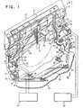
- FIG. 1also represents, in addition to the device of the present invention, the parts of the printer necessary for the explanation of the invention.
- the screen 10maintains the sheet of paper 11 in position relative to the plate 12.
- the assembly shownfurther comprises a conventional printing wheel 13 whose representation is only partial.
- This printing wheel 13includes radial character-carrying tongues 14 rotated in a conventional manner to be placed in the printing position.
- the assemblyalso includes an impact means 15 partially shown and driving the selected tab and the ribbon 16 through the window 17 provided in the screen to ensure the printing operation.
- the print wheel and the screenare driven laterally, in a conventional manner, on the sheet of paper and are mounted on a carriage not shown and controlled by a conventional printer exhaust mechanism, also not shown.
- the window 17 and the screen 10are in the printing position at a certain point on the sheet 11.
- the screencomprises integral ribbon guides comprising uprights 18 which define the lowest trajectory of the ribbon during of its displacement as well as two pairs of curved rods 19-19 'and 20-20' emerging vertically upwards from the uprights 18 to retain the ribbon on its path.
- the rods 19 and 20are closer to the print wheel than the rods 19 'and 20' so that the ribbon makes a slight angle with the screen 10 when it arrives at the gudies and leaves them.
- the two pairs of rodsare part of the end of ribbon detection device.
- the rodsare electrically conductive and respectively connected via corresponding pairs of lines 22-22 'and 23-23' to respective end-of-tape detection circuits 24 and 25.
- These circuits 24 and 25.may be circuits any classics detecting the looping of a circuit and. delivering an appropriate signal.
- the end of the ribbonis detected by a ribbon end tab 21 of electrically conductive material, which is shown in the operating position relative to the rods 20 and 20 '. Since these rods are separate from each other, the electrical circuit is normally open during printer operation. At the end of the ribbon, when the conductive tab capsizes the rods 20 and 20 ′ as shown in FIG. 1, the circuit is closed and the end of ribbon detection circuit delivers the appropriate signal.
- the two sets of rods 19-19 'and 20-20' and their associated end-of-ribbon detection circuits 24 and 25will respectively detect one or the other of the conductive end-of-ribbon tabs mounted at the two ends of the ribbon, according to the direction of movement thereof.
- the screen 10can be readjusted relative to the plate 12 and to the sheet 11. It can be seen that the screen is fixed to a plate 26 by means of two screws 27 and 28 passing through buttonholes 29 and 30 to be screwed into the plate 26. Given that the buttonholes 29 and 30 are oriented vertically, the screen can be moved from bottom to top and vice versa over the length of these buttonholes in order to adjust the position of the screen before tightening the screws 27 and 28 and fixing it to the plate 26.
- the plate 26extends over the entire length of the screen and has at each of its ends an arm 31 pivotally mounted on an axis 32 carried by a support 33 integral with the base 34.
- the baseis fixed to the carriage frame 35 by four screws 36 passing through oversized holes 37 formed in the 'base 34. Since these holes are oversized, the base 34 and thus the screen carried by said base, can be translated in all directions, in the plane of the chassis 35, as shown by the arrows associated with the screws 36 in Figures 1 and 2. To adjust the distance between the screen and the stage and move the screen to the right and left. Since the ribbon guides and the end of ribbon detection means constituted by the pairs of rods 19-19 'and 20-20' are secured to the screen, they will move with it and no particular adjustment of these items will only be required.
- the device of the present inventionallows the screen 10 to be adjusted in rotation relative to the sheet 11 and to the plate 12.
- springs 38exert restoring forces on the arms 31 of the plate 26 in order to pivot the screen around the axes 32 and to recall it towards the sheet 12 and the plate 11.
- Adjusting stop screws 39screwed into these lugs 40 integral with the arms 31, and resting on lugs corresponding 41 secured to the supports 33, can be screwed or unscrewed to drive the screen 10 in rotation about the axes 32 and thus adjust the distance separating it from the sheet 11 and the plate 12.
- the screen 10For cleaning, the screen 10, with its detection means and its ribbon guides can be pivoted on the axes 32 and away from the sheet 11 and the plate 12, by applying and maintaining sufficient manual force to overcome the return forces exerted by the springs 38.
- the screen 10When the cleaning is complete, the screen 10 is returned to its operating position relative to the sheet 11 and the plate 12.
- the position of the ribbon guides and of the detection means end of ribbon which are integral with the screenremains unchanged with respect to the screen during the movement of the latter.
Landscapes
- Impression-Transfer Materials And Handling Thereof (AREA)
- Handling Of Sheets (AREA)
- Handling Of Cut Paper (AREA)
Description
Translated fromFrenchLa présente invention concerne les imprimantes à impact à platine cylindrique et, plus particulièrement, un dispositif à écran guide-papier pour ces imprimantes.The present invention relates to cylindrical platen impact printers and, more particularly, to a paper guide screen device for these printers.
D'une manière classique, les imprimantes à impact à platine cylindrique sont équipées d'un écran guide-papier pour maintenir la feuille d'impression plaquée contre la platine. En général, ces écrans présentent une surface intérieure dont la courbure correspond essentiellement à la courbure de la platine, et sont montés adjacents à la platine mais à une certaine distance de celle-ci de façon qu'une feuille d'impression puisse être introduite entre l'écran et la platine. L'écran présente naturellement une fenêtre au travers de laquelle peut passer une élément porte-caractères pour assurer l'impression de la feuille. D'une manière classique, cette impression par impact est assurée par le déplacement du ruban d'impression sur une trajectoire passant entre l'écran et l'élément porte-caractères qui peut être par exemple un disque ou roue d'impression présentant - des languettes radiales portant les caractères d'impression à leurs extrémités. Lorsqu'un caractère sélectionné est à imprimer, la roue est amenée en rotation dans la position d'impression du caractère sélectionné, puis un moyen d'impact tel qu'un marteau ou autre élément similaire, applique la languette radiale sélectionnée contre le ruban pour entraîner celui-ci au travers de la fenêtre ménagée dans l'écran et frapper le caractère sélectionné contre la feuille de papier ou autre milieu d'impression similaire.Conventionally, impact printers with a cylindrical platen are equipped with a paper guide screen to keep the printing sheet pressed against the platen. In general, these screens have an internal surface whose curvature corresponds essentially to the curvature of the plate, and are mounted adjacent to the plate but at a certain distance from it so that a printing sheet can be introduced between screen and deck. The screen naturally presents a window through which a character-carrying element can pass to ensure the printing of the sheet. In a conventional manner, this impact printing is provided by the displacement of the printing ribbon on a path passing between the screen and the character-carrying element which can be for example a disc or printing wheel having - Radial tabs with the print characters at their ends. When a selected character is to be printed, the wheel is rotated in the printing position of the selected character, then an impact means such as a hammer or the like, applies the selected radial tongue against the ribbon to drag it through the window in the screen and strike the selected character against the sheet of paper or other similar printing medium.
Afin de répondre aux voeux des utilisateurs d'imprimantes demandant des vitesses d'impression dépassant 50 caractères par seconde et approchant les 100 caractères par seconde, l'homme de l'art a essayé de réduire la course d'impression des languettes porte-caractères de la roue d'impression, c'est-à-dire la distance parcourue par les languettes pour appliquer le ruban d'impression contre la feuille. A cet égard, des courses de l'ordre de 2,5mm, c'est-à-dire la distance entre les caractères à imprimer portés par la languette de la roue d'impression et la platine, ne sont pas inimaginables pour des imprimantes à grande vitesse. Etant donné que le ruban, l'écran et le papier doivent pouvoir être contenus et se déplacer en translation dans le faible espace, il en résulte que les tolérances dimensionnelles de ces éléments sont très serrées. La problème posé par le respect de ces tolérances serrées implique le maintien d'une relation spatiale donnée entre la feuille, l'écran et le ruban, non seulement lors de l'assemblage initial de l'imprimante, mais également lorsqu'il est nécessaire de déplacer l'écran pour effectuer des opérations de nettoyage et d'entretien de la machine en utilisation. Lorsque l'écran est périodiquement ajusté, il doit être monté dans une position telle que la distance le séparant de la platine puisse permettre le passage de la feuille d'impression. D'une manière similaire, les guides de ruban, distincts de l'écran et placés de part et d'autre de la fenêtre de l'écran doivent être réglés par rapport à l'écran dans une position spatiale appropriée de façon que la friction créée entre le ruban et l'écran soit réduite au minimum. De plus, les réglages en translation de l'écran sur les axes X et Y (c'est-à-dire respectivement parallèlement et orthogonalement à l'axe de la platine) peuvent requérir des réglages fins de la trajectoire suivie par le ruban sur ces axes X et Y ainsi que des réglages correspondants d'un moyen de détection de fin de ruban particulier associé au ruban.In order to respond to the wishes of users of printers requesting printing speeds exceeding 50 characters per second and approaching 100 characters per second, those skilled in the art tried to reduce the printing stroke of the character tabs of the print wheel, i.e. the distance traveled by the tabs to apply the print ribbon against the sheet. In this respect, strokes of the order of 2.5 mm, that is to say the distance between the characters to be printed carried by the tongue of the print wheel and the plate, are not unimaginable for printers high speed. Since the ribbon, the screen and the paper must be able to be contained and to move in translation in the small space, it follows that the dimensional tolerances of these elements are very tight. The problem of respecting these tight tolerances involves maintaining a given spatial relationship between the sheet, the screen and the ribbon, not only during the initial assembly of the printer, but also when it is necessary. move the screen to perform cleaning and maintenance operations on the machine in use. When the screen is periodically adjusted, it must be mounted in a position such that the distance separating it from the platen can allow the passage of the printing sheet. Similarly, the ribbon guides, separate from the screen and placed on either side of the screen window, should be adjusted relative to the screen in an appropriate spatial position so that the friction created between the ribbon and the screen is minimized. In addition, the adjustments in translation of the screen on the X and Y axes (that is to say respectively parallel and orthogonally to the axis of the stage) may require fine adjustments to the trajectory followed by the ribbon on these X and Y axes as well as corresponding settings of a particular end of ribbon detection means associated with the ribbon.
Même dans le meilleur des cas, les opérations de réglage effectuées dans les imprimantes classiques et concernant l'écran, le guide-ruban et le moyen de détection de fin de ruban, sont toujours longues et fastidieuses et requièrent un personnel très qualifié, du fait de l'indépendance de ces éléments qui implique un réglage particulier de chacun d'eux.Even in the best of cases, the adjustment operations carried out in conventional printers and concerning the screen, the ribbon guide and the end of ribbon detection means, are always long and tedious and require very qualified personnel, because of the independence of these elements which implies a particular adjustment of each of them.
Le dispositif selon la présente invention permet de résoudre les problèmes de tolérances décrits ci-dessus et concernant les rubans et les écrans.The device according to the present invention makes it possible to solve the tolerance problems described above and relating to the ribbons and the screens.
A cet égard, l'objet principal de la présente invention est de fournir des moyens permettant de régler rapidement et simultanément la position du ruban et la position de l'écran, les deux par rapport à la platine.In this regard, the main object of the present invention is to provide means making it possible to quickly and simultaneously adjust the position of the ribbon and the position of the screen, both relative to the plate.
Un objet secondaire de la présente invention est de fournir des moyens permettant de régler la position du moyen de détection de fin de ruban simultanément à celle de l'écran.A secondary object of the present invention is to provide means making it possible to adjust the position of the end of ribbon detection means simultaneously with that of the screen.
Un autre secondaire de la présente invention est de fournir des moyens permettant de sortir temporairement l'écran de sa position de fonctionnement pour le nettoyer et de le remettre en place sans avoir à réajuster les positions du guide-ruban et du moyen de détection de fin de ruban.Another secondary of the present invention is to provide means making it possible to temporarily remove the screen from its operating position to clean it and to replace it without having to readjust the positions of the tape guide and of the end detection means. of ribbon.
Selon la présente invention, l'écran de l'imprimante comportant des moyens de guidage de ruban lesdits moyens de guidage étant destinés à guider le ruban le long d'une trajectoire passant au voisinage de la surface de l'écran opposée à la surface qui est en contact avec la feuille d'impression et les guides de ruban de l'écran assurant le passage du ruban sur la fenêtre ménagée dans l'écran pour permettre l'entraînement du ruban contre la feuille pendant une opération d'impression par impact est caractérisé en ce que les moyens de guidage du ruban d'impression sont incorporés au die écran et sont fixes par rapport à lui.According to the present invention, the screen of the printer comprising ribbon guiding means, said guiding means being intended to guide the ribbon along a path passing in the vicinity of the surface of the screen opposite the surface which is in contact with the printing sheet and the screen ribbon guides ensuring the passage of the ribbon over the window provided in the screen to allow the ribbon to drive against the sheet during an impact printing operation is characterized in that the means for guiding the printing ribbon are incorporated in the screen die and are fixed with respect to it.
Avec une telle structure d'écran, lorsqu'il est nécessaire de placer l'écran dans sa position de fonctionnement par rapport à la platine ou à la roue d'impression ou de l'en entirer, ou lorsque l'écran est réglé en translation sur les axes X et Y, les guides de ruban qui sont solidaires de l'écran, sont déplacés et réglés d'une manière correspondante. Ainsi, les guides de ruban restent toujours dans une position fixe par rapport à l'écran indépendamment du mouvement ou du réglage de celui-ci.With such a screen structure, when it is necessary to place the screen in its operating position relative to the platen or the print wheel or to draw it out, or when the screen is adjusted in translation on the X and Y axes, the ribbon guides which are integral with the screen, are moved and adjusted in a corresponding manner. Thus, the ribbon guides always remain in a fixed position relative to the screen regardless of the movement or the adjustment thereof.
Selon un aspect plus particulier de la présente invention, l'écran comporte en outre des moyens de détection de fin de ruban montés dans une position fixe sur la trajectoire du ruban. Ainsi, d'une manière similaire, lorsque l'écran est déplacé ou réglé sur les axes indiqués ci-dessus, les moyens de détection de fin de ruban sont réglés d'une manière correspondante. Aucun réglage indépendant des guides de ruban ou des moyens de détection de fin de ruban n'est nécessaire avec le dispositif de la présente invention.According to a more particular aspect of the present invention, the screen further comprises means for detecting the end of the tape mounted in a fixed position on the path of the tape. Thus, in a similar manner, when the screen is moved or adjusted on the axes indicated above, the end of ribbon detection means are adjusted in a corresponding manner. No independent adjustment of the ribbon guides or of the end of ribbon detection means is necessary with the device of the present invention.
Selon un autre aspect de la présente invention, afin de permettre un accès facile au côté incurvé de l'écran en contact avec la feuille d'impression, pour sont nettoyage, l'écran est monté de façon à pouvoir pivoter pour s'écarter de la platine, puis pivoter à nouveau dans l'autre sens pour être ramené en position de fonctionnement. Etant donné que les guides de ruban et les moyens de détection de fin de ruban sont solidaires de l'écran, ils pivotent avec celui-ci et aucun réglage indépendant de ces unités n'est nécessaire, ce qui permet un nettoyage encore plus rapide de l'écran.According to another aspect of the present invention, in order to allow easy access to the curved side of the screen in contact with the printing sheet, for cleaning purposes, the screen is mounted so as to be able to pivot to move away from the plate, then pivot again in the other direction to be returned to the operating position. Since the ribbon guides and the end of ribbon detection means are integral with the screen, they pivot with the screen and no independent adjustment of these units is necessary, which allows even faster cleaning of the screen. the screen.
- La figure 1 est une vue partielle en perspective de l'écran avec ses guides de ruban et son dispositif de détection de fin de ruban, selon la présente invention.Figure 1 is a partial perspective view of the screen with its ribbon guides and its end of ribbon detection device, according to the present invention.
- La figure 2 est une vue en coupe du dispositif selon l'invention, prise selon la ligne 2-2 de la figure 1.FIG. 2 is a sectional view of the device according to the invention, taken along line 2-2 of FIG. 1.
On se référera à la figure 1 qui représente également, en plus du dispositif de la présente invention, les parties de l'imprimante nécessaires à l'explication de l'invention.Reference will be made to FIG. 1 which also represents, in addition to the device of the present invention, the parts of the printer necessary for the explanation of the invention.
L'écran 10 maintient la feuille de papier 11 en position par rapport à la platine 12. L'ensemble représenté comprend en outre une roue d'impression classique 13 dont la représentation n'est que partielle. Cette roue d'impression 13 comporte des languettes porte-caractères radiales 14 entraînées en rotation d'une manière classique pour être placées en position d'impression. De plus, l'ensemble comprend également un moyen d'impact 15 représenté partiellement et entraînant la languette sélectionnée et le ruban 16 au travers de la fenêtre 17 ménagée dans l'écran pour assurer l'opération d'impression. La roue d'impression et l'écran sont entraînés latéralement, d'une manière classique, sur la feuille de papier et sont montés sur un chariot non représenté et commandé par un mécanisme d'échappement classique d'imprimante, également non représenté. Pendant une opération d'impression, la fenêtre 17 et l'écran 10 se trouvent en position d'impression en un certain point de la feuille 11.The
Pour la description détaillée de l'écran de la présente invention, on se reportera à la figure 2 en combinaison avec la figure 1. L'écran comporte des guides de ruban solidaires comprenant des montants 18 qui définissent la trajectoire la plus basse du ruban lors de son déplacement ainsi que deux paires de tiges recourbées 19-19' et 20-20' sortant verticalement vers le haut des montants 18 pour retenir le ruban sur sa trajectoire. Bien que cela n'apparaisse pas sur les dessins, les tiges 19 et 20 sont plus rapprochées de la roue d'impression que les tiges 19' et 20' de façon que le ruban fasse un léger angle avec l'écran 10 lorsqu'il arrive sur les gudies et les quitte. D'autre part, les deux paires de tiges font partie du dispositif de détection de fin de ruban. Les tiges sont électriquement conductrices et respectivement connectées par l'intermédiaire de paires correspondantes de lignes 22-22' et 23-23' à des circuits de détection de fin de ruban respectifs 24 et 25. Ces circuits 24 et 25. peuvent être des circuits classiques quelconques détectant le bouclage d'un circuit et . délivrant un signal approprié. L'extrémité du ruban est détectee par une languette de fin de ruban 21 en matière électriquement conductrice, qui est représentée en position de fonctionnement par rapport aux tiges 20 et 20'. Etant donné que ces tiges sont séparées l'une de l'autre, le circuit électrique est normalement ouvert pendant le fonctionnement de l'imprimante. A la fin du ruban, lorsque la languette conductrice chavauche les tiges 20 et 20' comme représenté sur la figure 1, le circuit est bouclé et le circuit de détection de fin de ruban délivre le signal approprié. Les deux ensembles de tiges 19-19' et 20-20' et leurs circuits de détection de fin de ruban associés 24 et 25 détecteront respectivement l'une ou l'autre des languettes conductrices de fin de ruban montées aux deux extrémités du ruban, selon le sens du mouvement de celui-ci.For the detailed description of the screen of the present invention, reference will be made to FIG. 2 in combination with FIG. 1. The screen comprises integral ribbon
On décrira maintenant comment l'écran 10 peut être réajusté par rapport à la platine 12 et à la feuille 11. On voit que l'écran est fixé à une plaque 26 par l'intermédiaire de deux vis 27 et 28 traversant des boutonnières 29 et 30 pour se visser dans la plaque 26. Etatn donné que les boutonnières 29 et 30 sont orientées verticalement, l'écran peut être déplacé de bas en haut et vice versa sur la longueur de ces boutonnières afin de régler la position de l'écran avant de serrer les vis 27 et 28 et de le fixer à la plaque 26. La plaque 26 s'étend sur toute la longueur de l'écran et présente à chacune de ses extrémités un bras 31 monté pivotant sur un axe 32 porté par un support 33 solidaire de l'embase 34. L'embase est fixée sur le châssis de chariot 35 par quatre vis 36 traversant des trous surdimensionnés 37 ménagés dans l'embase 34. Etant donné que ces trous sont surdimensionnés, l'embase 34 et ainsi l'écran porté par ladite embase, peuvent être translatés dans toutes les directions, dans le plan du châssis 35, comme représenté par les flèches associées aux vis 36 sur les figures 1 et 2. Pour régler la distance séparant l'écran de la platine et déplacer l'écran vers la droite et la gauche. Etant donné que les guides de ruban et les moyens de détection de fin de ruban constitués par les paires de tiges 19-19' et 20-20' sont solidaires de l'écran, il se déplaceront avec celui-ci et aucun réglage particulier de ces éléments ne sera nécessaire.We will now describe how the
De plus, le dispositif de la présente invention permet le réglage en rotation de l'écran 10 par rapport à la feuille 11 et à la platine 12. A cette fin, des ressorts 38 exercent des forces de rappel sur les bras 31 de la plaque 26 afin de faire pivoter l'écran autour des axes 32 et de le rappeler vers la feuille 12 et la platine 11. Des vis-butées de réglage 39, vissées dans ces pattes 40 solidaires des bras 31, et s'appuyant sur des pattes correspondantes 41 solidaires des supports 33, peuvent être vissées ou dévissées pour entraîner l'écran 10 en rotation autour des axes 32 et ainsi régler la distance le séparant de la feuille 11 et de la platine 12. Dans ce cas également, les moyens de détection de fin de ruban ainsi que les guides de ruban qui sont solidaires de l'écran, se déplacent avec lui, ce qui évite d'avoir à en effectuer le réglage.In addition, the device of the present invention allows the
Pour le nettoyage, l'écran 10, avec ses moyens de détection et ses guides de ruban peut être pivoté sur les axes 32 et éloigné de la feuille 11 et de la platine 12, en appliquant et en maintenant une force manuelle suffisante pour surpasser les forces de rappel exercées par les ressorts 38. Lorsque le nettoyage est achévé, l'écran 10 est ramené dans sa position de fonctionnement par rapport à la feuille 11 et à la platine 12. La position des guides de ruban et des moyens de détection de fin de ruban qui sont solidaires de l'écran demeure inchangée par rapport à l'écran pendant le mouvement de celui-ci.For cleaning, the
Bien que l'on ait décrit dans ce quie précède et représenté sur les dessins les caractéristiques essentielles de l'invention appliquées à un mode de réalisation préféré de celle-ci, il est évident que l'homme de l'art peut y apporter toutes modifications de forme ou de détail qu'il juge utiles, sans pour autant sortir du cadre de ladite invention.Although the essential characteristics of the invention applied to a preferred embodiment of the invention have been described in the foregoing and represented in the drawings, it is obvious that a person skilled in the art can provide all of them. modifications of form or detail which he judges useful, without departing from the scope of said invention.
Claims (5)
Applications Claiming Priority (2)
| Application Number | Priority Date | Filing Date | Title |
|---|---|---|---|
| US05/958,276US4212552A (en) | 1978-11-06 | 1978-11-06 | Impact printer cardholder with integral ribbon guide and end of ribbon sensor |
| US958276 | 1978-11-06 |
Publications (3)
| Publication Number | Publication Date |
|---|---|
| EP0013292A2 EP0013292A2 (en) | 1980-07-23 |
| EP0013292A3 EP0013292A3 (en) | 1981-01-07 |
| EP0013292B1true EP0013292B1 (en) | 1984-02-15 |
Family
ID=25500808
Family Applications (1)
| Application Number | Title | Priority Date | Filing Date |
|---|---|---|---|
| EP79103694AExpiredEP0013292B1 (en) | 1978-11-06 | 1979-09-28 | Paperguiding screen with integral ribbon guide for an impact printer |
Country Status (6)
| Country | Link |
|---|---|
| US (1) | US4212552A (en) |
| EP (1) | EP0013292B1 (en) |
| JP (1) | JPS5563289A (en) |
| CA (1) | CA1128451A (en) |
| DE (1) | DE2966670D1 (en) |
| IT (1) | IT1162793B (en) |
Families Citing this family (14)
| Publication number | Priority date | Publication date | Assignee | Title |
|---|---|---|---|---|
| JPS6054186B2 (en)* | 1978-09-18 | 1985-11-29 | 株式会社リコー | printing device |
| CH627687A5 (en)* | 1978-12-20 | 1982-01-29 | Hermes Precisa International | DEVICE FOR SETTING UP AND FIXING A PRINTING DISC. |
| JPS5627942U (en)* | 1979-08-10 | 1981-03-16 | ||
| US4326815A (en)* | 1980-01-21 | 1982-04-27 | Ziyad Incorporated | Paper feeding apparatus and method for printing apparatus |
| US4375339A (en)* | 1980-12-01 | 1983-03-01 | International Business Machines Corporation | Electrically conductive ribbon break detector for printers |
| JPS57148682A (en)* | 1981-03-09 | 1982-09-14 | Canon Inc | Ink ribbon delivery mechanism |
| DE3214633C2 (en)* | 1982-04-20 | 1986-10-30 | Nixdorf Computer Ag, 4790 Paderborn | Device for guiding an exchangeable ribbon in a printer |
| US4685818A (en)* | 1985-09-16 | 1987-08-11 | Printronix, Inc. | Ribbon fault detection system |
| DE3700636C1 (en)* | 1987-01-12 | 1988-05-26 | Olympia Aeg | Ribbon device in typewriters or similar office machines |
| DE3819782A1 (en)* | 1988-06-10 | 1989-12-14 | Triumph Adler Ag | TYPEWRITER, PRINTER OR THE LIKE, AND RIBBON TAPE HERE |
| US5074689A (en)* | 1990-01-12 | 1991-12-24 | Smith Corona Corporation | Ribbon cassette with integral paper guide |
| US5098208A (en)* | 1990-01-12 | 1992-03-24 | Smith Corona Corporation | Ribbon cassette with integral paper guide |
| US6503007B1 (en) | 2001-07-27 | 2003-01-07 | Genicom, Llc | Printer ribbon motion detection system |
| WO2006055444A2 (en)* | 2004-11-16 | 2006-05-26 | Polaroid Corporation | Double sided thermal printing device with an improved image registration |
Family Cites Families (12)
| Publication number | Priority date | Publication date | Assignee | Title |
|---|---|---|---|---|
| US1174555A (en)* | 1915-11-27 | 1916-03-07 | Underwood Typewriter Co | Type-writing machine. |
| US1679845A (en)* | 1924-08-16 | 1928-08-07 | Underwood Elliott Fisher Co | Typewriting machine |
| US2044072A (en)* | 1933-02-27 | 1936-06-16 | Remingten Typewriter Company | Typewriting machine |
| US2331331A (en)* | 1940-12-27 | 1943-10-12 | Allen Wales Adding Machine Cor | Printing mechanism |
| US2345557A (en)* | 1943-02-12 | 1944-04-04 | Harmon P Elliott | Apparatus for forming characters on stencils |
| GB706172A (en)* | 1950-02-25 | 1954-03-24 | Ronald Max Ford | Improvements relating to tape feeding appliances for typewriting machines |
| GB717752A (en)* | 1951-02-14 | 1954-11-03 | Frank R Ford Ltd | Improvements relating to typewriting machines |
| US2821284A (en)* | 1954-03-15 | 1958-01-28 | Lamson Paragon Ltd | Carbon transfer material with alarm means for an imprinting machine |
| US3102699A (en)* | 1960-11-07 | 1963-09-03 | Proctor Dictating Machine Corp | Improved drive for sound recording and reproducing apparatus |
| US3404628A (en)* | 1966-07-11 | 1968-10-08 | Alves Photo Service Inc | Automatic marking device |
| US3747734A (en)* | 1971-12-17 | 1973-07-24 | J Hagood | Error correction device |
| DE2608301C2 (en)* | 1976-02-28 | 1986-02-20 | Ncr Corp., Dayton, Ohio | Device for regulating the distance between a print head and a recording medium |
- 1978
- 1978-11-06USUS05/958,276patent/US4212552A/ennot_activeExpired - Lifetime
- 1979
- 1979-08-17JPJP10416279Apatent/JPS5563289A/enactiveGranted
- 1979-09-20CACA336,007Apatent/CA1128451A/ennot_activeExpired
- 1979-09-28EPEP79103694Apatent/EP0013292B1/ennot_activeExpired
- 1979-09-28DEDE7979103694Tpatent/DE2966670D1/ennot_activeExpired
- 1979-10-31ITIT26954/79Apatent/IT1162793B/enactive
Also Published As
| Publication number | Publication date |
|---|---|
| JPS5563289A (en) | 1980-05-13 |
| JPS5730393B2 (en) | 1982-06-28 |
| DE2966670D1 (en) | 1984-03-22 |
| EP0013292A2 (en) | 1980-07-23 |
| EP0013292A3 (en) | 1981-01-07 |
| CA1128451A (en) | 1982-07-27 |
| IT7926954A0 (en) | 1979-10-31 |
| US4212552A (en) | 1980-07-15 |
| IT1162793B (en) | 1987-04-01 |
Similar Documents
| Publication | Publication Date | Title |
|---|---|---|
| EP0013292B1 (en) | Paperguiding screen with integral ribbon guide for an impact printer | |
| FR2565010A1 (en) | TOUCH READING DEVICE | |
| FR2829964A1 (en) | OPENABLE AND LOCKABLE THERMAL PRINTING DEVICE | |
| EP0148074B1 (en) | Device for turning paper webs in a perfecting printing machine | |
| CH669582A5 (en) | ||
| CH632192A5 (en) | DEVICE FOR THE DRY TRANSFER OF INK SIGNS. | |
| FR2496157A1 (en) | X-ARM TYPE WINDOW REGULATOR FOR MOTOR VEHICLE | |
| EP0087837B1 (en) | Apparatus for printing information on a record carrier | |
| EP1145196B1 (en) | Ticket dispensing apparatus | |
| FR2820234A1 (en) | DEVICE FOR PRESENTING SAMPLES IN PARTICULAR FOR COSMETIC PRODUCTS | |
| EP0960414A1 (en) | Poster panel with endless display strip | |
| FR2508259A1 (en) | Thermal printer using coloured printing film - has spring buffers allowing film to stop momentarily during printing operation and subsequently moving film during retreat of head | |
| EP0030204B1 (en) | Device for classifying various information | |
| FR2460213A1 (en) | Folding machine for letters and documents - has location stops on tray and press down fold marker to provide three or four thicknesses | |
| EP0027546B1 (en) | Individual-sheet feeding device | |
| EP0640485B1 (en) | Thermal printer | |
| FR2654677A1 (en) | Adjustable set square | |
| FR2729336A1 (en) | Machine for cutting, pre-cutting or perforating sheet of paper | |
| FR2766411A1 (en) | Thermal transfer paper printer | |
| LU83200A1 (en) | APPARATUS FOR DISPENSING PRODUCTS IN ROLLS, IN PARTICULAR PAPER TOWELS | |
| WO1999002347A1 (en) | Thermal transfer printing | |
| CH624630A5 (en) | Portable machine for printing labels | |
| FR2699904A1 (en) | Distributor of roll wiping products. | |
| FR2570564A1 (en) | Printer ribbon supply arrangement for facsimile machine | |
| FR2464829A1 (en) | Pantograph machine for signing official documents - has pens governed by contoured cam with positional adjustment to obviate adjustment of paper |
Legal Events
| Date | Code | Title | Description |
|---|---|---|---|
| PUAI | Public reference made under article 153(3) epc to a published international application that has entered the european phase | Free format text:ORIGINAL CODE: 0009012 | |
| AK | Designated contracting states | Designated state(s):DE FR GB | |
| PUAL | Search report despatched | Free format text:ORIGINAL CODE: 0009013 | |
| 17P | Request for examination filed | Effective date:19810205 | |
| GRAA | (expected) grant | Free format text:ORIGINAL CODE: 0009210 | |
| AK | Designated contracting states | Designated state(s):DE FR GB | |
| REF | Corresponds to: | Ref document number:2966670 Country of ref document:DE Date of ref document:19840322 | |
| PGFP | Annual fee paid to national office [announced via postgrant information from national office to epo] | Ref country code:FR Payment date:19840829 Year of fee payment:6 | |
| PLBE | No opposition filed within time limit | Free format text:ORIGINAL CODE: 0009261 | |
| STAA | Information on the status of an ep patent application or granted ep patent | Free format text:STATUS: NO OPPOSITION FILED WITHIN TIME LIMIT | |
| 26N | No opposition filed | ||
| GBPC | Gb: european patent ceased through non-payment of renewal fee | ||
| PG25 | Lapsed in a contracting state [announced via postgrant information from national office to epo] | Ref country code:GB Effective date:19881118 | |
| PGFP | Annual fee paid to national office [announced via postgrant information from national office to epo] | Ref country code:DE Payment date:19891012 Year of fee payment:11 | |
| PG25 | Lapsed in a contracting state [announced via postgrant information from national office to epo] | Ref country code:FR Effective date:19900531 | |
| REG | Reference to a national code | Ref country code:FR Ref legal event code:ST | |
| PG25 | Lapsed in a contracting state [announced via postgrant information from national office to epo] | Ref country code:DE Effective date:19910601 |