EP0013132B1 - Apparatus comprising a dosaging device for a liquid product and a method for it - Google Patents
Apparatus comprising a dosaging device for a liquid product and a method for itDownload PDFInfo
- Publication number
- EP0013132B1 EP0013132B1EP79302970AEP79302970AEP0013132B1EP 0013132 B1EP0013132 B1EP 0013132B1EP 79302970 AEP79302970 AEP 79302970AEP 79302970 AEP79302970 AEP 79302970AEP 0013132 B1EP0013132 B1EP 0013132B1
- Authority
- EP
- European Patent Office
- Prior art keywords
- chamber
- cartons
- product
- containers
- aseptic
- Prior art date
- Legal status (The legal status is an assumption and is not a legal conclusion. Google has not performed a legal analysis and makes no representation as to the accuracy of the status listed.)
- Expired
Links
- 239000012263liquid productSubstances0.000titleclaimsdescription9
- 238000000034methodMethods0.000titleclaims2
- 239000000047productSubstances0.000claimsdescription14
- 239000007788liquidSubstances0.000claimsdescription13
- MHAJPDPJQMAIIY-UHFFFAOYSA-NHydrogen peroxideChemical compoundOOMHAJPDPJQMAIIY-UHFFFAOYSA-N0.000claimsdescription12
- 239000012530fluidSubstances0.000claimsdescription6
- 230000001954sterilising effectEffects0.000claimsdescription6
- 238000007789sealingMethods0.000claimsdescription5
- 238000005086pumpingMethods0.000claimsdescription4
- 230000005855radiationEffects0.000claimsdescription3
- 238000005507sprayingMethods0.000claims3
- 230000000844anti-bacterial effectEffects0.000claims2
- 239000003570airSubstances0.000description24
- 235000013336milkNutrition0.000description11
- 239000008267milkSubstances0.000description11
- 210000004080milkAnatomy0.000description11
- 235000020191long-life milkNutrition0.000description6
- 238000004140cleaningMethods0.000description4
- 238000009455aseptic packagingMethods0.000description3
- 239000000945fillerSubstances0.000description3
- 239000007921spraySubstances0.000description3
- 210000003414extremityAnatomy0.000description2
- 238000005187foamingMethods0.000description2
- 230000002070germicidal effectEffects0.000description2
- 210000001364upper extremityAnatomy0.000description2
- 239000012080ambient airSubstances0.000description1
- 230000002301combined effectEffects0.000description1
- 230000001419dependent effectEffects0.000description1
- 239000003599detergentSubstances0.000description1
- 230000000694effectsEffects0.000description1
- 239000006260foamSubstances0.000description1
- 239000007789gasSubstances0.000description1
- 238000010438heat treatmentMethods0.000description1
- 210000003141lower extremityAnatomy0.000description1
- 238000004519manufacturing processMethods0.000description1
- 230000003534oscillatory effectEffects0.000description1
- 238000004806packaging method and processMethods0.000description1
- -1polytetrafluoroethylenePolymers0.000description1
- 229920001343polytetrafluoroethylenePolymers0.000description1
- 239000004810polytetrafluoroethyleneSubstances0.000description1
- 230000001105regulatory effectEffects0.000description1
- 230000000717retained effectEffects0.000description1
- 230000002000scavenging effectEffects0.000description1
- 229910001220stainless steelInorganic materials0.000description1
- 239000010935stainless steelSubstances0.000description1
- 238000004659sterilization and disinfectionMethods0.000description1
- 239000000126substanceSubstances0.000description1
- 230000002195synergetic effectEffects0.000description1
- 229920001169thermoplasticPolymers0.000description1
- 239000004416thermosoftening plasticSubstances0.000description1
Images


Classifications
- B—PERFORMING OPERATIONS; TRANSPORTING
- B65—CONVEYING; PACKING; STORING; HANDLING THIN OR FILAMENTARY MATERIAL
- B65B—MACHINES, APPARATUS OR DEVICES FOR, OR METHODS OF, PACKAGING ARTICLES OR MATERIALS; UNPACKING
- B65B55/00—Preserving, protecting or purifying packages or package contents in association with packaging
- B65B55/02—Sterilising, e.g. of complete packages
- B65B55/027—Packaging in aseptic chambers
- B—PERFORMING OPERATIONS; TRANSPORTING
- B65—CONVEYING; PACKING; STORING; HANDLING THIN OR FILAMENTARY MATERIAL
- B65B—MACHINES, APPARATUS OR DEVICES FOR, OR METHODS OF, PACKAGING ARTICLES OR MATERIALS; UNPACKING
- B65B3/00—Packaging plastic material, semiliquids, liquids or mixed solids and liquids, in individual containers or receptacles, e.g. bags, sacks, boxes, cartons, cans, or jars
- B65B3/04—Methods of, or means for, filling the material into the containers or receptacles
- B65B3/10—Methods of, or means for, filling the material into the containers or receptacles by application of pressure to material
- B65B3/12—Methods of, or means for, filling the material into the containers or receptacles by application of pressure to material mechanically, e.g. by pistons or pumps
Definitions
- This inventionrelates to apparatus comprising a dosaging device arranged to deliver a liquid product in predetermined individual doses, particularly in the aseptic packaging of liquid products, for example long-life milk, in cartons.
- Filling stations of machines for automatically opening-out, filling, closing and sealing cartonsare of various forms, for example those disclosed in United States Patents 2,841,936 and 3,352,458.
- United States Patent 2841936discloses such a machine in which the filling mechanism comprises a tank having a discharge nozzle and a normally closed valve which controls the flow of liquid through the nozzle, which valve is operated to its open position by a solenoid and is retained in its open position as long as the solenoid remains energized.
- a float controlled mechanismis provided in the tank to control the admittance of fluid thereinto and is arranged to maintain a substantially constant level in the tank so as thereby to provide a controlled rate of discharge through the nozzle.
- United States Patent 3,352,458discloses another such machine, whereof the filler unit has a circular delivery tank provided with an inlet and a pair of outlets spaced from each other lengthwise of the carton track so that each will overlie the open mouth of a carton in both of its positions in which it is stopped under the filler unit.
- Each outlethas an internal seat for an outlet valve and a depending nozzle provided with a cap connected thereto as by a bayonet type of joint and having outlet ports disposed to provide for a desired flow therethrough in a manner minimizing foaming.
- the capsmay be removed and replaced by others providing for a different volumetric flow or one may be replaced by a shutoff cap to block all flow through the outlet to the nozzle to which it is attached.
- Each valveis adapted to be closed and held closed by an electro-magnet against the action of a float, with each float having vertically aligned upper and lower rods connected thereto.
- Each lower rodis connected to its valve and each upper rod includes a part functioning as the core of a valve-operating electro-magnet.
- a surge tankhas an inlet which is horizontal as an aid against foaming, from a source such as a pasteurizer or homogenizer, for example, and controlled by a float valve, and an outlet connected to the inlet of the delivery tank by a valve.
- the electro-magnets in control of the outlet valvesare de-energized for the interval determined by a timing relay. If there is then a sufficient body of liquid in the delivery tank the outlet valves open and stay open until the electro-magnets are again energized or until the liquid level in the tank drops sufficiently.
- the known filling stationshave the disadvantage that during use they contain, in contact with the liquid, voids or air spaces, which allow microbes to obtain access to the liquid.
- British Patent Specification No. 1335007discloses a metering device for filling packaging containers with liquids and pastes, comprising at least one unit having an inlet valve connected to a feed line and an outlet valve which is connected by a bellows of polytetrafluoroethylene, for example, to the inlet valve and which has a valve body in the form of a diaphragm carrying an outlet nozzle, the two ends of the bellows of the or each unit being clamped to two spaced horizontal plates which are relatively movable through an adjustable distance, there being some means to open the inlet valve when the plates are moving apart and to close the inlet valve when the plates are moving together, the outlet valve being arranged to open when the plates are moving together and to close when the plates are moving apart.
- the inlet valvecan consist of a stem extending through the wall of ducting leading to the bellows and provided at its end within the ducting with a frusto-conical valve plate which co-operates with a similarly shaped valve seat formed by an internal shoulder of the ducting.
- the diaphragm of the outlet valvecan be arranged to be held in a closed position by compressed air introduced around the nozzle and beneath the diaphragm.
- the diaphragm of the outlet valvemay instead be prestressed so that it is bent upwardly and not downwardly when it is relaxed. In this instance, it is possible to dispense with the compressed air control, since the outlet valve is always in the closed position except when the lower plate is being moved upwardly.
- the inlet valvewhich is angled, may be replaced by a vertical axis valve which, if required, may also be provided with a pneumatic control arrangement.
- apparatuscomprising a dosaging device arranged to deliver a liquid product in predetermined individual doses, a pumping device arranged to deliver continuously said product under pressure, and a chamber by way of which said pumping device communicates with said dosaging device and whereof the volume of said product therein varies in dependence on the difference between the rates of flow of said product there-into and therefrom, characterised in that said chamber has a flexible wall part whereby the volume of said chamber varies with said volume of said product.
- the machine 1 for carrying out aseptic packagingincludes at one end of the machine a conventional device 2 for pre-forming (including bottom sealing) gable- topped cartons.
- the open-topped, pre-formed cartonsare taken to the other end of the machine through a closed channel 3 by means of a chain system.
- the channel 3is bounded by covers 4 individually liftable about hinges to give access to the channel interior.
- the open-topped cartonsare advanced stepwise and in a vertically upright condition by means of conveying chains 5 along a hairpin-shaped path P of which an advance leg extends along the machine towards the device 2 and a return leg extends along the machine 1 back towards its front end.
- the cartonsexit from the channel 3 directly into an aseptic chamber 6 which totally encloses the chains 5 and which is provided with access covers 6"'.
- the chains 5,which are arranged coextensively one above another, have projecting therefrom outwardly of the path P long lugs 5' which extend beyond guide strips extending along the path P, the cartons being received among and advanced along the path P by the long lugs 5' and being supported at one side by the chains 5 and at the other side by the guide strips.
- the chains 5carry the cartons first of all to a top pre-breaking device 7, where the open top of each carton is pre-broken.
- the cartonsare passed beneath high-intensity ultraviolet germicidal lamps 8 which extend over a section of the hairpin-shaped path P which forms at least a major portion, in the present case in fact a major portion, of the length of the advance leg of the path P.
- some means for introducing into the interior of the carton a fine spray of hydrogen peroxideH 2 0 2 .
- This meanscomprises a nozzle arrangement 7' incorporated in the pre-breaker 7 and serving to spray particularly the inside of the carton with H 2 0 2 .
- the combined effect on the interiors of the cartons of the ultraviolet radiation and the hydrogen peroxidehas a synergistic sterilizing action which is highly germicidal.
- the chains 5carry the cartons round through 180° to start the return leg of the path P.
- the cartonsfirst arrive at a filling device 9 where the cartons are filled with an aseptic product, for example long-life milk, the cartons then proceeding to a top heating device 10 where thermoplastics surfaces of the top of each carton are heated to a tacky condition, and the cartons are then advanced to a top sealing device 11 where the gable tops are sealed.
- the carbonsleave the aseptic chamber 6 at an exit hole 6" therefrom at the front end of the machine.
- aseptic airis fed from a main sterile air filter to aseptic air inlets 13 and 13' of the chamber 6, in which chamber the aseptic air flows from the inlet 13 relatively smoothly to the front end of the chamber 6, where the aseptic air leaves via an aseptic air outlet 14.
- the aseptic airact as a scavenging gas removing microbes and hydrogen peroxide from the chamber 6, particularly tending to prevent the microbes and the hydrogen peroxide from being carried up to the filling device 9, but the aseptic air also maintains the interior of the chamber 6 at a pressure slightly above atmospheric and thus discourages the entry of ambient air into the chamber.
- the top pre-breaker 7is in two sections 71 and 72 which are carried by a common horizontal support 73 itself carried by two horizontal arms 74 fixed to a vertically reciprocating plunger 75.
- the section 71comprises two substantially triangular flaps 76 turnable about respective substantially horizontal parallel pivots 77 by respective oscillatory cranks 78.
- the pre-breaking device 7is lowered onto the two cartons beneath it, and performs its pre-breaking and simultaneously the H 2 0 2 is sprayed into the carton immediately beyond the section 72 by the nozzle device 7'.
- the filling device 9is particularly designed to prevent microbes obtaining access to the aseptic liquid product being supplied to the chamber 6.
- the filling deviceincludes a mounting frame 20 which mounts four stainless steel reciprocatory bellows 21 having bottom walls which are reci- procatorily driven by respective reciprocatory plungers 22 and having top flanges fixed to respective lower limbs of T-unions 23.
- Respective upper limbs of the unions 23contain respective spring-loaded, non-return, inlet valves which open to allow downward flow through the limbs.
- Intermediate limbs of the respective unions 23are connected to respective arcuate pipes 24 which curve downwardly and which at their lower ends are connected to respective outlet nozzles 25 which contain respective spring-loaded, non-return, outlet valves.
- the chains 5advance the cartons stepwise directly below the line of nozzles 25 and a selected number of the bellows 21 are operated each to deliver a predetermined dosage of long-life milk to the vertically upright cartons, the number of bellows 21 operated being dependent upon the nominal capacity of the cartons.
- each bellows 21being preset to deliver a halfpint at each reciprocation, all four bellows 21 are operated for cartons which can each hold one quart.
- the inlet valve in its union 23is held closed by its spring and by the milk pressure, the inlet valve is automatically opened against the action of its spring so that the bellows 21 can draw in milk from an expansion device 26 shown in Figures 8 and 9.
- the device 26is connected to the upper limbs of all of the T-unions 23 by way of its outlet 27.
- a pump(not shown) continuously pumps long-life milk into the device 26 through its inlet 28.
- the interior of the device 26is divided into an expansion chamber 29 and a constant-pressure chamber 30 by an annular bellows 31 and a rigid, movable, end closure wall 32 thereof.
- the chamber 30is set at a substantially constant pressure owing to the provision of a pressure- regulated air supply to the chamber 30 via a port 33 in a removable end wall 34 of the device 26. There extends through the wall 34 in a fluid-tight manner a rod 35 which is fixed at one end to the plate 32.
- the rod 35carries abutment flanges 36 which limit the degree of movement of the wall 32 relative to the wall 34.
- the rod 35also carries a pointer 37 which moves over a scale 38 to indicate the position of the wall 32 in the device 26.
- the filling systemis always absolutely full of long-life milk, so that there are no voids or air spaces, which would possibly allow microbes to obtain access to the milk.
- Another advantage of the present filling systemis that all of the internal surface area of the system which is use is in contact with the long-life milk can itself easily be sterilised by simply passing a very hot liquid, chemical cleaning fluid or steam through the filling system, so that all of that internal surface area comes into contact with the very hot liquid, the fluid, or the steam.
- a carton Cis shown being filled from one of the nozzles 25. It will be noted that, in this modified manner of filling, the carton C is in a position inclined to the vertical, so that the milk flowing from the nozzle 25 falls down onto an internal face of the carton C which face is inclined to the vertical and is directly below the nozzle 25.
- the arrangement shown in Figure 10has the advantage of minimising the production of foam on the top of the milk.
- the cartons Cmove along the path P in upright positions, except in the region of the filling device 9, where they are in a tilted condition. It will be appreciated that movement of the carton from its upright condition to its tilted condition and then back to its upright condition can be produced in various ways, particularly by suitable design of the chains 5 and/or the guide strips for the cartons.
- the machine 1also includes automatically controlled means for cleaning the internal surface of the aseptic chamber 6, this means consisting of spray nozzles 41 distributed centrally along the length of the chamber. These nozzles serve to supply a cleaning fluid, e.g. a hot detergent solution or steam, to the interior of the chamber 6 in such a manner that the whole of the interior of the chamber 6 receives the cleaning fluid, which can then be drained off through a drain (not shown).
- a cleaning fluide.g. a hot detergent solution or steam
- the machine 1, particularly the aseptic chamber 6 and the associated machine parts, such as the items 5 to 11,are so designed that the only non-aseptic matter deliberately introduced into the chamber 6 is the preformed cartons C.
- the entry 3' where the empty cartons enter the aseptic chamber 6 and the exit 6" where the filled cartons leave the aseptic chambercan be sealed off outside the chamber 6 by respective air curtains of aseptic air at higher pressure.
- air curtainsare established by slotted tubes 81 and 82 seen in Figures 4 and 3, respectively.
- the aseptic air for the curtainsis taken from a separate sterile air filter giving higher pressure than the main sterile air filter for the chamber 6 itself.
Landscapes
- Engineering & Computer Science (AREA)
- Mechanical Engineering (AREA)
- Basic Packing Technique (AREA)
- Food Preservation Except Freezing, Refrigeration, And Drying (AREA)
- Apparatus For Disinfection Or Sterilisation (AREA)
- Containers And Plastic Fillers For Packaging (AREA)
Description
- This invention relates to apparatus comprising a dosaging device arranged to deliver a liquid product in predetermined individual doses, particularly in the aseptic packaging of liquid products, for example long-life milk, in cartons.
- Filling stations of machines for automatically opening-out, filling, closing and sealing cartons are of various forms, for example those disclosed in United States Patents 2,841,936 and 3,352,458.
- United States Patent 2841936 discloses such a machine in which the filling mechanism comprises a tank having a discharge nozzle and a normally closed valve which controls the flow of liquid through the nozzle, which valve is operated to its open position by a solenoid and is retained in its open position as long as the solenoid remains energized. A float controlled mechanism is provided in the tank to control the admittance of fluid thereinto and is arranged to maintain a substantially constant level in the tank so as thereby to provide a controlled rate of discharge through the nozzle.
- United States Patent 3,352,458 discloses another such machine, whereof the filler unit has a circular delivery tank provided with an inlet and a pair of outlets spaced from each other lengthwise of the carton track so that each will overlie the open mouth of a carton in both of its positions in which it is stopped under the filler unit. Each outlet has an internal seat for an outlet valve and a depending nozzle provided with a cap connected thereto as by a bayonet type of joint and having outlet ports disposed to provide for a desired flow therethrough in a manner minimizing foaming. The caps may be removed and replaced by others providing for a different volumetric flow or one may be replaced by a shutoff cap to block all flow through the outlet to the nozzle to which it is attached.
- Each valve is adapted to be closed and held closed by an electro-magnet against the action of a float, with each float having vertically aligned upper and lower rods connected thereto. Each lower rod is connected to its valve and each upper rod includes a part functioning as the core of a valve-operating electro-magnet.
- A surge tank has an inlet which is horizontal as an aid against foaming, from a source such as a pasteurizer or homogenizer, for example, and controlled by a float valve, and an outlet connected to the inlet of the delivery tank by a valve.
- Whenever a carton is under an outlet of the filler unit, the electro-magnets in control of the outlet valves are de-energized for the interval determined by a timing relay. If there is then a sufficient body of liquid in the delivery tank the outlet valves open and stay open until the electro-magnets are again energized or until the liquid level in the tank drops sufficiently.
- The known filling stations have the disadvantage that during use they contain, in contact with the liquid, voids or air spaces, which allow microbes to obtain access to the liquid.
- British Patent Specification No. 1335007 discloses a metering device for filling packaging containers with liquids and pastes, comprising at least one unit having an inlet valve connected to a feed line and an outlet valve which is connected by a bellows of polytetrafluoroethylene, for example, to the inlet valve and which has a valve body in the form of a diaphragm carrying an outlet nozzle, the two ends of the bellows of the or each unit being clamped to two spaced horizontal plates which are relatively movable through an adjustable distance, there being some means to open the inlet valve when the plates are moving apart and to close the inlet valve when the plates are moving together, the outlet valve being arranged to open when the plates are moving together and to close when the plates are moving apart. The inlet valve can consist of a stem extending through the wall of ducting leading to the bellows and provided at its end within the ducting with a frusto-conical valve plate which co-operates with a similarly shaped valve seat formed by an internal shoulder of the ducting. The diaphragm of the outlet valve can be arranged to be held in a closed position by compressed air introduced around the nozzle and beneath the diaphragm. However, the diaphragm of the outlet valve may instead be prestressed so that it is bent upwardly and not downwardly when it is relaxed. In this instance, it is possible to dispense with the compressed air control, since the outlet valve is always in the closed position except when the lower plate is being moved upwardly. However, in the latter circumstance, i.e. when the bellows is being compressed, the pressure of the liquid in the bellows overcomes the prestress of the diaphragm, so that the outlet valve opens and allows the liquid to escape. However, such an arrangement has the disadvantage of lesser operational reliability than that utilizing compressed air control. The inlet valve, which is angled, may be replaced by a vertical axis valve which, if required, may also be provided with a pneumatic control arrangement.
- According to the present invention, there is provided apparatus comprising a dosaging device arranged to deliver a liquid product in predetermined individual doses, a pumping device arranged to deliver continuously said product under pressure, and a chamber by way of which said pumping device communicates with said dosaging device and whereof the volume of said product therein varies in dependence on the difference between the rates of flow of said product there-into and therefrom, characterised in that said chamber has a flexible wall part whereby the volume of said chamber varies with said volume of said product.
- Owing to the invention, it is possible to avoid the presence in the apparatus of voids or air spaces in contact with the liquid product during use of the apparatus.
- In order that the invention may be clearly understood and readily carried into effect, reference will now be made, by way of example, to the accompanying drawings, in which:-
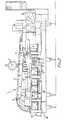
- Figure 1 shows a diagrammatic top plan view of an aseptic packaging machine,
- Figure 2 shows a diagrammatic side elevation of the machine,
- Figure 3 shows a diagrammatic end elevation of the machine in the direction of the arrow III in Figure 2,
- Figure 4 shows a sectional plan view of the left-hand end of the machine in Figure 1,
- Figure 5 shows a sectional end elevation of a top pre-breaking device of the machine,
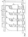
- Figure 6 shows a side elevation of part of a dosaging filling device of the machine,
- Figure 7 shows a partly sectional end elevation of that part of the filling device,
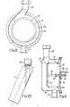
- Figure 8 shows a sectional side elevation of an expansion device of the filling device,
- Figure 9 shows a sectional end elevation of the expansion device, and
- Figure 10 shows diagrammatically a modified manner of filling a carton by means of the filling device.
- Referring to the drawings, the
machine 1 for carrying out aseptic packaging includes at one end of the machine aconventional device 2 for pre-forming (including bottom sealing) gable- topped cartons. The open-topped, pre-formed cartons are taken to the other end of the machine through a closedchannel 3 by means of a chain system. Thechannel 3 is bounded by covers 4 individually liftable about hinges to give access to the channel interior. At this front end of the machine, the open-topped cartons are advanced stepwise and in a vertically upright condition by means of conveyingchains 5 along a hairpin-shaped path P of which an advance leg extends along the machine towards thedevice 2 and a return leg extends along themachine 1 back towards its front end. The cartons exit from thechannel 3 directly into anaseptic chamber 6 which totally encloses thechains 5 and which is provided with access covers 6"'. Thechains 5, which are arranged coextensively one above another, have projecting therefrom outwardly of the path P long lugs 5' which extend beyond guide strips extending along the path P, the cartons being received among and advanced along the path P by the long lugs 5' and being supported at one side by thechains 5 and at the other side by the guide strips. Thechains 5 carry the cartons first of all to a top pre-breaking device 7, where the open top of each carton is pre-broken. Then the cartons are passed beneath high-intensity ultravioletgermicidal lamps 8 which extend over a section of the hairpin-shaped path P which forms at least a major portion, in the present case in fact a major portion, of the length of the advance leg of the path P. In the region of the beginning of this section of the path P, there is arranged some means for introducing into the interior of the carton a fine spray of hydrogen peroxide (H202). This means comprises a nozzle arrangement 7' incorporated in the pre-breaker 7 and serving to spray particularly the inside of the carton withH 202. The combined effect on the interiors of the cartons of the ultraviolet radiation and the hydrogen peroxide has a synergistic sterilizing action which is highly germicidal. Where the degree of sterilisation required is not very great, it is possible to omit use of hydrogen peroxide. At the downstream end of this path section, thechains 5 carry the cartons round through 180° to start the return leg of the path P. On this leg, the cartons first arrive at afilling device 9 where the cartons are filled with an aseptic product, for example long-life milk, the cartons then proceeding to atop heating device 10 where thermoplastics surfaces of the top of each carton are heated to a tacky condition, and the cartons are then advanced to atop sealing device 11 where the gable tops are sealed. The carbons leave theaseptic chamber 6 at anexit hole 6" therefrom at the front end of the machine. Throughout the operation of the machine, aseptic air is fed from a main sterile air filter toaseptic air inlets 13 and 13' of thechamber 6, in which chamber the aseptic air flows from theinlet 13 relatively smoothly to the front end of thechamber 6, where the aseptic air leaves via anaseptic air outlet 14. Not only does the aseptic air act as a scavenging gas removing microbes and hydrogen peroxide from thechamber 6, particularly tending to prevent the microbes and the hydrogen peroxide from being carried up to thefilling device 9, but the aseptic air also maintains the interior of thechamber 6 at a pressure slightly above atmospheric and thus discourages the entry of ambient air into the chamber. - Referring particularly to Figures 4 and 5, the top pre-breaker 7 is in two
sections horizontal support 73 itself carried by twohorizontal arms 74 fixed to a verticallyreciprocating plunger 75. Thesection 71 comprises two substantiallytriangular flaps 76 turnable about respective substantially horizontalparallel pivots 77 by respectiveoscillatory cranks 78. Between each two advances of the stepwise-advanced cartons, the pre-breaking device 7 is lowered onto the two cartons beneath it, and performs its pre-breaking and simultaneously theH 202 is sprayed into the carton immediately beyond thesection 72 by the nozzle device 7'. - The
filling device 9 is particularly designed to prevent microbes obtaining access to the aseptic liquid product being supplied to thechamber 6. Referring to Figures 6 to 9, the filling device includes amounting frame 20 which mounts four stainless steelreciprocatory bellows 21 having bottom walls which are reci- procatorily driven byrespective reciprocatory plungers 22 and having top flanges fixed to respective lower limbs of T-unions 23. Respective upper limbs of theunions 23 contain respective spring-loaded, non-return, inlet valves which open to allow downward flow through the limbs. Intermediate limbs of therespective unions 23 are connected to respectivearcuate pipes 24 which curve downwardly and which at their lower ends are connected torespective outlet nozzles 25 which contain respective spring-loaded, non-return, outlet valves. Thechains 5 advance the cartons stepwise directly below the line ofnozzles 25 and a selected number of thebellows 21 are operated each to deliver a predetermined dosage of long-life milk to the vertically upright cartons, the number ofbellows 21 operated being dependent upon the nominal capacity of the cartons. Thus, with eachbellows 21 being preset to deliver a halfpint at each reciprocation, all fourbellows 21 are operated for cartons which can each hold one quart. On eachbellows 21 performing a pressure stroke, because the inlet valve in itsunion 23 is held closed by its spring and by the milk pressure, the inlet valve is automatically opened against the action of its spring so that thebellows 21 can draw in milk from anexpansion device 26 shown in Figures 8 and 9. Thedevice 26 is connected to the upper limbs of all of the T-unions 23 by way of itsoutlet 27. A pump (not shown) continuously pumps long-life milk into thedevice 26 through itsinlet 28. The interior of thedevice 26 is divided into anexpansion chamber 29 and a constant-pressure chamber 30 by anannular bellows 31 and a rigid, movable,end closure wall 32 thereof. Thechamber 30 is set at a substantially constant pressure owing to the provision of a pressure- regulated air supply to thechamber 30 via aport 33 in aremovable end wall 34 of thedevice 26. There extends through thewall 34 in a fluid-tight manner arod 35 which is fixed at one end to theplate 32. Therod 35 carriesabutment flanges 36 which limit the degree of movement of thewall 32 relative to thewall 34. Therod 35 also carries apointer 37 which moves over ascale 38 to indicate the position of thewall 32 in thedevice 26. In use of the machine, when the instantaneous rate of delivery of the pump to theinlet 28 exceeds the rate of drawing of the milk into thebellows 21 via theoutlet 27, thewall 32 is moved by the pressure of the milk to the right in Figure 9 against the action of the air pressure in thechamber 30, so that theexpansion device 26 acts temporarily as a reservoir until the rate of drawing of the milk into thebellows 21 exceeds the rate of delivery by the pump, in which case theplate 32 moves to the left in Figure 9 under the action of the air pressure in thechamber 30. It will thus be appreciated that, at least between the pump (not shown) and the outlet valves in thenozzles 25, the filling system is always absolutely full of long-life milk, so that there are no voids or air spaces, which would possibly allow microbes to obtain access to the milk. Another advantage of the present filling system is that all of the internal surface area of the system which is use is in contact with the long-life milk can itself easily be sterilised by simply passing a very hot liquid, chemical cleaning fluid or steam through the filling system, so that all of that internal surface area comes into contact with the very hot liquid, the fluid, or the steam. - Referring to Figure 10, a carton C is shown being filled from one of the
nozzles 25. It will be noted that, in this modified manner of filling, the carton C is in a position inclined to the vertical, so that the milk flowing from thenozzle 25 falls down onto an internal face of the carton C which face is inclined to the vertical and is directly below thenozzle 25. Comared to a conventional arrangement in which a nozzle pours milk down into a carton arranged in a substantially exactly upright position directly below the nozzle and thus the milk leaving the nozzle virtually always pours directly onto a body of milk in the carton, the arrangement shown in Figure 10 has the advantage of minimising the production of foam on the top of the milk. In the present case, the cartons C move along the path P in upright positions, except in the region of thefilling device 9, where they are in a tilted condition. It will be appreciated that movement of the carton from its upright condition to its tilted condition and then back to its upright condition can be produced in various ways, particularly by suitable design of thechains 5 and/or the guide strips for the cartons. - The
machine 1 also includes automatically controlled means for cleaning the internal surface of theaseptic chamber 6, this means consisting ofspray nozzles 41 distributed centrally along the length of the chamber. These nozzles serve to supply a cleaning fluid, e.g. a hot detergent solution or steam, to the interior of thechamber 6 in such a manner that the whole of the interior of thechamber 6 receives the cleaning fluid, which can then be drained off through a drain (not shown). - The
machine 1, particularly theaseptic chamber 6 and the associated machine parts, such as theitems 5 to 11, are so designed that the only non-aseptic matter deliberately introduced into thechamber 6 is the preformed cartons C. - The entry 3' where the empty cartons enter the
aseptic chamber 6 and theexit 6" where the filled cartons leave the aseptic chamber can be sealed off outside thechamber 6 by respective air curtains of aseptic air at higher pressure. Thus the lower-pressure aseptic air inside thechamber 6 is prevented from escaping. These air curtains are established by slottedtubes chamber 6 itself.
Claims (10)
Priority Applications (1)
| Application Number | Priority Date | Filing Date | Title |
|---|---|---|---|
| AT79302970TATE6845T1 (en) | 1978-12-19 | 1979-12-19 | DEVICE WITH A DOSING DEVICE FOR A LIQUID PRODUCT AND METHOD THEREOF. |
Applications Claiming Priority (3)
| Application Number | Priority Date | Filing Date | Title |
|---|---|---|---|
| GB4911378 | 1978-12-19 | ||
| GB7849113 | 1978-12-19 | ||
| AU23900/84AAU2390084A (en) | 1978-12-19 | 1984-01-27 | Aseptic packaging |
Related Child Applications (2)
| Application Number | Title | Priority Date | Filing Date |
|---|---|---|---|
| EP82103750ADivisionEP0062929A3 (en) | 1978-12-19 | 1979-12-19 | Aseptic packaging method and apparatus |
| EP82103750.4Division-Into | 1982-05-03 |
Publications (2)
| Publication Number | Publication Date |
|---|---|
| EP0013132A1 EP0013132A1 (en) | 1980-07-09 |
| EP0013132B1true EP0013132B1 (en) | 1984-03-28 |
Family
ID=25619177
Family Applications (2)
| Application Number | Title | Priority Date | Filing Date |
|---|---|---|---|
| EP82103750AWithdrawnEP0062929A3 (en) | 1978-12-19 | 1979-12-19 | Aseptic packaging method and apparatus |
| EP79302970AExpiredEP0013132B1 (en) | 1978-12-19 | 1979-12-19 | Apparatus comprising a dosaging device for a liquid product and a method for it |
Family Applications Before (1)
| Application Number | Title | Priority Date | Filing Date |
|---|---|---|---|
| EP82103750AWithdrawnEP0062929A3 (en) | 1978-12-19 | 1979-12-19 | Aseptic packaging method and apparatus |
Country Status (4)
| Country | Link |
|---|---|
| EP (2) | EP0062929A3 (en) |
| AU (1) | AU2390084A (en) |
| DE (1) | DE2966863D1 (en) |
| MX (1) | MX149758A (en) |
Families Citing this family (20)
| Publication number | Priority date | Publication date | Assignee | Title |
|---|---|---|---|---|
| JPS5749453A (en)* | 1980-09-05 | 1982-03-23 | Jujo Paper Co Ltd | Method of removing hydrogen peroxide from food instrument material |
| DE3134182C2 (en)* | 1981-08-28 | 1985-05-02 | Jagenberg-Werke AG, 4000 Düsseldorf | Outlet nozzle on filling devices for liquids |
| AU1292483A (en)* | 1982-03-30 | 1983-10-06 | Liquipak International B.V. | Valve device |
| DE3369495D1 (en)* | 1982-04-22 | 1987-03-05 | Daiwa Can Co Ltd | Method of manufacturing gas-sealed containered food |
| EP0162968B1 (en)* | 1984-05-26 | 1987-12-02 | Shikoku Kakoki Co., Ltd. | Packaging machine |
| DE3437543A1 (en)* | 1984-10-12 | 1986-05-15 | Fred R. Dr. 8913 Schondorf Kohlbach | METHOD AND DEVICE FOR ASEPTIC FILLING WITH CONTROL AND SECURITY SYSTEM |
| DE3808058C2 (en)* | 1988-03-11 | 1995-05-24 | Tetra Pak Ab | Device for the sterile packaging of flowable filling goods |
| US5242701A (en)* | 1988-10-24 | 1993-09-07 | Fbi Brands Ltd. | Method for shelf stable packaging of liquid food in hermetically sealed easy-to-open gable top cartons |
| WO1990009926A2 (en)* | 1989-03-03 | 1990-09-07 | Fbi Brands Ltd. | Packaging perishable liquids in gable top cartons |
| GB9307136D0 (en)* | 1993-04-06 | 1993-05-26 | Total Process Containment Ltd | Continuous sanitisation system |
| JP2012520116A (en)* | 2009-03-11 | 2012-09-06 | シデル エス.ピー.エー. | Apparatus and method for sterilizing objects |
| FI125193B (en)* | 2013-09-26 | 2015-06-30 | Lamican Oy | Ultra-powered anti-foaming device for an aseptic packaging machine for liquid containers, as well as aseptic packaging machine for liquid containers |
| SE539899C2 (en) | 2016-04-15 | 2018-01-02 | A & R Carton Lund Ab | Paperboard packaging container with a lid and a method for producing such a container |
| SE543099C2 (en) | 2018-05-23 | 2020-10-06 | A & R Carton Lund Ab | Flexible membrane with valve |
| SE542898C2 (en) | 2018-08-31 | 2020-08-18 | Å&R Carton Lund Ab | A composite container with separable top, a body blank, and a method of separating a top end portion from a main body of the container |
| SE543471C2 (en)* | 2019-02-26 | 2021-03-02 | A & R Carton Lund Ab | A method for the manufacture of composite cans |
| SE544358C2 (en) | 2019-07-02 | 2022-04-19 | A & R Carton Lund Ab | Method of producing a packaging container and a packaging container |
| SE544445C2 (en) | 2019-12-12 | 2022-05-31 | Ar Packaging Systems Ab | Method of producing a packaging container, a packaging container and a curling tool |
| CN112078862B (en)* | 2020-10-19 | 2021-04-06 | 深圳市美星未来科技有限公司 | Food vacuum packaging machine with sterilization function |
| SE546556C2 (en) | 2022-05-25 | 2024-12-03 | Gpi Systems Ab | Method of producing packaging container comprising a valve |
Family Cites Families (8)
| Publication number | Priority date | Publication date | Assignee | Title |
|---|---|---|---|---|
| US3566575A (en)* | 1968-02-26 | 1971-03-02 | Ex Cell O Corp | Aseptic packaging machine |
| CH530307A (en)* | 1970-08-06 | 1972-11-15 | Hoffmann Ag Geb | System for sterile packaging of a product in containers |
| CH540478A (en)* | 1971-04-06 | 1973-08-15 | Sig Schweiz Industrieges | Dosing device for liquids and pasty products |
| DE2214080C3 (en)* | 1972-03-23 | 1975-11-13 | Hamba-Maschinenfabrik Hans A. Mueller, 5600 Wuppertal-Vohwinkel | Device for the sterile filling of foodstuffs and luxury items |
| US4014158A (en)* | 1973-08-24 | 1977-03-29 | Ab Ziristor | Apparatus for filling and sealing preformed packaging containers under aseptic conditions |
| CH572415A5 (en)* | 1974-04-10 | 1976-02-13 | Aluminiumwerke Ag Rorschach | |
| CH615131A5 (en)* | 1974-12-11 | 1980-01-15 | Aluminiumwerke Ag Rorschach | |
| IN153503B (en)* | 1979-01-11 | 1984-07-21 | Nat Res Dev |
- 1979
- 1979-12-19DEDE7979302970Tpatent/DE2966863D1/ennot_activeExpired
- 1979-12-19EPEP82103750Apatent/EP0062929A3/ennot_activeWithdrawn
- 1979-12-19EPEP79302970Apatent/EP0013132B1/ennot_activeExpired
- 1980
- 1980-01-02MXMX180598Apatent/MX149758A/enunknown
- 1984
- 1984-01-27AUAU23900/84Apatent/AU2390084A/ennot_activeAbandoned
Also Published As
| Publication number | Publication date |
|---|---|
| DE2966863D1 (en) | 1984-05-03 |
| EP0062929A2 (en) | 1982-10-20 |
| EP0013132A1 (en) | 1980-07-09 |
| EP0062929A3 (en) | 1983-03-09 |
| MX149758A (en) | 1983-12-15 |
| AU2390084A (en) | 1984-05-17 |
Similar Documents
| Publication | Publication Date | Title |
|---|---|---|
| US4375145A (en) | Packaging, particularly aseptic packaging of aseptic products in cartons | |
| EP0013132B1 (en) | Apparatus comprising a dosaging device for a liquid product and a method for it | |
| US5368828A (en) | Method and apparatus for carton sterilization | |
| FI102882B (en) | Method and apparatus for sterilizing cartons | |
| EP0090664A2 (en) | A valve device for controlling liquid flow | |
| EP0001464A1 (en) | A method and an arrangement for the cleaning of a filler pipe in a packing machine | |
| EP0853041B1 (en) | High-speed liquid filling machine | |
| RU2125004C1 (en) | Filling system of packing machine for filling container with first and second products (design versions) and method of container filling | |
| JP3565584B2 (en) | Filling device for packaging containers | |
| US4402461A (en) | Fluid-handling apparatus | |
| JP2604540B2 (en) | Carton filling equipment | |
| US5038548A (en) | Defoaming method and apparatus | |
| CA1315751C (en) | Apparatus for minimizing foam in filling containers | |
| EP0274154B1 (en) | An arrangement for a filling valve in a packing machine | |
| US4840205A (en) | Method and apparatus for dispensing liquids | |
| EP0029634B1 (en) | Fluid dispensing piston pump | |
| US6065510A (en) | Fill system for primary and secondary products | |
| US3548891A (en) | Method and apparatus for filling receptacles | |
| JPH0132090B2 (en) | ||
| EP0117329A2 (en) | Fluid dispensing nozzle and feeding apparatus, particularly for a packaging machine | |
| EP0042896B1 (en) | Aseptic container filler apparatus | |
| US3352458A (en) | Container filling apparatus | |
| US4348162A (en) | Combination autoclave pump and nozzle | |
| WO1985000575A1 (en) | Method and apparatus for defoaming a pasteurized liquid product |
Legal Events
| Date | Code | Title | Description |
|---|---|---|---|
| PUAI | Public reference made under article 153(3) epc to a published international application that has entered the european phase | Free format text:ORIGINAL CODE: 0009012 | |
| AK | Designated contracting states | Designated state(s):AT BE CH DE FR GB IT NL SE | |
| 17P | Request for examination filed | Effective date:19810106 | |
| ITF | It: translation for a ep patent filed | ||
| GRAA | (expected) grant | Free format text:ORIGINAL CODE: 0009210 | |
| RAP1 | Party data changed (applicant data changed or rights of an application transferred) | Owner name:LIQUIPAK INTERNATIONAL B.V. | |
| AK | Designated contracting states | Designated state(s):AT BE CH DE FR GB IT NL SE | |
| REF | Corresponds to: | Ref document number:6845 Country of ref document:AT Date of ref document:19840415 Kind code of ref document:T | |
| REF | Corresponds to: | Ref document number:2966863 Country of ref document:DE Date of ref document:19840503 | |
| ET | Fr: translation filed | ||
| PLBE | No opposition filed within time limit | Free format text:ORIGINAL CODE: 0009261 | |
| STAA | Information on the status of an ep patent application or granted ep patent | Free format text:STATUS: NO OPPOSITION FILED WITHIN TIME LIMIT | |
| 26N | No opposition filed | ||
| ITTA | It: last paid annual fee | ||
| EAL | Se: european patent in force in sweden | Ref document number:79302970.3 | |
| PGFP | Annual fee paid to national office [announced via postgrant information from national office to epo] | Ref country code:FR Payment date:19981202 Year of fee payment:20 | |
| PGFP | Annual fee paid to national office [announced via postgrant information from national office to epo] | Ref country code:SE Payment date:19981203 Year of fee payment:20 Ref country code:GB Payment date:19981203 Year of fee payment:20 | |
| PGFP | Annual fee paid to national office [announced via postgrant information from national office to epo] | Ref country code:DE Payment date:19981204 Year of fee payment:20 Ref country code:AT Payment date:19981204 Year of fee payment:20 | |
| PGFP | Annual fee paid to national office [announced via postgrant information from national office to epo] | Ref country code:CH Payment date:19981209 Year of fee payment:20 | |
| PGFP | Annual fee paid to national office [announced via postgrant information from national office to epo] | Ref country code:NL Payment date:19981217 Year of fee payment:20 | |
| PGFP | Annual fee paid to national office [announced via postgrant information from national office to epo] | Ref country code:BE Payment date:19981231 Year of fee payment:20 | |
| BE20 | Be: patent expired | Free format text:19991219 *LIQUIPAK INTERNATIONAL B.V. | |
| PG25 | Lapsed in a contracting state [announced via postgrant information from national office to epo] | Ref country code:GB Free format text:LAPSE BECAUSE OF EXPIRATION OF PROTECTION Effective date:19991218 Ref country code:CH Free format text:LAPSE BECAUSE OF EXPIRATION OF PROTECTION Effective date:19991218 | |
| PG25 | Lapsed in a contracting state [announced via postgrant information from national office to epo] | Ref country code:NL Free format text:LAPSE BECAUSE OF EXPIRATION OF PROTECTION Effective date:19991219 Ref country code:AT Free format text:LAPSE BECAUSE OF EXPIRATION OF PROTECTION Effective date:19991219 | |
| PG25 | Lapsed in a contracting state [announced via postgrant information from national office to epo] | Ref country code:SE Free format text:THE PATENT HAS BEEN ANNULLED BY A DECISION OF A NATIONAL AUTHORITY Effective date:19991230 | |
| REG | Reference to a national code | Ref country code:GB Ref legal event code:PE20 Effective date:19991218 | |
| REG | Reference to a national code | Ref country code:CH Ref legal event code:PL | |
| NLV7 | Nl: ceased due to reaching the maximum lifetime of a patent | Effective date:19991219 | |
| EUG | Se: european patent has lapsed | Ref document number:79302970.3 |