EP0011159A1 - Homokinetic joint - Google Patents
Homokinetic jointDownload PDFInfo
- Publication number
- EP0011159A1 EP0011159A1EP79104102AEP79104102AEP0011159A1EP 0011159 A1EP0011159 A1EP 0011159A1EP 79104102 AEP79104102 AEP 79104102AEP 79104102 AEP79104102 AEP 79104102AEP 0011159 A1EP0011159 A1EP 0011159A1
- Authority
- EP
- European Patent Office
- Prior art keywords
- axis
- ring
- output
- pair
- bearing
- Prior art date
- Legal status (The legal status is an assumption and is not a legal conclusion. Google has not performed a legal analysis and makes no representation as to the accuracy of the status listed.)
- Withdrawn
Links
- 230000033001locomotionEffects0.000claimsabstractdescription8
- 230000008878couplingEffects0.000claimsdescription8
- 238000010168coupling processMethods0.000claimsdescription8
- 238000005859coupling reactionMethods0.000claimsdescription8
- 239000000126substanceSubstances0.000abstract1
- 150000001875compoundsChemical class0.000description5
- 230000005540biological transmissionEffects0.000description2
- 238000005096rolling processMethods0.000description2
- 238000010276constructionMethods0.000description1
- 230000001419dependent effectEffects0.000description1
- 239000004636vulcanized rubberSubstances0.000description1
Images


Classifications
- F—MECHANICAL ENGINEERING; LIGHTING; HEATING; WEAPONS; BLASTING
- F16—ENGINEERING ELEMENTS AND UNITS; GENERAL MEASURES FOR PRODUCING AND MAINTAINING EFFECTIVE FUNCTIONING OF MACHINES OR INSTALLATIONS; THERMAL INSULATION IN GENERAL
- F16D—COUPLINGS FOR TRANSMITTING ROTATION; CLUTCHES; BRAKES
- F16D3/00—Yielding couplings, i.e. with means permitting movement between the connected parts during the drive
- F16D3/16—Universal joints in which flexibility is produced by means of pivots or sliding or rolling connecting parts
- F16D3/26—Hooke's joints or other joints with an equivalent intermediate member to which each coupling part is pivotally or slidably connected
- F16D3/28—Hooke's joints or other joints with an equivalent intermediate member to which each coupling part is pivotally or slidably connected in which the interconnecting pivots include elastic members
- F—MECHANICAL ENGINEERING; LIGHTING; HEATING; WEAPONS; BLASTING
- F16—ENGINEERING ELEMENTS AND UNITS; GENERAL MEASURES FOR PRODUCING AND MAINTAINING EFFECTIVE FUNCTIONING OF MACHINES OR INSTALLATIONS; THERMAL INSULATION IN GENERAL
- F16D—COUPLINGS FOR TRANSMITTING ROTATION; CLUTCHES; BRAKES
- F16D3/00—Yielding couplings, i.e. with means permitting movement between the connected parts during the drive
- F16D3/16—Universal joints in which flexibility is produced by means of pivots or sliding or rolling connecting parts
- F16D3/26—Hooke's joints or other joints with an equivalent intermediate member to which each coupling part is pivotally or slidably connected
- F16D3/30—Hooke's joints or other joints with an equivalent intermediate member to which each coupling part is pivotally or slidably connected in which the coupling is specially adapted to constant velocity-ratio
- F16D3/32—Hooke's joints or other joints with an equivalent intermediate member to which each coupling part is pivotally or slidably connected in which the coupling is specially adapted to constant velocity-ratio by the provision of two intermediate members each having two relatively perpendicular trunnions or bearings
Definitions
- the inventionrelates to a constant velocity joint, comprising: a rotatable about an input axis drive member, an intermediate member which is articulated about a ingangsachse to the E perpendicular first axis rotatably on the drive member, a rotatable about an output axis driven member and coupling means between the intermediate member and the output member which, on the one hand, are articulated on the intermediate member about a second axis perpendicular to the first axis and, on the other hand, are articulated on the output member about a third axis perpendicular to the output axis.
- universal jointsFor transmitting a rotary motion from a rotating about an input axis input member to an output member that rotates about a longitudinal axis relative to the A g angularly displaced output axis, universal joints are known.
- Usual universal jointscontain a cross body with two pairs of trunnions arranged perpendicular to each other. With a pair of bearing journals, the cross body is in a fork-shaped approach about a first axis perpendicular to the input axis of the drive member rotatably mounted.
- the output memberis mounted with a corresponding fork-shaped projection on the other pair of trunnions of the cross body, which allow rotation about a second axis perpendicular to the first axis.
- Such a universal jointhas the disadvantage that it is not homokinetic, ie a uniform rotational movement of the drive member is converted into a non-uniform rotational movement of the driven member if the input axis and the output axis form an angle with one another.
- the inventionhas for its object to build a homokinetic joint of the type defined in a simple and space-saving manner.
- this objectis achieved in that the coupling means are formed by a ring which surrounds the intermediate member, that the third axis about which this ring is rotatably mounted on the output member is perpendicular to the second axis and that means for determining the position of the Ring are provided.
- the use of the ringensures that the third axis is always exactly in the same plane perpendicular to the second axis as the first axis during the rotation, so that a homokinetic transmission of movement is ensured.
- the ring with its bearingbrings an additional degree of freedom, so that the system is undefined. This sub-determination is eliminated by means of determining the position of the ring. The determination can be made kinematically or dynamically.
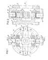
- an input axis 12denotes a rotatable drive member.
- the drive memberhas a flange 14 and a fork-shaped extension 16 with two legs 18 and 20.
- An output member 22includes a flange 24 and also a fork-shaped extension 26 with two legs 28 and 30.
- An intermediate member 32is formed by a cross body with two mutually perpendicular pairs of diametrically opposed bearing pins 34, 36 and 38, 40, respectively.
- the intermediate member 32is mounted with the first pair of trunnions 34, 36 in the fork-shaped extension 16 of the drive member 10 so as to be rotatable about a first axis 42.
- storagetakes place by means of bearing bushes 44, 46. Instead, rolling bearings can also be provided.
- the second pair of journals 38 and 40protrude radially beyond the first pair 34, 36.
- the intermediate member 32 and the fork-shaped extension 16are surrounded by a ring 48.
- This ring 48is rotatably mounted on the second pair of trunnions 38, 40 via bearing bushes 50, 52 about a second axis 54 which is perpendicular to the first axis 42.
- the ring 48is in turn rotatably supported with bearing bushes 56, 58 on bearing journals 60, 62 which project in radial alignment from the two legs 28 and 30 of the fork-shaped extension 26 of the output member 22.
- the ring 48can be rotated about a third axis 64 relative to the output member 26, which is perpendicular to the output axis 66, about which the output member 26 rotates, and perpendicular to the second axis 54.
- both the first axis 42 and the third axis 64are always in a common plane which is perpendicular to the second axis 54. There is therefore a homokinetic transmission of the drive movement.
- the jointas shown in FIGS. 1 and 2, is however undetermined, so that additional means must be provided which determine the position of the ring 48.
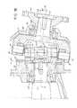
- FIGS. 3 to 7A joint of this type, which allows a change in the angular offset between the input shaft and the output shaft, is shown in FIGS. 3 to 7.
- the basic structure of this jointis the same as in ig F. 1 and 2, and corresponding parts are therefore provided with the same reference numerals as there.
- the second bevel gear 72forms a body of rectangular basic shape, which has the bevel gears only on the two arc-shaped narrow sides 88, 90.
- the bevel gear 72is connected to a ring 94 via an arm 92 which extends in the middle of one longitudinal side and approximately parallel to the axis of the Keqelrad 72.
- the ring 94is supported with a bearing bush 96 within an opening 98 of the first bevel gear 68 on the bearing journal 36.
- the arm 92carries a guide piece 76 which extends radially to the axis of the bevel gear 72 and, as can be seen in FIG. 6 is rectangular in cross section.
- the arm 92is seated in a sector-shaped cutout 102 of the bevel gear 68, as can best be seen from FIG. 5.
- the bevel gear 68can rotate relative to the bevel gear 72 within a limited angular range.
- the guide piece 76is held in the guide 78.
- the bevel gear 72When the driven member 22 bends relative to the drive member 10, which is considered to be stationary, about a vertical axis in FIG. 4 lying in the paper plane, the bevel gear 72 is also rotated by the guide 78.
- the bevel gear 72rotates the two bevel gears 80 and 82 in opposite directions, as a result of which they "run up” or “down” on the fixed bevel gear 68, whereby the ring 48 is rotated about the axis 42 by half the swivel angle between the input and output axes.
- a rotation of the output member 22 about an axis perpendicular to the paper planeis permitted by the guide piece 76 in the guide 78.
- the ring 48is rotated in a corresponding manner via the pins 60 and 62.
- the ring 48rotates on the pins 38 and 40.
- the rectangular guide piece 76is replaced by a circular pin 100 which is guided in the guide 78 via a roller bearing 104.
- FIGS. 11 to 18show a constant velocity joint which is set up for a fixed angular offset between the input axis and the output axis. Also in this joint, the basic structure is the same as in the joint according to FIGS. 1 and 2, so that the same reference numerals are used for corresponding parts be like there.
- sliding shoes 106 and 108are each rotatably mounted on the bearing pins 38 and 40 of the second pair.
- each slide shoehas a plane surface 110 that runs parallel to the second axis 54.
- This flat surface 110is provided on an arm 112, which extends parallel to the second axis 54 around the ring 48 and on the intended bearing for the bearing pin 38.
- the arm 112has a concave-cylindrical inner surface 114 which abuts the outer surface of the bearing 116.
- the sliding shoes 106, 108lie with the flat surfaces 110 on a sliding ring 118, which forms a flat contact surface and is provided on a housing 120.
- the normal of the flat stop surfacecoincides with the bisector between the input axis 12 and the output axis 66. For example, if, as shown, the angle between the input and output axes is 8 °, then the inclination of the flat contact surface is 4 °. Parallel to this flat contact surface, the ring 48 is also set due to the sliding shoes by pivoting about the axis 42.
- the drive member 10is connected to a shaft 122 which is mounted in the housing 120 via roller bearings 124.
- the connectionis made by means of a clamping piece 126, which is tightened by a screw 128, which is screwed into the end face of the shaft 122, against the right end face of the drive member 110 in the figure.
- the left end surface in the figure of the drive g song 110is pressed to the inner race of the rolling bearing 124th
- the output member 22is supported by a roller bearing 130 in a housing 132 so that the output axis 66 forms a fixed angle of 8 ° with the input axis 12.
- An output flange 134which is mounted in the housing 132 via a ball bearing 136, is tightened against the inner ring of the roller bearing 130 by means of a pressure piece 138.
- the pressure piece 138is tightened by means of a screw 140 which is seated in the end face of the driven member 22.
- all swivel bearingscontain as a means for determining the position of the ring a rubber-elastic mass which is vulcanized between a bearing journal and a bearing sleeve surrounding it at a distance, so that it is subjected to torsion upon rotation.
- the bearing pinsare spherical and are surrounded by hollow spherical bearing sleeves.
- the spherical bearing journals 34 and 36 of the intermediate member 32are connected to the hollow spherical-segment-shaped bearing surfaces 146 and 148, respectively, by vulcanized rubber compounds 142 and 144, which are formed in the legs 18 and 20 of the fork-shaped extension 16 of the drive member 10.
- the spherical bearing journals 38 and 40are connected to the bearing surfaces 154 and 156 of the ring 48 by means of rubber masses 150; 152.
- the ring 48is provided with bearing surfaces 158 and 160 which are in the form of hollow spheres and surround the spherical bearing journals 60 and 62 and are connected to these by means of rubber compounds 162 and 164, respectively.
- a drive member 168 rotatable about an input axis 166has bearing journals 170, 172 which extend radially outward from a fork-shaped extension 174 with legs 176, 178.
- the pins 170 and 172are arranged diametrically opposite and in alignment. They define a first axis 180 perpendicular to the drive axis 166.
- the intermediate link 182is a ring with two mutually perpendicular pairs of diametrically opposed bearings 184, 186 and 188, 190. With the first pair of bearings 184, 186, the intermediate member 182 is rotatably mounted about bearing pins 170, 172 on the bearing journals 170 and 172 about the first axis 180.
- the intermediate link 182is supported on a shaft 196.
- the shaftextends along the second axis 198 diametrically through the intermediate member 182 and with play through the fork-shaped projection 174 between its two legs 176 ′ and 178.
- the shaft 196projects radially beyond the annular intermediate member 182.
- the ring 204 surrounding the intermediate member 182is rotatably supported on the ends 200 and 202 of the shaft 196 about the second axis 198.
- the ring 204is in turn mounted about the third axis 206 in a fork-shaped extension 208 of an output member 210.
- the legs 212 and 214 of the fork-shaped extension 208 radially inwardly projecting pins 216 and 218are provided, on which the ring 204 is supported with bearings 220 and 222 via bushings 224 and 226.
- the bearings and trunnionscan be elastically bound by rubber compound in a similar manner as in FIGS. 19 and 20. In the embodiment according to FIGS. 21 and 22, this has the advantage that the same number of rubber-elastic bearings is present in both buckling directions.
- the drive and / or driven membercan contain a coupling that is elastic in the circumferential direction.
- An example of such an elastic couplingis shown in FIGS. 23 and 24.
- the clutch 228contains a clutch drive member 230 and a clutch drive member 232.
- On the clutch drive memberfour bolts 236, 238, 240 and 242 are each arranged at 90 ° to one another on a circular arc around its axis 234.
- Each boltcarries an oval pressure body 244, 246, 248 or 250, the longitudinal axis of the oval pressure body running radially. With these pressure elements, the bolts are arranged in cylindrical recesses 252, 254, 256 and 258 of the clutch output element 232.
- An elastic rubber compound 260, 262, 264, 266is vulcanized in between the inner wall of the recesses 252 to 258 and the pressure elements 244 to 250.
Landscapes
- Engineering & Computer Science (AREA)
- General Engineering & Computer Science (AREA)
- Mechanical Engineering (AREA)
- Axle Suspensions And Sidecars For Cycles (AREA)
- Support Of The Bearing (AREA)
- Gear Transmission (AREA)
- Friction Gearing (AREA)
Abstract
Description
Translated fromGermanDie Erfindung betrifft ein homokinetisches Gelenk, enthaltend: ein um eine Eingangsachse drehbares Antriebsglied, ein Zwischenglied, das um eine zu derEingangsachse senkrechte erste Achse verdrehbar an dem Antriebsglied angelenkt ist, ein um eine Ausgangsachse drehbares Abtriebsglied und Kupplungsmittel zwischen dem Zwischenglied und dem Abtriebsglied, welche einerseits um eine zu der ersten Achse senkrechte zweite Achse verdrehbar an dem Zwischenglied und andererseits um eine zu der Ausgangsachse senkrechte dritte Achse verdrehbar an dem Abtriebsglied angelenkt sind.The invention relates to a constant velocity joint, comprising: a rotatable about an input axis drive member, an intermediate member which is articulated about a ingangsachse to theE perpendicular first axis rotatably on the drive member, a rotatable about an output axis driven member and coupling means between the intermediate member and the output member which, on the one hand, are articulated on the intermediate member about a second axis perpendicular to the first axis and, on the other hand, are articulated on the output member about a third axis perpendicular to the output axis.
Zur Übertragung einer Drehbewegung von einem um eine Eingangsachse rotierenden Eingangsglied auf ein Ausgangsglied, das um eine gegenüber der Eingangsachse winkelversetzte Ausgangsachse umläuft, sind Kardangelenke bekannt. Übliche Kardangelenke enthalten einen Kreuzkörper mit zwei Paaren von senkrecht zueinander angeordneten Lagerzapfen. Mit einem Paar von Lagerzapfen ist der Kreuzkörper um eine erste, zur Eingangsachse senkrechte Achse in einem gabelförmigen Ansatz des Antriebsgliedes verdrehbar gelagert. Das Abtriebsglied ist mit einem entsprechenden gabelförmigen Ansatz auf dem anderen Paar von Lagerzapfen des Kreuzkörpers gelagert, die eine Verdrehung um eine zweite, zu der ersten Achse senkrechte Achse gestatten. Ein solches Kardangelenk hat den Nachteil, daß es nicht homokinetisch ist, d.h. eine gleichförmige Drehbewegung des Antriebsgliedes wird in eine ungleichförmige Drehbewegung des Abtriebsgliedes umgesetzt, wenn Eingangsachse und Ausgangsachse einen Winkel miteinander einschließen.For transmitting a rotary motion from a rotating about an input axis input member to an output member that rotates about a longitudinal axis relative to the Ag angularly displaced output axis, universal joints are known. Usual universal joints contain a cross body with two pairs of trunnions arranged perpendicular to each other. With a pair of bearing journals, the cross body is in a fork-shaped approach about a first axis perpendicular to the input axis of the drive member rotatably mounted. The output member is mounted with a corresponding fork-shaped projection on the other pair of trunnions of the cross body, which allow rotation about a second axis perpendicular to the first axis. Such a universal joint has the disadvantage that it is not homokinetic, ie a uniform rotational movement of the drive member is converted into a non-uniform rotational movement of the driven member if the input axis and the output axis form an angle with one another.
Es ist daher bekannt, zwei derartige Kardangelenke über eine Zwischenwelle hintereinanderzuschalten, wobei der Winkel zwischen Eingangsachse und Umlaufachse der Zwischenwelle genau so groß gewählt wird wie der Winkel zwischen der Umlaufachse der Zwischenwelle und der Ausgangsachse.It is therefore known to connect two such universal joints in series via an intermediate shaft, the angle between the input axis and the circumferential axis of the intermediate shaft being chosen to be exactly as large as the angle between the circumferential axis of the intermediate shaft and the output axis.
Eine solche Anordnung ist relativ aufwendig und erfordert erheblichen Raum.Such an arrangement is relatively complex and requires considerable space.
Der Erfindung liegt die Aufgabe zugrunde, ein homokinetisches Gelenk der eingangs definierten Art in einfacher und raumsparender Weise aufzubauen.The invention has for its object to build a homokinetic joint of the type defined in a simple and space-saving manner.
Erfindungsgemäß wird diese Aufgabe dadurch gelöst, daß die Kupplungsmittel von einem Ring gebildet sind, welcher das Zwischenglied umgibt, daß die dritte Achse, um welche dieser Ring verdrehbar an dem Abtriebsglied gelagert ist senkrecht zu der zweiten Achse verläuft und daß Mittel zur Festlegung der Lage des Ringes vorgesehen sind.According to the invention this object is achieved in that the coupling means are formed by a ring which surrounds the intermediate member, that the third axis about which this ring is rotatably mounted on the output member is perpendicular to the second axis and that means for determining the position of the Ring are provided.
Durch die Verwendung des Ringes wird erreicht, daß sich während des Umlaufs die dritte Achse stets genau in der gleichen, zu der zweiten Achse senkrechten Ebene befindet wie die erste Achse, so daß eine homokinetische Bewegungsübertragung gewährleistet ist. Der Ring mit seiner Lagerung bringt einen zusätzlichen Freiheitsgrad, so daß das System unterbestimmt ist. Diese Unterbestimmung wird durch Mittel zur Festlegung der Lage des Ringes beseitigt. Die Festlegung kann dabei kinematisch oder aber auch dynamisch erfolgen.The use of the ring ensures that the third axis is always exactly in the same plane perpendicular to the second axis as the first axis during the rotation, so that a homokinetic transmission of movement is ensured. The ring with its bearing brings an additional degree of freedom, so that the system is undefined. This sub-determination is eliminated by means of determining the position of the ring. The determination can be made kinematically or dynamically.
Weitere Ausgestaltungen der Erfindung sind Gegenstand der Unteransprüche.Further embodiments of the invention are the subject of the dependent claims.
Die Erfindung ist nachstehend an einigen Ausführungsbeispielen unter Bezugnahme auf die zugehörigen Zeichnungen näher erläutert:
- Fig. 1 zeigt eine Längsansicht eines homokinetischen Gelenks.
- Fig. 2 zeigt einen Schnitt längs der Linie A-B von Fig. 1.
- Fig. 3 zeigt eine Ansicht ähnlich Fig. 1 eines homokinetischen Gelenks, welches für variable Winkel zwischen Eingangsachse und Ausgangsachse geeignet ist.
- Fig. 4 zeigt einen Schnitt längs der Linie C-D von Fig. 3.
- Fig. 5 zeigt eine bei dem Gelenk von Fig. 3 und 4 verwendete Kegelradanordnung in einer Ansicht in Richtung des Pfeils B von Fig. 6.
- Fig. 6 zeigt eine Ansicht, teilweise im Schnitt, der Kegelanordnung in Richtung des Pfeils A von Fig. 5.
- Fig. 7 zeigt einen Schnitt längs der Linie VII-VII von Fig. 6.
- Fig. 8 zeigt einen Schnitt längs der Linie E-F von Fig. 7.
- Fig. 9 zeigt eine abgewandelte Ausführungsform in einer Darstellung ähnlich Fig. 7.
- Fig. 10 zeigt diese Ausführungsform in einer Darstellung ähnlich Fig. 8.
- Fig. 11 zeigt eine Längsansicht eines Gelenks, welches für einen festen Winkelversatz zwischen Eingangsachse und Ausgangsachse eingerichtet ist.
- Fig. 12 zeigt eine abgebrochene Ansicht in Richtung des Pfeils X von Fig. 11.
- Fig. 13 zeigt einen Schnitt längs der Linie J-K von Fig. 12.
- Fig. 14 zeigt im einzelnen einen bei der Konstruktion von Fig. 11 verwendeten Gleitschuh.
- Fig. 15 zeigt einen Schnitt längs der Linie L-M von Fig. 14.
- Fig. 16 ist eine Ansicht von links in Fig. 14.
- Fig. 17 zeigt einen Schnitt längs der Linie XVII-XVII von Fig. 11.
- Fig. 18 zeigt das Gelenk nach einer Verdrehung von 90 gegenüber der Stellung von Fig. 17.
- Fig. 19 zeigt in einer Längsansicht, teilweise im Schnitt, eine abgewandelte Ausführungsform, bei welcher die Teile in den Gelenken durch Gummimassen elastisch aneinander gefesselt sind, so daß die Festlegung der Lage des Ringes dynamisch durch Rückstellkräfte erfolgt.
- Fig. 20 zeigt einen Längsschnitt durch das Gelenk von Fig. 19.
- Fig. 21 zeigt eine weitere Ausführungsform eines homokinetischen Gelenks.
- Fig. 22 zeigt einen Längsschnitt durch das Gelenk von Fig. 21.
- Fig. 23 zeigt in einem Längsschnitt eine in Umfangsrichtung elastische Kupplung, die zusätzlich in einem Gelenk der vorliegenden Art vorgesehen werden kann.
- Fig. 24 ist eineSchnitt längs der Linie XXIV-XXIV von Fig. 23.
- Fig. 1 shows a longitudinal view of a constant velocity joint.
- FIG. 2 shows a section along the line AB from FIG. 1.
- FIG. 3 shows a view similar to FIG. 1 of a homokinetic joint which is suitable for variable angles between the input axis and the output axis.
- FIG. 4 shows a section along the line CD from FIG. 3.
- FIG. 5 shows a bevel gear arrangement used in the joint of FIGS. 3 and 4 in a view in the direction of arrow B of FIG. 6.
- F ig. 6 shows a view, partly in section, of the cone arrangement in the direction of arrow A of FIG. 5.
- FIG. 7 shows a section along the line VII-VII of FIG. 6.
- FIG. 8 shows a section along the line EF from FIG. 7.
- FIG. 9 shows a modified embodiment in a representation similar to FIG. 7.
- FIG. 10 shows this embodiment in a representation similar to FIG. 8.
- 11 shows a longitudinal view of a joint which is set up for a fixed angular offset between the input axis and the output axis.
- FIG. 12 shows a broken view in the direction of arrow X in FIG. 11.
- FIG. 13 shows a section along the line JK of FIG. 12.
- Fig. 14 shows in detail a slide shoe used in the construction of Fig. 11.
- FIG. 15 shows a section along the line LM from FIG. 14.
- FIG. 16 is a left view in FIG. 14.
- FIG. 17 shows a section along the line XVII-XVII of FIG. 11.
- F ig. 18 shows the joint after a rotation of 90 relative to the position of FIG. 17.
- Fig. 19 shows in a longitudinal view, partly in section, a modified embodiment in which the parts in the joints are elastically bound together by rubber compounds, so that the position of the ring is determined dynamically by restoring forces.
- 20 shows a longitudinal section through the joint of FIG. 19.
- F ig. 21 shows another embodiment of a homokinetic joint.
- 22 shows a longitudinal section through the joint of FIG. 21.
- F ig. 23 shows a longitudinal section of a coupling which is elastic in the circumferential direction and can additionally be provided in a joint of the present type.
- Fig. 24 is a section along the line XXIV-XXIV of Fig. 23.
In Fig. 1 und 2 ist mit 10 ein ur. eine Eingangsachse 12 drehbares Antriebsglied bezeichnet. Das Antriebsglied weist bei dem Ausführungsbeispiel einen Flansch 14 und einen gabelförmigen Ansatz 16 mit zwei Schenkeln 18 und 20 auf.1 and 2 with 10 is a ur. an
Ein Abtriebsglied 22 enthält einen Flansch 24 sowie ebenfalls einen gabelförmigen Ansatz 26 mit zwei Schenkeln 28 und 30. Ein Zwischenglied 32 wird von einem Kreuzkörper mit zwei zueinander senkrechten Paaren von diametral einander gegenüberliegenden Lagerzapfen 34,36 bzw. 38,40 gebildet. Das Zwischenglied 32 ist mit dem ersten Paar von Lagerzapfen 34,36 in dem gabelförmigen Ansatz 16 des Antriebsgliedes 10 um eine erste Achse 42 verdrehbar gelagert. Die Lagerung erfolgt bei dem dargestellten Ausführungsbeispiel mittels Lagerbuchsen 44,46. Stattdessen können aber auch Wälzlager vorgesehen sein.An
Das zweite Paar von Lagerzapfen 38 und 40 ragt radial über das erste Paar 34,36 hinaus. Das Zwischenglied 32 und der gabelförmige Ansatz 16 sind von einem Ring 48 umgeben. Dieser Ring 48 ist auf dem zweiten Paar von Lagerzapfen 38,40 über Lagerbuchsen 50,52 um eine zweite, zu der ersten Achse 42 senkrechte Achse 54 verdrehbar gelagert. Der Ring 48 ist wiederum mit Lagerbuchsen 56,58 auf Lagerzapfen 60,62 drehbar gelagert, die fluchtend von den beiden Schenkeln 28 und 30 des gabelförmigen Ansatzes 26 des Abtriebsgliedes 22 radial einwärts ragen. Dadurch ist der Ring 48 um eine dritte Achse 64 relativ zu dem Abtriebsglied 26 verdrehbar, die senkrecht zu der Ausgangsachse 66, um welche das Abtriebsglied 26 rotiert, und senkrecht zu der zweiten Achse 54 verläuft.The second pair of
Es ist erkennbar, daß sowohl die erste Achse 42 als auch die dritte Achse 64 stets in einer gemeinsamen Ebene liegen, die jeweils senkrecht zu der zweiten Achse 54 verläuft. Es erfolgt daher eine homokinetische Übertragung der Antriebsbewegung.It can be seen that both the
Das Gelenk, wie es in Fig. 1 und 2 dargestellt ist, ist jedoch unterbestimmt, so daß zusätzliche Mittel vorgesehen werden müssen, welche die Lage des Ringes 48 festlegen.The joint, as shown in FIGS. 1 and 2, is however undetermined, so that additional means must be provided which determine the position of the
Ein Gelenk dieser Art, welches eine Veränderung des Winkelversatzes zwischen Eingangswelle und Ausgangswelle gestattet, ist in den Figuren 3 bis 7 dargestellt. Der Grundaufbau dieses Gelenks ist der gleiche wie inFig. 1 und 2, und entsprechende Teile sind daher mit den gleichen Bezugszeichen versehen wie dort.A joint of this type, which allows a change in the angular offset between the input shaft and the output shaft, is shown in FIGS. 3 to 7. The basic structure of this joint is the same as in
Zur Festlegung der Lage des Ringes 48 sind folgende Bauteile vorgesehen:
Ein erstes Kegelrad 68 ist auf dem einen Lagerzapfen 36 des ersten Paares gelagert undmit dem Schenkel 20 des gabelförmigen Ansatzes 16durch Schrauben 70 fest verbunden.Ein zweites Kegelrad 72 ist mit einerLagerbuchse 74 drehbar auf dem anderen Lagerzapfen 34 des ersten Paares gelagert undmit einem Führungsstück 76 verbunden.Das Führungsstück 76 gleitet in einer indem Abtriebsglied 22vorgesehenen Führung 78, die in einer durch die erste Achse 42 gehenden Ebene verläuft und eine Schwenkbewegung um diezweite Achse 54 zuläßt. Ein drittes und viertes Kegelrad 80 und 82 sindmit Lagerbuchsen 84 bzw. 86 drehbar auf den beidenLagerzapfen 38 und 40 des zweiten Paares gelagert und stehen mit dem ersten und dem zweiten Kegelrad 68 und 72 in Eingriff.
- A
first bevel gear 68 is mounted on the onejournal 36 of the first pair and is firmly connected to theleg 20 of the fork-shapedextension 16 byscrews 70. Asecond bevel gear 72 is rotatably supported by a bearingbush 74 on theother journal 34 of the first pair and connected to aguide piece 76. Theguide piece 76 slides in aguide 78 provided in the drivenmember 22, which runs in a plane passing through thefirst axis 42 and allows a pivoting movement about thesecond axis 54. A third and fourth bevel gear 80 and 82 are rotatably supported on the two bearingjournals bushings
Wie am besten aus den Figuren 5 bis 7 ersichtlich ist, bildet das zweite Kegelrad 72 einen Körper von rechteckiger Grundform, der die Kegelverzahnungen nur an den beiden kreisbogenförmigen Schmalseiten 88,90 aufweist. Das Kegelrad 72 ist über einen in der Mitte der einen Längsseite sich etwa parallel zur Achse des Keqelrads 72 erstreckenden Arm 92 mit einem Ring 94 verbunden. Der Ring 94 ist mit einer Lagerbuchse 96 innerhalb eines Durchbruchs 98 des ersten Kegelrads 68 auf dem Lagerzapfen 36 gelagert. Der Arm 92 trägt ein Führungsstück 76, das sich radial zu der Achse des Kegelrads 72 erstreckt und, wie aus Fig. 6 ersichtlich ist, rechteckigen Querschnitt besitzt. Der Arm 92 sitzt in einem sektorförmigen Ausschnitt 102 des Kegelrades 68, wie am besten aus Fig. 5 ersichtlich ist. Infolgedessen kann sich das Kegelrad 68 in einem begrenzten Winkelbereich relativ zu dem Kegelrad 72 verdrehen.As can best be seen from FIGS. 5 to 7, the
Das Führungsstück 76 ist, wie gesagt, in der Führung 78 gehalten.As mentioned, the
Bei einer Knickbewegung des Abtriebsgliedes 22 gegenüber dem als feststehend angesehenen Antriebsglied 10 um eine in der Papierebene liegende vertikale Achse in Fig. 4 wird durch die Führung 78 das Kegelrad 72 mit verdreht. Das Kegelrad 72 verdreht die beiden Kegelräder 80 und 82 gegensinnig, wodurch diese an dem feststehenden Kegelrad 68 "hinauf" bzw. "hinunterlaufen", wodurch der Ring 48 um den halben Schwenkwinkel zwischen Eingangs- und Ausgangsachse um die Achse 42 verdreht wird.When the driven
Eine Verdrehung des Abtriebsgliedes 22 um eine zur Papierebene senkrechte Achse wird durch das Führungsstück 76 in der Führung 78 zugelassen. Mit dem Ausgangsglied 22 wird der Ring 48 über die Zapfen 60 und 62 in entsprechender Weise verdreht. Der Ring 48 dreht sich dabei auf den Zapfen 38 und 40.A rotation of the
Bei der Ausführungsform nach Fig. 9 und 10 ist das rechteckige Führungsstück 76 durch einen kreisrunden Zapfen 100 ersetzt, welcher über ein Rollenlager 104 in der Führung 78 geführt ist.In the embodiment according to FIGS. 9 and 10, the
Die Figuren 11 bis 18 zeigen ein homokinetisches Gelenk, welches für einen festen Winkelversatz zwischen Eingangsachse und Ausgangsachse eingerichtet ist. Auch bei diesem Gelenk ist der Grundaufbau der gleiche wie bei dem Gelenk nach Fig. 1 und 2, so daß für entsprechende Teile die gleichen Bezugszeichen benutzt werden wie dort.FIGS. 11 to 18 show a constant velocity joint which is set up for a fixed angular offset between the input axis and the output axis. Also in this joint, the basic structure is the same as in the joint according to FIGS. 1 and 2, so that the same reference numerals are used for corresponding parts be like there.
Bei der Ausführungsform nach Fig. 11 bis 18 sind auf den Lagerzapfen 38 und 40 des zweiten Paares je ein Gleitschuh 106 bzw. 108 drehbar gelagert. Wie aus Fig. 13 am besten ersichtlich ist, weist jeder Gleitschuh eine parallel zu der zweiten Achse 54 verlaufende Planfläche 110-auf. Diese Planfläche 110 ist an einem Arm 112 vorgesehen, der sich parallel zu der zweiten Achse 54 um den Ring 48 und das an dem vorgesehenen Lager für den Lagerzapfen 38 herumerstreckt. Der Arm 112 weist eine konkav-zylindrische Innenfläche 114 auf, die an der Außenfläche des Lagers 116 anliegt.In the embodiment according to FIGS. 11 to 18, sliding
Wie aus Fig. 17 ersichtlich ist, liegen die Gleitschuhe 106,108 mit den Planflächen 110 an einem Gleitring 118 an, der eine ebene Anlagefläche bildet und an einem Gehäuse 120 vorgesehen ist. Die Normale der ebenen Anschlagfläche fällt mit der Winkelhalbierenden zwischen Eingangsachse 12 und Ausgangsachse 66 zusammen. Wenn beispielsweise, wie dargestellt, der Winkel zwischen Eingangs- und Ausgangsachse 8° beträgt, dann ist die Neigung der ebenen Anlagefläche 4°. Parallel zu dieser ebenen Anlagefläche stellt sich infolge der Gleitschuhe auch der Ring 48 durch Verschwenkung um die Achse 42 ein.As can be seen from FIG. 17, the sliding
Bei der Ausführungsform nach Fig. 17 ist das Antriebsglied 10 mit einer Welle 122 verbunden, die über Rollenlager 124 in dem Gehäuse 120 gelagert ist. Die Verbindung erfolgt mittels eines Klemmstücks 126, das durch eine Schraube 128, die in die Stirnfläche der Welle 122 eingeschraubt ist, gegen die in der Figur rechte Stirnfläche des Antriebsglieds 110 festgezogen wird. Die in der Figur linke Stirnfläche des Antriebsglieds 110 wird dabei an den inneren Laufring des Wälzlagers 124 gedrückt. Das Abtriebsglied 22 ist durch ein Wälzlager 130 in einem Gehäuse 132 so gelagert, daß die Ausgangsachse 66 mit der Eingangsachse 12 einen festen Winkel von 8° bildet. Ein Abtriebsflansch 134, der über ein Kugellager 136 im Gehäuse 132 gelagert ist, ist mittels eines Druckstücks 138 gegen den Innenring des Wälzlagers 130 festgezogen. Das Druckstück 138 wird mittels einer Schraube 140, die in der Stirnfläche des Abtriebsglieds 22 sitzt, festgezogen.In the embodiment according to FIG. 17, the
Bei der Ausführungsform nach Fig. 19 und 20 sind die Drehlager durch gummielastische Verbindungen ersetzt, die eine elastische Relativverdrehung der einzelnen Teile gegeneinander zulassen. Hierdurch ist die Lage des Ringes 48 "dynamisch", d.h. durch die elastischen Rückstellkräfte festgelegt. Auch in diesen Figuren sind für entsprechende Teile die gleichen Bezugszeichen benutzt wie in Fig. 1.In the embodiment according to FIGS. 19 and 20, the rotary bearings are replaced by rubber-elastic connections which permit an elastic relative rotation of the individual parts against one another. As a result, the position of the
Bei der Ausführungsform nach der Fig. 19 und 20 enthalten als Mittel zur Festlegung der Lage des Ringes alle Schwenklager eine gummielastische Masse, die zwischen einem Lagerzapfen und einer diesen mit Abstand umgebenden Lagerhülse einvulkanisiert ist, so daß sie bei einer Verdrehung auf Torsion beansprucht wird. Dabei sind die Lagerzapfen ballig ausgebildet und sind von hohlkugelabschnittförmigen Lagerhülsen umgeben.In the embodiment according to FIGS. 19 and 20, all swivel bearings contain as a means for determining the position of the ring a rubber-elastic mass which is vulcanized between a bearing journal and a bearing sleeve surrounding it at a distance, so that it is subjected to torsion upon rotation. The bearing pins are spherical and are surrounded by hollow spherical bearing sleeves.
Im einzelnen sind die ballig ausgebildeten Lagerzapfen 34 und 36 des Zwischengliedes 32 über einvulkanisierte Gummimassen 142 bzw. 144 mit den hohlkugelabschnittförmigen Lagerflächen 146 bzw. 148 verbunden, die.in den Schenkeln 18 und 20 des gabelförmigen Ansatzes 16 des Antriebsgliedes 10 gebildet sind.In detail, the
Die ballig ausgebildeten Lagerzapfen 38 und 40 sind über Gummimassen 150;152 mit den hohlkugelabschnittförmigen Lagerflächen 154 bzw. 156 des Ringes 48 verbunden. Schließlich ist der Ring 48 mit hohlkugelabschnittförmigen Lagerflächen 158 bzw. 160 versehen, welche die ballig ausgebildeten Lagerzapfen 60 und 62 umgeben und mit diesen über Gummimassen 162 bzw. 164 verbunden sind.The
Bei dem Ausführungsbeispiel nach Fig. 21 und Fig. 22 ist eine andere Form des Zwischenglieds gewählt.In the embodiment according to FIGS. 21 and 22, a different shape of the intermediate member is chosen.
Ein um eine Eingangsachse 166 drehbares Antriebsglied 168 weist Lagerzapfen 170,172 auf, die sich von einem gabelförmigen Ansatz 174 mit Schenkeln 176,178 radial nach außen erstrecken. Die Zapfen 170 und 172 sind dabei diametral einander gegenüberliegend und fluchtend angeordnet. Sie definieren eine zu der Antriebsachse 166 senkrechte erste Achse 180. Das Zwischenglied 182 ist ein Ring mit zwei zueinander senkrechten Paaren von diametral einander gegenüberliegenden Lagern 184,186 bzw. 188,190. Mit dem ersten Paar von Lagern 184,186 ist das Zwischenglied 182 über Lagerbuchsen 192,194 auf den Lagerzapfen 170 bzw. 172 um die erste Achse,180 verdrehbar gelagert. Mit dem zweiten Paar von Lagern 188,190 ist das Zwischenglied 182 auf einer Welle 196 gelagert. Die Welle erstreckt sich längs der zweiten Achse 198 diametral durch das Zwischenglied 182 und mit Spiel durch den gabelförmigen Ansatz 174 zwischen dessen beiden Schenkeln 176'und 178. Mit ihren Enden 200,202 ragt die Welle 196 radial über das ringförmige Zwischenglied 182 hinaus. Der das Zwischenglied 182 umgebende Ring 204 ist auf den Enden 200 und 202 der Welle 196 um die zweite Achse 198 verdrehbar gelagert. Der Ring 204 ist wiederum um die dritte Achse 206 in einem gabelförmigen Ansatz 208 eines Abtriebsgliedes 210 gelagert. Zu diesem Zweck sind an den Schenkeln 212 und 214 des gabelförmigen Ansatzes 208 radial nach innen ragende Zapfen 216 bzw. 218 vorgesehen, auf denen der Ring 204 mit Lagern 220 und 222 über Lagerbuchsen 224 und 226 gelagert ist. Die Lager und Lagerzapfen können in ähnlicher Weise wie in Fig. 19 und 20 durch Gummimasse elastisch gefesselt sein. Dies hat bei der Ausführungsform nach Fig. 21 und Fig. 22 den Vorteil, daß in beiden Knickrichtungen die gleiche Anzahl von gummielastischen Lagern vorhanden ist.A
Das Antriebs- und/oder Abtriebsglied kann eine in Umfangsrichtung elastische Kupplung enthalten. Ein Beispiel für eine solche elastische Kupplung ist in den Figuren 23 und 24 dargestellt.The drive and / or driven member can contain a coupling that is elastic in the circumferential direction. An example of such an elastic coupling is shown in FIGS. 23 and 24.
Die Kupplung 228 enthält ein Kupplungsantriebsglied 230 und ein Kupplungsabtriebsglied 232. An dem Kupplungsantriebsglied sind auf einem Kreisbogen um dessen Achse 234 herum vier Bolzen 236,238,240 und 242 jeweils um 90° gegeneinander winkelversetzt angeordnet. Jeder Bolzen trägt einen ovalen Druckkörper 244,246,248 bzw. 250, wobei die Längsachse des ovalen Druckkörpers jeweils radial verläuft. Mit diesen Druckkörpern sind die Bolzen in zylindrischen Ausnehmungen 252,254,256 bzw. 258 des Kupplungsabtriebsgliedes 232 angeordnet. Zwischen der Innenwandung der Ausnehmungen 252 bis 258 und den Druckkörpern 244 bis 250 ist jeweils eine elastische Gummimasse 260,262,264,266 einvulkanisiert.The clutch 228 contains a
Claims (9)
Translated fromGermanApplications Claiming Priority (2)
| Application Number | Priority Date | Filing Date | Title |
|---|---|---|---|
| DE2850301 | 1978-11-20 | ||
| DE19782850301DE2850301A1 (en) | 1978-11-20 | 1978-11-20 | HOMOKINETIC JOINT |
Publications (1)
| Publication Number | Publication Date |
|---|---|
| EP0011159A1true EP0011159A1 (en) | 1980-05-28 |
Family
ID=6055152
Family Applications (1)
| Application Number | Title | Priority Date | Filing Date |
|---|---|---|---|
| EP79104102AWithdrawnEP0011159A1 (en) | 1978-11-20 | 1979-10-23 | Homokinetic joint |
Country Status (6)
| Country | Link |
|---|---|
| EP (1) | EP0011159A1 (en) |
| JP (1) | JPS5572922A (en) |
| BR (1) | BR7907481A (en) |
| DD (1) | DD147272A5 (en) |
| DE (1) | DE2850301A1 (en) |
| ES (1) | ES486120A1 (en) |
Cited By (4)
| Publication number | Priority date | Publication date | Assignee | Title |
|---|---|---|---|---|
| EP0560058A3 (en)* | 1992-03-07 | 1994-05-04 | Lemfoerder Metallwaren Ag | |
| EP0860622A1 (en)* | 1997-02-19 | 1998-08-26 | Yordak Ltd | A constant velocity joint |
| RU2215207C2 (en)* | 2001-03-26 | 2003-10-27 | Белгородская государственная сельскохозяйственная академия | Cardan |
| GB2422885A (en)* | 2005-02-08 | 2006-08-09 | Cecil Walter Schumacher | Double cardan joint with coincident crosses |
Families Citing this family (4)
| Publication number | Priority date | Publication date | Assignee | Title |
|---|---|---|---|---|
| DE3205715A1 (en)* | 1982-02-18 | 1983-08-25 | Ilie 4690 Herne Chivari | DOUBLE CROSS JOINT |
| WO1983002984A1 (en)* | 1982-02-18 | 1983-09-01 | Ilie Chivari | Universal joint |
| DE4024625A1 (en)* | 1990-08-03 | 1992-02-06 | Renk Ag | Twin-shaft cardan joint system - has ring bearing set coaxially between two engaging end sections of two shafts |
| CN102152303B (en)* | 2011-03-08 | 2012-09-26 | 天津大学 | Reconfigurable Hooke joint |
Citations (5)
| Publication number | Priority date | Publication date | Assignee | Title |
|---|---|---|---|---|
| DE1292961B (en)* | 1962-08-03 | 1969-04-17 | Morse Chain Co | Elastic shaft coupling |
| US3456458A (en)* | 1966-05-04 | 1969-07-22 | Secr Defence Brit | Constant velocity joints |
| FR2185270A5 (en)* | 1972-05-12 | 1973-12-28 | Ehrenreich & Cie A | |
| FR2271444A1 (en)* | 1974-05-13 | 1975-12-12 | Glaenzer Spicer Sa | |
| DE2454011A1 (en)* | 1974-11-14 | 1976-05-26 | Emilio Nicoletti | Universal joint between two shafts - has auxiliary support joint fitting coaxially inside normal fork and ring connection= |
- 1978
- 1978-11-20DEDE19782850301patent/DE2850301A1/ennot_activeWithdrawn
- 1979
- 1979-10-23EPEP79104102Apatent/EP0011159A1/ennot_activeWithdrawn
- 1979-11-19ESES486120Apatent/ES486120A1/ennot_activeExpired
- 1979-11-19BRBR7907481Apatent/BR7907481A/enunknown
- 1979-11-19DDDD21699779Apatent/DD147272A5/enunknown
- 1979-11-20JPJP14963879Apatent/JPS5572922A/enactivePending
Patent Citations (5)
| Publication number | Priority date | Publication date | Assignee | Title |
|---|---|---|---|---|
| DE1292961B (en)* | 1962-08-03 | 1969-04-17 | Morse Chain Co | Elastic shaft coupling |
| US3456458A (en)* | 1966-05-04 | 1969-07-22 | Secr Defence Brit | Constant velocity joints |
| FR2185270A5 (en)* | 1972-05-12 | 1973-12-28 | Ehrenreich & Cie A | |
| FR2271444A1 (en)* | 1974-05-13 | 1975-12-12 | Glaenzer Spicer Sa | |
| DE2454011A1 (en)* | 1974-11-14 | 1976-05-26 | Emilio Nicoletti | Universal joint between two shafts - has auxiliary support joint fitting coaxially inside normal fork and ring connection= |
Cited By (7)
| Publication number | Priority date | Publication date | Assignee | Title |
|---|---|---|---|---|
| EP0560058A3 (en)* | 1992-03-07 | 1994-05-04 | Lemfoerder Metallwaren Ag | |
| EP0860622A1 (en)* | 1997-02-19 | 1998-08-26 | Yordak Ltd | A constant velocity joint |
| US5954586A (en)* | 1997-02-19 | 1999-09-21 | Yordak Ltd. | Constant velocity joint |
| US6203438B1 (en) | 1997-02-19 | 2001-03-20 | Yordack Ltd. | Constant velocity joint |
| RU2215207C2 (en)* | 2001-03-26 | 2003-10-27 | Белгородская государственная сельскохозяйственная академия | Cardan |
| GB2422885A (en)* | 2005-02-08 | 2006-08-09 | Cecil Walter Schumacher | Double cardan joint with coincident crosses |
| WO2006085072A1 (en)* | 2005-02-08 | 2006-08-17 | Cecil Walter Schumacher | Constant velocity universal joint |
Also Published As
| Publication number | Publication date |
|---|---|
| DE2850301A1 (en) | 1980-05-29 |
| DD147272A5 (en) | 1981-03-25 |
| ES486120A1 (en) | 1980-05-16 |
| JPS5572922A (en) | 1980-06-02 |
| BR7907481A (en) | 1980-08-05 |
Similar Documents
| Publication | Publication Date | Title |
|---|---|---|
| DE1675238A1 (en) | Coupling for transferring rotary movements true to the angle of rotation | |
| EP0035283B1 (en) | Shaft coupling | |
| DE3112543A1 (en) | COUPLING TO CONNECT TWO SHAFTS | |
| DE3007348A1 (en) | SHAFT COUPLING | |
| DE69231593T2 (en) | VIBRANT TRIPODE UNIFORM JOINT | |
| EP0011159A1 (en) | Homokinetic joint | |
| EP0121779B1 (en) | Articulated coupling | |
| DE2431383C2 (en) | Coupling for off-axis rotating shafts | |
| DE3732705A1 (en) | SHAFT COUPLING | |
| DE3347262A1 (en) | CV JOINT | |
| DE3519895A1 (en) | CLUTCH FOR COUPLING AXIS-RELATED MACHINE PARTS | |
| WO1986003563A1 (en) | Coupling for linking axially-displaced shafts | |
| DE2504950A1 (en) | Flexible coupling between rotating shafts - has formed spring wire loops with connecting bolts forming independent linkages | |
| DE424819C (en) | Movable coupling | |
| EP0306441A2 (en) | Shaft coupling | |
| DE10135347A1 (en) | Centered double universal joint | |
| DD150498A5 (en) | SHAFT CLUTCH | |
| EP0656999B1 (en) | Homokinetic coupling | |
| EP0122947A1 (en) | Universal joint | |
| EP0086864A1 (en) | Double universal joint | |
| DE2933722A1 (en) | Clutch for offset rotating shafts - has clutch halves connected via pivoted links and members to absorb axial forces | |
| DE3016267A1 (en) | Constant velocity joint for rotating shafts - has ball jointed links to accommodate relative radial and axial movement | |
| DE1172906B (en) | Homokinetic universal joint | |
| DE4123201C1 (en) | Clutch with three intermediate members - has radial arms connected by circumferential links | |
| DE3203139A1 (en) | ANGLE-MOVING CONSTANT JOINT |
Legal Events
| Date | Code | Title | Description |
|---|---|---|---|
| PUAI | Public reference made under article 153(3) epc to a published international application that has entered the european phase | Free format text:ORIGINAL CODE: 0009012 | |
| AK | Designated contracting states | Designated state(s):AT BE CH DE FR GB IT LU NL SE | |
| 17P | Request for examination filed | Effective date:19801128 | |
| STAA | Information on the status of an ep patent application or granted ep patent | Free format text:STATUS: THE APPLICATION HAS BEEN WITHDRAWN | |
| 18W | Application withdrawn | Withdrawal date:19810813 |