EP0010070B1 - Cathodic sputtering method for depositing an autolubricant coating of metallic chalcogenides onto substrates - Google Patents
Cathodic sputtering method for depositing an autolubricant coating of metallic chalcogenides onto substratesDownload PDFInfo
- Publication number
- EP0010070B1 EP0010070B1EP79810117AEP79810117AEP0010070B1EP 0010070 B1EP0010070 B1EP 0010070B1EP 79810117 AEP79810117 AEP 79810117AEP 79810117 AEP79810117 AEP 79810117AEP 0010070 B1EP0010070 B1EP 0010070B1
- Authority
- EP
- European Patent Office
- Prior art keywords
- target
- coating
- process according
- substrate
- cathode
- Prior art date
- Legal status (The legal status is an assumption and is not a legal conclusion. Google has not performed a legal analysis and makes no representation as to the accuracy of the status listed.)
- Expired
Links
- 239000000758substrateSubstances0.000titleclaimsabstractdescription39
- 238000000576coating methodMethods0.000titleclaimsabstractdescription32
- 238000004544sputter depositionMethods0.000titleclaimsabstractdescription20
- 239000011248coating agentSubstances0.000titleclaimsabstractdescription19
- 150000004770chalcogenidesChemical class0.000titleclaimsabstractdescription14
- 238000000151depositionMethods0.000titleclaimsdescription18
- 229910052751metalInorganic materials0.000claimsabstractdescription10
- 239000002184metalSubstances0.000claimsabstractdescription10
- 239000000203mixtureSubstances0.000claimsdescription37
- 238000000034methodMethods0.000claimsdescription33
- NINIDFKCEFEMDL-UHFFFAOYSA-NSulfurChemical compound[S]NINIDFKCEFEMDL-UHFFFAOYSA-N0.000claimsdescription21
- 230000008021depositionEffects0.000claimsdescription15
- 239000000843powderSubstances0.000claimsdescription13
- CWQXQMHSOZUFJS-UHFFFAOYSA-Nmolybdenum disulfideChemical compoundS=[Mo]=SCWQXQMHSOZUFJS-UHFFFAOYSA-N0.000claimsdescription11
- ZOKXTWBITQBERF-UHFFFAOYSA-NMolybdenumChemical compound[Mo]ZOKXTWBITQBERF-UHFFFAOYSA-N0.000claimsdescription7
- 239000000463materialSubstances0.000claimsdescription6
- 229910052982molybdenum disulfideInorganic materials0.000claimsdescription5
- 229910052750molybdenumInorganic materials0.000claimsdescription4
- 150000002500ionsChemical class0.000claimsdescription3
- 229910052961molybdeniteInorganic materials0.000claimsdescription3
- 239000011733molybdenumSubstances0.000claimsdescription3
- ITRNXVSDJBHYNJ-UHFFFAOYSA-Ntungsten disulfideChemical compoundS=[W]=SITRNXVSDJBHYNJ-UHFFFAOYSA-N0.000claimsdescription2
- 239000005864SulphurSubstances0.000claims4
- 238000009991scouringMethods0.000claims2
- 230000001747exhibiting effectEffects0.000claims1
- 230000002045lasting effectEffects0.000claims1
- -1niobium diselenide molybdenum disulphideChemical compound0.000claims1
- PTISTKLWEJDJID-UHFFFAOYSA-NsulfanylidenemolybdenumChemical compound[Mo]=SPTISTKLWEJDJID-UHFFFAOYSA-N0.000abstractdescription4
- 238000005507sprayingMethods0.000description14
- 238000005498polishingMethods0.000description13
- 229910052717sulfurInorganic materials0.000description12
- 239000011593sulfurSubstances0.000description12
- 230000033001locomotionEffects0.000description7
- XKRFYHLGVUSROY-UHFFFAOYSA-NArgonChemical compound[Ar]XKRFYHLGVUSROY-UHFFFAOYSA-N0.000description6
- 229910000831SteelInorganic materials0.000description6
- 239000010959steelSubstances0.000description6
- 238000002425crystallisationMethods0.000description5
- 230000008025crystallizationEffects0.000description5
- 239000010408filmSubstances0.000description5
- PXHVJJICTQNCMI-UHFFFAOYSA-NnickelSubstances[Ni]PXHVJJICTQNCMI-UHFFFAOYSA-N0.000description5
- 238000005554picklingMethods0.000description5
- 239000007787solidSubstances0.000description5
- 238000004458analytical methodMethods0.000description4
- 229910052786argonInorganic materials0.000description4
- 239000013078crystalSubstances0.000description4
- 239000007789gasSubstances0.000description4
- 229910001369BrassInorganic materials0.000description3
- 229910000906BronzeInorganic materials0.000description3
- RYGMFSIKBFXOCR-UHFFFAOYSA-NCopperChemical compound[Cu]RYGMFSIKBFXOCR-UHFFFAOYSA-N0.000description3
- 239000010951brassSubstances0.000description3
- 239000010974bronzeSubstances0.000description3
- 229910052798chalcogenInorganic materials0.000description3
- 150000001787chalcogensChemical class0.000description3
- 239000010949copperSubstances0.000description3
- 229910052802copperInorganic materials0.000description3
- KUNSUQLRTQLHQQ-UHFFFAOYSA-Ncopper tinChemical compound[Cu].[Sn]KUNSUQLRTQLHQQ-UHFFFAOYSA-N0.000description3
- 238000005461lubricationMethods0.000description3
- 229910052759nickelInorganic materials0.000description3
- 239000000126substanceSubstances0.000description3
- 235000012431wafersNutrition0.000description3
- OKTJSMMVPCPJKN-UHFFFAOYSA-NCarbonChemical compound[C]OKTJSMMVPCPJKN-UHFFFAOYSA-N0.000description2
- XEEYBQQBJWHFJM-UHFFFAOYSA-NIronChemical compound[Fe]XEEYBQQBJWHFJM-UHFFFAOYSA-N0.000description2
- 230000015572biosynthetic processEffects0.000description2
- 230000000694effectsEffects0.000description2
- 230000002349favourable effectEffects0.000description2
- 229910052737goldInorganic materials0.000description2
- 239000010931goldSubstances0.000description2
- 239000010439graphiteSubstances0.000description2
- 229910002804graphiteInorganic materials0.000description2
- 230000012010growthEffects0.000description2
- 238000009434installationMethods0.000description2
- 210000000056organAnatomy0.000description2
- 238000007747platingMethods0.000description2
- 230000010287polarizationEffects0.000description2
- 235000020004porterNutrition0.000description2
- 238000002360preparation methodMethods0.000description2
- 238000009718spray depositionMethods0.000description2
- 238000000992sputter etchingMethods0.000description2
- LFQSCWFLJHTTHZ-UHFFFAOYSA-NEthanolChemical compoundCCOLFQSCWFLJHTTHZ-UHFFFAOYSA-N0.000description1
- 206010021703IndifferenceDiseases0.000description1
- 101100166829Mus musculus Cenpk geneProteins0.000description1
- BGPVFRJUHWVFKM-UHFFFAOYSA-NN1=C2C=CC=CC2=[N+]([O-])C1(CC1)CCC21N=C1C=CC=CC1=[N+]2[O-]Chemical compoundN1=C2C=CC=CC2=[N+]([O-])C1(CC1)CCC21N=C1C=CC=CC1=[N+]2[O-]BGPVFRJUHWVFKM-UHFFFAOYSA-N0.000description1
- 229910018054Ni-CuInorganic materials0.000description1
- 229910018481Ni—CuInorganic materials0.000description1
- BUGBHKTXTAQXES-UHFFFAOYSA-NSeleniumChemical compound[Se]BUGBHKTXTAQXES-UHFFFAOYSA-N0.000description1
- 241001116459SequoiaSpecies0.000description1
- XSTXAVWGXDQKEL-UHFFFAOYSA-NTrichloroethyleneChemical groupClC=C(Cl)ClXSTXAVWGXDQKEL-UHFFFAOYSA-N0.000description1
- 238000002441X-ray diffractionMethods0.000description1
- 240000008042Zea maysSpecies0.000description1
- 238000005299abrasionMethods0.000description1
- 230000001464adherent effectEffects0.000description1
- 239000000956alloySubstances0.000description1
- 229910045601alloyInorganic materials0.000description1
- 230000003416augmentationEffects0.000description1
- 239000011805ballSubstances0.000description1
- 230000005540biological transmissionEffects0.000description1
- 239000000919ceramicSubstances0.000description1
- 239000002826coolantSubstances0.000description1
- 230000002950deficientEffects0.000description1
- 238000010586diagramMethods0.000description1
- 238000009792diffusion processMethods0.000description1
- 239000006185dispersionSubstances0.000description1
- 238000005530etchingMethods0.000description1
- 239000000835fiberSubstances0.000description1
- 239000012634fragmentSubstances0.000description1
- 239000011521glassSubstances0.000description1
- PCHJSUWPFVWCPO-UHFFFAOYSA-NgoldChemical compound[Au]PCHJSUWPFVWCPO-UHFFFAOYSA-N0.000description1
- 238000000892gravimetryMethods0.000description1
- 238000010438heat treatmentMethods0.000description1
- 239000012535impuritySubstances0.000description1
- 238000005305interferometryMethods0.000description1
- 229910052742ironInorganic materials0.000description1
- 239000004922lacquerSubstances0.000description1
- 239000000314lubricantSubstances0.000description1
- 230000001050lubricating effectEffects0.000description1
- 238000005259measurementMethods0.000description1
- 229910052976metal sulfideInorganic materials0.000description1
- 229910052752metalloidInorganic materials0.000description1
- 150000002738metalloidsChemical class0.000description1
- 150000002739metalsChemical class0.000description1
- 239000010445micaSubstances0.000description1
- 229910052618mica groupInorganic materials0.000description1
- MHWZQNGIEIYAQJ-UHFFFAOYSA-Nmolybdenum diselenideChemical compound[Se]=[Mo]=[Se]MHWZQNGIEIYAQJ-UHFFFAOYSA-N0.000description1
- 229910052758niobiumInorganic materials0.000description1
- 239000010955niobiumSubstances0.000description1
- GUCVJGMIXFAOAE-UHFFFAOYSA-Nniobium atomChemical compound[Nb]GUCVJGMIXFAOAE-UHFFFAOYSA-N0.000description1
- 239000002245particleSubstances0.000description1
- 238000009527percussionMethods0.000description1
- 230000000704physical effectEffects0.000description1
- 239000004033plasticSubstances0.000description1
- 238000000746purificationMethods0.000description1
- 230000005855radiationEffects0.000description1
- 150000004771selenidesChemical class0.000description1
- 229910052711seleniumInorganic materials0.000description1
- 239000011669seleniumSubstances0.000description1
- 229910052709silverInorganic materials0.000description1
- 239000010944silver (metal)Substances0.000description1
- 239000002904solventSubstances0.000description1
- 229920003002synthetic resinPolymers0.000description1
- 239000000057synthetic resinSubstances0.000description1
- 239000011009synthetic rubySubstances0.000description1
- 239000013077target materialSubstances0.000description1
- 150000004772telluridesChemical class0.000description1
- 239000010409thin filmSubstances0.000description1
- 229910052721tungstenInorganic materials0.000description1
Images

Classifications
- C—CHEMISTRY; METALLURGY
- C23—COATING METALLIC MATERIAL; COATING MATERIAL WITH METALLIC MATERIAL; CHEMICAL SURFACE TREATMENT; DIFFUSION TREATMENT OF METALLIC MATERIAL; COATING BY VACUUM EVAPORATION, BY SPUTTERING, BY ION IMPLANTATION OR BY CHEMICAL VAPOUR DEPOSITION, IN GENERAL; INHIBITING CORROSION OF METALLIC MATERIAL OR INCRUSTATION IN GENERAL
- C23C—COATING METALLIC MATERIAL; COATING MATERIAL WITH METALLIC MATERIAL; SURFACE TREATMENT OF METALLIC MATERIAL BY DIFFUSION INTO THE SURFACE, BY CHEMICAL CONVERSION OR SUBSTITUTION; COATING BY VACUUM EVAPORATION, BY SPUTTERING, BY ION IMPLANTATION OR BY CHEMICAL VAPOUR DEPOSITION, IN GENERAL
- C23C14/00—Coating by vacuum evaporation, by sputtering or by ion implantation of the coating forming material
- C23C14/06—Coating by vacuum evaporation, by sputtering or by ion implantation of the coating forming material characterised by the coating material
- C23C14/0623—Sulfides, selenides or tellurides
- G—PHYSICS
- G04—HOROLOGY
- G04B—MECHANICALLY-DRIVEN CLOCKS OR WATCHES; MECHANICAL PARTS OF CLOCKS OR WATCHES IN GENERAL; TIME PIECES USING THE POSITION OF THE SUN, MOON OR STARS
- G04B31/00—Bearings; Point suspensions or counter-point suspensions; Pivot bearings; Single parts therefor
- G04B31/08—Lubrication
Definitions
- the subject of the present inventionis a process which can be used for coating substrates, by sputtering, with a self-lubricating layer of metal chalcogenides.
- metal chalcogenidesis understood here to mean metal sulfides, selenides and tellurides, chosen from the bisobed niobium lenide, molybdenum disulfide and tungsten disulfide which are allowed by the formation of layers with a low coefficient of friction usable for coating metallic pieces made of dry rubbing; facilitate sliding and reduce wear.
- Spalvins(ASLE Transactions 14 [4], 267-274 (1971); NASA TM X-71742 (1975) describes the deposition of such layers on metallic surfaces with a high degree of polishing (5 ⁇ 10 -2 pm) using the technique known as radio frequency spraying and DC polarization. Spalvins used a target of pure MoS 2 and worked under conditions making it possible to obtain on different substrates (Ni, Au, Ag, Co, Mo, W, Ti, AI, steels, glass and some synthetic resins) self-lubricating amorphous or microcrystalline adherent deposits, at a speed of about 0.015 ⁇ m per minute.
- Such filmshad coefficients of friction (measured in high vacuum thanks to the "disc and ball” device described below) of the order of 0.03 to 0.04 for thicknesses of 0.2 to 0.65 ⁇ m.
- this methodhas certain drawbacks. its low efficiency, it hardly makes it possible to obtain deposits whose thickness appreciably exceeds 0.5 to 1 ⁇ m and it tends to form growths of MoS 2 on the inequalities of the substrates, which requires, in order to obtain anti-friction coatings which can be used industrially, that the substrates to be plated are very highly polished.
- the structure of the depositsdoes not have very favorable qualities of wear resistance, especially when it is wet.
- NW PRICE et al"Sputtered Molybdenum disulphide as lubricant for instrument slip-rings", pages 191-194; Patent CH ⁇ A ⁇ 431,395 (EBAUCHES SA) and patent USA-4,025,410 (WW STEWART) which describes a sputtering device under magnetic field whose lines of force are directed radially with respect to the target.
- the target substrate distances, at the pressures useddo not correspond to the mean free path of the molecules torn from the target and do not make it possible to obtain coatings with a turbostratic structure.
- the process of the inventionovercomes these drawbacks; it is characterized by the fact that the cathode space of the target (that is to say the region where the phenomena causing the formation of the ions responsible for the spraying occur) is subjected to a magnetic field, that the distance between this fiber and the substrate to be coated corresponds to the mean free path of the sprayed fragments of the target (in general, 1.5 to 7 cm depending on the spraying pressures which can vary, most often, between 2.10 -3 and 8.10 -4 Torr 266x10 -3 and 1050x10 -4 Pascal, solt) and that the density of the spraying current is such that the deposition rate, on the substrate surface facing the target, is at least 0.1 ⁇ m per minutes. Under these conditions, the deposition is regular and there is no longer any need to worry particularly about the surface condition of the substrate before coating. On the contrary, it has been found that a certain roughness of the substrate promotes the adhesion of the present self-lubricating deposits.
- composition of the coatings obtained by sputteringgenerally does not faithfully reproduce that of the target material and, most often, the deposits of MoS 2 obtained from pulverized MoS 2 are often deficient in sulfur and rich to molybdenum or vice versa and their physical properties may be affected.
- the spraying composition used for implementing the methods of the inventionis chosen so as to remedy these drawbacks.
- This compositionis characterized in that it comprises, in admixture with the metal chalcogenide (s) to be deposited, an excess of one or the other of the metal or metalldide components of it or of these at l elemental state, the whole in the form of a powder in the compacted state housed in the cathode receptacle of the spraying device constituting the target thereof.
- the content of chalcogen or of free metal of the present composition to be sprayed cathodicallycan be very variable according to the needs, these being, of course, a function of the operating conditions of the part. processed.
- the compositionmay contain, in the form of a powder mixture, pure MoS 2 with from 0.001% to a few percent of elemental sulfur or molybdenum, the exact amount of these elements depending on the conditions spraying operations and determined composition of deposition that one wishes to obtain (deposition) low in sulfur, or corresponding stoichiometrically to the formula MoS 2 , or rich in sulfur).
- the methodis suitable for depositing mixed layers of molybdenum sulfide and selenide which may contain an excess of sulfur, selenium or these two metalloids.
- the magnetic field to which the cathode space is subjectedcan be supplied by a permanent magnet forming part of the cathode support (“magnetron cathode” device described, for example, in the following publication: Catalog VIDE 1976, Applied Physics Industry, 16 rue André-Ampère, 700-95004 Cergy, France).
- the cathode sputtering device making it possible to implement the present processcan be any commercial device having the appropriate characteristics. As such, we can cite the "S-GUN thin film source” device from the VARIAN Company, Palo-Alto, California.
- the powdered chalcogenide with the cahlcogen also in powder, with the chalcogen also in the cathodeis mixed, for example in the case of a product rich in chalcogen this mixture and the whole is subjected to a high pressure, for example of the order of 0.5 to 1 ⁇ 10 11 Pascal so that the powder sets.
- the procedureis advantageously as follows:
- the parts to be platedare selected (these can be sample plates or mechanical parts), they are pickled mechanically and they are cleaned by a usual process and they are placed on the substrate holder of a cathode sputtering device.
- the areas of the parts that are not to be platedare masked (by a screen, a savings or by the use of an openwork object holder).
- the target holder containing the present pressed compositionis fixed on the cathode support, the apparatus is closed and a vacuum is created there.
- the depositionis continued until a film with a thickness of approximately 0.2 to 3 ⁇ m is obtained, thicknesses of the order of 1.5 ⁇ m being the most favorable from the lubrication point of view.
- This depositioncan be carried out at various temperatures by heating the substrates by means of a resistor incorporated in the object holder. However, it is preferred to work at ordinary temperature, the deposits obtained under these conditions having a satisfactory crystal structure for the intended use.
- the nature of the material of the substratescan be arbitrary. In practice, we have coated, by the present process, pieces of brass, copper, different steels, gold, nickel, manifor (an Mn-Ni-Cu alloy), etc., without losing significant differences in the properties of the deposits depending on the substrate.
- the self-lubricating coatings obtained according to the process of the inventionare "turbostratic" for NbSe 2 , MoS 2 and WS 2 .
- the turbostratic formdefined below, constitutes a particularly interesting form of self-lubricating deposit because of its remarkable abrasion resistance, the long service life of the friction parts which are provided with it, and its indifference to climatic conditions. outdoor, especially in ambient humidity.
- the "turbostratic" morphologywhich can be detected by X-ray diffraction spectra (presence of a single peak of index 002, while the crystalline lamellar state is distinguished by the presence of several peaks, for example, 110 , 105, 103, 100, 002 and the amorphous state by an absence of peaks), is defined by the inventors as follows:
- the crystallinitycan vary from the single crystal, passing through increasingly fine polycrystalline states, to the so-called "amorphous" state. These states are more or less isotropic, that is to say with roughly uniform properties in all directions.
- a lamellar structuresuch as MoS 2 , graphite, mica, etc.
- the propertiesare very anisotropic from the start.
- sheetswe call here "sheet” a crystalline layer of a monomolecular thickness
- the type of bondsis covalent in between the sheets of the Van der Waals type, which makes these substances easily cleavable.
- the crystallization statesare different from those mentioned above.
- a single crystalis effectively a stack of two-dimensional single crystals. In a series with a decrease in the degree of crystallization, it is on the one hand the lateral dimension of the leaves and on the other hand the relative coordination of the orientation of the different leaves (or small bundles of leaves) which decrease.
- turbostraticThis stage is called a "turbostratic" state.
- the normals of all the sheetsare practically parallel, but the rotation around this normal is arbitrary.
- the crystallizationcan degrade to a practically isotropic "amorphous" state where all that remains of leaves has the size of a small cluster of atoms ".
- The” turbostratic "stateis also defined by W. BOLLMANN in Electron Microscope Study of Radiation Damages in Graphite, J. Appl. Physics 32, 869-876 (1961).
- the three compositionsare passed through a mill-mixer so as to produce intimately mixed fine powders.
- powder Ais introduced into the cavity of a target disk of a cathode sputtering device (AI or anti-corrodal plate 5 mm thick provided with a circular recess 60 mm in diameter and 2 mm deep).
- the powderis well packed by regularizing it and, after having inserted a disc of non-stick paper, it is subjected to a pressure of 0.6 ⁇ 10 8 Pascal produced by the piston of a hydraulic press. After a few seconds, a homogeneous and solid cake of compacted powder is thus obtained.
- the cathode sputtering apparatus usedis shown diagrammatically in FIG. 1.
- This apparatuscomprises a sealed enclosure 1 containing on the one hand a substrate holder 2 and a cathode 3.
- This cathodecomprises, as essential organs (the only shown here) a magnet 4, a target carrying plate 5 in which is formed a recess 6 filled with the compacted powder to be sprayed as we saw above and, to cool the whole, a circulation 7 of coolant, by example H 2 0.
- This deviceis supplied by two high voltage sources, one 8 for the cathode polarization and the other 9, to polarize the substrates during the preliminary ion etching.
- the present apparatusfurther comprises a pressure reading gauge 10 and a self-regulating device for said pressure composed of a control gauge 11, controlling an electronic regulator 12, the latter acting on a gas inlet valve 13 (for example Ar) so as to maintain the pressure of this gas at a constant and predetermined value during spraying.
- a control gauge 11controlling an electronic regulator 12
- a gas inlet valve 13for example Ar
- the apparatusalso comprises a discharge duct 14 connected to the vacuum pump, not shown.
- HV power supply (9)WITTMER 0-2000 V generator, current up to 30 mA, separated from the substrate holder by 100 kQ.
- thermocouple gauge(10): HASTINGS DV6-M thermocouple gauge
- the target holder containing the powder A pressed on the cathode 3is fixed and the distance between the latter and the substrate is adjusted so that it corresponds to the mean free path of particles of pulverized material, that is to say approximately 3 to 6 mm under the operating conditions of the present Example.
- the deviceis closed and a vacuum is created there (133 ⁇ 10 -5 ⁇ 133 ⁇ 10 -6 Pascal) with a BALZERS PST 900A type diffusion pump.
- This pendulumconsists of a rigid metal pendulum provided with an adjustable weight and whose pivoting member (a spherical ball joint) rests between two flat surfaces arranged in V, the angle of this being 90 °.
- the coatings to be testedare placed on the surfaces of the V in contact with the ball joint, the pendulum arm is moved from its equilibrium position by an angle determined by a graduated scale, it is released so that it enters into swing and, after a determined number of periods, the value of the amplitude of the last swing is read.
- the thickness of the depositswas measured by interferometry according to the usual means and, more particularly, by the "TALYSURF" method.
- a recording comparatoris used, the cursor of which moves linearly over the surface to be studied and which records (by amplifying them foretly) the differences in levels encountered by this cursor.
- a metal wireis applied to the substrate before coating, which, once the film has been deposited, leaves a tear after tearing, the depth of which corresponds to the thickness to be measured.
- composition Cgave a more slippery coating than composition A.
- targets of composition similar to composition C of Example 1were used, giving deposits relatively rich in sulfur and with thicknesses of 1 to 1.5 ⁇ m.
- the wheelswere used to mount clock movements and these movements were tested on a GREINER ampliscope to determine the amplitude of the movements of the balance axis.
- the magnitude of this amplitudeis indeed a measure of the lubricating quality of the teeth of the exhaust. It was found that, in all cases, the self-lubricating properties of the coatings obtained according to the invention were superior to those of similar deposits obtained by the usual means, in particular by spraying the rubbing surfaces with a dispersion of MoS 2 in a solvent. volatile or spray deposition according to the Spalvins technique (see reference cited in the introduction).
- self-lubricating coatings according to the inventionare also useful on other mechanical parts and in particular horological parts in rotation, driven by oscillating movements or undergoing frictional and / or percussion forces, such as , for example, exhaust elements, gears, wheels, pivots, axes, bearings, pawls, etc.
Landscapes
- Chemical & Material Sciences (AREA)
- Physics & Mathematics (AREA)
- General Physics & Mathematics (AREA)
- Chemical Kinetics & Catalysis (AREA)
- Engineering & Computer Science (AREA)
- Materials Engineering (AREA)
- Mechanical Engineering (AREA)
- Metallurgy (AREA)
- Organic Chemistry (AREA)
- Physical Vapour Deposition (AREA)
- Organic Low-Molecular-Weight Compounds And Preparation Thereof (AREA)
- Coating By Spraying Or Casting (AREA)
Abstract
Description
Translated fromFrenchLa présente invention a pour objets un procédé utilisable pour revêtir des substrats, par pulvérisation cathodique, d'une couche auto- lubrifainte de chalcogénures métalliques.The subject of the present invention is a process which can be used for coating substrates, by sputtering, with a self-lubricating layer of metal chalcogenides.
Par chalcogénures métalliques, on entend ici des sulfures, séléniures et tellurures métalliques, choisis parmi le bisé léniure de niobium, le disulfure de molybdéne et le disulfure de tungstène que permmettent la constitution de couches à faible coefficient de friction utilisable pour revêtir des pièces métalliques en frottement à sec; en faciliter le glissement et en dimunuer l'usure.The term “metallic chalcogenides” is understood here to mean metal sulfides, selenides and tellurides, chosen from the bisobed niobium lenide, molybdenum disulfide and tungsten disulfide which are allowed by the formation of layers with a low coefficient of friction usable for coating metallic pieces made of dry rubbing; facilitate sliding and reduce wear.
Le dépôt, par pulvérisation cathodique, de couches anti-friction de sulfure de molybdène est déjà connu. Ainsi Spalvins (ASLE Transactions 14 [4], 267-274 (1971); NASA TM X-71742 (1975) décrit le dépôt de telles couches sur des surfaces métalliques à haut degré de polissage (5×10⁻² pm) en utilisant la technique connue sous le nom de pulvérisation à radio-fréquence et polarisation DC. Spalvins a utilisé une cible de MoS2 pur et travaillé dans des conditions permettant d'obtenir sur différents substrats (Ni, Au, Ag, Co, Mo, W, Ti, AI, des aciers, le verre et certaines résines synthétiques) des dépôts adhérents amorphes ou microcristallins auto-lubrifiants, à la vitesse d'environ 0,015 µm à la minute. De tels films présentaient des coefficients de friction (mesurés dans le vide poussé grâce au dispositif "disque et bille" décrit plus loin) de l'ordre de 0,03 à 0,04 pour des épaisseurs de 0,2 à 0,65 pm. Cependant, ce procédé présente certains inconvénients. Ainsi, à cause de sa faible efficacité, il ne permet guère d'obtenir des dépôts dont l'épaisseur dépasse sensiblement 0,5 à 1 µm et il a tendance à former des excroissances de MoS2 sur les inégalités des substrats, ce qui nécessite, pour l'obtention de revêtements antifriction utilisables industriellement, que les substrats à plaquer soient très hautement polis. De plus, la structure des dépôts ne présente pas des qualités très favorables de résistance à l'usure surtout lorsqu'il fait humide. Finalement, et ceci pour une raison inconnue, les dépôts obtenus par la méthode Spalvins n'adhérent pas au cuivre et au bronze, ce qui est un inconvénient grave dans le cas de revêtements anti-friction destinés à des paliers ou des pièces de micro-mécanique souvent fabriquées en laition ou en bronze. On peut encore citer comme faisant partie de l'état de la technique les documents suivants: THIN SOLIDS FILMS, Vol 11, 1972, Elsevier Sequoia, Lausanne, CH. N. W. PRICE et al: "Sputtered Molybdenum disulphide as lubricant for instrument slip-rings", pages 191-194; Brevet CH―A―431.395 (EBAUCHES SA) et brevet USA-4,025,410 (W. W. STEWART) lequel décrit un dispositif de pulvérisation sous champ magnétique dont les lignes de forces sont dirigées radialement par rapport à la cible. Cependant les distances substrate cible, aux pressions, employeés, ne correspondent pas au libre parcours moyen des molécules arracheés à la cible et ne permettent pas d'obtenir des revêtements de structure turbostratique.The deposition, by sputtering, of anti-friction layers of molybdenum sulfide is already known. Spalvins (ASLE Transactions 14 [4], 267-274 (1971); NASA TM X-71742 (1975) describes the deposition of such layers on metallic surfaces with a high degree of polishing (5 × 10⁻² pm) using the technique known as radio frequency spraying and DC polarization. Spalvins used a target of pure MoS2 and worked under conditions making it possible to obtain on different substrates (Ni, Au, Ag, Co, Mo, W, Ti, AI, steels, glass and some synthetic resins) self-lubricating amorphous or microcrystalline adherent deposits, at a speed of about 0.015 µm per minute. Such films had coefficients of friction (measured in high vacuum thanks to the "disc and ball" device described below) of the order of 0.03 to 0.04 for thicknesses of 0.2 to 0.65 μm. However, this method has certain drawbacks. its low efficiency, it hardly makes it possible to obtain deposits whose thickness appreciably exceeds 0.5 to 1 μm and it tends to form growths of MoS2 on the inequalities of the substrates, which requires, in order to obtain anti-friction coatings which can be used industrially, that the substrates to be plated are very highly polished. In addition, the structure of the deposits does not have very favorable qualities of wear resistance, especially when it is wet. Finally, and this for an unknown reason, the deposits obtained by the Spalvins method do not adhere to copper and bronze, which is a serious disadvantage in the case of anti-friction coatings intended for bearings or parts of micro- mechanical often made of lacquer or bronze. The following documents can also be cited as part of the state of the art: THIN SOLIDS FILMS, Vol 11, 1972, Elsevier Sequoia, Lausanne, CH. NW PRICE et al: "Sputtered Molybdenum disulphide as lubricant for instrument slip-rings", pages 191-194; Patent CH ― A ― 431,395 (EBAUCHES SA) and patent USA-4,025,410 (WW STEWART) which describes a sputtering device under magnetic field whose lines of force are directed radially with respect to the target. However, the target substrate distances, at the pressures used, do not correspond to the mean free path of the molecules torn from the target and do not make it possible to obtain coatings with a turbostratic structure.
Le procédé l'invention remédie à ces inconvénents; il est caractérisé par le fait que l'espace cathodique de la cible (c'est-à-dire la région où se produisent les phénomènes engendrant la formation des ions responsables de la pulvérisation) est soumis à un champ magnétique, que la distance entre cette cibre et le substrat à revêtir correspond au libre parcours moyen des fragments pulvérisés de la cible (en général, de 1,5 à 7 cm suivant les pressions de pulvérisation qui peuvent varier, le plus souvent, entre 2.10-3 et 8.10-4 Torr 266x10-3 et 1050x10-4 Pascal, solt) et que la densité du courant de pulvérisation est telle que la vitesse de dépôt, sur la surface de substrat faisant face à la cible, soit d'au moins 0,1 ,um par minutes. Dans ces conditions, le dépôt est régulier et il n'est plus besoin de se préoccuper particulièrement de l'état de surface du substrat avant revêtement. Bien au contraire, on a constaté qu'une certaine rugosité du substrat favorise l'adhérence des présents dépôts auto- lubrifiants.The process of the invention overcomes these drawbacks; it is characterized by the fact that the cathode space of the target (that is to say the region where the phenomena causing the formation of the ions responsible for the spraying occur) is subjected to a magnetic field, that the distance between this fiber and the substrate to be coated corresponds to the mean free path of the sprayed fragments of the target (in general, 1.5 to 7 cm depending on the spraying pressures which can vary, most often, between 2.10-3 and 8.10-4 Torr 266x10-3 and 1050x10-4 Pascal, solt) and that the density of the spraying current is such that the deposition rate, on the substrate surface facing the target, is at least 0.1 µm per minutes. Under these conditions, the deposition is regular and there is no longer any need to worry particularly about the surface condition of the substrate before coating. On the contrary, it has been found that a certain roughness of the substrate promotes the adhesion of the present self-lubricating deposits.
Par ailleurs, la composition des revêtements obtenus par pulvérisation cathodique ne reproduit pas fidèlement, en général, celle du matériau de la cible et, le plus souvent, les dépôts de MoS2 obtenus à partir de MoS2 pulvérisé sont souvent déficients en soufre et riches en molybdène ou vice versa et leurs propriétés physiques peuvent en être affectées.Furthermore, the composition of the coatings obtained by sputtering generally does not faithfully reproduce that of the target material and, most often, the deposits of MoS2 obtained from pulverized MoS2 are often deficient in sulfur and rich to molybdenum or vice versa and their physical properties may be affected.
La composition de pulverisation utiliséé pour la mise en oeuvre du procédés de l'invention est choisie de maniere à remédier à ces inconvénients.The spraying composition used for implementing the methods of the invention is chosen so as to remedy these drawbacks.
Cette composition est caractérisée par le fait qu'elle comprend, en mélange avec le ou des chalcogénures métalliques à déposer, un excès de l'un ou de l'autre des composants métalliques ou métalldidiques de celui-ci ou de ceux-ci à l'état élémentalle, le tout sous forme d'une poudre à l'état compacté logée dans le réceptacle cathodique du dispositif de pulvérisation en constituant la cible de celui-ci.This composition is characterized in that it comprises, in admixture with the metal chalcogenide (s) to be deposited, an excess of one or the other of the metal or metalldide components of it or of these at l elemental state, the whole in the form of a powder in the compacted state housed in the cathode receptacle of the spraying device constituting the target thereof.
Le contenu en chalcogène ou en métal libre de la présente composition à pulvériser catho- diquement peut être très variable suivant les besoins, ceux-ci étant, bien entendu, fonction des conditions de fonctionnement de la pièce traitée. Par exemple, dans le cas de sulfure de molybdène, la composition peut contenir, sous forme de mélange de poudres, du MoS2 pur avec de 0,001% à quelques pourcents de soufre ou de molybdène élémentaires, la quantité exacte de ces éléments dépendant des conditions opératoires de la pulvérisation et de la composition déterminés de dépôt qu'on désire obtenir (dépôt) pauvre en soufre, ou correspondant stoechiométriquement à la formule MoS2, ou riche en soufre). On verra plus loin, dans la partie spéciale de la présente description, qu'on a pu établir une relation précise entre la composition de la cible et celle du dépôt des autres chalcogénures et de leurs mélanges avec un ou plusieurs chalcogènes libres. Ainsi, par exemple, le procédé convient pour déposer des couches mixtes de sulfure et séléniure de molybdène pouvant contenir un excès de soufre, de sélénium ou de ces deux métalloïdes.The content of chalcogen or of free metal of the present composition to be sprayed cathodically can be very variable according to the needs, these being, of course, a function of the operating conditions of the part. processed. For example, in the case of molybdenum sulfide, the composition may contain, in the form of a powder mixture, pure MoS2 with from 0.001% to a few percent of elemental sulfur or molybdenum, the exact amount of these elements depending on the conditions spraying operations and determined composition of deposition that one wishes to obtain (deposition) low in sulfur, or corresponding stoichiometrically to the formula MoS2 , or rich in sulfur). It will be seen later, in the special part of the present description, that a precise relationship has been established between the composition of the target and that of the deposit of the other chalcogenides and of their mixtures with one or more free chalcogenes. Thus, for example, the method is suitable for depositing mixed layers of molybdenum sulfide and selenide which may contain an excess of sulfur, selenium or these two metalloids.
Dans le procédé de l'invention, le champ magnétique auquel est soumis l'espace cathodique peut être fourni par un aimant permanent faisant partie du support cathodique (dispositif "cathode magnétron" décrit, par exemple, dans la publication suivante: Catalogue VIDE 1976, la Physique Appliquée Industrie, 16 rue André-Ampère, 700-95004 Cergy, France). Par ailleurs, le dispositif de pulvérisation cathodique permettant de metre en oeuvre- le présent procédé peut être un appareil commercial quelconque possédant les caractéristiques adéquates. A ce titre, on peut citer l'appareil "S-GUN thin film source" de la Société VARIAN, Palo-Alto, Californie.In the method of the invention, the magnetic field to which the cathode space is subjected can be supplied by a permanent magnet forming part of the cathode support (“magnetron cathode” device described, for example, in the following publication: Catalog VIDE 1976, Applied Physics Industry, 16 rue André-Ampère, 700-95004 Cergy, France). Furthermore, the cathode sputtering device making it possible to implement the present process can be any commercial device having the appropriate characteristics. As such, we can cite the "S-GUN thin film source" device from the VARIAN Company, Palo-Alto, California.
On ne connait pas exactement les raisons pour lesquelles le présent procédé ne donne pas lieu à la formation d'excroissances comme dans le cas des procédés antérieurs. On pense cependant que cet effet est en rapport avec la vitesse de dépôt qui est très supérieure à celle des ancients procédés.It is not known exactly the reasons why the present process does not give rise to the growths as in the case of the previous processes. However, it is believed that this effect is related to the deposition rate which is much higher than that of the old methods.
Pour réaliser de telles vitesses de dépôts, on opère avantageusement sous une tension cathodique de 400 à 800 volt et sous une densité de courant cathodique de 5 à 20 mA/cmz, le champ magnétique étant de l'ordre de 45 à 100.103 A/m.To achieve such deposition rates, it is advantageous to operate under a cathode voltage of 400 to 800 volts and under a cathode current density of 5 to 20 mA / cmz , the magnetic field being of the order of 45 to 100.103 A / m.
Pour préparer la composition de l'invention sous sa forme de cible pour pulvérisation cathodique on mélange, par exemple dans le cas d'un produit riche en chalcogène, le chalcogénure en poudre avec le cahlcogène également en poudre avec le chalcogène également en la cathode de ce mélange et on soumet le tout à une forte pression, par exemple de l'ordre de 0,5 à 1 x 10¹¹ Pascal de manière que la poudre se prenne en bloc.In order to prepare the composition of the invention in its target form for sputtering, the powdered chalcogenide with the cahlcogen also in powder, with the chalcogen also in the cathode, is mixed, for example in the case of a product rich in chalcogen this mixture and the whole is subjected to a high pressure, for example of the order of 0.5 to 1 × 10 11 Pascal so that the powder sets.
Pour la mise en oeuvre pratique de présent procédé on procède avantageusement comme suit: On sélectionne les pièces à plaquer (celles-ci peuvent être des plaquettes échantillon ou des pièces de mécanique), on les décape mécaniquement et on les nettoie par un procédé habituel et on les dispose sur le porte- substrat d'un appareil de pulvérisation cathodique. Eventuellement, on masque les zones des pièces ne devant pas être plaquées (par un écran, une épargne ou par l'emploi d'un porte-objet ajouré). On fixe le porte-cible contenant la présente composition pressée sur le support de cathode, on ferme l'appareil et on y fait le vide. Puis on introduit un gaz rare (Ar, Kr, Xe) sous une pression de l'ordre de 10-2 Torr (133 x 10-2 Pascal), on met l'appareil sous tension et on procède à un décapage ionique préliminaire des substrats en polarisant ceux-ci de manière appropriée. Puis on abaisse la pression entre environ 2.10-3 et 8.10-4 Torr (266x 10-3 et 1050x10-4 Pascal) on polarise la cathode sous une tension comprise entre les valeurs de tensions ci-dessus et on commence la pulvérisation proprement dite, l'opération de décapage n'étant arrêtée qu'après coup pour éviter que les Impuretés arrachées lors du décapage ne se redéposent sur les pièces au début de l'opération de pulvérisation. On continue le dépôt jusqu'à obtention d'un film d'une épaisseur d'environ 0,2 à 3 pm, des épaisseurs de l'ordre de 1,5 µm étant les plus favorables au point de vue lubrification. On peut effectuer cet dépôts à diverses températures en chauffant les substrats au moyen d'une résistance incorporée au porte-objet. On préfère cependant travailler à température ordinaire, les dépôts obtenus dans ces conditions ayant une structure cristalline satisfaisante pour l'usage prévu.For the practical implementation of this process, the procedure is advantageously as follows: The parts to be plated are selected (these can be sample plates or mechanical parts), they are pickled mechanically and they are cleaned by a usual process and they are placed on the substrate holder of a cathode sputtering device. Optionally, the areas of the parts that are not to be plated are masked (by a screen, a savings or by the use of an openwork object holder). The target holder containing the present pressed composition is fixed on the cathode support, the apparatus is closed and a vacuum is created there. Then introducing a rare gas (Ar, Kr, Xe) at a pressure of the order of 10-2 Torr (133 x 10-2 Pascal), apparatus is brought into tension and performs a preliminary ion etching of substrates by polarizing them appropriately. Then the pressure is lowered between approximately 2.10-3 and 8.10-4 Torr (266x 10-3 and 1050x10-4 Pascal), the cathode is biased at a voltage between the above voltage values and the actual spraying begins, the pickling operation being stopped only afterwards to prevent the impurities torn off during pickling from being redeposited on the parts at the start of the spraying operation. The deposition is continued until a film with a thickness of approximately 0.2 to 3 μm is obtained, thicknesses of the order of 1.5 μm being the most favorable from the lubrication point of view. This deposition can be carried out at various temperatures by heating the substrates by means of a resistor incorporated in the object holder. However, it is preferred to work at ordinary temperature, the deposits obtained under these conditions having a satisfactory crystal structure for the intended use.
La nature de la matière des substrats peut être quelconque. Dans la pratique, on a revêtu, par le présent procédé, des pièces de laiton, cuivre, différents aciers, or, nickel, manifor (un alliage Mn-Ni-Cu), etc., sans canstater de différences notables dans les propriétes des dépôts en fonction du substrat.The nature of the material of the substrates can be arbitrary. In practice, we have coated, by the present process, pieces of brass, copper, different steels, gold, nickel, manifor (an Mn-Ni-Cu alloy), etc., without losing significant differences in the properties of the deposits depending on the substrate.
Les revêtements autolubrifiants qu'on obtient suivant le procédé de l'invention sont "turbostratique" pour NbSe2, MoS2 et WS2. La forme turbostratique, définie plus loin, constitue une forme de dépôt auto-lubrifiant particulièrement intéressante à cause de sa remarquable résistance à l'abrasion, la longue durée de vie des pièces en frottement qui en sont munies, et à son indifférence aux conditions climatiques extérieures, notamment à l'humidité ambiante.The self-lubricating coatings obtained according to the process of the invention are "turbostratic" for NbSe2 , MoS2 and WS2 . The turbostratic form, defined below, constitutes a particularly interesting form of self-lubricating deposit because of its remarkable abrasion resistance, the long service life of the friction parts which are provided with it, and its indifference to climatic conditions. outdoor, especially in ambient humidity.
La morphologie "turbostratique", qui peut être décelée par les spectres de diffraction aux rayons X (présence d'un pic unique d'indice 002, alors que l'état lamellaire cristallin se distingue par la présence de plusieurs pics, par exemple, 110, 105, 103, 100, 002 et l'état amorphe par une absence de pics), est défine par les inventeurs de la manière suivante:The "turbostratic" morphology, which can be detected by X-ray diffraction spectra (presence of a single peak of index 002, while the crystalline lamellar state is distinguished by the presence of several peaks, for example, 110 , 105, 103, 100, 002 and the amorphous state by an absence of peaks), is defined by the inventors as follows:
Dans les substances courantes comme les métaux ou les céramiques, la cristallinité peut varier du monocristal, passant par les états polycristallins de plus en plus fins, jusqu'à l'état dit "amorphe". Ces états sont plus ou moins isotropiques, c'est-à-dire avec des propriétés à peu près uniformes dans toutes les directions.In common substances such as metals or ceramics, the crystallinity can vary from the single crystal, passing through increasingly fine polycrystalline states, to the so-called "amorphous" state. These states are more or less isotropic, that is to say with roughly uniform properties in all directions.
Dans une structure lamellaire en couches (structure feuilletée), comme le MoS2, le graphite, le mica, etc., les propriétés sont très anisotropiques dés le début. A l'intérieur des "feuilles" (nous appelons ici "feuille" une couche cristalline d'une épaisseur monomolé- culaire) le type des liaisons est covalent en entre les feuilles du type Van der Waals, ce qui rend ces substances facilement clivables. Ainsi, les états de cristallisation sont différents de ceux mentionnés ci-dessus. Ici, un monocristal est effectivement une pile de monocristaux de deux dimensions. Dans une série avec une décroissance du degré de cristallisation, c'est d'une part la dimension latérale des feuilles et d'autre part la coordination relative de l'orientation des différentes feuilles (ou petits paquets de feuilles) qui diminuent. Ce stade est appelé un état "turbostratique". Les normales de toutes les feuilles sont pratiquement parallèles, mais la rotation autour de cette normale est arbitraire. Alors, même dans un état de faible cristallisation la couche du dépôt entier est fortement anisotropique. La cristallisation peut se dégrader jusqu'à un état "amorphe" pratiquement isotropique où tout ce qui reste de feuilles a la dimension d'un petit amas d'atomes". L'état "turbostratique" est également défini par W. BOLLMANN dans Electron Microscope Study of Radiation Damages in Graphite, J. Appl. Physics 32, 869-876 (1961).In a layered lamellar structure (laminated structure), such as MoS2 , graphite, mica, etc., the properties are very anisotropic from the start. Inside the "sheets" (we call here "sheet" a crystalline layer of a monomolecular thickness) the type of bonds is covalent in between the sheets of the Van der Waals type, which makes these substances easily cleavable. Thus, the crystallization states are different from those mentioned above. Here, a single crystal is effectively a stack of two-dimensional single crystals. In a series with a decrease in the degree of crystallization, it is on the one hand the lateral dimension of the leaves and on the other hand the relative coordination of the orientation of the different leaves (or small bundles of leaves) which decrease. This stage is called a "turbostratic" state. The normals of all the sheets are practically parallel, but the rotation around this normal is arbitrary. Then, even in a state of weak crystallization the layer of the entire deposit is strongly anisotropic. The crystallization can degrade to a practically isotropic "amorphous" state where all that remains of leaves has the size of a small cluster of atoms ". The" turbostratic "state is also defined by W. BOLLMANN in Electron Microscope Study of Radiation Damages in Graphite, J. Appl. Physics 32, 869-876 (1961).
Les exemples qui suivant illustrent l'invention en détail. Pour une meilleure compréhension des exemples on se référa au dessin en annexe.The following examples illustrate the invention in detail. For a better understanding of the examples, refer to the drawing in the appendix.
Applications industrielles
- La figure 1 est un schéma d'une installation de pulvérisation cathodique.
- La figure 2 est un graphique montrant la relation entre le pourcentage de soufre des compositions, suivant l'invention, pour le dépôt du MoS2 et celui desdits dépôts obtenus par pulvérisation cathodique.
- La figure 3 est un graphique montrant la variation du coefficient de friction de deux dépôts de MoS2 en fonction du temps de frottement.
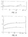
- La figure 4 est un graphique du même type que celui de la figure 3.
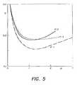
- La figure 5 est un graphique montrant la variaton du coefficient de friction en fonction de l'épaisseur du dépôt et suivant l'état de préparation de surface du substrat avant revêtement.
- Figure 1 is a diagram of a sputtering installation.
- FIG. 2 is a graph showing the relationship between the percentage of sulfur in the compositions, according to the invention, for the deposition of MoS2 and that of said deposits obtained by sputtering.
- FIG. 3 is a graph showing the variation of the friction coefficient of two deposits of MoS2 as a function of the friction time.
- Figure 4 is a graph of the same type as that of Figure 3.
- FIG. 5 is a graph showing the variation of the friction coefficient as a function of the thickness of the deposit and according to the state of surface preparation of the substrate before coating.
On prépare 3 poudres A, B et C destinées à constituer les cibles d'un appareil de pulvérisation cathodique de la manière suivante:
- A: On utilise 20 g de sulfure de molybdène (MERCK, qualité puriss.) dont l'analyse indique qu'elle contient 61,96% de Mo et 38,03% de S, d'autres éléments n'étant pas décelables par les moyens d'analyse utilisés (gravimétrie). En fait, cette composition ne correspond pas exactement à du MOS2 pour (lequel devrait contenir 59,94% de Mo et 40,06% de S), mais plutôt à une sulfure de molybdène contenant un léger excès de métal libre (formule calculée Mo1,089S2).
- B: A un autre lot de 20 g du sulfure de molybdène constituant la composition A ci-dessus, on
ajoute 1,74 g de soufre pour (FLUKA) de manière à porter la concentration en soufre du tout à 43%. - C: On procède de même avec un troisième lot et on
ajoute 4,08 g de S à 20 g du sulfure de molybdène (MERCK) de manière à porter la concentration en soufre à 48,5%.
- A: 20 g of molybdenum sulphide (MERCK, purity quality) are used, the analysis of which indicates that it contains 61.96% of Mo and 38.03% of S, other elements not being detectable by the means of analysis used (gravimetry). In fact, this composition does not exactly correspond to MO S2 for (which should contain 59.94% of Mo and 40.06% of S), but rather to a molybdenum sulphide containing a slight excess of free metal ( calculated formula Mo1.089 S2 ).
- B: To another batch of 20 g of the molybdenum sulphide constituting composition A above, 1.74 g of sulfur is added for (FLUKA) so as to bring the sulfur concentration at all to 43%.
- C: The same procedure is followed with a third batch and 4.08 g of S are added to 20 g of molybdenum sulfide (MERCK) so as to bring the sulfur concentration to 48.5%.
On passe les trois compositions dans un broyeur-mélangeur de façon à réaliser des poudres fines intimement mélangées.The three compositions are passed through a mill-mixer so as to produce intimately mixed fine powders.
Puis on introduit la poudre A dans la cavité d'un disque portecible d'un appareil de pulvérisation cathodique (plaque en AI ou en anti-corrodal de 5 mm d'épaisseur munie d'une creusure circulaire de 60 mm de diamètre et de 2 mm de profondeur). On tasse bien la poudre en la régularisant et, après avoir intercalé une rondelle de papier anti-adhérant, on la soumet à une pression de 0,6×10⁸ Pascal produite par le piston d'une presse hydraulique. Après quelques secondes on obtient ainsi un gâteau homogène et solide de poudre compactée.Then powder A is introduced into the cavity of a target disk of a cathode sputtering device (AI or
Par ailleurs, on sélectionne un certain nombre de plaquettes échantillon s'adaptant au porte-substrat de l'appareil de pulvérisation cathodique. Ces plaquettes, rectangles de 40x20x 1 mm ou disques 17 mm, épaisseur 1,4 mm, sont choisies en cuivre, laiton, bronze, fer, nickel, manifor et sont placées dans ledit portesubstrat de manière à recevoir un dépôt par pulvérisation. Pour la préparation de surface de ces plaquettes, on a utilisé les méthodes suivantes:
- Polissage 1 (P-1): Polissage grossier avec une bande abrasive de 125 pm
- Polissage 2 (P-2): Polissage plus fin avec une pâte de 15 µm
- Polissage 3 (P-3): Polissage fin avec une pâte finale de 0,25 pm.
- Polishing 1 (P-1): Coarse polishing with a 125 µm abrasive strip
- Polishing 2 (P-2): Finer polishing with a 15 µm paste
- Polishing 3 (P-3): Fine polishing with a final paste of 0.25 µm.
Après le polissage les plaquettes ont été décapées mécaniquement, puis dégraissées dans le trichloréthylène chaud (5 min.) puis rincées à l'alcool et séchées.After polishing the wafers were mechanically pickled, then degreased in hot trichlorethylene (5 min.) Then rinsed with alcohol and dried.
L'appareil de pulvérisation cathodique utilisé est représenté schématiquement à la figure 1. Cet appareil comprend une enceinte 1 étanche contenant d'une part un porte-substrat 2 et une cathode 3. Cette cathode comprend, en tant qu'organes essentiels (les seuls représentés ici) un aimant 4, un eplaque porte-cible 5 dans laquelle est ménagée une creusure 6 remplie de la poudre compactée à pulvériser comme on l'a vu plus haut et, pour refroidir le tout, une circulation 7 de liquide réfrigérant, par exemple H20. Le présent appareil est alimenté par deux sources de haute tension, l'une 8 pour la polarisation de la cathode et l'autre 9, pour polariser les substrats pendant le décapage ionique préliminaire.The cathode sputtering apparatus used is shown diagrammatically in FIG. 1. This apparatus comprises a sealed
Finalement, en ce qui concerne l'alimentation en gaz rare d'ionisation, le présent appareil comprend encore une jauge de lecture des pressions 10 et un dispositif auto-régulateur de ladite pression composé d'une jauge de commande 11, pilotant un régulateur électronique 12, celui-ci agissant sur une vanne 13 d'entrée du gaz (par exemple Ar) de manière à maintenir à une valeur constante et prédéterminée la pression de ce gaz pendant la pulvérisation. Par ailleurs, l'appareil comprend encore un conduit d'évacuation 14 relié à la pompe à vide non représentée.Finally, with regard to the supply of rare ionization gas, the present apparatus further comprises a
A titre indicatif, les organes fonctionnels du présent appareil ont été choisis parmi les produits commerciaux suivants:
- Alimentation HT (8): 0 à 2,4 KV, courant jusqu'a 400 mA.
- HV power supply (8): 0 to 2.4 KV, current up to 400 mA.
Alimentation HT (9): Générateur WITTMER 0-2000 V, courant jusqu'à 30 mA, séparée du porte-substrat par 100 kQ.HV power supply (9): WITTMER 0-2000 V generator, current up to 30 mA, separated from the substrate holder by 100 kQ.
Jauge (10): Jauge thermocouples HASTINGS DV6-MGauge (10): HASTINGS DV6-M thermocouple gauge
Jauge (11): PIRANI BALZERS NV4 Régulateur (12): Coffret de contrôle BALZERS RVG2Gauge (11): PIRANI BALZERS NV4 Regulator (12): BALZERS RVG2 control unit
Après avoir disposé les plaquettes sur le porte-substrat 2, on fixe le porte-cible contenant la poudre A pressée sur la cathode 3 et on règle la distance entre celle-ci et le substrat de manière qu'elle corresponde au libre parcours moyen de particules de matériau pulvérisé, c'est-à-dire environ 3 à 6 mm dans les conditions opératoires du présent Exemple. On ferme l'appareil et on y fait le vide (133×10-5―133×10-6 Pascal) avec une pompe à diffusion de type BALZERS PST 900A.After placing the plates on the
Puis, par l'entremise de la vanne 13 on introduit de l'argon à 99,9% provenant d'un cylindre et on règle la pression à 5.10-2 Torr. On polarise le porte-objet et on procède pendant 6 min au décapage ionique des plaquettes de substrat sous un courant de 2mA. Puis, sans arrêter le courant de décapage, on règle la pression d'argon à 266×10-3 Pascal, on enclenche le courant de pulvérisation de manière que les deux effets se superposent, ceci pour éviter une retombée des produits de décapage sur le substrat. Après quelques secondes on coupe le circuit de décapage et on laisse le dépôt se poursuivre sous 7 mA/cm2 de cible, ce qui donne une vitesse de dépôt de 0,1 um/min.Then, through
Lorsqu'on estime qu'il s'est déposé environ 1,5 à 1,8 pm de produit auto-lubrifiant, on arrête l'opération et on retire les plaquettes de l'appareil afin de les soumettre aux analyses et aux tests de friction et on répète la même opération sur d'autres substrats en utilisant successivement comme cibles les compositions B et C.When it is estimated that approximately 1.5 to 1.8 μm of self-lubricating product has deposited, the operation is stopped and the platelets are removed from the apparatus in order to submit them to analyzes and friction and the same operation is repeated on other substrates, successively using compositions B and C as targets.
Puis on recommence le tout avec d'autres plaquettes en laisant la pulvérisation s'effectuer pendant des périodes différentes, de manière à obtenir toute une gamme d'échantillons de matières diverses, recouverts de films de compositions et d'épaisseurs différentes et déposés sur des surfaces de finitions différentes.Then we start all over with other plates, allowing the spraying to take place for different periods, so as to obtain a whole range of samples of various materials, covered with films of different compositions and thicknesses and deposited on surfaces with different finishes.
Les compositions chimiques des dépôts ont été analysées et portées sur un graphique en fonction de celles des poudres correspondantes ayant servi de cible (voir fig. 2). On constate, d'après ce graphique, qu'il existe, dans les conditions opératoires précitées, une relation pratiquement linéaire entre la composition des mélanges de départ et celle des revêtements. On voit aussi qu'a une composition pulvérisable contentant 42,8% de S correspond un dépôt contenant 40,06% de soufre (quantité stoechiométrique correspondant à la formule MoS2).The chemical compositions of the deposits were analyzed and plotted against those of the corresponding powders used as targets (see fig. 2). It can be seen from this graph that, under the above operating conditions, there is a practically linear relationship between the composition of the starting mixtures and that of the coatings. It can also be seen that a sprayable composition containing 42.8% of S corresponds to a deposit containing 40.06% of sulfur (stoichiometric quantity corresponding to the formula MoS2 ).
Les tests de friction auxquels ont été ensuite soumis ces échantillons sont les suivants:
- I. Test de "disque et bille": L'appareil utilisé pour cet essai, dont une forme est décrite dans ASLE
transactions 14, [4], 267-274, comprend un disque support sur lequel on monte l'éhantillon à tester sour forme d'une plaquette de forme circulaire contre laquelle applique une butée à bille dont la pression contre l'échantillon est réglable et qui comporte un jeu de jauges de contrainte permettant de mesurer la force de frottement entre la bille et l'échantillon. Le disque étant mis en rotation à une vitesse déterminée, on note le nombre de tours ou le temps nécessaire pour éroder le dépôt (c'est-à-dire provoquer une augmentation notable de la friction) sous une pression déterminée de la bille. Pour les présents tests "disque et bille" on a utilisé les paramètres suivants:
- I. "Disc and ball" test: The apparatus used for this test, a form of which is described in
ASLE transactions 14, [4], 267-274, includes a support disc on which the sample to be tested is mounted. form of a circular plate against which a ball stop is applied, the pressure against the sample is adjustable and which includes a set of strain gauges for measuring the friction force between the ball and the sample. The disc being rotated at a determined speed, note the number of revolutions or the time necessary to erode the deposit (that is to say cause a significant increase in friction) under a determined pressure of the ball. For the present "disc and ball" tests, the following parameters were used:
Bille 0,7 mm, acier ou rubis synthétique; vitesse de déplacement 1 cm/sec; charge 56 kg/mm2; pression et température ambiante.0.7 mm ball, steel or synthetic ruby;
Il. Pendule de Barker: Ce pendule est constitué d'un balancier métallique rigide muni d'un poids réglable et dont l'organe de pivotement (une rotule sphérique) respose entre deux surfaces planes disposées en V, l'angle de celui-ci étant de 90°. Pour la mesure, on place les revêtements à tester sur les surfaces du V en contact avec la rotule, on déplace le bras du pendule de sa position d'équilibre d'un angle déterminé par une échelle graduée, on le libère afin qu'il entre en balancement et, après un nombre déterminé de périodes, on lit la valeur de l'amplitude du dernier balancement. Le coefficient de friction est lié aux paramètres ci-dessus par la relation suivante:
L'épaisseur des dépôts a été mesurée par interférométrie suivant les moyens habituels et, plus spécialement, par la méthode "TALYSURF". Pour l'application de cette méthode, on utilise un comparateur enregistreur dont le curseur se déplace linéairement sur la surface à étrudier et qui enregistre (en les amplifant foretment) les différences de niveaux rencontrés par ce curseur. Pour pouvoir mesurer l'épaisseur d'un dépôt, on applique préalablement sur le substrat, avant revêtement, un fil métallique qui, une fois le film déposé, laisse après arrachage une trace dont la profondeur correspond à l'épaisseur à mesurer.The thickness of the deposits was measured by interferometry according to the usual means and, more particularly, by the "TALYSURF" method. For the application of this method, a recording comparator is used, the cursor of which moves linearly over the surface to be studied and which records (by amplifying them foretly) the differences in levels encountered by this cursor. In order to be able to measure the thickness of a deposit, a metal wire is applied to the substrate before coating, which, once the film has been deposited, leaves a tear after tearing, the depth of which corresponds to the thickness to be measured.
Les résultats des tests ci-dessus sur les différents échantillons de placage préparés suivant le présent exemple ont permis de mettre en relation les qualités auto-lubrifiantes des dépôts de sulfure de molybdène "turbostra- tiques" avec les variables suivantes: l'état de surface du substrat, l'épaisseur du dépôt et la composition de celui-ci.The results of the above tests on the various plating samples prepared according to the present example made it possible to relate the self-lubricating qualities of the "turbostatic" molybdenum sulfide deposits to the following variables: the surface condition of the substrate, the thickness of the deposit and the composition thereof.
Ainsi à la figure 3, on a porté la variation du coefficient de friction avec le temps suivant le test "disque et bille" d'un revêtement A de 1 µm (obtenu à partir de la composition A ci-dessus) et d'un revêtement C de 1,1 µm (obtenu à partir de la composition C) sur un substrat d'acier finement poli (méthode P-3). On constate que, dans ce test, le revêtement A pauvre en soufre garde ses propriétés auto-lubrifiantes (>6000 h) plus longtemps que le revêtement C riche en soufre (-100 h). On a, par ailleurs, fait subir un traitement comparable à des revêtements d'épaisseur comparable obtenu par les moyens classiques (voir, par exemple les méthodes de dépôt par pulvérisation décrites dans les deux premières références citées dans l'introduction et, également la référence suivante: G. ROCHAT et al., Lubrification solide de mobiles micromécaniques, L.S.R.H. Conférence No F 2.6, CIC Genéve, 1979) et on a constaté que la résistance de tels dépôts à l'usure était considérablement inférieure à celle des dépôts turobstratiques de l'invention. En effet, les revêtements auo-lubrifiants classiques perdaient leurs propriétés après une période de l'ordre de 120 à 150 h seulement.Thus in FIG. 3, the variation of the coefficient of friction has been plotted over time following the "disc and ball" test of a coating A of 1 μm (obtained from composition A above) and of a coating C of 1.1 μm (obtained from composition C) on a finely polished steel substrate (method P-3). It is noted that, in this test, the coating A poor in sulfur retains its self-lubricating properties (> 6000 h) longer than the coating C rich in sulfur (-100 h). Furthermore, a treatment comparable to coatings of comparable thickness obtained by conventional means has been subjected (see, for example the spray deposition methods described in the first two references cited in the introduction and, also the reference following: G. ROCHAT et al., Solid lubrication of micromechanical mobiles, LSRH Conférence No F 2.6, CIC Genéve, 1979) and it was found that the resistance of such deposits to wear was considerably lower than that of turobstratic deposits of l 'invention. Indeed, conventional self-lubricating coatings lost their properties after a period of the order of only 120 to 150 h.
Cependant, pour deux revêtements identiques déposés sur laiton (polissage P-3), on a constaté que la composition C donnait un revêtement plus glissant que la composition A. Cet état de chose est illustré par la figure 4 où on a porté la variation de q en fonction du nombre de cycles dans le test du pendule de Barker (courbe pointillée=résultats obtenus sur le revêtement A; courbe pleine=résultats obtenus sur le revêtement C).However, for two identical coatings deposited on brass (polishing P-3), it was found that composition C gave a more slippery coating than composition A. This state of affairs is illustrated by FIG. 4 where the variation of q as a function of the number of cycles in the Barker pendulum test (dotted curve = results obtained on coating A; solid curve = results obtained on coating C).
Par ailleurs, sur le graphique représenté à la figure 5, on a porté les variations du coefficient de friction (obtenu par les test du pendule de Barker) en fonction de l'épaisseur en µm du dépôt (composition C) sur acier Sandvik 17 AP et ceci pour des substrats polis suivant les méthodes décrites plus haut (P-1=courbe mixte; P-2=courbe pleine et P-3=courbe pointillée). On constate avec surprise que les revêtements les plus glissants sont obtenus sur les substrats les plus rugueux. Par ailleurs, l'epaisseur des dépôts conduisant au minimum est de l'ordre de 1 à 1,5 pm.Furthermore, on the graph represented in FIG. 5, the variations of the friction coefficient (obtained by the Barker pendulum tests) have been plotted as a function of the thickness in μm of the deposit (composition C) on Sandvik 17 AP steel. and this for polished substrates according to the methods described above (P-1 = mixed curve; P-2 = solid curve and P-3 = dotted curve). It is surprising to note that the most slippery coatings are obtained on the roughest substrates. Furthermore, the thickness of the deposits leading to the minimum is of the order of 1 to 1.5 μm.
On a sélectionné un lot de roues d'échappement de mouvements d'horlogerie qu'on a empilées les unes sur les autres en faisant coïncider leur trou central de manière obtenir un bloc cylindrique percé axialement. Par l'entremise de ce trou central, on a monté ce bloc sur l'axe d'un dispositif de mise en rotation, les faces planes du cylindre étant masquée, de part et d'autre, par des bagues de serrage en matière plastique. Le dispositif rotatif, mis en mouvement de l'extérieur par l'entremise d'une transmission à joints étanches a été placé en guise de porte-substrat dans un appareil de pulvérisation cathodique similaire à celui décrit à l'Exemple 1, Le dépôt de matière autolubrifiante étant destiné à recouvrir la partie externe des dents des roues d'échappement (la zone frappée par l'ancre du mouvement) celles-ci ont subi, auparavant, un traitement de polissage fin tel que décrit à l'exemple précedent. Dans certains cas, le polissage mécanique a été remplacé par un polissage électrolytique. Après polissage, les pièces ont été dégraissées et nettoycées comme décrit à l'Exemple 1.We selected a batch of escapement clockwork wheels that we stacked on each other by making their central hole coincide so as to obtain a cylindrical block drilled axially. By means of this central hole, this block has been mounted on the axis of a device for rotating, the flat faces of the cylinder being masked on both sides by plastic clamping rings. . The rotary device, set in motion from the outside by means of a sealed joint transmission, was placed as a substrate holder in a cathode sputtering device similar to that described in Example 1, The deposit of self-lubricating material being intended to cover the external part of the teeth of the escapement wheels (the area struck by the anchor of the movement), these have previously undergone a fine polishing treatment as described in the preceding example. In some cases, mechanical polishing has been replaced by electrolytic polishing. After polishing, the parts were degreased and cleaned as described in Example 1.
Pour les dépôts on a utilisé des cibles de composition semblable à la composition C de l'Exemple 1 donnant des dépôts relativement riches en soufre et à des épaisseurs de 1 à 1,5 pm.For the deposits, targets of composition similar to composition C of Example 1 were used, giving deposits relatively rich in sulfur and with thicknesses of 1 to 1.5 μm.
Les roues une fois revêtues ont été utilisées pour le montage de mouvements d'horlogerie et ces mouvements ont été testés sur un ampliscope GREINER permettent de déterminer l'amplitude des mouvements de l'axe du balancier. La grandeur de cette amplitude est en effet une mesure de la qualité lubrifiante des dents de l'échappement. On a constaté que, dans tous les cas, les propriétés auto-lubrifiantes des revêtements obtenus suivant l'invention étaient supérieures à celles des dépôts similaires obtenus par les moyens habituels, notamment par aspersion des surfaces frottantes par une dispersion de MoS2 dans un solvant volatil ou dépôt par pulvérisation suivant la technique de Spalvins (voir référence citée dans l'introduction).Once coated, the wheels were used to mount clock movements and these movements were tested on a GREINER ampliscope to determine the amplitude of the movements of the balance axis. The magnitude of this amplitude is indeed a measure of the lubricating quality of the teeth of the exhaust. It was found that, in all cases, the self-lubricating properties of the coatings obtained according to the invention were superior to those of similar deposits obtained by the usual means, in particular by spraying the rubbing surfaces with a dispersion of MoS2 in a solvent. volatile or spray deposition according to the Spalvins technique (see reference cited in the introduction).
On notera que les revêtements auto- lubrifiants suivant l'invention sont également utiles sur d'autres pièces de mécanique et notâmment les pièces horlogères en rotation, animées de mouvements d'oscillation ou subissant des efforts de frottement et/ou de percussion, telles que, par exemple, des éléments d'échappement, engrenages, roues, pivots, axes, paliers, cliquets, etc.It will be noted that the self-lubricating coatings according to the invention are also useful on other mechanical parts and in particular horological parts in rotation, driven by oscillating movements or undergoing frictional and / or percussion forces, such as , for example, exhaust elements, gears, wheels, pivots, axes, bearings, pawls, etc.
On a déposé, sous 2 . 10-3 Torr (266x 10-3 Pascal) d'argon et une densité de courant 7 mA/cm2 une série de chalcogénures métalliques dont la liste figure au Tableau ci-dessous. Les produits utilisés étaient des chalcogénures commerciaux qu'on a simplement séchés à l'air sans autre purification. Les tensions cathodiques et les rendements de placage sont également donnés au Tableau. Les propriétés de lubrification des dépôts obtenus (env. 1 pm) sur acier ont été testés au Pendule de Baxter, les coefficients de friction moyens figurent également au Tableau ci-dessous.
Claims (8)
Priority Applications (1)
| Application Number | Priority Date | Filing Date | Title |
|---|---|---|---|
| AT79810117TATE2443T1 (en) | 1978-10-09 | 1979-10-08 | PROCESS FOR DEPOSITIONING A SELF-LUBRICATION COATING OF METALLIC CHALCOGENIDES ONTO SUBSTRATES BY CATHODE SPRAYING. |
Applications Claiming Priority (2)
| Application Number | Priority Date | Filing Date | Title |
|---|---|---|---|
| CH10455/78 | 1978-10-09 | ||
| CH1045578 | 1978-10-09 |
Publications (2)
| Publication Number | Publication Date |
|---|---|
| EP0010070A1 EP0010070A1 (en) | 1980-04-16 |
| EP0010070B1true EP0010070B1 (en) | 1983-02-09 |
Family
ID=4363410
Family Applications (1)
| Application Number | Title | Priority Date | Filing Date |
|---|---|---|---|
| EP79810117AExpiredEP0010070B1 (en) | 1978-10-09 | 1979-10-08 | Cathodic sputtering method for depositing an autolubricant coating of metallic chalcogenides onto substrates |
Country Status (6)
| Country | Link |
|---|---|
| US (1) | US4324803A (en) |
| EP (1) | EP0010070B1 (en) |
| JP (1) | JPS55500784A (en) |
| AT (1) | ATE2443T1 (en) |
| DE (1) | DE2964735D1 (en) |
| WO (1) | WO1980000712A1 (en) |
Families Citing this family (23)
| Publication number | Priority date | Publication date | Assignee | Title |
|---|---|---|---|---|
| US5462772A (en)* | 1957-06-27 | 1995-10-31 | Lemelson; Jerome H. | Methods for forming artificial diamond |
| ATE15698T1 (en)* | 1981-06-30 | 1985-10-15 | Suisse Horlogerie Rech Lab | PROCESS FOR MAKING A CORROSION RESISTANT SOLID LUBRICANT COATING. |
| US4508608A (en)* | 1983-04-21 | 1985-04-02 | Combustion Engineering, Inc. | Method for making chalcogenide cathodes |
| DE3516933A1 (en)* | 1985-05-10 | 1986-11-13 | Deutsche Forschungs- und Versuchsanstalt für Luft- und Raumfahrt e.V., 5300 Bonn | METHOD FOR APPLYING A MOS (DOWN ARROW) 2 (DOWN ARROW) COATING TO A SUBSTRATE |
| US4891112A (en)* | 1985-11-12 | 1990-01-02 | Eastman Kodak Company | Sputtering method for reducing hillocking in aluminum layers formed on substrates |
| FR2638764B1 (en)* | 1988-11-04 | 1993-05-07 | Centre Nat Rech Scient | COMPOSITE ELEMENT COMPRISING A TITANIUM CHALCOGENIDE OR OXYCHALCOGENIDE LAYER, IN PARTICULAR AS A POSITIVE ELECTRODE IN A THIN-LAYER ELECTROCHEMICAL CELL |
| CA2078245A1 (en)* | 1991-09-23 | 1993-03-24 | Roland Dubach | Machining tools |
| FR2697317B1 (en)* | 1992-10-28 | 1995-01-27 | Lyon Ecole Centrale | Lubricated mechanical friction part and lubrication process enabling it to be obtained. |
| US5370778A (en)* | 1992-11-19 | 1994-12-06 | Iowa State University Research Foundation, Inc. | Method for preparing basal oriented molybdenum disulfide (MoS2) thin films |
| US5740941A (en)* | 1993-08-16 | 1998-04-21 | Lemelson; Jerome | Sheet material with coating |
| DE19825572A1 (en)* | 1998-06-08 | 1999-12-09 | Widia Gmbh | Hard metal, cermet, ceramic or steel tool especially a throwaway cutter tip for machining metal |
| GB2360790A (en)* | 2000-03-28 | 2001-10-03 | Gehan Anil Joseph Amaratunga | Low friction coatings produced by cathodic arc evaporation |
| CN1520526A (en) | 2001-04-12 | 2004-08-11 | �ź㴫 | High index-contrast fiber waveguide and applications thereof |
| US8058797B2 (en) | 2001-05-18 | 2011-11-15 | Cambridge University Technical Services Limited | Electroluminescent device |
| US6660136B2 (en)* | 2002-03-27 | 2003-12-09 | Micron Technology, Inc. | Method of forming a non-volatile resistance variable device and method of forming a metal layer comprising silver and tungsten |
| AU2003295929A1 (en)* | 2002-11-22 | 2004-06-18 | Omniguide, Inc. | Dielectric waveguide and method of making the same |
| EP1486582A1 (en)* | 2003-06-13 | 2004-12-15 | Asulab S.A. | Low friction Micromechanical device |
| DE102004015231B4 (en)* | 2004-03-29 | 2015-12-31 | Fraunhofer-Gesellschaft zur Förderung der angewandten Forschung e.V. | Method and device for treating substrate surfaces by means of charge carrier bombardment |
| US20070007505A1 (en)* | 2005-07-07 | 2007-01-11 | Honeywell International Inc. | Chalcogenide PVD components |
| US8901943B1 (en)* | 2008-05-13 | 2014-12-02 | Ronald J. Kita | Gravitational attenuating material |
| EP2438394A4 (en)* | 2009-05-26 | 2017-07-12 | Udo Wolfgang Bucher | Wet paint coating thickness measurement and instrument |
| JP6211754B2 (en)* | 2012-09-28 | 2017-10-11 | セイコーインスツル株式会社 | Manufacturing method of machine part and machine part |
| US20150345010A1 (en)* | 2013-09-30 | 2015-12-03 | University Of Dayton | Methods of magnetically enhanced physical vapor deposition |
Family Cites Families (2)
| Publication number | Priority date | Publication date | Assignee | Title |
|---|---|---|---|---|
| CH431395A (en)* | 1964-08-17 | 1966-09-30 | Ebauches Sa | Self-lubricating friction device between two surfaces |
| US4025410A (en)* | 1975-08-25 | 1977-05-24 | Western Electric Company, Inc. | Sputtering apparatus and methods using a magnetic field |
- 1979
- 1979-10-08EPEP79810117Apatent/EP0010070B1/ennot_activeExpired
- 1979-10-08ATAT79810117Tpatent/ATE2443T1/ennot_activeIP Right Cessation
- 1979-10-08DEDE7979810117Tpatent/DE2964735D1/ennot_activeExpired
- 1979-10-08JPJP50161379Apatent/JPS55500784A/jaactivePending
- 1979-10-08WOPCT/CH1979/000132patent/WO1980000712A1/enunknown
- 1980
- 1980-06-09USUS06/196,483patent/US4324803A/ennot_activeExpired - Lifetime
Also Published As
| Publication number | Publication date |
|---|---|
| US4324803A (en) | 1982-04-13 |
| DE2964735D1 (en) | 1983-03-17 |
| ATE2443T1 (en) | 1983-03-15 |
| EP0010070A1 (en) | 1980-04-16 |
| WO1980000712A1 (en) | 1980-04-17 |
| JPS55500784A (en) | 1980-10-16 |
Similar Documents
| Publication | Publication Date | Title |
|---|---|---|
| EP0010070B1 (en) | Cathodic sputtering method for depositing an autolubricant coating of metallic chalcogenides onto substrates | |
| Gan et al. | Preparation and characterization of copper oxide thin films deposited by filtered cathodic vacuum arc | |
| US6143142A (en) | Composite coatings | |
| Ye et al. | Microstructure and tribological properties of MoS2+ Zr composite coatings in high humidity environment | |
| EP0119459B1 (en) | Part comprising a substrate provided with a hard and corrosion-resistant coating | |
| Aubert et al. | Preparation and properties of MoSx films grown by dc magnetron sputtering | |
| Wang et al. | Effects of HiPIMS pulse-length on plasma discharge and on the properties of WC-DLC coatings | |
| Long et al. | Structural and mechanical properties of amorphous Si–C-based thin films deposited by pulsed magnetron sputtering under different sputtering powers | |
| Mei et al. | Effect of nitrogen partial pressure on microstructure and mechanical properties of Mo-Cu-VN composite coatings deposited by HIPIMS | |
| Konca et al. | Dry sliding behaviour of non-hydrogenated DLC coatings against Al, Cu and Ti in ambient air and argon | |
| EP3592879A1 (en) | Material comprising a thin layer of an alloy comprising titanium and gold and method for obtaining such a material | |
| EP2045352B1 (en) | Method of obtaining a hard surface on the nanometric scale | |
| Azibi et al. | Effects of nitrogen content on the structural, mechanical, and corrosion properties of ZrN thin films grown on AISI 316L by radiofrequency magnetron sputtering | |
| Guo et al. | Effects of bilayer number and thickness ratio on structure and properties of (Cr, N)-DLC/DLC multilayer films | |
| EP0069701A1 (en) | Process for forming a corrosion-resistant coating of a solid lubricant | |
| Zhao et al. | Effect of axial magnetic field on the microstructure, hardness and wear resistance of TiN films deposited by arc ion plating | |
| JPH0625826A (en) | Sliding material and its production | |
| Saoula et al. | Effect of the plasma deposition parameters on the properties of Ti/TiC multilayers for hard coatings applications | |
| Liu et al. | Tailoring the lubricative and electroconductive bifunction properties of NbSe2 film by controlling the sputtering plasma | |
| Lou et al. | Mechanical properties of amorphous carbon nitride films | |
| Klimovich et al. | Influence of Parameters of Reactive Magnetron Sputtering on Tribomechanical Properties of Protective Nanostructured Ti–Al–N Coatings | |
| Zeng et al. | Influence of sulfidation treatment on the structure and tribological properties of nitrogen-doped diamond-like carbon films | |
| Wang et al. | Frictional and wear behavior of micro-crystalline and nano-crystalline diamond films | |
| Medeiros et al. | Amorphous silicon carbide thin films deposited by magnetron co-sputtering: Effect of applied power and deposition pressure on film characteristics | |
| EP0001953A1 (en) | Antifriction alloy, process for the manufacture thereof, and die and lubricant containing such an alloy |
Legal Events
| Date | Code | Title | Description |
|---|---|---|---|
| PUAI | Public reference made under article 153(3) epc to a published international application that has entered the european phase | Free format text:ORIGINAL CODE: 0009012 | |
| AK | Designated contracting states | Designated state(s):AT CH DE FR GB IT NL SE | |
| 17P | Request for examination filed | ||
| ITF | It: translation for a ep patent filed | ||
| GRAA | (expected) grant | Free format text:ORIGINAL CODE: 0009210 | |
| AK | Designated contracting states | Designated state(s):AT CH DE FR GB IT NL SE | |
| REF | Corresponds to: | Ref document number:2443 Country of ref document:AT Date of ref document:19830315 Kind code of ref document:T | |
| REF | Corresponds to: | Ref document number:2964735 Country of ref document:DE Date of ref document:19830317 | |
| PGFP | Annual fee paid to national office [announced via postgrant information from national office to epo] | Ref country code:SE Payment date:19840930 Year of fee payment:6 | |
| PGFP | Annual fee paid to national office [announced via postgrant information from national office to epo] | Ref country code:FR Payment date:19841012 Year of fee payment:6 | |
| PGFP | Annual fee paid to national office [announced via postgrant information from national office to epo] | Ref country code:DE Payment date:19841026 Year of fee payment:6 | |
| PGFP | Annual fee paid to national office [announced via postgrant information from national office to epo] | Ref country code:CH Payment date:19841030 Year of fee payment:6 | |
| PGFP | Annual fee paid to national office [announced via postgrant information from national office to epo] | Ref country code:AT Payment date:19850926 Year of fee payment:7 | |
| PGFP | Annual fee paid to national office [announced via postgrant information from national office to epo] | Ref country code:NL Payment date:19851031 Year of fee payment:7 | |
| PG25 | Lapsed in a contracting state [announced via postgrant information from national office to epo] | Ref country code:AT Effective date:19861008 | |
| PG25 | Lapsed in a contracting state [announced via postgrant information from national office to epo] | Ref country code:SE Effective date:19861009 | |
| PG25 | Lapsed in a contracting state [announced via postgrant information from national office to epo] | Ref country code:CH Effective date:19861031 | |
| PG25 | Lapsed in a contracting state [announced via postgrant information from national office to epo] | Ref country code:NL Effective date:19870501 | |
| NLV4 | Nl: lapsed or anulled due to non-payment of the annual fee | ||
| PG25 | Lapsed in a contracting state [announced via postgrant information from national office to epo] | Ref country code:FR Free format text:LAPSE BECAUSE OF NON-PAYMENT OF DUE FEES Effective date:19870630 | |
| REG | Reference to a national code | Ref country code:CH Ref legal event code:PL | |
| GBPC | Gb: european patent ceased through non-payment of renewal fee | ||
| PG25 | Lapsed in a contracting state [announced via postgrant information from national office to epo] | Ref country code:DE Effective date:19870701 | |
| REG | Reference to a national code | Ref country code:FR Ref legal event code:ST | |
| PG25 | Lapsed in a contracting state [announced via postgrant information from national office to epo] | Ref country code:GB Effective date:19881118 | |
| EUG | Se: european patent has lapsed | Ref document number:79810117.6 Effective date:19870811 | |
| PLBE | No opposition filed within time limit | Free format text:ORIGINAL CODE: 0009261 | |
| STAA | Information on the status of an ep patent application or granted ep patent | Free format text:STATUS: NO OPPOSITION FILED WITHIN TIME LIMIT |