EP0009414B1 - Apparatus and method for controlling windscreen wiper and windscreen washer apparatus of a vehicle - Google Patents
Apparatus and method for controlling windscreen wiper and windscreen washer apparatus of a vehicleDownload PDFInfo
- Publication number
- EP0009414B1 EP0009414B1EP79301984AEP79301984AEP0009414B1EP 0009414 B1EP0009414 B1EP 0009414B1EP 79301984 AEP79301984 AEP 79301984AEP 79301984 AEP79301984 AEP 79301984AEP 0009414 B1EP0009414 B1EP 0009414B1
- Authority
- EP
- European Patent Office
- Prior art keywords
- windscreen
- switch
- control
- infra
- sensor
- Prior art date
- Legal status (The legal status is an assumption and is not a legal conclusion. Google has not performed a legal analysis and makes no representation as to the accuracy of the status listed.)
- Expired
Links
- 238000000034methodMethods0.000titleclaimsdescription7
- 230000005855radiationEffects0.000claimsdescription45
- XLYOFNOQVPJJNP-UHFFFAOYSA-NwaterSubstancesOXLYOFNOQVPJJNP-UHFFFAOYSA-N0.000claimsdescription27
- 239000000428dustSubstances0.000claimsdescription23
- 230000000694effectsEffects0.000claimsdescription14
- 230000008859changeEffects0.000claimsdescription12
- 230000004075alterationEffects0.000claimsdescription9
- 230000008878couplingEffects0.000claimsdescription6
- 238000010168coupling processMethods0.000claimsdescription6
- 238000005859coupling reactionMethods0.000claimsdescription6
- 238000001514detection methodMethods0.000claimsdescription6
- 230000004044responseEffects0.000claimsdescription2
- 238000001914filtrationMethods0.000claims1
- 230000009467reductionEffects0.000claims1
- 239000003990capacitorSubstances0.000description23
- 230000007246mechanismEffects0.000description8
- 230000001105regulatory effectEffects0.000description5
- 230000001276controlling effectEffects0.000description3
- 239000011521glassSubstances0.000description3
- 238000009499grossingMethods0.000description3
- 238000010586diagramMethods0.000description2
- 230000015556catabolic processEffects0.000description1
- 230000003111delayed effectEffects0.000description1
- 229920003023plasticPolymers0.000description1
- 239000004033plasticSubstances0.000description1
- 230000003252repetitive effectEffects0.000description1
- 230000006335response to radiationEffects0.000description1
- 229920006395saturated elastomerPolymers0.000description1
- 230000035945sensitivityEffects0.000description1
- 238000002604ultrasonographyMethods0.000description1
Images


Classifications
- B—PERFORMING OPERATIONS; TRANSPORTING
- B60—VEHICLES IN GENERAL
- B60S—SERVICING, CLEANING, REPAIRING, SUPPORTING, LIFTING, OR MANOEUVRING OF VEHICLES, NOT OTHERWISE PROVIDED FOR
- B60S1/00—Cleaning of vehicles
- B60S1/02—Cleaning windscreens, windows or optical devices
- B60S1/04—Wipers or the like, e.g. scrapers
- B60S1/06—Wipers or the like, e.g. scrapers characterised by the drive
- B60S1/08—Wipers or the like, e.g. scrapers characterised by the drive electrically driven
- B60S1/0818—Wipers or the like, e.g. scrapers characterised by the drive electrically driven including control systems responsive to external conditions, e.g. by detection of moisture, dirt or the like
- B60S1/0822—Wipers or the like, e.g. scrapers characterised by the drive electrically driven including control systems responsive to external conditions, e.g. by detection of moisture, dirt or the like characterized by the arrangement or type of detection means
- B—PERFORMING OPERATIONS; TRANSPORTING
- B60—VEHICLES IN GENERAL
- B60Q—ARRANGEMENT OF SIGNALLING OR LIGHTING DEVICES, THE MOUNTING OR SUPPORTING THEREOF OR CIRCUITS THEREFOR, FOR VEHICLES IN GENERAL
- B60Q1/00—Arrangement of optical signalling or lighting devices, the mounting or supporting thereof or circuits therefor
- B60Q1/02—Arrangement of optical signalling or lighting devices, the mounting or supporting thereof or circuits therefor the devices being primarily intended to illuminate the way ahead or to illuminate other areas of way or environments
- B60Q1/04—Arrangement of optical signalling or lighting devices, the mounting or supporting thereof or circuits therefor the devices being primarily intended to illuminate the way ahead or to illuminate other areas of way or environments the devices being headlights
- B60Q1/14—Arrangement of optical signalling or lighting devices, the mounting or supporting thereof or circuits therefor the devices being primarily intended to illuminate the way ahead or to illuminate other areas of way or environments the devices being headlights having dimming means
- B60Q1/1415—Dimming circuits
- B60Q1/1423—Automatic dimming circuits, i.e. switching between high beam and low beam due to change of ambient light or light level in road traffic
- B—PERFORMING OPERATIONS; TRANSPORTING
- B60—VEHICLES IN GENERAL
- B60S—SERVICING, CLEANING, REPAIRING, SUPPORTING, LIFTING, OR MANOEUVRING OF VEHICLES, NOT OTHERWISE PROVIDED FOR
- B60S1/00—Cleaning of vehicles
- B60S1/02—Cleaning windscreens, windows or optical devices
- B60S1/04—Wipers or the like, e.g. scrapers
- B60S1/06—Wipers or the like, e.g. scrapers characterised by the drive
- B60S1/08—Wipers or the like, e.g. scrapers characterised by the drive electrically driven
- B60S1/0818—Wipers or the like, e.g. scrapers characterised by the drive electrically driven including control systems responsive to external conditions, e.g. by detection of moisture, dirt or the like
- B60S1/0822—Wipers or the like, e.g. scrapers characterised by the drive electrically driven including control systems responsive to external conditions, e.g. by detection of moisture, dirt or the like characterized by the arrangement or type of detection means
- B60S1/0833—Optical rain sensor
- B60S1/0837—Optical rain sensor with a particular arrangement of the optical elements
- B—PERFORMING OPERATIONS; TRANSPORTING
- B60—VEHICLES IN GENERAL
- B60S—SERVICING, CLEANING, REPAIRING, SUPPORTING, LIFTING, OR MANOEUVRING OF VEHICLES, NOT OTHERWISE PROVIDED FOR
- B60S1/00—Cleaning of vehicles
- B60S1/02—Cleaning windscreens, windows or optical devices
- B60S1/04—Wipers or the like, e.g. scrapers
- B60S1/06—Wipers or the like, e.g. scrapers characterised by the drive
- B60S1/08—Wipers or the like, e.g. scrapers characterised by the drive electrically driven
- B60S1/0818—Wipers or the like, e.g. scrapers characterised by the drive electrically driven including control systems responsive to external conditions, e.g. by detection of moisture, dirt or the like
- B60S1/0822—Wipers or the like, e.g. scrapers characterised by the drive electrically driven including control systems responsive to external conditions, e.g. by detection of moisture, dirt or the like characterized by the arrangement or type of detection means
- B60S1/0862—Wipers or the like, e.g. scrapers characterised by the drive electrically driven including control systems responsive to external conditions, e.g. by detection of moisture, dirt or the like characterized by the arrangement or type of detection means including additional sensors
- B60S1/087—Wipers or the like, e.g. scrapers characterised by the drive electrically driven including control systems responsive to external conditions, e.g. by detection of moisture, dirt or the like characterized by the arrangement or type of detection means including additional sensors including an ambient light sensor
- B—PERFORMING OPERATIONS; TRANSPORTING
- B60—VEHICLES IN GENERAL
- B60Q—ARRANGEMENT OF SIGNALLING OR LIGHTING DEVICES, THE MOUNTING OR SUPPORTING THEREOF OR CIRCUITS THEREFOR, FOR VEHICLES IN GENERAL
- B60Q2300/00—Indexing codes for automatically adjustable headlamps or automatically dimmable headlamps
- B60Q2300/30—Indexing codes relating to the vehicle environment
- B60Q2300/31—Atmospheric conditions
- B60Q2300/314—Ambient light
- Y—GENERAL TAGGING OF NEW TECHNOLOGICAL DEVELOPMENTS; GENERAL TAGGING OF CROSS-SECTIONAL TECHNOLOGIES SPANNING OVER SEVERAL SECTIONS OF THE IPC; TECHNICAL SUBJECTS COVERED BY FORMER USPC CROSS-REFERENCE ART COLLECTIONS [XRACs] AND DIGESTS
- Y10—TECHNICAL SUBJECTS COVERED BY FORMER USPC
- Y10S—TECHNICAL SUBJECTS COVERED BY FORMER USPC CROSS-REFERENCE ART COLLECTIONS [XRACs] AND DIGESTS
- Y10S318/00—Electricity: motive power systems
- Y10S318/02—Windshield wiper controls
Definitions
- This inventionrelates to apparatus and method for controlling windscreen wiper and windscreen washer apparatus of a vehicle.
- German Patent Specification No. 2 316 408discloses a vehicle windscreen wiper/wind- screen washer apparatus which includes a control for operating the apparatus automatically by detecting dust or water on the vehicle windscreen and bringing the wiper mechanism into operation when either is detected. If the windscreen is not cleared by the wiper mechanism after a predetermined time, the washer mechanism is operated. The system therefore has the disadvantage that if the windscreen is covered with dust and is not wet, the wiper mechanism will operate for said predetermined time before water is applied to the windscreen by the washer mechanism. A dry dust covered windscreen is likely to be damaged by the wiper mechanism acting before the washer mechanism is actuated and for that reason the mechanism shown in the German Specification No. 2 316 408 is highly undesirable.
- This inventionprovides a control apparatus for a vehicle having a windscreen, windscreen wiper apparatus and windscreen washer apparatus; said control apparatus comprising: emitter means having an emitter device for generating energy and directing the generated energy away therefrom; sensor means having a control sensor device for sensing energy directed thereto from said emitter device; switch means for coupling to said windscreen wiper apparatus for effecting operation of said windscreen wiper apparatus and of said windscreen washer apparatus; support means supporting said emitter device and control sensor device for mounting these against the interior surface of said windscreen so that, when energy is directed away from said emitter device, a portion of said energy may be reflected back to said control sensor device; and switch control means coupled to said sensor means and to said switch means and being responsive to control the switch means for effecting said operation of said windscreen wiper apparatus; characterised in that said switch means comprises first switch means and second switch means for respective coupling to said windscreen wiper apparatus and to said windscreen washer apparatus, respectively, for effecting operation of said windscreen wiper apparatus pursuant to a change of state of said first
- the inventionalso provides a method of controlling windscreen wiper apparatus and vehicle windscreen washer apparatus comprising detecting the presence of dust or water on a vehicle windscreen by directing energy from the interior of the vehicle through the interior surface of the windscreen to be reflected at the outer surface of the windscreen and to pass back through the windscreen and through the interior surface of the windscreen to the interior of the vehicle, detecting variations in intensity of such reflected energy due to presence of water or dust on the windscreen, and, in response to detection of such variations operating the windscreen wiper apparatus and the windscreen washer apparatus; characterised by operating the windscreen wiper apparatus alone when there is water on the windscreen, and operating both the windscreen wiper apparatus and the windscreen washer apparatus when there is dust on the windscreen.
- a control apparatus 10is shown schematically in Figure 1. It is designed to be fitted to a vehicle so as to control operation of a motor 12 which operates the windscreen wiper apparatus of the vehicle for clearing the windscreen when water or dust is detected on the outer surface of the windscreen. Further, the apparatus 10 is arranged to control operation of a washer pump 14 which is arranged to direct water onto the windscreen during clearing of dust from the windscreen. Further, the apparatus 10 is designed to control the exterior lights 16 of the vehicle, such as the headlights and tail-lights, so as to turn these on under conditions where the ambient light level exterior to the vehicle drops below a first predetermined level and to turn them off when the ambient light level rises to a second predetermined light level.
- the apparatus 10is designed for operation from a vehicle battery 18 having its negative terminal connected to ground and its positive terminal connected via a main control switch S1 to a voltage regulator 24.
- Regulator 24is connected to an infra-red emitter device 26 and thence through a transistor switch 28 to ground.
- An oscillator 31is provided which generates thirty-microsecond pulses at about three millisecond intervals and applies these to the switch 28 so as to turn the switch, on to cause corresponding current pulses of the order of 1 ampere to flow from the voltage regulator through the emitter device 26 and switch 28 to ground.
- the emitter deviceis caused to generate infra-red radiation.
- device 26is in use positioned against the interior face 30a of the vehicle windscreen 30 so as to direct radiation on paths 34 from the device 26 through the rear face 30a into the windscreen and to the front face 30b.
- the angle of the paths 34is arranged to be in the range 20 to 40° to the normal 36 to the windscreen as indicated. Then, a portion of the rays striking the outer face 30b of the windscreen are reflected back towards the rear face 30a on paths 38 as indicated whilst most of the radiation passes directly through the windscreen to leave the windscreen forwardly thereof on the paths 40 indicated.
- the presence of water droplets on the outer face 30bis such as to alter the proportion of radiation passing back on the reflected paths 38.
- radiationis lost through scattering and through the random reflections at the outer face 30b.
- the apparatus 10further includes sensor means 51 including an infra-red sensor 43 and a detector 44 referred to in greater detail later.
- the sensor 43as shown in Figure 5 is positioned against the rear face 30a of windscreen 30 so as to normally receive the reflected rays on path 38 from emitter device 26. However, as illustrated in Figure 6, under the condition where water droplets are present on outer face 30b, the amount of radiation reaching the sensor 43 is lessened.
- the emitter device 26 and sensor 43are mounted by a specific structure on the windscreen, such structure being illustrated in Figures 2 and 3 and described in detail later. It will, however, for the moment, be noted that in addition to the sensor 43 carried by such structure, there is also a further sensor 45 which is so shielded as not to receive reflected radiation at all, but to receive direct radiation from device 26. Sensor 45 acts as a reference sensor also in a manner as described later.
- the sensor 43is connected to a detector 44 forming part of sensor means 51 such that the output from the detector comprises a pulsed voltage, the amplitude of pulses thereof being substantially directly proportional to the amount of radiation received by the sensor 43 so that under the condition where water droplets 42 are present there will be a decrease in pulse signal amplitude from the detector 44 and under the condition when there is dust on the windscreen, there will be an increase in signal amplitude.
- the pulse signals from detector 44are applied to a smoothing filter 48 to produce a dc voltage the magnitude of which is proportional to the amount of reflected radiation striking the sensor 43.
- Sensor 45is also connected to a detector 46 which generates pulsed signals of amplitude which is constant for a given temperature.
- the outputs from the sensors 43, 45 in response to radiation from the emitter 26will vary with temperature and so the amplitude of pulses from both the detectors 46 and 44 will vary with temperature.
- the pulses from detector 46are filtered in a filter 50 to generate a dc reference voltage which varies only in accordance with temperature.
- the outputs from filters 48, 50are applied to a comparator 60 forming part of a switch control means 53. Under the normal condition where the outer surface 30b of windscreen 30 is dry and clean, the output from filter 48 is just above the reference voltage comprising the output from filter 50.
- An additional comparator 64receives the outputs from filters 48 and 50. This is arranged to receive the outputs in relatively reversed relationship compared to comparators 52, 60 so that the output signal therefrom is generated when output from filter 48 exceeds that from filter 50, to then operate yet another transistor switch 66 which controls operation of a washer pump 14.
- comparator 64when dust is on the outer surface of the windscreen, output from filter 48 rises and comparator 64 is operated to cause washer pump 14 to operate and apply water to the outer surface of the windscreen.
- the switch 54is also operated by signal applied from the comparator 64 via a diode D1 5 and resistor R37 to operate the windscreen wipers at a fast rate.
- a further detector 49is also coupled to sensor 43. This is arranged to be insensitive to the pulsating signal generated by sensor 43 pursuant to reception by the sensor of infra-red radiation pulses from the emitter device 26.
- sensor 43in addition to receiving pulses of infra-red radiation from emitter device 26, also receives ambient infra-red radiation, and detector 49 is arranged to detect variations in the condition of sensor 43 brought about by such variations in ambient light.
- Detector 49is arranged to operate an additional transistor switch 67 when the condition of sensor 43 is indicative of a low ambient light level.
- Switch 67is arranged to control current supplied to a relay RL3 having relay contacts RL3/1 which control the vehicle lights 16.
- emitter device 26including 3 infra-red emitter devices D1, D2, D3.
- the devices D1, D2, D3are mounted on a mounting assembly 84 connectible to the windscreen 30 of the device.
- Assembly 84includes a plastics box 86 having a front aperture 86A which is covered by a plate 88 carrying the three devices D1, D2, D3 such that emission areas on the surfaces of these are, when the box is positioned against a windscreen 30, positioned immediately behind the rear surface 30a of the windscreen for direction of infra-red radiation from the three devices to the sensor 43.
- the three devices D1, D2, D3are arrayed at equispaced angles about a central location at which location sensor 43 is positioned to stop thus, sensor 43 is positioned in a cylindrical shield located on the front surface of the plate 88 so as to limit incident light reaching the sensor, but such that' the sensor can receive reflected infra-red radiation from the three devices D1, D2, D3.
- the three devices D1, D2, D3are arranged for directing the radiation therefrom at the previously mentioned angle of somewhere between 20 and 40° to the normal to the glass windscreen 30. This presupposes the windscreen glass thickness of about 6 mm and the angle will vary somewhat in dependence upon the glass thickness.
- Plate 88also mounts the sensor 45, which is positioned behind plate 88 so as in use to receive direct radiation from the devices D1, D2, D3.
- Regulator 24includes a transistor Q1 having its collector connected via resistor R1 to switch S1 and its emitter connected via resistor R3 to the three devices D1, D2, D3 which comprise emitter device 26 and which are connected in series as shown.
- a Zener diode D zis connected to the base of transistor Q1 and a resistor R2 is connected between the collector and the base of transistor Q1 so that, when switch S1 is closed, the base of the transistor is held at a voltage of 10 volts as provided by the Zener diode D Z .
- a 10- volt regulated supply for other parts of the electric circuitis taken from the base of transistor Q1, a smoothing capacitor C2 being connected thereto.
- a 9-volt regulated supply for other parts of the circuitis taken from the emitter of transistor Q1, two capacitors C4. C5 being connected to this point for smoothing purposes.
- a 12-volt supply for other parts of the circuitis taken from the junction between resistor R1 and the collector of transistor 01 so that the resistor R1 and capacitor C1 form a filter to filter out noise in the supply path from battery 18.
- a 12-volt supply to operate relays RL1, RL2, RL3is taken directly from the switch S1 at the junction thereof with resistor R1.
- a light emitting diode 80is connected via a resistor 82 to the junction to indicate when switch S1 is turned on.
- Oscillator 31in the form of a pulse generator of conventional form including an operational amplifier having its inverting input coupled to ground via a resistor R16 and parallel capacitor C8 and its non-inverting input connected to ground via a resistor R18.
- the inverting inputis also connected to the output of the operational amplifier via a series resistor R 15 and diode D8.
- the non-inverting inputalso receives the aforementioned 10-volt regulated supply via a resistor R19.
- the non-inverting input of the amplifier 90is also connected to the output via resistor R17. Output from the amplifier 90 is connected via resistor R7 to the switch 28 for controlling the switch.
- Switch 28comprises two transistors Q2, Q3 connected to form a controllable current sink. That is to say, the collectors of both transistors are connected to emitter device 26, whilst the emitter of transistor Q2 is connected to ground via a resistor R4. The emitter of transistor Q3 is connected to the base of transistor Q2 and the base of transistor Q3 is connected to the output of resistor R7. Operation of oscillator 31 causes repetitive switching on of transistor Q2 for the aforementioned 3-millisecond periods, switching on occurring at each instance for some 30-microseconds to cause pulsed infra-red radiation to be emitted from the devices D1, D2, D3 making up emitter device 26.
- Sensor 43comprises a passive device whose resistance varies in dependence with the amount of infra-red radiation incident thereon.
- Sensor 43is connected to the 9-volt regulated supply from regulator 24 and also is connected to ground yia a resistor R5.
- the junction between resistor R5 and sensor 43is connected via a capacitor C6 to the non-inverting input of an operational amplifier 92 forming part of detector device 44.
- a diode D5is connected, via a resistor R10, across resistor R5, whilst the non-inverting input to amplifier 92 is connected to ground via a resistor R11.
- the inverting input of amplifier 92is connected to ground via a resistor R8 and to the output of amplifier 92 via a resistor R9.
- amplifier 92operates to amplify only voltage pulses occurring across resistor R5 pursuant to receipt of light pulses by sensor 43 and produces an output comprising pulses of amplitude proportional to the light pulse strength and independent of the level of ambient light.
- the networkcomprising a series diode D5 and a resistor R10 connected across resistor R5 operates to shunt resistor R5 when the voltage thereacross exceeds a particular level established by the forward breakdown voltage of the diode D5. This shunting slightly lowers the effective resistance between sensor 43 and the ground but to compensate for a slight nonlinear increase in pulse amplitude which would otherwise occur at high ambient light level conditions sensed by sensor 43.
- the sensor 43receives both ambient light through windscreen 30 and pulses of light from emitter device 26, the resistance of sensor 43 exhibits a relatively high frequency variation due to receipt of light pulses from the emitter device and a relatively low frequency variation due to ambient light level variation.
- the junction between resistor R5 and sensor 43will exhibit a voltage having a generally dc component established by the ambient light level as well as a pulsating component the amplitude of which is representative of the amount of radiation being received from each pulse of radiation from the emitter device 26.
- the generally dc voltage componentis blocked from being passed to amplifier 92 by capacitor C6.
- the value of capacitor C6is however chosen to permit the pulsating component to be passed to amplifier 92 as described.
- Filter 48is connected to the output of the operational amplifier 92 via a diode D9.
- the filterincludes:
- Filter 48simply filters amplified pulses from amplifier 92 and produces a dc output proportional to the pulse amplitude.
- Reference signal generator 47including
- a reference signal generator 47has a sensor and a detector 46.
- the sensor 45is connected to the 9-volt regulated supply from regulator 24 and also to ground, via a series network comprising a resistor R6 connected at one end to ground and a variable resistor VR connected between sensor 45 and the other end of resistor R6.
- the junction between sensor 45 and variable resistor VR1is connected via a capacitor C7 to the non-inverting input of an operational amplifier 96 forming part of the detector 46. This input is also connected to ground via a resistor R14.
- the inverting input of amplifier 96is connected to ground via a resistor R12 and is also connected to the amplifier output via a resistor R13.
- sensor 45receives infra-red radiation substantially only from emitter device 26
- the output pulses from the sensor 45will vary in accordance with the pulses of light received from the emitter device and in accordance with ambient temperature variations.
- Operational amplifier 96operates to amplify pulsating variations in voltage appearing across variable resistor VR1 and resistor R6 pursuant to variations in resistance of sensor 45.
- Capacitor C7blocks any dc signal component appearing at the junction between sensor 45 and the network comprising variable resistor VR1 and resistor R6.
- Variable resistor VR1is adjusted so that the output voltage of amplifier 96, as applied through the filter 50 is set to a predetermined level such as to provide effective temperature compensation for the output of sensor 43, as amplified and filtered by detector 44 and filter 48.
- Filter 50is similar to filter 48, being connected to the output of operational amplifier 96 via a diode D10.
- the filterincludes:
- filter 50filters the pulsed output from operational amplifier 96 to provide a smoothed dc reference signal at the output end thereof.
- Comparator 60includes an operational amplifier 100, the inverting input receiving the output from filter 48 and the non-inverting output receiving the output from filter 50.
- the reference signal as applied to the non-inverting input of amplifier 100is adjusted to be just below the signal voltage applied to the inverting input under the condition where windscreen 30 is clean and has no water thereon.
- the comparator outputis switched on as the signal voltage at the inverting input falls, and output is passed, via resistor R35 and two series connected diodes D12, D13, to transistor switch 62.
- Switch 62comprises a transistor Q4 having its base connected to the diode D13, its collector connected to 12-volt supply via a light emitting diode 102 and a series resistor R40, and its emitter connected to ground. Output from the collector of this transistor is applied to one end of the coil of relay RL1, the other end of which relay coil is connected to positive supply. Under the condition when comparator 60 is switched on pursuant to detection of water on the windscreen, positive output is applied to the base of transistor Q4 to turn it on.
- Relay RL1is thus energized so that the contacts RL1 thereof are shifted from the condition shown at which they provide no current path to motor 12 to one at which they provide connection between a "slow" terminal 12a of motor 12 and one terminal of the contacts RL2/1, being a contact terminal which in the unactuated condition of relay contacts RL2/1, is grounded via contacts RL2/1, thus the switching of contacts RL1/1 caused by operation of switch 62 will, unless contacts RL2/1 are also operated, effect completion of a circuit between the "slow" motor terminal and ground via the two relay contacts RL1/1, RL2/1.
- a common terminal of motor 12is connected to positive supply and, on the aforementioned grounding of the slow terminal, the motor operates at slow speed to effect operation of the windscreen wipers at a correspondingly slow rate.
- Comparator 52comprises an operational amplifier 104 having its inverting input connected to the output from filter 48 and its non-inverting input connected to the output of filter 50 via a resistor R26.
- the non-inverting amplifier inputis also connected to ground via a resistor R27 so that the reference voltage derived from filter 50 has a proportion thereof (determined by the ratio of resistors R26, R27) applied to the non-inverting input amplifier 104.
- This proportional voltageis arranged to be such that the amplifier 104 will be turned from a condition at which its output is ground (0 volts) to one at which its output is positive at a relatively lower value of output signal from filter 48 than that required to turn on amplifier 100.
- Switch 54comprises a transistor Q5 having its collector connected to positive supply via a light emitting diode 106 and a series connected resistor R41.
- the transistor emitteris connected to ground and the transistor base is connected to the output of amplifier 104 via a resistor R36.
- the collector of transistor Q5is connected to one end of the coil of relay RL2, the other end of the relay coil thereof connected to positive supply so that when amplifier 104 turns on transistor Q5 is also turned on to ground the collector thereof and connect the relay coil of relay RL2 across supply to energize this and cause switching of relay contacts RL2/1 from the condition shown in the drawing to a condition at which it disconnects connection to the contacts of relay RL1/1 and connects a "fast" terminal of motor 12 directly to ground. Under this condition, motor 12 thus operates at a faster speed to cause consequent faster operation of the wiper blades.
- a diode D14is connected between the collector of transistor Q5 and the junction of resistor R35 and diode D12 so that when the collector of transistor Q5 is grounded, output from amplifier 100 is inhibited to thereby cause switching off of transistor Q4 and reversion of contacts RL1/1 to the condition shown in Figure 1.
- Comparator 64includes an operational amplifier 108 having its inverting input connected to the output from filter 50 and its non-inverting input connected to the output of filter 48 via two series connected resistors R28, R29.
- the junction between resistors R28 and R29is connected to ground via a resistor R30 and the junction between resistor R29 and the non-inverting input of amplifier 108 is connected to ground via a capacitor C13.
- Resistors R28, R30form a divider network which establishes the sensitivity of amplifier 108 whilst resistor R29 and capacitor C13 form a filter network which inhibits switching of amplifier 108 when momentary increases in reflected light back to sensor 43 occur, such as when the wiper blades of the wipers of the vehicle are momentarily over the sensor 43.
- Amplifier 108is so arranged that when the signal level on the non-inverting terminal rises to a predetermined level above the reference voltage as applied from filter 50, the output of the amplifier is turned on. This condition is arranged to be reached when a predetermined level of reflected light is received back from diodes D1, D2, D3 at sensor 43 such as is indicative of the presence of dust on the vehicle windscreen.
- Switch 66includes two transistors Q6, Q7, having their collectors connected to positive supply via a series connected light emitting diode 112 and a resistor R42.
- the base of transistor Q6is connected to the output from amplifier 108 via a resistor R38 whilst the emitter of the transistor Q6 is connected to the base of transistor Q7.
- the emitter of transistor Q7is connected to ground.
- Output at the collector of the transistor Q7is applied via a diode D16 to one terminal of the washer pump 14, the other terminal of the washer pump being connected to positive supply.
- transistor Q7when amplifer 108 turns on, transistor Q7 is likewise turned on to ground the collector thereof so that current can flow from the positive supply via the pump 14 and diode D16 through transistor Q7 to ground to turn on the washer pump and cause water to be directed onto the windscreen. Since it is not sufficient to merely direct water onto the windscreen to ensure dust removal, provision is made for also turning on the wiper motor under the condition of detection of dust for operating the wipers to assist in the removal of the dust.
- the output from amplifier 108is connected via a series network comprising a diode D15 and a resistor R37 to the base of transistor Q5.
- Detector 49includes a first operational amplifier 114 having its non-inverting input connected to the junction between resistor R5 and sensor 43.
- the inverting amplifier inputis connected to ground via a resistor R24 and to the output of the operational amplifier via a resistor R25.
- Output from amplifier 114is connected to the inverting input of the second operational amplifier 116 via a resistor R31 connected in parallel with a diode D11.
- the inverting input of amplifier 116is also connected to ground via a capacitor C14.
- the non-inverting input of amplifier 116is connected to +10 volts reference supply via a resistor R32 and to ground via a resistor R33.
- amplifier 116The non-inverting input of amplifier 116 is also connected to the output of amplifier 116 via a resistor R34.
- Amplifier 114constitutes a direct current amplifier which amplifies a signal voltage from sensor 43 representative of the ambient light level sensed by sensor 43.
- the non pulsating component of voltage across resistor R5(which component is directly proportional to the ambient light level sensed by sensor 43) is more effective for signal levels required to operate detector 49 than the short duration pulsating voltage components, so that the detector 49 can operate on the signal voltage across resistor R5 as if there were no pulsating component of such voltage.
- the operation of detector 49is as follows, bearing in mind that the amplified voltage from amplifier 114 rises under the condition where there is low ambient light detected by sensor 43, and this voltage rise is delayed by the network comprising capacitor C14 and resistor R31.
- the voltage applied to the non-inverting terminal of amplifier 114is such that the amplifier 114 is saturated and capacitor C14 charges through resistor R31 to maintain amplifier 116 turned off.
- the voltage applied to the non-inverting input of amplifier 114is such as to cause the output of amplifier 114 to fall to ground and capacitor C14 immediately discharges via diode D11 to cause variation in the voltage applied to the inverting terminal of amplifier 116 and to cause turning on of this amplifier and also turning on of switch 67.
- turn-on of switch 67occurs virtually immediately on detection of decrease in ambient light levels.
- the network R32, R33 and R34is so arranged such that it requires, under the condition of ambient light increase, twice as high a light level as sensed by sensor 43 before switching off of the output from amplifier 116 will occur as compared to the light level which is required, under the condition of falling ambient light level in order to effect turning on of amplifier 116.
- Switch 67comprises a transistor Q8 having its base connected to the output of amplifier 116 via a resistor R39.
- the emitter of transistor Q8is connected to ground, and the collector is connected to positive supply via a light emitting diode 118 and series resistor R43.
- transistor Q8Under the condition where amplifier 116 is turned on, transistor Q8 is also turned on to cause grounding of the collector thereof which collector is connected to one end of the coil of relay RL3, the other end of the relay coil being connected to positive supply.
- This energization of relay RL3which occurs pursuant to such switching on of transistor Q8 causes closing of contacts RL3/1 so-that the 'lights of the vehicle 16 are turned on by virtue of being connected across positive supply.
- the vehicle lightswill be switched on under the condition where ambient light falls to a first predetermined level and will be switched off when the ambient light again rises to. a second predetermined level, with the switching off occurring only after a 3 second delay following the rise in the ambient light above the second predetermined level.
Landscapes
- Engineering & Computer Science (AREA)
- Mechanical Engineering (AREA)
- Automation & Control Theory (AREA)
- Investigating Or Analysing Materials By Optical Means (AREA)
Description
- This invention relates to apparatus and method for controlling windscreen wiper and windscreen washer apparatus of a vehicle.
- German Patent Specification No. 2 316 408 discloses a vehicle windscreen wiper/wind- screen washer apparatus which includes a control for operating the apparatus automatically by detecting dust or water on the vehicle windscreen and bringing the wiper mechanism into operation when either is detected. If the windscreen is not cleared by the wiper mechanism after a predetermined time, the washer mechanism is operated. The system therefore has the disadvantage that if the windscreen is covered with dust and is not wet, the wiper mechanism will operate for said predetermined time before water is applied to the windscreen by the washer mechanism. A dry dust covered windscreen is likely to be damaged by the wiper mechanism acting before the washer mechanism is actuated and for that reason the mechanism shown in the German Specification No. 2 316 408 is highly undesirable.
- This invention provides a control apparatus for a vehicle having a windscreen, windscreen wiper apparatus and windscreen washer apparatus; said control apparatus comprising: emitter means having an emitter device for generating energy and directing the generated energy away therefrom; sensor means having a control sensor device for sensing energy directed thereto from said emitter device; switch means for coupling to said windscreen wiper apparatus for effecting operation of said windscreen wiper apparatus and of said windscreen washer apparatus; support means supporting said emitter device and control sensor device for mounting these against the interior surface of said windscreen so that, when energy is directed away from said emitter device, a portion of said energy may be reflected back to said control sensor device; and switch control means coupled to said sensor means and to said switch means and being responsive to control the switch means for effecting said operation of said windscreen wiper apparatus; characterised in that said switch means comprises first switch means and second switch means for respective coupling to said windscreen wiper apparatus and to said windscreen washer apparatus, respectively, for effecting operation of said windscreen wiper apparatus pursuant to a change of state of said first switch means and for effecting operation of said windscreen washer apparatus pursuant to a change of state of said second switch means; said sensor means being responsive to the magnitude of said portion of said energy reflected back to said control sensor device to cause a first alteration of electrical condition of the sensor means when there is water on an outer surface of said windscreen opposite said interior surface and to cause a second alteration of said electrical condition when there is dust on said outer surface; and said switch control means being responsive to effect said change of state of said first switch means pursuant to occurrence of said first alteration of electrical condition of said sensor means, for effecting said operation of said windscreen wiper apparatus, and responsive to effect said changes of state of both said first switch means and said second switch means pursuant to occurrence of said second alteration of said electrical condition of said sensor means, for effecting said operations of both said windscreen wiper apparatus and said windscreen washer apparatus.
- The invention also provides a method of controlling windscreen wiper apparatus and vehicle windscreen washer apparatus comprising detecting the presence of dust or water on a vehicle windscreen by directing energy from the interior of the vehicle through the interior surface of the windscreen to be reflected at the outer surface of the windscreen and to pass back through the windscreen and through the interior surface of the windscreen to the interior of the vehicle, detecting variations in intensity of such reflected energy due to presence of water or dust on the windscreen, and, in response to detection of such variations operating the windscreen wiper apparatus and the windscreen washer apparatus; characterised by operating the windscreen wiper apparatus alone when there is water on the windscreen, and operating both the windscreen wiper apparatus and the windscreen washer apparatus when there is dust on the windscreen.
- The invention is described further by way of example only with reference to the accompanying drawings in which:
- Figure 1 is a block diagram of an apparatus constructed in accordance with the invention;
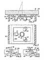
- Figure 2 is a fragmentary cross-section of a windscreen mounting unit forming part of the apparatus of Figure 1;
- Figure 3 is a plan view of the mounting unit of Figure 2;
- Figure 4 is a circuit diagram of the apparatus of Figure 1, and
- Figures 5 and 6 are fragmentary cross-sections of a vehicle windscreen showing paths of infra-red radiation emitted by an infra-red emission means forming part of the apparatus of Figure 1 under conditions where the outer surface of the windscreen is clear and where water droplets are on the outer surface of the windscreen, respectively.
- A
control apparatus 10 is shown schematically in Figure 1. It is designed to be fitted to a vehicle so as to control operation of amotor 12 which operates the windscreen wiper apparatus of the vehicle for clearing the windscreen when water or dust is detected on the outer surface of the windscreen. Further, theapparatus 10 is arranged to control operation of awasher pump 14 which is arranged to direct water onto the windscreen during clearing of dust from the windscreen. Further, theapparatus 10 is designed to control theexterior lights 16 of the vehicle, such as the headlights and tail-lights, so as to turn these on under conditions where the ambient light level exterior to the vehicle drops below a first predetermined level and to turn them off when the ambient light level rises to a second predetermined light level. - The
apparatus 10 is designed for operation from avehicle battery 18 having its negative terminal connected to ground and its positive terminal connected via a main control switch S1 to avoltage regulator 24.Regulator 24 is connected to an infra-red emitter device 26 and thence through atransistor switch 28 to ground. Anoscillator 31 is provided which generates thirty-microsecond pulses at about three millisecond intervals and applies these to theswitch 28 so as to turn the switch, on to cause corresponding current pulses of the order of 1 ampere to flow from the voltage regulator through theemitter device 26 and switch 28 to ground. By this means the emitter device is caused to generate infra-red radiation. - As shown in Figure 5, and described in more detail later,
device 26 is in use positioned against theinterior face 30a of thevehicle windscreen 30 so as to direct radiation onpaths 34 from thedevice 26 through therear face 30a into the windscreen and to thefront face 30b. The angle of thepaths 34 is arranged to be in the range 20 to 40° to the normal 36 to the windscreen as indicated. Then, a portion of the rays striking theouter face 30b of the windscreen are reflected back towards therear face 30a onpaths 38 as indicated whilst most of the radiation passes directly through the windscreen to leave the windscreen forwardly thereof on thepaths 40 indicated. As best shown in Figure 6, the presence of water droplets on theouter face 30b, such as the droplets indicated byreference numeral 42, is such as to alter the proportion of radiation passing back on thereflected paths 38. In particular, radiation is lost through scattering and through the random reflections at theouter face 30b. - The
apparatus 10 further includes sensor means 51 including an infra-red sensor 43 and adetector 44 referred to in greater detail later. Thesensor 43, as shown in Figure 5 is positioned against therear face 30a ofwindscreen 30 so as to normally receive the reflected rays onpath 38 fromemitter device 26. However, as illustrated in Figure 6, under the condition where water droplets are present onouter face 30b, the amount of radiation reaching thesensor 43 is lessened. - Although not shown, there is a further condition under which the amount of radiation reaching the
sensor 43 fromemitter device 26 will vary from the usual condition. That is when there is a layer of dust or the like on theouter face 30b of the windscreen. In this case, there will be a greater amount of reflection alongpaths 38 and less radiation will escape alongpaths 40. In this case, then,sensor 43 receives increased radiation fromemitter device 26. - The
emitter device 26 andsensor 43 are mounted by a specific structure on the windscreen, such structure being illustrated in Figures 2 and 3 and described in detail later. It will, however, for the moment, be noted that in addition to thesensor 43 carried by such structure, there is also afurther sensor 45 which is so shielded as not to receive reflected radiation at all, but to receive direct radiation fromdevice 26.Sensor 45 acts as a reference sensor also in a manner as described later. - Reverting to Figure 1, the
sensor 43 is connected to adetector 44 forming part of sensor means 51 such that the output from the detector comprises a pulsed voltage, the amplitude of pulses thereof being substantially directly proportional to the amount of radiation received by thesensor 43 so that under the condition wherewater droplets 42 are present there will be a decrease in pulse signal amplitude from thedetector 44 and under the condition when there is dust on the windscreen, there will be an increase in signal amplitude. The pulse signals fromdetector 44 are applied to asmoothing filter 48 to produce a dc voltage the magnitude of which is proportional to the amount of reflected radiation striking thesensor 43. Sensor 45 is also connected to adetector 46 which generates pulsed signals of amplitude which is constant for a given temperature. The outputs from thesensors emitter 26 will vary with temperature and so the amplitude of pulses from both thedetectors detector 46 are filtered in afilter 50 to generate a dc reference voltage which varies only in accordance with temperature. The outputs fromfilters comparator 60 forming part of a switch control means 53. Under the normal condition where theouter surface 30b ofwindscreen 30 is dry and clean, the output fromfilter 48 is just above the reference voltage comprising the output fromfilter 50. Under the condition where light rain has fallen on thewindscreen 30, output fromfilter 48 will fall and, when this wall reaches a first magnitude, thecomparator 60 will operate to generate a signal which is applied to atransistor switch 62 which controls current supply to a relay RL1 so that the contacts RL1/1 of relay RL1 are operated to operate themotor 12 at a slow rate. Anothercomparator 52 forming part of said switch control means 53 also receives outputs from the twofilters filter 48 exceeds a second magnitude greater than the first magnitude required to operatecomparator 60, anothertransistor switch 54 is operated to operate a further relay RL2 the contacts RL2/1 of which are then operated to operatemotor 12 at a fast speed.- An
additional comparator 64 receives the outputs fromfilters comparators filter 48 exceeds that fromfilter 50, to then operate yet anothertransistor switch 66 which controls operation of awasher pump 14. Thus, when dust is on the outer surface of the windscreen, output fromfilter 48 rises andcomparator 64 is operated to causewasher pump 14 to operate and apply water to the outer surface of the windscreen. When this occurs, theswitch 54 is also operated by signal applied from thecomparator 64 via adiode D1 5 and resistor R37 to operate the windscreen wipers at a fast rate. - A
further detector 49 is also coupled tosensor 43. This is arranged to be insensitive to the pulsating signal generated bysensor 43 pursuant to reception by the sensor of infra-red radiation pulses from theemitter device 26. However, it will be appreciated thatsensor 43, in addition to receiving pulses of infra-red radiation fromemitter device 26, also receives ambient infra-red radiation, anddetector 49 is arranged to detect variations in the condition ofsensor 43 brought about by such variations in ambient light. Detector 49 is arranged to operate anadditional transistor switch 67 when the condition ofsensor 43 is indicative of a low ambient light level.Switch 67 is arranged to control current supplied to a relay RL3 having relay contacts RL3/1 which control thevehicle lights 16.- The physical arrangement of the
emitter device 26 andsensors emitter device 26 is shown including 3 infra-red emitter devices D1, D2, D3. The devices D1, D2, D3 are mounted on amounting assembly 84 connectible to thewindscreen 30 of the device.Assembly 84 includes aplastics box 86 having afront aperture 86A which is covered by aplate 88 carrying the three devices D1, D2, D3 such that emission areas on the surfaces of these are, when the box is positioned against awindscreen 30, positioned immediately behind therear surface 30a of the windscreen for direction of infra-red radiation from the three devices to thesensor 43. Thus, the three devices D1, D2, D3 are arrayed at equispaced angles about a central location at whichlocation sensor 43 is positioned to stop thus,sensor 43 is positioned in a cylindrical shield located on the front surface of theplate 88 so as to limit incident light reaching the sensor, but such that' the sensor can receive reflected infra-red radiation from the three devices D1, D2, D3. The three devices D1, D2, D3 are arranged for directing the radiation therefrom at the previously mentioned angle of somewhere between 20 and 40° to the normal to theglass windscreen 30. This presupposes the windscreen glass thickness of about 6 mm and the angle will vary somewhat in dependence upon the glass thickness. Plate 88 also mounts thesensor 45, which is positioned behindplate 88 so as in use to receive direct radiation from the devices D1, D2, D3. In this respect, thebox 86, together with theplate 88, form a substantially light tight enclosure around thesensor 45 so that it does not receive reflected radiation.- The electrical circuit of the
apparatus 10 is now described in detail, with particular reference to Figure 4. Regulator 24 includes a transistor Q1 having its collector connected via resistor R1 to switch S1 and its emitter connected via resistor R3 to the three devices D1, D2, D3 which compriseemitter device 26 and which are connected in series as shown.- A Zener diode Dz is connected to the base of transistor Q1 and a resistor R2 is connected between the collector and the base of transistor Q1 so that, when switch S1 is closed, the base of the transistor is held at a voltage of 10 volts as provided by the Zener diode DZ. A 10- volt regulated supply for other parts of the electric circuit is taken from the base of transistor Q1, a smoothing capacitor C2 being connected thereto. A 9-volt regulated supply for other parts of the circuit is taken from the emitter of transistor Q1, two capacitors C4. C5 being connected to this point for smoothing purposes.
- A 12-volt supply for other parts of the circuit is taken from the junction between resistor R1 and the collector of transistor 01 so that the resistor R1 and capacitor C1 form a filter to filter out noise in the supply path from
battery 18. - A 12-volt supply to operate relays RL1, RL2, RL3 is taken directly from the switch S1 at the junction thereof with resistor R1. A
light emitting diode 80 is connected via aresistor 82 to the junction to indicate when switch S1 is turned on. Oscillator 31 in the form of a pulse generator of conventional form including an operational amplifier having its inverting input coupled to ground via a resistor R16 and parallel capacitor C8 and its non-inverting input connected to ground via a resistor R18. The inverting input is also connected to the output of the operational amplifier via a series resistor R 15 and diode D8. The non-inverting input also receives the aforementioned 10-volt regulated supply via a resistor R19. The non-inverting input of theamplifier 90 is also connected to the output via resistor R17. Output from theamplifier 90 is connected via resistor R7 to theswitch 28 for controlling the switch.Switch 28 comprises two transistors Q2, Q3 connected to form a controllable current sink. That is to say, the collectors of both transistors are connected toemitter device 26, whilst the emitter of transistor Q2 is connected to ground via a resistor R4. The emitter of transistor Q3 is connected to the base of transistor Q2 and the base of transistor Q3 is connected to the output of resistor R7. Operation ofoscillator 31 causes repetitive switching on of transistor Q2 for the aforementioned 3-millisecond periods, switching on occurring at each instance for some 30-microseconds to cause pulsed infra-red radiation to be emitted from the devices D1, D2, D3 making upemitter device 26.Sensor 43 comprises a passive device whose resistance varies in dependence with the amount of infra-red radiation incident thereon.Sensor 43 is connected to the 9-volt regulated supply fromregulator 24 and also is connected to ground yia a resistor R5. The junction between resistor R5 andsensor 43 is connected via a capacitor C6 to the non-inverting input of an operational amplifier 92 forming part ofdetector device 44. A diode D5 is connected, via a resistor R10, across resistor R5, whilst the non-inverting input to amplifier 92 is connected to ground via a resistor R11. The inverting input of amplifier 92 is connected to ground via a resistor R8 and to the output of amplifier 92 via a resistor R9. In operation, then, amplifier 92 operates to amplify only voltage pulses occurring across resistor R5 pursuant to receipt of light pulses bysensor 43 and produces an output comprising pulses of amplitude proportional to the light pulse strength and independent of the level of ambient light.- The network comprising a series diode D5 and a resistor R10 connected across resistor R5 operates to shunt resistor R5 when the voltage thereacross exceeds a particular level established by the forward breakdown voltage of the diode D5. This shunting slightly lowers the effective resistance between
sensor 43 and the ground but to compensate for a slight nonlinear increase in pulse amplitude which would otherwise occur at high ambient light level conditions sensed bysensor 43. - It is here noted that the
sensor 43 receives both ambient light throughwindscreen 30 and pulses of light fromemitter device 26, the resistance ofsensor 43 exhibits a relatively high frequency variation due to receipt of light pulses from the emitter device and a relatively low frequency variation due to ambient light level variation. Thus, the junction between resistor R5 andsensor 43 will exhibit a voltage having a generally dc component established by the ambient light level as well as a pulsating component the amplitude of which is representative of the amount of radiation being received from each pulse of radiation from theemitter device 26. Of these components, the generally dc voltage component is blocked from being passed to amplifier 92 by capacitor C6. The value of capacitor C6 is however chosen to permit the pulsating component to be passed to amplifier 92 as described. Filter 48 is connected to the output of the operational amplifier 92 via a diode D9. The filter includes:- a resistor R20 which interconnects the diode D9 and filter output,
- a capacitor C9 connected between ground and the junction of diode D9 and resistor R20,
- a resistor R21 connected in parallel to capacitor C9, and
- a further capacitor C11 connected between an output end of resistor R20 and ground.
Filter 48 simply filters amplified pulses from amplifier 92 and produces a dc output proportional to the pulse amplitude.- A
reference signal generator 47 has a sensor and adetector 46. Thesensor 45 is connected to the 9-volt regulated supply fromregulator 24 and also to ground, via a series network comprising a resistor R6 connected at one end to ground and a variable resistor VR connected betweensensor 45 and the other end of resistor R6. The junction betweensensor 45 and variable resistor VR1 is connected via a capacitor C7 to the non-inverting input of an operational amplifier 96 forming part of thedetector 46. This input is also connected to ground via a resistor R14. The inverting input of amplifier 96 is connected to ground via a resistor R12 and is also connected to the amplifier output via a resistor R13. - Since
sensor 45 receives infra-red radiation substantially only fromemitter device 26, the output pulses from thesensor 45 will vary in accordance with the pulses of light received from the emitter device and in accordance with ambient temperature variations. - Operational amplifier 96 operates to amplify pulsating variations in voltage appearing across variable resistor VR1 and resistor R6 pursuant to variations in resistance of
sensor 45. Capacitor C7 blocks any dc signal component appearing at the junction betweensensor 45 and the network comprising variable resistor VR1 and resistor R6. - Variable resistor VR1 is adjusted so that the output voltage of amplifier 96, as applied through the
filter 50 is set to a predetermined level such as to provide effective temperature compensation for the output ofsensor 43, as amplified and filtered bydetector 44 andfilter 48. Filter 50 is similar to filter 48, being connected to the output of operational amplifier 96 via a diode D10. The filter includes:- a resistor R22 in series with diode D10 and the output end of which comprises the output end of the filter,
- a series capacitor C10 and resistor R23 connected between ground and the junction between diode D10 and resistor R22, and
- a further capacitor C12 connected between the output end of resistor R22 and ground.
- In operation, filter 50 filters the pulsed output from operational amplifier 96 to provide a smoothed dc reference signal at the output end thereof.
Comparator 60 includes anoperational amplifier 100, the inverting input receiving the output fromfilter 48 and the non-inverting output receiving the output fromfilter 50. By adjustment of variable resistor VR1, the reference signal as applied to the non-inverting input ofamplifier 100 is adjusted to be just below the signal voltage applied to the inverting input under the condition wherewindscreen 30 is clean and has no water thereon. When water is present on the windscreen the comparator output is switched on as the signal voltage at the inverting input falls, and output is passed, via resistor R35 and two series connected diodes D12, D13, totransistor switch 62.Switch 62 comprises a transistor Q4 having its base connected to the diode D13, its collector connected to 12-volt supply via alight emitting diode 102 and a series resistor R40, and its emitter connected to ground. Output from the collector of this transistor is applied to one end of the coil of relay RL1, the other end of which relay coil is connected to positive supply. Under the condition whencomparator 60 is switched on pursuant to detection of water on the windscreen, positive output is applied to the base of transistor Q4 to turn it on. Relay RL1 is thus energized so that the contacts RL1 thereof are shifted from the condition shown at which they provide no current path tomotor 12 to one at which they provide connection between a "slow" terminal 12a ofmotor 12 and one terminal of the contacts RL2/1, being a contact terminal which in the unactuated condition of relay contacts RL2/1, is grounded via contacts RL2/1, thus the switching of contacts RL1/1 caused by operation ofswitch 62 will, unless contacts RL2/1 are also operated, effect completion of a circuit between the "slow" motor terminal and ground via the two relay contacts RL1/1, RL2/1. A common terminal ofmotor 12 is connected to positive supply and, on the aforementioned grounding of the slow terminal, the motor operates at slow speed to effect operation of the windscreen wipers at a correspondingly slow rate.Comparator 52 comprises anoperational amplifier 104 having its inverting input connected to the output fromfilter 48 and its non-inverting input connected to the output offilter 50 via a resistor R26. The non-inverting amplifier input is also connected to ground via a resistor R27 so that the reference voltage derived fromfilter 50 has a proportion thereof (determined by the ratio of resistors R26, R27) applied to thenon-inverting input amplifier 104. This proportional voltage is arranged to be such that theamplifier 104 will be turned from a condition at which its output is ground (0 volts) to one at which its output is positive at a relatively lower value of output signal fromfilter 48 than that required to turn onamplifier 100.Switch 54 comprises a transistor Q5 having its collector connected to positive supply via a light emitting diode 106 and a series connected resistor R41. The transistor emitter is connected to ground and the transistor base is connected to the output ofamplifier 104 via a resistor R36. The collector of transistor Q5 is connected to one end of the coil of relay RL2, the other end of the relay coil thereof connected to positive supply so that whenamplifier 104 turns on transistor Q5 is also turned on to ground the collector thereof and connect the relay coil of relay RL2 across supply to energize this and cause switching of relay contacts RL2/1 from the condition shown in the drawing to a condition at which it disconnects connection to the contacts of relay RL1/1 and connects a "fast" terminal ofmotor 12 directly to ground. Under this condition,motor 12 thus operates at a faster speed to cause consequent faster operation of the wiper blades.- A diode D14 is connected between the collector of transistor Q5 and the junction of resistor R35 and diode D12 so that when the collector of transistor Q5 is grounded, output from
amplifier 100 is inhibited to thereby cause switching off of transistor Q4 and reversion of contacts RL1/1 to the condition shown in Figure 1. Comparator 64 includes anoperational amplifier 108 having its inverting input connected to the output fromfilter 50 and its non-inverting input connected to the output offilter 48 via two series connected resistors R28, R29. The junction between resistors R28 and R29 is connected to ground via a resistor R30 and the junction between resistor R29 and the non-inverting input ofamplifier 108 is connected to ground via a capacitor C13. Resistors R28, R30 form a divider network which establishes the sensitivity ofamplifier 108 whilst resistor R29 and capacitor C13 form a filter network which inhibits switching ofamplifier 108 when momentary increases in reflected light back tosensor 43 occur, such as when the wiper blades of the wipers of the vehicle are momentarily over thesensor 43.Amplifier 108 is so arranged that when the signal level on the non-inverting terminal rises to a predetermined level above the reference voltage as applied fromfilter 50, the output of the amplifier is turned on. This condition is arranged to be reached when a predetermined level of reflected light is received back from diodes D1, D2, D3 atsensor 43 such as is indicative of the presence of dust on the vehicle windscreen.Switch 66 includes two transistors Q6, Q7, having their collectors connected to positive supply via a series connected light emitting diode 112 and a resistor R42. The base of transistor Q6 is connected to the output fromamplifier 108 via a resistor R38 whilst the emitter of the transistor Q6 is connected to the base of transistor Q7. The emitter of transistor Q7 is connected to ground. Output at the collector of the transistor Q7 is applied via a diode D16 to one terminal of thewasher pump 14, the other terminal of the washer pump being connected to positive supply. Thus, when amplifer 108 turns on, transistor Q7 is likewise turned on to ground the collector thereof so that current can flow from the positive supply via thepump 14 and diode D16 through transistor Q7 to ground to turn on the washer pump and cause water to be directed onto the windscreen. Since it is not sufficient to merely direct water onto the windscreen to ensure dust removal, provision is made for also turning on the wiper motor under the condition of detection of dust for operating the wipers to assist in the removal of the dust. Thus, the output fromamplifier 108 is connected via a series network comprising a diode D15 and a resistor R37 to the base of transistor Q5. In this condition, then, whenamplifier 108 turns on, the base of transistor Q5 is rendered positive to cause the transistor to turn on and thus effect operation of themotor 12 at the fast rate. Thus, operation of the windscreen wiper and of the washer motor will continue until dust is no longer detected.Detector 49 includes a firstoperational amplifier 114 having its non-inverting input connected to the junction between resistor R5 andsensor 43. The inverting amplifier input is connected to ground via a resistor R24 and to the output of the operational amplifier via a resistor R25. Output fromamplifier 114 is connected to the inverting input of the secondoperational amplifier 116 via a resistor R31 connected in parallel with a diode D11. The inverting input ofamplifier 116 is also connected to ground via a capacitor C14. The non-inverting input ofamplifier 116 is connected to +10 volts reference supply via a resistor R32 and to ground via a resistor R33. The non-inverting input ofamplifier 116 is also connected to the output ofamplifier 116 via a resistor R34.Amplifier 114 constitutes a direct current amplifier which amplifies a signal voltage fromsensor 43 representative of the ambient light level sensed bysensor 43. In this regard, although no steps are taken to block the pulsating component of voltage appearing across resistor R5 due to receipt of pulses of infra-red radiation bysensor 43, it has been found that, in practice, the non pulsating component of voltage across resistor R5 (which component is directly proportional to the ambient light level sensed by sensor 43) is more effective for signal levels required to operatedetector 49 than the short duration pulsating voltage components, so that thedetector 49 can operate on the signal voltage across resistor R5 as if there were no pulsating component of such voltage. The operation ofdetector 49 is as follows, bearing in mind that the amplified voltage fromamplifier 114 rises under the condition where there is low ambient light detected bysensor 43, and this voltage rise is delayed by the network comprising capacitor C14 and resistor R31.- The condition when there is high ambient light, the voltage applied to the non-inverting terminal of
amplifier 114 is such that theamplifier 114 is saturated and capacitor C14 charges through resistor R31 to maintainamplifier 116 turned off. In the event that light level should suddenly fall, the voltage applied to the non-inverting input ofamplifier 114 is such as to cause the output ofamplifier 114 to fall to ground and capacitor C14 immediately discharges via diode D11 to cause variation in the voltage applied to the inverting terminal ofamplifier 116 and to cause turning on of this amplifier and also turning on ofswitch 67. Thus, turn-on ofswitch 67 occurs virtually immediately on detection of decrease in ambient light levels. On the other hand, after such turning on ofamplifier 116, switching off of this can only occur after a predetermined delay from a change in output ofamplifier 114. Thus, if high light level is again detected bysensor 43, this will substantially immediately cause output ofamplifier 114 to be raised so that capacitor C14 will begin to charge through resistor R31. However, since some 3 seconds is required to cause charging of thecapacitor C 14 it will take some 3 seconds for switching ofamplifier 116 to occur so that under these conditions, the output ofamplifier 116 will remain on for some 3 seconds after detection bysensor 43 of a condition in which there is a high ambient light level and consequent switching ofswitch 67 will not occur until after such time period. Thus, the capacitor C14 and resistor R31 together form a time delay means. Also, the network R32, R33 and R34 is so arranged such that it requires, under the condition of ambient light increase, twice as high a light level as sensed bysensor 43 before switching off of the output fromamplifier 116 will occur as compared to the light level which is required, under the condition of falling ambient light level in order to effect turning on ofamplifier 116. Switch 67 comprises a transistor Q8 having its base connected to the output ofamplifier 116 via a resistor R39. The emitter of transistor Q8 is connected to ground, and the collector is connected to positive supply via alight emitting diode 118 and series resistor R43. Under the condition whereamplifier 116 is turned on, transistor Q8 is also turned on to cause grounding of the collector thereof which collector is connected to one end of the coil of relay RL3, the other end of the relay coil being connected to positive supply. This energization of relay RL3 which occurs pursuant to such switching on of transistor Q8 causes closing of contacts RL3/1 so-that the 'lights of thevehicle 16 are turned on by virtue of being connected across positive supply. By virtue of the aforedescribed arrangement, then, the vehicle lights will be switched on under the condition where ambient light falls to a first predetermined level and will be switched off when the ambient light again rises to. a second predetermined level, with the switching off occurring only after a 3 second delay following the rise in the ambient light above the second predetermined level.- The various components of the circuit of Figure 4 may be as follows:-
Amplifiers Amplifiers 

- The described arrangement has been advanced merely by way of explanation. In particular, whilst the use of infra-red sensors and emitter devices has been described, it is possible to use other means for sensing the presence of water or dust on a vehicle windscreen. In particular, "ultra sound" generators and detectors can be employed for this purpose. Except in such an arrangement switching on of the headlamps cannot be effected as described nor is it then possible to distinguish between dust or water. However, such an arrangement can detect water and operate the wipers only.


Claims (14)
Applications Claiming Priority (5)
| Application Number | Priority Date | Filing Date | Title |
|---|---|---|---|
| AU6090/78 | 1978-09-25 | ||
| AU51186/79AAU535699B2 (en) | 1978-09-25 | 1978-09-25 | Detecting dust or water on vehicle windscreen |
| AUPD609078 | 1978-09-25 | ||
| AU6177/78 | 1978-10-03 | ||
| AUPD617778 | 1978-10-03 |
Publications (2)
| Publication Number | Publication Date |
|---|---|
| EP0009414A1 EP0009414A1 (en) | 1980-04-02 |
| EP0009414B1true EP0009414B1 (en) | 1984-04-25 |
Family
ID=27154716
Family Applications (1)
| Application Number | Title | Priority Date | Filing Date |
|---|---|---|---|
| EP79301984AExpiredEP0009414B1 (en) | 1978-09-25 | 1979-09-25 | Apparatus and method for controlling windscreen wiper and windscreen washer apparatus of a vehicle |
Country Status (2)
| Country | Link |
|---|---|
| US (1) | US4355271A (en) |
| EP (1) | EP0009414B1 (en) |
Cited By (1)
| Publication number | Priority date | Publication date | Assignee | Title |
|---|---|---|---|---|
| WO2014022917A1 (en) | 2012-08-09 | 2014-02-13 | Baird Harold Russell | Reflective material sensor |
Families Citing this family (114)
| Publication number | Priority date | Publication date | Assignee | Title |
|---|---|---|---|---|
| US4393341A (en)* | 1981-06-15 | 1983-07-12 | Gulf & Western Manufacturing Company | Windshield cleaning system |
| JPS58173274A (en)* | 1982-04-02 | 1983-10-12 | 株式会社デンソー | Control apparatus for vehicle |
| JPS58209639A (en)* | 1982-05-31 | 1983-12-06 | Nippon Denso Co Ltd | Windshield wiper control device |
| JPS607342A (en)* | 1983-06-28 | 1985-01-16 | Nippon Denso Co Ltd | Liquid detector for windshield-wiper automatic-control device |
| US4636643A (en)* | 1983-07-25 | 1987-01-13 | Nippondenso Co., Ltd. | Fog detecting apparatus for use in vehicle |
| US4595866A (en)* | 1983-10-27 | 1986-06-17 | Nippondenso Co., Ltd. | Windshield wiper control apparatus |
| JPS60140401A (en)* | 1983-12-27 | 1985-07-25 | Nippon Denso Co Ltd | Control method of device for automobile at fault of sensor output |
| FR2571323B1 (en)* | 1984-10-04 | 1987-01-30 | Saint Gobain Vitrage | AUTOMATIC DEVICE FOR ACTUATING THE CLEANING DEVICES OF A MOTOR VEHICLE WINDOW |
| JPS61268552A (en)* | 1985-05-21 | 1986-11-28 | Nippon Denso Co Ltd | Automatic defrosting control device for vehicle window glass |
| US4620141A (en)* | 1985-07-03 | 1986-10-28 | Vericom Corp. | Rain-controlled windshield wipers |
| JPS62172662U (en)* | 1986-04-23 | 1987-11-02 | ||
| US4867561A (en)* | 1986-08-22 | 1989-09-19 | Nippondenso Co., Ltd. | Apparatus for optically detecting an extraneous matter on a translucent shield |
| DE3722510A1 (en)* | 1987-07-08 | 1989-01-26 | Bosch Gmbh Robert | DEVICE FOR RAIN-DEPENDENT SWITCHING ON AND OFF OF AN ELECTRIC WIPER MOTOR |
| US4798956A (en)* | 1987-07-15 | 1989-01-17 | Hochstein Peter A | Electro-optical windshield moisture sensing |
| DE3803138C2 (en)* | 1988-02-03 | 1997-02-06 | Hella Kg Hueck & Co | Device for controlling a windshield wiper of vehicles, in particular motor vehicles |
| US4871917A (en)* | 1988-04-19 | 1989-10-03 | Donnelly Corporation | Vehicular moisture sensor and mounting apparatus therefor |
| US4859867A (en)* | 1988-04-19 | 1989-08-22 | Donnelly Corporation | Windshield moisture sensing control circuit |
| US5216341A (en)* | 1988-12-19 | 1993-06-01 | Fujitsu Ten Limited | Windshield wiper control apparatus |
| US4960996A (en)* | 1989-01-18 | 1990-10-02 | Hochstein Peter A | Rain sensor with reference channel |
| GB8903556D0 (en)* | 1989-02-16 | 1989-04-05 | Atomic Energy Authority Uk | Surface moisture detection |
| US4916374A (en)* | 1989-02-28 | 1990-04-10 | Donnelly Corporation | Continuously adaptive moisture sensor system for wiper control |
| US4956591A (en)* | 1989-02-28 | 1990-09-11 | Donnelly Corporation | Control for a moisture sensor |
| US4956562A (en)* | 1989-03-27 | 1990-09-11 | Benedict Engineering Co. Inc. | Headlight, windshield wiper control system |
| FR2648096B1 (en)* | 1989-06-12 | 1991-08-23 | Valeo Systemes Dessuyage | WINDSHIELD WIPER SYSTEM WITH RAIN SENSOR |
| US4973844A (en)* | 1989-07-10 | 1990-11-27 | Donnelly Corporation | Vehicular moisture sensor and mounting apparatus therefor |
| DE3926175C1 (en)* | 1989-08-08 | 1990-09-13 | Mercedes-Benz Aktiengesellschaft, 7000 Stuttgart, De | |
| US5136209A (en)* | 1989-09-15 | 1992-08-04 | Benedict Engineering Company, Inc. | Vehicle light, windshield wiper control system |
| US5185558A (en)* | 1989-09-15 | 1993-02-09 | Benedict Engineering Company, Inc. | Vehicle light, windshield wiper control system |
| US5059877A (en)* | 1989-12-22 | 1991-10-22 | Libbey-Owens-Ford Co. | Rain responsive windshield wiper control |
| DE4134432A1 (en)* | 1991-10-18 | 1993-04-22 | Daimler Benz Ag | METHOD FOR ADAPTING THE RESPONSE SENSITIVITY OF A REPUTATION SENSOR SYSTEM TO ENVIRONMENTAL CONDITIONS AND SENSOR SYSTEM WITH A DEPOSITION SENSOR |
| US5239244A (en)* | 1992-03-03 | 1993-08-24 | Libbey-Owens-Ford Co. | Vehicle interface for moisture-sensitive wiper control |
| US5237249A (en)* | 1992-05-26 | 1993-08-17 | Leopold Kostal Gmbh & Co. | Apparatus for controlling a windscreen wiping system |
| US7339149B1 (en) | 1993-02-26 | 2008-03-04 | Donnelly Corporation | Vehicle headlight control using imaging sensor |
| US5670935A (en) | 1993-02-26 | 1997-09-23 | Donnelly Corporation | Rearview vision system for vehicle including panoramic view |
| US5796094A (en) | 1993-02-26 | 1998-08-18 | Donnelly Corporation | Vehicle headlight control using imaging sensor |
| US5877897A (en) | 1993-02-26 | 1999-03-02 | Donnelly Corporation | Automatic rearview mirror, vehicle lighting control and vehicle interior monitoring system using a photosensor array |
| US6822563B2 (en) | 1997-09-22 | 2004-11-23 | Donnelly Corporation | Vehicle imaging system with accessory control |
| US6084519A (en)* | 1993-05-07 | 2000-07-04 | Control Devices, Inc. | Multi-function light sensor for vehicle |
| DE69432588T2 (en)* | 1993-05-07 | 2004-04-01 | Hegyi, Dennis J., Ann Arbor | MULTIFUNCTIONAL LIGHT SENSOR FOR A VEHICLE |
| US6118383A (en)* | 1993-05-07 | 2000-09-12 | Hegyi; Dennis J. | Multi-function light sensor for vehicle |
| DE4329609C1 (en)* | 1993-09-02 | 1995-02-02 | Kostal Leopold Gmbh & Co Kg | Optoelectronic sensor device |
| US5386111A (en)* | 1993-10-08 | 1995-01-31 | Zimmerman; H. Allen | Optical detection of water droplets using light refraction with a mask to prevent detection of unrefracted light |
| US5483346A (en)* | 1994-04-11 | 1996-01-09 | Butzer; Dane C. | Polarization based optical sensor utilizing total internal reflection |
| FR2723448B1 (en)* | 1994-08-02 | 1996-10-31 | Valeo Electronique | DEVICE FOR DETECTING WATER OR THE LIKE ON A MOTOR VEHICLE WINDOW |
| US5568027A (en)* | 1995-05-19 | 1996-10-22 | Libbey-Owens-Ford Co. | Smooth rain-responsive wiper control |
| US6891563B2 (en) | 1996-05-22 | 2005-05-10 | Donnelly Corporation | Vehicular vision system |
| DE19519471C2 (en)* | 1995-05-27 | 1999-01-07 | Bosch Gmbh Robert | Device for operating a wiper |
| US5712547A (en)* | 1995-05-31 | 1998-01-27 | Itt Automotive Electrical Systems Inc. | Software controlled latched voltage regulator having wiper switch decoding |
| US7655894B2 (en) | 1996-03-25 | 2010-02-02 | Donnelly Corporation | Vehicular image sensing system |
| US7019275B2 (en)* | 1997-09-16 | 2006-03-28 | Gentex Corporation | Moisture sensor and windshield fog detector |
| US5923027A (en)* | 1997-09-16 | 1999-07-13 | Gentex Corporation | Moisture sensor and windshield fog detector using an image sensor |
| US6681163B2 (en) | 2001-10-04 | 2004-01-20 | Gentex Corporation | Moisture sensor and windshield fog detector |
| US6353392B1 (en) | 1997-10-30 | 2002-03-05 | Donnelly Corporation | Rain sensor with fog discrimination |
| US6313454B1 (en) | 1999-07-02 | 2001-11-06 | Donnelly Corporation | Rain sensor |
| US5898183A (en)* | 1997-10-16 | 1999-04-27 | Libbey-Owens-Ford Co. | Compact moisture sensor with efficient high obliquity optics |
| DE19839273A1 (en)* | 1998-03-17 | 1999-09-23 | Bosch Gmbh Robert | Optical sensor for use in motor vehicles for detecting ambient parameters, which influence visibility |
| DE19861428B4 (en)* | 1998-03-17 | 2008-01-10 | Robert Bosch Gmbh | Optical sensor |
| EP0947402A3 (en)* | 1998-04-03 | 1999-12-01 | Nippon Sheet Glass Co., Ltd. | Water detection sensor |
| DE19815746C1 (en)* | 1998-04-08 | 1999-11-04 | Bosch Gmbh Robert | Sensor device for detecting wetting on a pane |
| JP2002511568A (en) | 1998-04-08 | 2002-04-16 | ローベルト ボツシユ ゲゼルシヤフト ミツト ベシユレンクテル ハフツング | Rain sensor |
| DE19827044C1 (en)* | 1998-06-18 | 1999-10-21 | Daimler Chrysler Ag | Light and/or rain sensor device for motor vehicle |
| US6078056A (en)* | 1998-12-30 | 2000-06-20 | Libbey-Owens-Ford Co. | Moisture sensor with autobalance control |
| US6091065A (en)* | 1998-12-31 | 2000-07-18 | Libbey-Owens-Ford Co. | Moisture sensor with digital signal processing filtering |
| US6262407B1 (en) | 1998-12-31 | 2001-07-17 | Libbey-Owens-Ford Co. | Moisture sensor with automatic emitter intensity control |
| WO2000043236A1 (en)* | 1999-01-25 | 2000-07-27 | Gentex Corporation | Vehicle equipment control with semiconductor light sensors |
| US6313457B1 (en) | 1999-01-25 | 2001-11-06 | Gentex Corporation | Moisture detecting system using semiconductor light sensor with integral charge collection |
| US6124691A (en)* | 1999-05-25 | 2000-09-26 | Libbey-Owens-Ford Co. | Moisture sensor with pre-demodulation gain and high-order filtering |
| DE10005127A1 (en)* | 2000-02-07 | 2001-08-09 | Valeo Auto Electric Gmbh | Rain sensor with integrated light sensor for cars, has brightness sensor for measuring the ambient light, with light source whose light is partly reflected on a transparent upper surface |
| ATE356007T1 (en)* | 2000-07-19 | 2007-03-15 | Gates Corp | OPTICAL RAIN SENSOR |
| JP3437843B2 (en) | 2001-07-06 | 2003-08-18 | 沖電気工業株式会社 | Method of forming insulating film and method of manufacturing integrated circuit |
| US7697027B2 (en) | 2001-07-31 | 2010-04-13 | Donnelly Corporation | Vehicular video system |
| DE10137339C1 (en)* | 2001-07-31 | 2003-02-13 | Hella Kg Hueck & Co | Optical device detecting soiling of automobile windscreen detects electromagnetic radiation reflected back onto sensor by dirt deposited on windscreen |
| US6882287B2 (en) | 2001-07-31 | 2005-04-19 | Donnelly Corporation | Automotive lane change aid |
| US6617564B2 (en) | 2001-10-04 | 2003-09-09 | Gentex Corporation | Moisture sensor utilizing stereo imaging with an image sensor |
| US7004606B2 (en)* | 2002-04-23 | 2006-02-28 | Donnelly Corporation | Automatic headlamp control |
| ES2391556T3 (en) | 2002-05-03 | 2012-11-27 | Donnelly Corporation | Object detection system for vehicles |
| DE10311800A1 (en)* | 2003-03-12 | 2004-09-23 | Valeo Schalter Und Sensoren Gmbh | Method for operating a sensor for the detection of interference on a permeable body |
| KR20050006757A (en)* | 2003-07-10 | 2005-01-17 | 현대자동차주식회사 | Rain sensing type windshield wiper system |
| US7308341B2 (en) | 2003-10-14 | 2007-12-11 | Donnelly Corporation | Vehicle communication system |
| US7526103B2 (en) | 2004-04-15 | 2009-04-28 | Donnelly Corporation | Imaging system for vehicle |
| US7881496B2 (en) | 2004-09-30 | 2011-02-01 | Donnelly Corporation | Vision system for vehicle |
| US7720580B2 (en) | 2004-12-23 | 2010-05-18 | Donnelly Corporation | Object detection system for vehicle |
| WO2008024639A2 (en) | 2006-08-11 | 2008-02-28 | Donnelly Corporation | Automatic headlamp control system |
| EP2122599B1 (en) | 2007-01-25 | 2019-11-13 | Magna Electronics Inc. | Radar sensing system for vehicle |
| US7914187B2 (en) | 2007-07-12 | 2011-03-29 | Magna Electronics Inc. | Automatic lighting system with adaptive alignment function |
| US8017898B2 (en) | 2007-08-17 | 2011-09-13 | Magna Electronics Inc. | Vehicular imaging system in an automatic headlamp control system |
| WO2009036176A1 (en) | 2007-09-11 | 2009-03-19 | Magna Electronics | Imaging system for vehicle |
| US8446470B2 (en) | 2007-10-04 | 2013-05-21 | Magna Electronics, Inc. | Combined RGB and IR imaging sensor |
| US20100020170A1 (en) | 2008-07-24 | 2010-01-28 | Higgins-Luthman Michael J | Vehicle Imaging System |
| WO2010099416A1 (en) | 2009-02-27 | 2010-09-02 | Magna Electronics | Alert system for vehicle |
| US9495876B2 (en) | 2009-07-27 | 2016-11-15 | Magna Electronics Inc. | Vehicular camera with on-board microcontroller |
| CN102481874B (en) | 2009-07-27 | 2015-08-05 | 马格纳电子系统公司 | Parking assistance system |
| US8271198B2 (en)* | 2009-08-28 | 2012-09-18 | Hydreon Corporation | Optical moisture sensor |
| ES2538827T3 (en) | 2009-09-01 | 2015-06-24 | Magna Mirrors Of America, Inc. | Imaging and display system for a vehicle |
| US20110084641A1 (en)* | 2009-10-12 | 2011-04-14 | Electronics And Telecommunications Research Institute | Apparatus and method for automatically controlling wiper of vehicle |
| US8890955B2 (en) | 2010-02-10 | 2014-11-18 | Magna Mirrors Of America, Inc. | Adaptable wireless vehicle vision system based on wireless communication error |
| US9117123B2 (en) | 2010-07-05 | 2015-08-25 | Magna Electronics Inc. | Vehicular rear view camera display system with lifecheck function |
| WO2012075250A1 (en) | 2010-12-01 | 2012-06-07 | Magna Electronics Inc. | System and method of establishing a multi-camera image using pixel remapping |
| US9264672B2 (en) | 2010-12-22 | 2016-02-16 | Magna Mirrors Of America, Inc. | Vision display system for vehicle |
| US9085261B2 (en) | 2011-01-26 | 2015-07-21 | Magna Electronics Inc. | Rear vision system with trailer angle detection |
| US8620523B2 (en) | 2011-06-24 | 2013-12-31 | Gentex Corporation | Rearview assembly with multiple ambient light sensors |
| EP2740003B1 (en) | 2011-08-05 | 2017-06-14 | Gentex Corporation | Optical assembly for a light sensor |
| US9558409B2 (en) | 2012-09-26 | 2017-01-31 | Magna Electronics Inc. | Vehicle vision system with trailer angle detection |
| US9446713B2 (en) | 2012-09-26 | 2016-09-20 | Magna Electronics Inc. | Trailer angle detection system |
| US9207116B2 (en) | 2013-02-12 | 2015-12-08 | Gentex Corporation | Light sensor |
| US9870753B2 (en) | 2013-02-12 | 2018-01-16 | Gentex Corporation | Light sensor having partially opaque optic |
| US10160382B2 (en) | 2014-02-04 | 2018-12-25 | Magna Electronics Inc. | Trailer backup assist system |
| US20150244385A1 (en)* | 2014-02-27 | 2015-08-27 | Qualcomm Incorporated | Circuit interfacing single-ended input to an analog to digital converter |
| US10875403B2 (en) | 2015-10-27 | 2020-12-29 | Magna Electronics Inc. | Vehicle vision system with enhanced night vision |
| US10132971B2 (en) | 2016-03-04 | 2018-11-20 | Magna Electronics Inc. | Vehicle camera with multiple spectral filters |
| US10571639B2 (en)* | 2016-09-09 | 2020-02-25 | Hisense Broadband Multimedia Technologies Co., Ltd. | Optical module |
| JP6962038B2 (en) | 2017-07-11 | 2021-11-05 | 株式会社デンソー | Vehicle cleaning system |
| EP3584567A1 (en)* | 2018-06-20 | 2019-12-25 | Ficosa Adas, S.L.U. | Speckle detection systems, image capturing devices and methods |
| DE102024116313B3 (en)* | 2024-06-11 | 2025-10-09 | Persival GmbH | Measuring reflectivity properties of a surface of a material |
Family Cites Families (10)
| Publication number | Priority date | Publication date | Assignee | Title |
|---|---|---|---|---|
| DE2101319A1 (en)* | 1971-01-13 | 1972-07-27 | Grünbecken, Armin, Dipl.-Ing., 6452 Steinheim | Method for the automatic control of a window cleaning system |
| BE790603A (en)* | 1971-10-27 | 1973-04-26 | Saint Gobain | PERFECTED SYSTEM FOR AUTOMATIC IGNITION AND EXTINGUISHING OF AUTOMOBILE PILOT LIGHTS |
| US3786330A (en)* | 1972-04-28 | 1974-01-15 | Nippendenso Co Ltd | Automatic windshield wiping apparatus by using microwaves for vehicles |
| DE2239359A1 (en)* | 1972-08-10 | 1974-02-21 | Bosch Gmbh Robert | SWITCH ARRANGEMENT WITH A CAPACITIVE DETECTOR |
| DE2316408A1 (en)* | 1973-04-02 | 1974-10-10 | Alfons Endl | DEVICE FOR THE AUTOMATIC CONTROL OF A WINDOW CLEANING SYSTEM |
| JPS5610211B2 (en)* | 1973-10-19 | 1981-03-06 | ||
| IT1040981B (en)* | 1974-08-17 | 1979-12-20 | Grassmann Gunther | SENSOR DEVICE FOR THE CONTROL OF THE WIPER MOTOR OF VEHICLES |
| US4131834A (en)* | 1975-02-13 | 1978-12-26 | Henry Blaszkowski | Windshield wiper control system |
| DE2523111A1 (en)* | 1975-05-24 | 1976-12-02 | Wilfried Von Der Ohe | Automatic control for windscreen wiper - with thin film moisture detector on outside of glass |
| US4139801A (en)* | 1977-01-26 | 1979-02-13 | Linares Raul F | Automatic automobile light control system |
- 1979
- 1979-09-25EPEP79301984Apatent/EP0009414B1/ennot_activeExpired
- 1980
- 1980-01-16USUS06/112,510patent/US4355271A/ennot_activeExpired - Lifetime
Cited By (3)
| Publication number | Priority date | Publication date | Assignee | Title |
|---|---|---|---|---|
| WO2014022917A1 (en) | 2012-08-09 | 2014-02-13 | Baird Harold Russell | Reflective material sensor |
| KR20150040353A (en)* | 2012-08-09 | 2015-04-14 | 해롤드 러셀 베이어드 | Reflective material sensor |
| EP2883038A4 (en)* | 2012-08-09 | 2016-03-23 | Harold Russell Baird | REFLECTIVE MATERIAL SENSOR |
Also Published As
| Publication number | Publication date |
|---|---|
| EP0009414A1 (en) | 1980-04-02 |
| US4355271A (en) | 1982-10-19 |
Similar Documents
| Publication | Publication Date | Title |
|---|---|---|
| EP0009414B1 (en) | Apparatus and method for controlling windscreen wiper and windscreen washer apparatus of a vehicle | |
| US4620141A (en) | Rain-controlled windshield wipers | |
| US4859867A (en) | Windshield moisture sensing control circuit | |
| US4463294A (en) | Windshield wiper control apparatus | |
| US5666037A (en) | Arrangement for measuring or detecting a change in a retro-reflective element | |
| US4143264A (en) | Highway line detector | |
| US5229602A (en) | Contamination sensor for transparent elements having a reflection light barrier and a working voltage controller | |
| US5703568A (en) | Multi function light sensor for vehicle | |
| CA2032553C (en) | Rain responsive windshield wiper control | |
| EP0408304A2 (en) | Control for a moisture sensor | |
| US8229664B2 (en) | Curb detection device for motor vehicles | |
| SE453539B (en) | DEVICE FOR CLEANING WINDOWS FOR CLOUD HEIGHT AND VIEW METERS | |
| WO1998014974A1 (en) | Optical detection of water droplets on vehicle window | |
| JPH0220459B2 (en) | ||
| US6498570B2 (en) | Optical highway line detector | |
| CA2185523A1 (en) | Blind spot detector | |
| JP4357121B2 (en) | Moisture sensor with auto balance control | |
| US6369378B1 (en) | Device for detecting surface wetness | |
| JP4531265B2 (en) | Moisture sensor with automatic emitter intensity controller | |
| KR940009242B1 (en) | Ultrasonic wave obstacle sensor | |
| GB2208434A (en) | Detecting water droplets on a vehicle window and controlling windscreen wiper in response thereto | |
| JP2866197B2 (en) | Method and apparatus for controlling a windscreen wiper | |
| JP2002534692A (en) | Moisture sensor with digital signal processing filtering | |
| US20030192566A1 (en) | Device for automatically cleaning windows | |
| US5021644A (en) | Presence detecting apparatus and method for automatic doors |
Legal Events
| Date | Code | Title | Description |
|---|---|---|---|
| PUAI | Public reference made under article 153(3) epc to a published international application that has entered the european phase | Free format text:ORIGINAL CODE: 0009012 | |
| AK | Designated contracting states | Designated state(s):DE FR GB IT SE | |
| 17P | Request for examination filed | ||
| ITF | It: translation for a ep patent filed | ||
| GRAA | (expected) grant | Free format text:ORIGINAL CODE: 0009210 | |
| AK | Designated contracting states | Designated state(s):DE FR GB IT SE | |
| REF | Corresponds to: | Ref document number:2966937 Country of ref document:DE Date of ref document:19840530 | |
| ET | Fr: translation filed | ||
| PLBE | No opposition filed within time limit | Free format text:ORIGINAL CODE: 0009261 | |
| STAA | Information on the status of an ep patent application or granted ep patent | Free format text:STATUS: NO OPPOSITION FILED WITHIN TIME LIMIT | |
| 26N | No opposition filed | ||
| ITTA | It: last paid annual fee | ||
| EAL | Se: european patent in force in sweden | Ref document number:79301984.5 | |
| PGFP | Annual fee paid to national office [announced via postgrant information from national office to epo] | Ref country code:GB Payment date:19960916 Year of fee payment:18 | |
| PGFP | Annual fee paid to national office [announced via postgrant information from national office to epo] | Ref country code:SE Payment date:19960917 Year of fee payment:18 | |
| PGFP | Annual fee paid to national office [announced via postgrant information from national office to epo] | Ref country code:FR Payment date:19960920 Year of fee payment:18 | |
| PGFP | Annual fee paid to national office [announced via postgrant information from national office to epo] | Ref country code:DE Payment date:19961017 Year of fee payment:18 | |
| PG25 | Lapsed in a contracting state [announced via postgrant information from national office to epo] | Ref country code:GB Free format text:LAPSE BECAUSE OF NON-PAYMENT OF DUE FEES Effective date:19970925 | |
| PG25 | Lapsed in a contracting state [announced via postgrant information from national office to epo] | Ref country code:SE Free format text:LAPSE BECAUSE OF NON-PAYMENT OF DUE FEES Effective date:19970926 | |
| PG25 | Lapsed in a contracting state [announced via postgrant information from national office to epo] | Ref country code:FR Free format text:THE PATENT HAS BEEN ANNULLED BY A DECISION OF A NATIONAL AUTHORITY Effective date:19970930 | |
| GBPC | Gb: european patent ceased through non-payment of renewal fee | Effective date:19970925 | |
| PG25 | Lapsed in a contracting state [announced via postgrant information from national office to epo] | Ref country code:DE Free format text:LAPSE BECAUSE OF NON-PAYMENT OF DUE FEES Effective date:19980603 | |
| EUG | Se: european patent has lapsed | Ref document number:79301984.5 | |
| REG | Reference to a national code | Ref country code:FR Ref legal event code:ST |