EP0006840B1 - Flexible elastic support - Google Patents
Flexible elastic supportDownload PDFInfo
- Publication number
- EP0006840B1 EP0006840B1EP79890018AEP79890018AEP0006840B1EP 0006840 B1EP0006840 B1EP 0006840B1EP 79890018 AEP79890018 AEP 79890018AEP 79890018 AEP79890018 AEP 79890018AEP 0006840 B1EP0006840 B1EP 0006840B1
- Authority
- EP
- European Patent Office
- Prior art keywords
- support
- tensioning
- belts
- belt
- support according
- Prior art date
- Legal status (The legal status is an assumption and is not a legal conclusion. Google has not performed a legal analysis and makes no representation as to the accuracy of the status listed.)
- Expired
Links
- 238000006073displacement reactionMethods0.000claimsdescription12
- 239000000463materialSubstances0.000claimsdescription12
- 210000003127kneeAnatomy0.000claimsdescription5
- 230000007246mechanismEffects0.000claimsdescription3
- 230000006835compressionEffects0.000claimsdescription2
- 238000007906compressionMethods0.000claimsdescription2
- 239000013013elastic materialSubstances0.000claimsdescription2
- 230000005484gravityEffects0.000claimsdescription2
- 238000012423maintenanceMethods0.000claims15
- 239000000945fillerSubstances0.000claims1
- 239000007788liquidSubstances0.000claims1
- 238000000926separation methodMethods0.000claims1
- 239000007787solidSubstances0.000claims1
- 239000000126substanceSubstances0.000claims1
- 125000006850spacer groupChemical group0.000description64
- 210000002414legAnatomy0.000description12
- 230000000694effectsEffects0.000description7
- 239000004033plasticSubstances0.000description5
- 229910000831SteelInorganic materials0.000description4
- 239000010959steelSubstances0.000description4
- 238000004519manufacturing processMethods0.000description3
- 239000002184metalSubstances0.000description3
- 229910052751metalInorganic materials0.000description3
- XEEYBQQBJWHFJM-UHFFFAOYSA-NIronChemical compound[Fe]XEEYBQQBJWHFJM-UHFFFAOYSA-N0.000description2
- 238000002347injectionMethods0.000description2
- 239000007924injectionSubstances0.000description2
- 238000000034methodMethods0.000description2
- 238000013459approachMethods0.000description1
- 238000005452bendingMethods0.000description1
- 238000013016dampingMethods0.000description1
- 230000003247decreasing effectEffects0.000description1
- 238000010586diagramMethods0.000description1
- 238000009415formworkMethods0.000description1
- 238000001746injection mouldingMethods0.000description1
- 229910052742ironInorganic materials0.000description1
- 230000001788irregularEffects0.000description1
- 230000010355oscillationEffects0.000description1
- 230000000149penetrating effectEffects0.000description1
- 239000011120plywoodSubstances0.000description1
- 230000000750progressive effectEffects0.000description1
- 238000004080punchingMethods0.000description1
- 230000000284resting effectEffects0.000description1
- 238000005096rolling processMethods0.000description1
- 238000004904shorteningMethods0.000description1
- 239000007858starting materialSubstances0.000description1
- 238000004804windingMethods0.000description1
- 239000002023woodSubstances0.000description1
Images


Classifications
- A—HUMAN NECESSITIES
- A47—FURNITURE; DOMESTIC ARTICLES OR APPLIANCES; COFFEE MILLS; SPICE MILLS; SUCTION CLEANERS IN GENERAL
- A47C—CHAIRS; SOFAS; BEDS
- A47C23/00—Spring mattresses with rigid frame or forming part of the bedstead, e.g. box springs; Divan bases; Slatted bed bases
- A—HUMAN NECESSITIES
- A43—FOOTWEAR
- A43D—MACHINES, TOOLS, EQUIPMENT OR METHODS FOR MANUFACTURING OR REPAIRING FOOTWEAR
- A43D3/00—Lasts
- A43D3/14—Stretching or spreading lasts; Boot-trees; Fillers; Devices for maintaining the shape of the shoe
- A43D3/1433—Shoe-trees
- A—HUMAN NECESSITIES
- A47—FURNITURE; DOMESTIC ARTICLES OR APPLIANCES; COFFEE MILLS; SPICE MILLS; SUCTION CLEANERS IN GENERAL
- A47C—CHAIRS; SOFAS; BEDS
- A47C7/00—Parts, details, or accessories of chairs or stools
- A47C7/36—Supports for the head or the back
- A47C7/40—Supports for the head or the back for the back
- A47C7/46—Supports for the head or the back for the back with special, e.g. adjustable, lumbar region support profile; "Ackerblom" profile chairs
- A47C7/462—Supports for the head or the back for the back with special, e.g. adjustable, lumbar region support profile; "Ackerblom" profile chairs adjustable by mechanical means
- A47C7/465—Supports for the head or the back for the back with special, e.g. adjustable, lumbar region support profile; "Ackerblom" profile chairs adjustable by mechanical means by pulling an elastic cable
- E—FIXED CONSTRUCTIONS
- E04—BUILDING
- E04G—SCAFFOLDING; FORMS; SHUTTERING; BUILDING IMPLEMENTS OR AIDS, OR THEIR USE; HANDLING BUILDING MATERIALS ON THE SITE; REPAIRING, BREAKING-UP OR OTHER WORK ON EXISTING BUILDINGS
- E04G11/00—Forms, shutterings, or falsework for making walls, floors, ceilings, or roofs
- E04G11/36—Forms, shutterings, or falsework for making walls, floors, ceilings, or roofs for floors, ceilings, or roofs of plane or curved surfaces end formpanels for floor shutterings
Definitions
- the inventionrelates to a flexible elastic support consisting of at least one support; band of elastic, in the longitudinal extent essentially inextensible or non-compressible material and attached to the support band, approximately parallel to this by spacer tape, the tension of the support band is more or less curvable or resilient.
- a support band made of metal or plasticknown from AT-B-292 391
- a backrest for an armchairin which a front flexible plate and a rear rigid plate are provided on a fixed frame, spacers which are adjustable in height and which engage the front flexible plate are arranged on the rigid plate .
- spacerswhich are adjustable in height and which engage the front flexible plate are arranged on the rigid plate .
- curved locationsare formed in the flexible plate, the vertex of each curvature being determined by the set length of these spacers.
- the curvature intended for the hollow part of the back of the useris supported by the longer spacer and is therefore relatively stiff. When the posture changes, this rigidly adjusted curvature does not follow the hollow part of the user's back that is now higher or lower, unless the spacer in question is manually adjusted to the desired height by another person.
- a backrest known from DE-B-1 169 625is constructed much more simply, because it consists of a rigid plate with transverse profile strips, in which elastic steel strips are held with their ends so that they curve.
- the task of these steel strapsis to adapt themselves to the user's body, so that a comfortable and anatomically correct support is provided for their back.
- the object of the inventionis to design the above-mentioned support so that, on the one hand, its curvature supports the back of the user so that the support effect is guaranteed even when the user is lying on his back, e.g. Slightly changed up or down during a long session (or car ride).
- the support cited at the outsetis characterized according to the invention by an unsupported curvature of the support band between two mutually, mutually or mutually displaceable spacers, the curvature of the support band being able to be enlarged or reduced by the tension band and more or a few by displacing the spacers is resilient or adjustable.
- the curvature thus formed between two spacersdiffers from the known backrests essentially in that on the one hand it is sufficiently stiff or can be made so stiff to ensure sufficient support function, but on the other hand it is also so elastic that it changes slightly in position can follow the user's back while also maintaining the required support function.
- the support according to the inventionis much easier to handle than, for example, that according to the above-mentioned US Pat. No. 2,756,809, because the curvature in the support band can be made larger or smaller simply by actuating the tension band and can thereby be influenced in a single operation.
- tension and support strapsin a simple manner from sheet steel or metal, wood, plastic or the like. Stamped or injection molded, etc. and can be joined together with spacers that are just as easy to manufacture, so that the support according to the invention can be used only little material and labor can be produced. Due to the displaceability of the spacers on the tension and support band, it is in your hand where the curvature and to what extent and in what shape it should be formed.
- two or more spacersit is also possible for two or more spacers to be connected to one another and to be displaceable together. This not only achieves a specially designed curvature in the support band, but also creates the possibility of moving this curvature from one point to another without changing the shape.
- the inventionalso consists in that the spacers for displacement are provided with a handle or with a hydraulic, pneumatic, motor or other drive or a Bowden cable, a toggle lever, a set screw, a scissor lever or an eccentric. If the support according to the invention has already been installed or installed, the spacers covered thereby can nevertheless be easily adjusted from the outside by the handle or the like mentioned and the curvature can be shifted.
- the spacerscan be simple brackets which encompass the support and drawstrings transversely to their longitudinal direction.
- the spacersare projections on the support band or tension band which engage in recesses in the tension band or support band or penetrate or encompass them.
- the inventionalso consists in the fact that the recesses of the tension band are slots and that the projections of the support band engage in the slots with play.
- a practical embodiment of the inventionis characterized in that the above-mentioned projections double rivets or screws, sleeves, washers and. Like. Are with an average or more separate or uniform spacers against which two or more support and tension bands abut. This makes it possible to use commercially available rivets, screws, sleeves and washers, nuts, etc., which further simplifies and reduces the cost of the support according to the invention.
- Another feature of the inventionis characterized in that the play between the spacers of the support band and the slots of the tension band is different. In this case too, depending on the size of the game, a different load capacity of the support can be achieved, but can also be determined at different points on the support band as desired. Of course, a linear, progressive or degressive increase in the play size in the tension band can also be carried out in order to determine the load-bearing capacity of the support in a linear manner or otherwise.
- the inventionconsists in that a wedge-shaped recess, an eccentric or toggle lever made of compressible or non-compressible or stretchable material or a pneumatic, hydraulic or motor drive element with a direct or remote-controlled handle engages or engages in the area of the projection, whose set position can be controlled or fixed either directly or indirectly (by external means).
- a wedge-shaped recessan eccentric or toggle lever made of compressible or non-compressible or stretchable material or a pneumatic, hydraulic or motor drive element with a direct or remote-controlled handle engages or engages in the area of the projection, whose set position can be controlled or fixed either directly or indirectly (by external means).
- the inventionalso includes the essential feature that a set screw held on the drawstring, a wedge-shaped recess, an eccentric or the like acts on the projection or spacer of the support band directly or via an additional control band located inside or outside.
- This further control bandtherefore carries set screws, a wedge-shaped recess or an eccentric and can be operated from one point, with slots in the tension band saved, since the spacers work directly with the assigned screws, wedge-shaped recesses or with the eccentrics and can be influenced via the control band.
- the inventionis further characterized in that a tensioning device acts on the one hand on one or more tension bands and on the other hand on the support bands.
- a tensioning deviceacts on the one hand on one or more tension bands and on the other hand on the support bands.
- a more or less large curvaturecan be produced within some or all of the tension and support straps, namely over the entire length or parts of the support.
- the tensioning devicewill be expedient if large forces are required to tension the support or if a counter-rotating, supplementary, pulsating or similar total or partial curvature or loading, an oscillation or the like are controlled in relation to the spacers and their control should.
- drawstrings or an additional drawstringe.g. attack about half the length of the support straps or the like on these or other parts. This allows parts of the support band to remain unaffected or to be influenced differently from the rest of the part, it being possible to shift the curvature or to change the load capacity, the elasticity of the support or a support part by using one or more additional drawstrings.
- one or more tensioning devicesto engage one or more support and tension bands or groups thereof.
- a support designed in this waycan be curved in any variation and combination.
- the inventionalso consists in that a bowden cable, articulated lever, wedge, eccentric lever, a threaded spindle or a compression or tension spring, a hydraulic, pneumatic or motor drive, an automatic control by air pressure, photo cell, gravity as a tensioning device on the support or tension bands , Centrifugal force and other external influences.
- the inventionis also characterized in that spacers are used for the same length or different lengths between the immediately adjacent tension and support bands lying one above the other or one next to the other. Single or multiple curvatures can thus be fixed during the manufacture and fixing of the support.
- a special embodiment of the inventionis characterized in that a hose surrounding the tension and support bands is provided as a spacer with a cavity expanded at one or more points, in which a section of the support band engages in the tensioned state.
- the use of a uniform tube instead of the individual spacersfurther simplifies the support, but a curvature can be caused at a certain point with the same effect. It is particularly advantageous according to the invention if the hose is arranged to be displaceable in the longitudinal direction or rotatable about its longitudinal axis on the tension and support belts, because with this measure a displacement of the curvature from one location to another can be accomplished easily and comfortably.
- a sliding material or rollersare arranged between the spacers and the support and tension bands.
- This embodiment of the inventionwill be used wherever it is necessary to be able to shift the curvature even under load. It has proven to be expedient that a rope, a chain or a similar tension element rests on the rollers of the spacers instead of a band or is guided through the rollers.
- the support bandsform a lattice-shaped unit or a plate punched out of a piece of material and that the drawstrings either penetrate protrusions on the plate or are held on the plate by spacers. This results in a particularly simple type of manufacture for the supports according to the invention, which no longer have to be connected to one another separately.
- the inventioncan also be seen in that the drawstrings only engage at one end or at other points of the lattice-shaped unit or plate and are optionally connected to a tensioning device.
- a middle tension bandis adjacent to two outer support bands, that the middle tension band and the outer support bands are connected at one end, that the other end of the middle tension band is connected to a tensioning device and the other ends of the outer support bands are supported in the area of the tensioning device and that the spacers are U-shaped brackets which are fastened to the support straps and which engage under the drawstring with their webs, the webs being provided with rollers and / or with sliders.
- This embodiment of the inventionis particularly easy to implement, since it is only necessary to start from a common body which contains tension and support straps and can be produced, for example, from plastic by injection molding.
- the associated components for the adjustment mechanismare just as simple.
- the inventionalso provides that the middle drawstring is connected to support straps which form a structural unit with U-shaped brackets, that transverse slots are provided between the individual brackets can be seen which are narrower, wider, longer, shorter than or the same width as the stirrups and that the stirrups in the area of the tensioning device are higher, lower or the same height as the stirrups which connect to the common end for tension and support straps and that the tensioning device consists of an angle piece with an elongated slot for the passage of the tension band and a slide which is adjustable transversely to the tension tape via a screw spindle or the like and which bears on one side of the leg of the angle piece which has the elongated slot, that on the other side of the leg the support straps are supported and that pins rest against the wedge-shaped recesses of the slide at the end of the drawstring passing through the long slot of the leg, the screw spindle engaging in a thread of the short right-angled leg of the contra-angle handpiece or being actuatable by
- an approximately backrest-shaped bodyhas one or more incisions running in the longitudinal direction from bottom to top, that the incisions serve to receive tension bands which are attached at one end to the backrest-shaped body their other ends are fixed to a tensioning device and are supported over their entire length by spacers which are U-shaped and fastened or guided on the front or back side of the backrest-shaped body or are produced in one piece with it or with the drawstrings.
- the tensioning deviceconsists of a slide with wedge-shaped recesses and one or more screw threads penetrating a thread of the backrest-shaped body in the backrest-shaped body transversely to its longitudinal direction and that pins of the drawstrings rest on the wedge-shaped recesses.
- the inventioncan be made even simpler and lie in the fact that the plate has rollers arranged at a distance from one another on its rear side, that traction cables or tension bands are fixed to each of the rollers or on the plate in order to place the rollers arranged one above the other in a zigzag fashion and are expediently guided from a roller at the lower edge of the plate to a tensioning device. It can be seen from this that the least amount of material is required for this variant of the invention.
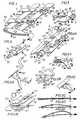
- FIG. 1shows a support designed according to the invention in the diagram
- FIG. 2shows a corresponding side view
- FIG. 3shows a side view of a support according to the invention with spacers that carry rollers
- FIGS. 4, 5, 6, 4A, 5A to C. and FIGS. 6A to Eshow various simple exemplary embodiments for a tensioning device acting on the supporting and pulling belts, diagrammatically and schematically
- FIGS. 7 to 19consistently show exemplary embodiments of a tensioning device which is fastened to pulling and supporting belts, in plan and side views or sectional views
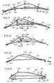
- 20 to 24show schematically and in side view further exemplary embodiments of a support according to the invention.
- 25 to 29illustrate in perspective further variants of the support according to the invention in the form of backrests.
- 30 and 31each illustrate a tensioning device which is supported by springs.
- the support designed according to the inventionconsists of two upper support bands 1, 2 and two tension bands 3, 4 underneath, which are connected at one end by one of a plurality of cross struts 5 to one another and at their other ends with a Lever shear tensioning device 10 are held together, the support straps 1, 2 being fastened to the upper cross members 11, 12 and the tension straps 3, 4 to the lower cross members 13, 14. If the spindle 15 of this clamping device is e.g.
- the tension and support bands 1 to 4are held together by some bow-shaped spacers 22 to 29, the middle spacers 24 to 27 in a common e.g. plate 30 arranged below the drawstrings are anchored and allow a greater distance between the drawstrings and support bands 1, 3 or 2.4 than the other spacers 22, 23 and 28, 29.
- the spacers 24 to 27are equipped with rollers, which rest on the support bands 1, 2.
- a lever-like handle 31engages on the plate 30, specifically with a bolt 33 passing through an elongated slot 32, the handle in the drawstring 3 having a pivot point 34 about which it can be pivoted.
- the handle 31is pivoted in the direction of the arrow 35, the plate 30 and thus all the spacers 24 to 27 are displaced upward, but when the handle 31 is pivoted in the direction of the arrow 36, the plate 30 is displaced downward.
- the support bands 1, 2 and / or the tension bands 3, 4are made of an elastic material, such as iron, sheet steel or plastic, which is essentially inextensible or non-compressible in the longitudinal direction, the support bands 1, 2 will adhere to the Tension bands 3.4 attacking tensile force in total velvet, ie bend over its entire length. However, where the distance between the spacers is greatest in the longitudinal direction of the bands, the support bands can bend the most, so that in the arrangement shown in FIG. 1, the sections 37, 38 between the spacers 24 and 26 or 25 and 27 are most curved.
- the curved sections 37, 38can also be moved up or down as desired.
- the cross struts 6 to 9are fastened to the support bands with bolts 39 to 46 so that they are at a distance from the support bands 1, 2 and allow the rollers of the displaceable spacers 24 to 27 to pass through.
- the support shown in FIG. 1is installed in a backrest of an armchair or a seat in a motor vehicle or the like and the handle 31 protrudes laterally from the backrest, so that a 31 simply by adjusting the handle Adjustment of the backrest curvature to the seated person's back can be made.
- the strength of the curvaturecan be easily adjusted by rotating a rotary handle that is also arranged laterally (not shown) on the spindle 15.
- rollers 3.4can also be arranged on the plate 30 below the drawstrings, which ensure that the plate 30 slides on the drawstrings 3, 4 without causing excessive friction.
- sliderscan also be arranged at the ends of the spacers 24 to 27 or between the tension bands 3, 4 and the plate 30.
- the handle 31can of course be replaced by a hydraulic, pneumatic or motor drive, and the actuating elements of such a drive can be arranged in the vicinity of the support or at a certain distance therefrom.
- an eccentricwhich acts directly on the plate 30 or on the handle can also be provided, the rotation of which causes the plate 30 to be displaced.
- FIG. 2shows that the spacers 24 to 27 in the position set in FIG. 1 form a curvature 47 which is approximately half the height of the support 48.
- the spacers 24 to 27are moved downward by pivoting the handle 31 in the direction of the arrow 36 (FIG. 1), the curvature 47 'indicated by dash-dotted lines will result, which is thus laid in the lowest region of the support 48 is.
- the plate 30 'is arranged between the tension bands 3, 4 and the support bands 1, 2 in such a way that the four spacers 49, 50, 51, 52 connected to it with rollers on both the support as well as on the drawstrings 1 to 4 and can slide on them when the plate 30 'is moved.
- the rolesare so small that they are not hindered in their movement on the support bands 1, 2 by the cross struts 7, 8, 9.
- a laterally protruding handle, not shown,can be attached to this plate 30 'in a similar manner to that in FIG. 1, by means of which the aforementioned adjustment of the curvature can be carried out.
- a simple lever tensioning device 53engages at the ends of two tension and support straps 1 to 4, which consists of a cross strap 56 fastened to the support straps 1, 2 with rivets 54, 55 or the like and a control belt 59 fastened with rivets 57, 58 or the like to the tension belts 3, 4, which is aligned parallel to the cross belt 56 and lies between the tension and support belts 3, 1 and 4, 2, respectively.
- the rivets 54, 55pass through long slots 60, 61 in the tension bands 3, 4 and the rivets 57, 58 pass through long slots 62, 63 in the support bands 1, 2.
- the cross belt 56 and the control belt 59are articulated at one end to a hand lever 64.
- the control band 59comprises the rivets 57, 58 from one side with wedge-shaped recesses 65, 66 and is supported on its other side on rollers 67, 68 which are fastened in the support bands 1, 2 and, if appropriate, the tension bands 3, 4 with in Long slots engaging pins can also enforce. Therefore, when the hand lever 64 is pivoted in the direction of the arrow 69, the control band 59 urges the tension bands 3, 4 in via the wedge-shaped recesses 65, 66 and the rivets 57, 58.
- the rivets 57, 58can be rotatably fastened in the drawstrings 3, 4 or provided with rotatable sleeves.
- the device 72 shown in FIG. 6can be provided, which consists of a base band 73, for example firmly connected to the support bands 1, 2 via the rollers 67, 68, and a control band 74 which can be displaced thereon and which can be designed in this way as the control band 59 of the tensioning device 53 and acts in the same way on the tension bands 3, 4 when it is pulled by turning a tension screw spindle 75, 76 in the direction of arrow 77, as indicated by arrow 78. At the end of 79 the Tension screw 75, 76 can attack a rotary knob, not shown.
- a tensioning device 80is also conceivable, as shown in FIG.
- This tensioning device 80consists of a control band 81 which is arranged between the support and tension band 1 and 3 and is oriented transversely to the latter and which lies with wedge-shaped sections 82, 83 on a roller 84, 85 of the support and tension band 1, 3 and these two bands in the sense of arrows 86, 87 moves against each other as soon as a train on the control belt 81 in the direction of arrow 88 takes effect.
- the roller 84expediently passes through the tension band 3 in a slot 89, and keeps the tension and support bands 1, 3 at a distance from one another.
- the support band 1projects with its one end 90 beyond the control band 81, which is held at least temporarily in this way between the bands 1, 3.
- a double control band 59 'can run transversely to the.
- Tension band 3 'this be arranged according to Figure 4A, but four guide rollers 57', 58 ', 57 ", 58" are arranged on a common base band 73' so that both the double control band 59 'and the tension band 3' are guided is.
- the wedge-shaped recess 65 'displaces a pin 57 "' of the tension band 3 'in the direction of arrow 70', so that a curvature in the associated support band, not shown, will result.
- basebands 73 ', 73 "etc., as shown in FIG. 4Aare strung together and, as described earlier, connected to one or more tension bands 3', 1 'via spacers, these basebands 73', 73" can function from support bands in which the desired curvature can be caused.
- an eccentric lever 81 'can be rotatably fastened on the tension band 3 "and bear against an end 2' of the support band 2" adapted to the eccentric 81 ", so that when the eccentric lever 81 'is pivoted in the direction of arrow 86' the tension band 3 "is moved in the direction of arrow 86", which slides with a pin 84 'in a slot 89' of the support band 2 ".
- a similar displacement effect for the support band 2 ′′ ′′ in FIG. 5Bresults when a lever 81 ′′ ′′ passing through the tension band 3 ′′ with its eccentric 81 ′′ ′′ swings in one or the other direction of the arrows 86 ′′, 86 ′′ is because the eccentric 81 "'then abuts either against one or the other side of a recess 65" in the support band 2 "' in an urgent manner.
- a swivel lever with a gearengages in a toothing of the tension band and, when it is rotated in one direction or the other, causes the tension band to shift relative to the support band, which in this case accommodates the bearing point of the swivel lever.
- a Bowden cable 64 'can be used according to FIG. 6A, the sleeve 64 "of which is anchored to a base and the rope 64"' of which can engage on a control band (not shown) or directly on the tension band.
- a scissor lever 53 'connected to the Bowden cablecan optionally be supported by a spindle 79 "with a handle.
- a worm drive 60 'with an eccentric disk 61'can rest against a tension band 1 ", which is displaced in the direction of arrow 77" "when the worm drive is actuated, specifically in the direction of arrow 70".
- the tension band 1 "is guided on a base band 73" via a pin engaging in a slot and will cause a curvature in the support band 4 ', to which it can be connected at the ends (not shown).
- 6C, D and Eillustrate schematically that there is a curvature over the length of the band in a central displacement position of the support and tension band and that with a further tension of the tension band in the support band, a second stronger curvature is formed between the support point and the spacer can.
- FIG. 7Another tensioning device 91 can be seen in FIG. 7.
- Two adjacent scissor lever joints 96 to 99act on adjacent and superposed tension and support bands 92 to 95, which in turn are connected at their articulation points 100, 101 with a screw spindle 102 and a nut 103 guided thereon in such a way that when the spindle knob 104 rotates, in the direction of arrow 105, the articulation points 100, 101 are moved apart and, accordingly, the drawstrings 93, 95 are moved in the direction of the arrows 106, 107.
- the desired curvaturesare formed in the support bands 92, 94, which not only can be precisely determined in their extent via the spindle rotation, but can also be fixed in the set position.
- a Bowden cable 108, 109 acting on the articulation points 100, 101 and shown in FIG. 9can also be provided with a pawl lock 111, 112 attached to an adjusting lever 110 for fixing the setting position.
- FIG. 7illustrates a tensioning device 113, which is similar to that in FIG. 7 and also has four articulated levers 114 to 117, but with opposite threads of the spindle 120 engaging in the connection articulated joints designed as nuts 118, 119, so that a rotary movement of the knob 121 in Direction of arrow 122 a movement of the Nuts 118, 119 to each other and an opposite displacement movement of the tension and support straps 123, 124 and 125, 126 results.
- FIG. 10Another simply constructed but particularly effective tensioning device 127 is illustrated in FIG. 10.
- the spindle 128passes through an end body 129 of the one tension band 130 and engages in a nut 131 which is connected in an articulated manner to the support band 133 via a tab 132.
- a further joint bracket 134is provided between the end body 129 and the bracket 132.
- the nut 131approaches the end body 129 of the tension band 130, so that the support band 133 will move in the direction of the arrow 137 because the tab 132 as a result of its articulation on the joint plate 134 transmits the movement of the nut 131 to the support band 133 in the form of a displacement in the direction 137.
- the extent and the locking of the desired curvature in the support band 133can be correctly determined.
- the spindle 128is connected in a rotationally fixed manner to another spindle 138, passes through an end body 139 of a further tension band 140 and engages in a nut 140 ', which in turn is connected in an articulated manner to a further support band 142 via a plate 141, here also between the plate 141 and the end body 139 engages a hinge plate 143, the same movement sequences result for the right part of the device in FIG. 10 as for the left part when the button 135 is set in rotation.
- the knob 135is rotated, the desired curvature can be produced and fixed both in the support band 133 and in the support band 142.
- a piston rod 144 of a piston 145can be provided according to FIG. 11, which is acted upon from one side or the other in a hydraulic cylinder 146 and thereby the control movements of the support bands 133, 142 already described above in order to form curvatures evokes.
- an eccentric lever 148is articulated on the one hand with a tension band 149 and on the other hand with a spindle 150 which is supported on an end piece 151 of an angle plate 152, one leg 153 of which is supported of the eccentric 148 serves.
- the spindle bolt 156 engaging in a slot 155also rotates the eccentric lever 148 in such a way that it moves the tension band 149 in the direction of arrow 157 relative to the support band 158 designed as a plate, so that in the support band 158 a curvature can be formed, which is also supported at one end on the leg 153 and at the other end is connected to the drawstring 149 (not shown).
- a flexible intermediate layer 159ensures a distance between the bands 158, 149; the intermediate layer 159 may be provided with a guide 160 surrounding the drawstring 149.
- the bands 149, 158are surrounded by wide enveloping bodies 161 to 163 which have at least partially wedge-shaped abutting surfaces
- the curvature in the support band 158is built up as long as it moves in the direction of the arrow 164 can be until the enveloping bodies 161 to 163 lie together with their wedge-shaped abutting surfaces. Because of their design, it is therefore possible to determine the size and position of the curvature that is to be formed in the wide enveloping bodies 161 to 163. Where an enveloping body 163 has only right-angled abutting surfaces, the curvature will at least assume a more or less elongated course due to the large radius of curvature.
- two eccentric levers 167, 168 connected to one another by a tab 166are supported on the leg 169 of a winding plate 170 and are with two.
- the underlying support band, forming a single plate 169 'only bears against the leg 169 and, depending on the degree of pivoting of the eccentric lever 167, forms a more or less large curvature.
- stripscan also be provided in which the desired curvature is generated.
- a tensioning device 173consists of an eccentric lever 174 with an eccentrically arranged slot 175, in which a pin 176 of the tension band 177 engages, which, when the eccentric lever 174 is rotated in the direction of the arrow 178 in the Slot 175 and also along the elongated slot 179 of the support band 180 moves, so that a mutual displacement takes place between the tension and support bands 177 and 180 because the support band 180 is fixed in the pivot point 181 of the eccentric lever 174.
- This displacement of the tension band 177also leads to a more or less large curvature in the support band 180, depending on how far the eccentric lever 174 is pivoted.
- FIGS. 18 and 19Another tensioning device 181 shown in FIGS. 18 and 19 also has an eccentric lever 182 which, with a circular disk 183, moves into a corresponding position Taking the support band 184 engages.
- a pin 185sits eccentrically on the disk 183 and engages in a transverse slot 186 of the tension band 187.
- the pin 185slides in the transverse slot 186 with simultaneous entrainment of the tension band 187 in the direction of arrow 189, so that the support band 184 designed in this case as a plate will curve as much as the eccentric lever 182 is pivoted.
- FIG. 1A particularly easy-to-shift curvature of a support according to the invention can be seen in FIG.
- Support and tension band 190, 191are firmly connected at one end by a rivet 192 or the like.
- Two or more spacers 193, 194can loosely or firmly enclose the bands 190, 191.
- Further spacers in the form of roller pairs 195, 196, 197, 198 held togethercan be displaced on the bands 190, 191 via an additional rigid control band 199, which acts on both pairs of rollers 195 to 198 and can be guided between the support and tension band 190, 191.
- a curve 201is formed in the support band 190 between the pairs of rollers, which, however, depends on the movement of the control band 199 in one direction or the other ( Arrow 202) can be shifted.
- the most distant curvatures formed by displacementare illustrated with a continuous line (201) and with a dashed line 203.
- the control band 199can be connected to a handle, not shown, or it can also be motor, hydraulic, electromagnetic and. Like. Be driven. Since the pairs of rollers 195 to 198 have only a low rolling resistance when they are adjusted on the belts 190, 191, their adjustment is also possible if the curvature 201 in the support belt 190 is pronounced.
- FIG. 21Another way of adjusting such a curvature within the support band is illustrated in FIG. 21.
- knee lever pairs 206, 207are attached as spacers between the support and tension band 204 and 205 and are connected to one another by arms 208, 209 and 210 in such a way that with a pivotable handle 210 'engaging the arms 208, 209, the one knee lever is stretched and the other can be bowed.
- the toggle lever 206is stretched, so that the curvature 211 is formed on the left side of the support band 204 in FIG. 21 after a force in the direction of the arrow 212 was effective on the tension band 205.
- the spacer 214 located at the fixed end of the bands 204, 205can be fixed immovably on this.
- the other spacer 215is advantageously only firmly connected to the support band 204, while the tension band 205 can slide in the spacer 215.
- toggle lever 206is fastened to the support band 204 with its tab 216. On the underside of the drawstring 205, however, the toggle levers 206, 207 engage with rollers 217, 218, which create a movement compensation when the drawstring and the support strap are moved against one another.
- a control band 219which can be operated from the outside and which can be handled like the control band 199 in FIG. 20 can also act on the toggle lever 207.
- a Bowden cable 228engages on the scissor lever 224 fixed to the support band 222 with a tab 227, the casing 229 of which is supported on the other scissor lever 225.
- the Bowden cable 228By operating the Bowden cable 228, as can be seen from the dashed line, the curvature 230 caused in the support band 222 can be shifted to the right in FIG. 22 because the scissor levers 224, 225 are brought closer to one another on one side and to one another on the other side be moved.
- a screw, an eccentric or the likecan of course also engage the relevant lever ends.
- a particularly simple embodiment of the inventionis obtained if, according to FIG. 23, a stiffness is achieved on the support belt between the support and tension belt 231, 232, which, as described above, are connected to one another and are held together by spacers 233, 234 231 engages control band 235, by the tension or pressure in one direction or the other 236, 237 a curvature 238 generated in the support band 231 by the tension band 232 can be displaced.
- the shift of the curvature to the right in FIG. 23is indicated by dashed lines.
- the tension and support band 239, 240are firmly connected at their ends with a hinge 241, 242, the upper scarving parts being held together by an articulated arm 243.
- a screw spindle 244 with handle 245engages, when it rotates in one direction the angle ⁇ 1 between the hinge parts and thus the ends of the tension and support band 239, 240 is adjusted to a larger value, for example (3 2 With such an adjustment, the angle ⁇ 1 between the parts of the other hinge 241 also changes to a smaller value, namely a 2 , so that the curvature 246 previously formed in the support band 240 is shifted to the other side of the support according to the invention, such as this is indicated by dashed lines 247. It is clear that, depending on the rotation of the screw 244, any desired intermediate position and thus any position for the curvature between the two extreme positions shown can be achieved.
- a medium wide tension band 248is connected to the same material at the top end with two side support bands 249, 250, but at the bottom end, which passes through a slot 251 of an angle piece 252, is provided with pins 253, 254, which counteract Wedge-shaped recesses 255, 256 of a slide 257 abut, which is supported on the long leg of the angle piece 252 from below and engages with a screw 258 in a thread of the short leg of the angle piece 252.
- the free ends of the support bands 249, 250are supported on the upper side of the long leg of the angle piece 252.
- U-shaped brackets 259 with rollers 260 or sliders 261are provided, against which the drawstring 248 rests (FIG. 26).
- the brackets 265can form a unit with the support bands 266, 267 and with one another slots 268 which are so wide that they can be tightened by the tension band 248 sliding on the brackets 265, i. when the greatest possible curvature of the support bands 266, 267 are closed. The webs of these brackets 265 are then supported against one another in the greatest curvature position of the support.
- the support according to the invention shown in FIG. 28consists of a backrest-shaped body 269 made of plywood, metal, plastic or the like and can be injection molded, drawn or punched. It has incisions 270, 271 directed from the bottom upwards, accommodated in soft drawstrings 272, 273, which are fastened to the body 269 with their upper ends and have pins 274, 275 at their lower free ends, which, as in the case in FIG. 25 shown embodiment of the invention against wedge-shaped recesses 276, 277 of a slide 278, which is supported and guided in the lower parts of the body 269.
- brackets 279which serve to support the drawstrings 272, 273. Therefore, if the screw spindle 280 connected to the slide 278, which engages in a thread of the body 269, is rotated and moved in the direction of the arrow 281, the pins 274, 275 and the recesses 276, 277 of the slide 278 move of the drawstrings 272, 273 in the direction of the arrows 282, so that these drawstrings 272, 273 supported by the brackets 279 are tensioned. Their tension causes a further deflection of the body 269, which may already have a curvature from the outset.
- FIG. 29An even simpler embodiment of the invention is illustrated in FIG. 29.
- a support 283, which is already curved from the outset,has rollers 284 to 291 arranged on its rear side in one or more vertical rows, around which tension bands 292, 293 are guided such that their one ends are fastened to the rollers 286 and 290 and above the others Rolls 285, 286, 284 and 287 or 289, 290, 288 and 291 e.g. laid in a zigzag shape and then guided away approximately horizontally in the lower region of the support 283 to a tensioning device, not shown.
- All or individual supportscan also have one or more "intrinsic curvatures" into which the support from can, from the outset, also in its entirety or only through individual or all support, pressure or tension elements, spacers, tensioning or control mechanisms or through additional springs or spring elements wants to return himself as soon as the influence exerted by a tensioning device ceases to exist.
- the change and / or shifting of one or more curvaturescan be brought about by "slackening instead of by tension, tensile or compressive force or by external influences (e.g. leaning), so that only a" fixation of the respective curvature e.g. by clamping, toggle or by slightly turning or releasing the control or tensioning device.
- All of the features of the invention citedcan be combined with one another or with any other structural or structural elements (directly or via damping or other aids) or exchanged as desired.
- FIG. 30shows a tensioning device 295, which is essentially that in FIG Fig. 1 corresponds to the leaf springs 296, 297, which have a degressive characteristic.
- the leaf springs 296, 297namely have an inward curvature (dashed line), into which they can never return due to stops or external hindrance.
- the starting position for the longitudinal loadis a slight opposite curvature. With further pressure load in their longitudinal direction, the leaf springs can only buckle against their inherent curvature (dash-dotted line). According to the buckling formulas, this results in a wrong spring characteristic. If the leaf springs 296, 297 rest on the tabs of the tensioning device 295 via their connecting members 298, the effect of this is supported.
- a corresponding S-shaped spring 301acts on the toggle levers of a similar tensioning device 302 and supports this in its effect, which support can of course take place in one direction or the other.
Landscapes
- Engineering & Computer Science (AREA)
- Architecture (AREA)
- Mechanical Engineering (AREA)
- Civil Engineering (AREA)
- Structural Engineering (AREA)
- Chair Legs, Seat Parts, And Backrests (AREA)
- Orthopedics, Nursing, And Contraception (AREA)
- Devices For Conveying Motion By Means Of Endless Flexible Members (AREA)
- Mattresses And Other Support Structures For Chairs And Beds (AREA)
- Springs (AREA)
- Bridges Or Land Bridges (AREA)
- Buckles (AREA)
Description
Translated fromGermanDie Erfindung betrifft eine biegsame elastische Stütze, bestehend aus mindestens einem Stütz-; band aus elastischen, in der Längserstreckung im wesentlichen undehnbarem oder nicht zusammendrückbarem Material und einem am Stützband befestigten, etwa parallel zu diesem durch Abstandhalter gehaltenem Zugband, durch dessen Spannung das Stützband mehr oder weniger krümmbar oder belastbar ist. Ein solches aus der AT-B-292 391 bekanntes Stützband aus Metall oder Kunststoff weist U-förmigen Querschnitt und an den Rändern zahlreiche durch Stanzen vorgesehene Einschnitte sowie aus der Bandmitte herausgestanzte und rechtwinkelig umgebogene Lappen auf, welche Löcher besitzen, durch die zwei Zugelemente in der Form von Seilen geführt sind. Sobald diese Zugelemente über eine Spannvorrichtung gespannt werden, kommt es zu einer Verbiegung des Stützbandes, welche entweder gleichmäßig über die Bandlänge verläuft oder infolge der an den Lochrändern hängenbleibenden Zugelemente unregelmäßige bogenförmige Abschnitte an nicht gewünschten Stellen hervorruft. Die von den Zugelementen durchsetzten umgebogenen Lappen bilden Abstandhalter für die Zugelemente gegenüber dem Stützband. Diese Abstandhalter sind in Längsrichtung des Stützbandes in gleichen Abständen angeordnet, sodaß es nicht möglich ist, an einer bestimmten Stelle des Stützbandes eine besondere Krümmung hervorzurufen oder eine solche von einer Stelle zu einer anderen zu verlagern.The invention relates to a flexible elastic support consisting of at least one support; band of elastic, in the longitudinal extent essentially inextensible or non-compressible material and attached to the support band, approximately parallel to this by spacer tape, the tension of the support band is more or less curvable or resilient. Such a support band made of metal or plastic, known from AT-B-292 391, has a U-shaped cross section and at the edges numerous incisions provided by punching as well as flaps punched out from the center of the band and bent at right angles, which have holes, through the two tension elements in in the form of ropes. As soon as these tension elements are tensioned via a tensioning device, there is a bending of the support band, which either runs evenly over the length of the band or, due to the tension elements stuck at the edges of the holes, causes irregular arcuate sections at undesired locations. The bent flaps penetrated by the tension elements form spacers for the tension elements with respect to the support band. These spacers are arranged at equal intervals in the longitudinal direction of the support band, so that it is not possible to produce a special curvature at a specific point on the support band or to move one from one point to another.
Außerdem führt der Verschleiß der seilartigen Zugelemente im Bereich der Löcher zu Beschädigungen, sodaß die Zugelemente ersetzt werden müssen.In addition, the wear of the rope-like tension elements in the area of the holes leads to damage, so that the tension elements must be replaced.
Aus der US-A-2,756,809 ist eine Rückenlehne für einen Sessel bekannt, bei welcher an einem festen Rahmen eine vordere flexible Platte und eine hintere starre Platte vorgesehen sind, wobei an der starren Platte höhenverstellbar Abstandhalter angeordnet sind, welche an der vorderen flexiblen Platte angreifen. Je nach eingestellter Länge der schraubbaren Abstandhalter und eingestellter Höhenlage bilden sich in der flexiblen Platte gekrümmte Stellen aus, wobei der Scheitelpunkt jeder Krümmung durch die eingestellte Länge dieser Abstandhalter bestimmt wird. Die für die hohle Stelle des Rückens des Benützers bestimmte Krümmung ist von dem einen längeren Abstandhalter unterstützt und aus diesem Grund verhältnismäßig steif. Bei veränderter Körperhaltung folgt diese starr eingestellte Krümmung nicht der jetzt höher oder tiefer liegenden hohlen Stelle des Rückens des Benützers, es sei denn, der betreffende Abstandhalter wird von Hand aus und zwar von einer anderen Person neuerlich auf die gewünschte Höhe eingestellt. Diese Verstellung durch eine fremde Person erfordert ein hohes Einfühlungsvermögen. Führt der Benützer jedoch selbst die Höhenverstellung des Abstandhalters durch Ergreifen der am oberen Rand der Lehne vorhandenen Stellschraube durch, so ist diese Art der Verstellung infolge der abermaligen Lageveränderung des Rückens äußerst problematisch und wird nur selten ein befriedigendes Resultat erbringen. Abgesehen davon ist der Aufbau der bekannten Lehne mit starrem Rahmen, starrer Platte, flexibler Platte, Schraubenspindeln usw. gegenüber der eingangs erwähnten elastischen Stütze verhältnismäßig kompliziert.From US-A-2,756,809 a backrest for an armchair is known in which a front flexible plate and a rear rigid plate are provided on a fixed frame, spacers which are adjustable in height and which engage the front flexible plate are arranged on the rigid plate . Depending on the set length of the screwable spacers and the set height, curved locations are formed in the flexible plate, the vertex of each curvature being determined by the set length of these spacers. The curvature intended for the hollow part of the back of the user is supported by the longer spacer and is therefore relatively stiff. When the posture changes, this rigidly adjusted curvature does not follow the hollow part of the user's back that is now higher or lower, unless the spacer in question is manually adjusted to the desired height by another person. This adjustment by a stranger requires a high level of empathy. However, if the user himself carries out the height adjustment of the spacer by grasping the adjusting screw at the upper edge of the backrest, this type of adjustment is extremely problematic due to the repeated change in the position of the back and will rarely produce a satisfactory result. Apart from this, the structure of the known backrest with a rigid frame, rigid plate, flexible plate, screw spindles etc. is relatively complicated compared to the elastic support mentioned at the beginning.
Demgegenüber ist eine aus der DE-B-1 169 625 bekannte Rückenlehne wesentlich einfacher aufgebaut, denn diese besteht aus einer starren Platte mit quergestellten Profilleisten, in welchen elastische Stahlbänder mit ihren Enden so gehalten sind, daß die sich krümmen. Aufgabe dieser Stahlbänder ist es, sich selbsttätig dem Körper des Benutzers anzupassen, damit für dessen Rücken eine bequeme und anatomisch richtige Stütze geboten wird.In contrast, a backrest known from DE-B-1 169 625 is constructed much more simply, because it consists of a rigid plate with transverse profile strips, in which elastic steel strips are held with their ends so that they curve. The task of these steel straps is to adapt themselves to the user's body, so that a comfortable and anatomically correct support is provided for their back.
Es ist also nicht Gegenstand dieser Drückschrift, eine Stütze mit willkürlich herbeigeführten Krümmungsstellen zu schaffen, sondern die gebildete Krümmung soll durch das Anlehnen des Benützers in jene Form gebracht werden, die der Rücken des Benützers selbst hat. Ein wesentlicher Nachteil dieser bekannten Rückenlehne ist die große Weichheit der gebildeten Krümmung, durch welche der Rücken des Benützers kaum unterstützt wird. Veränderungen der Krümmung des Rückens des Benützers folgt die Krümmung der Stütze ohne eine echte Stützfunktion daher auszuüben.It is therefore not the subject of this printed document to create a support with arbitrarily induced points of curvature, but rather the curvature that is formed is to be brought into the form that the back of the user himself has by leaning on the user. A major disadvantage of this known backrest is the great softness of the curvature formed, by which the back of the user is hardly supported. Changes in the curvature of the user's back are followed by the curvature of the support without therefore performing a real support function.
Aufgabe der Erfindung ist es, die eingangs erwähnte Stütze so auszubilden, daß einerseits ihre Krümmung den Rücken des Benützers so unterstützt, daß der Unterstützungseffekt auch dann gewährleistet ist, wenn der Benützer seine Rückenlage z.B. während einer längeren Sitzung (oder Autofahrt) nach oben oder unten geringfügig verändert. Anderseits soll eine bewußte Verlagerung der Krümmung der Stütze möglich sein, ohne daß komplizierte Bewegungsvorgänge ausgelöst werden.The object of the invention is to design the above-mentioned support so that, on the one hand, its curvature supports the back of the user so that the support effect is guaranteed even when the user is lying on his back, e.g. Slightly changed up or down during a long session (or car ride). On the other hand, it should be possible to deliberately shift the curvature of the support without triggering complicated movement processes.
Zur Lösung dieser Aufgabe ist die eingangs zitierte Stütze erfindungsgemäß gekennzeichnet durch eine im Scheitel unterstützungslose Krümmung des Stützbandes zwischen je zwei zueinander, voneinander oder miteinander verschiebbaren Abstandhaitern, wobei die Krümmung des Stützbandes durch das Zugband vergrößer- oder verkleinerbar und durch Verschiebung der Abstandhalter mehr oder wenigen belastbar bzw. verstellbar ist. Die so gebildete Krümmung zwischen zwei Abstandhaltern unterscheidet sich von den bekannten Rückenlehnen im wesentlichen dadurch, daß sie einerseits genügend steif ist oder so steif gemacht werden kann, um eine ausreichende Stützfunktion zu gewährleisten, anderseits aber auch so elastisch ist, daß sie geringfügigen Lageveränderungen des Rückens des Benützers zu folgen vermag und dabei die erforderliche Stützfunktion ebenfalls beibehält. Darüberhinaus ist die erfindungsgemäße Stütze wesentlich einfacher zu handhaben als etwa diejenige nach der genannten US-A-2,756,809, denn die Krümmung im Stützband kann einfach durch Betätigung des Zugbandes größer oder kleiner gemacht und dadurch mit einem einzigen Handgriff beeinflußt werden.To achieve this object, the support cited at the outset is characterized according to the invention by an unsupported curvature of the support band between two mutually, mutually or mutually displaceable spacers, the curvature of the support band being able to be enlarged or reduced by the tension band and more or a few by displacing the spacers is resilient or adjustable. The curvature thus formed between two spacers differs from the known backrests essentially in that on the one hand it is sufficiently stiff or can be made so stiff to ensure sufficient support function, but on the other hand it is also so elastic that it changes slightly in position can follow the user's back while also maintaining the required support function. In addition, the support according to the invention is much easier to handle than, for example, that according to the above-mentioned US Pat. No. 2,756,809, because the curvature in the support band can be made larger or smaller simply by actuating the tension band and can thereby be influenced in a single operation.
Ein weiterer Vorteil der Erfindung liegt darin, daß die Zug- und Stützbänder in einfacher Weise aus Stahlblech bzw. Metall, Holz, Kunststoff od. dgl. gestanzt oder gespritzt usw. und mit ebenso einfach herzustellenden Abstandhaltern zusammengefügt werden können, sodaß die erfindungsgemäße Stütze mit nur geringem Material-und Arbeitsaufwand hergestellt werden kann. Durch die Verschiebbarkeit der Abstandhalter auf Zug- und Stützband hat man es in der Hand, wo die Krümmung und in welchem Ausmaß und in welcher Gestalt sie gebildet werden soll.Another advantage of the invention is that the tension and support straps in a simple manner from sheet steel or metal, wood, plastic or the like. Stamped or injection molded, etc. and can be joined together with spacers that are just as easy to manufacture, so that the support according to the invention can be used only little material and labor can be produced. Due to the displaceability of the spacers on the tension and support band, it is in your hand where the curvature and to what extent and in what shape it should be formed.
Erfindungsgemäß ist es ferner möglich, daß zwei oder mehr Abstandhalter miteinander verbunden und gemeinsam verschiebbar sind. Damit wird nicht nur eine besonders gestaltete Krümmung im Stützband erzielt, sondern auch die Möglichkeit geschaffen, diese Krümmung ohne Formveränderung von einer Stelle zu einer anderen zu verlagern.According to the invention, it is also possible for two or more spacers to be connected to one another and to be displaceable together. This not only achieves a specially designed curvature in the support band, but also creates the possibility of moving this curvature from one point to another without changing the shape.
Die Erfindung besteht auch darin, daß die Abstandhalter zum Verschieben mit einer Handhabe oder mit einem hydraulischen, pneumatischen, motorischen oder sonstigen Antrieb oder einem Bowdenzug, einem Kniehebel, einer Stellschraube, einem Scherenhebel oder einem Exzenter versehen sind. Wenn die erfindungsgemäße Stütze bereits eingebaut oder montiert ist, können die dadurch abgedeckten Abstandhalter trotzdem durch die erwähnte Handhabe od. dgl. von außen her leicht verstellt und die Krümmung verlagert werden.The invention also consists in that the spacers for displacement are provided with a handle or with a hydraulic, pneumatic, motor or other drive or a Bowden cable, a toggle lever, a set screw, a scissor lever or an eccentric. If the support according to the invention has already been installed or installed, the spacers covered thereby can nevertheless be easily adjusted from the outside by the handle or the like mentioned and the curvature can be shifted.
Erfindungsgemäß können die Abstandhalter einfache Bügel sein, die die Stütz- und Zügbänder quer zu deren Längsrichtung umgreifen.According to the invention, the spacers can be simple brackets which encompass the support and drawstrings transversely to their longitudinal direction.
Anderseits ist es erfindungsgemäß auch möglich, daß die Abstandhalter Vorsprünge an dem Stützband oder Zugband sind, die in Ausnehmungen des Zugbandes oder Stützbandes eingreifen oder dieses durchsetzen oder umgreifen. Mit diesem Vorschlag besteht die Möglichkeit, Abstandhalter und Stütz- und Zugbänder aus einem gemeinsamen Ausgangmaterial herzustellen, wodurch sich das Befestigen separater Abstandhalter erübrigt.On the other hand, it is also possible according to the invention that the spacers are projections on the support band or tension band which engage in recesses in the tension band or support band or penetrate or encompass them. With this proposal, there is the possibility of producing spacers and support and drawstrings from a common starting material, which makes it unnecessary to attach separate spacers.
Die Erfindung besteht aber in diesem Zusammenhang auch darin, daß die Ausnehmungen des Zugbandes Schlitze sind und daß die Vorsprünge des Stützbandes in die Schlitze mit Spiel eingreifen. Mit einem solchen Spiel wird erreicht, daß bei steigender Zugkraft am Zugband eine größer werdende Krümmung vor und nach dem betreffenden Abstandhalter entsteht. Liegt der Abstandhalter einmal an dem Schlitzende des Zugbandes an, so entsteht bei einer weiteren Steigerung der Zugkraft am Zugband nur noch vor dem Abstandhalter eine Vergrößerung der Krümmung. Je nach Größe und Lage des Spiels ist natürlich eine verschieden große Belastbarkeit des Stützbandes vor und nach dem Schlitz bzw. der ganzen Stütze möglich. Durch Verlängerung oder Verkürzung der Ausnehmung sind ganz verschiedene Krümmungen oder Belastbarkeiten zu erreichen, wobei auch die Krümmungen verlagert werden können.In this context, however, the invention also consists in the fact that the recesses of the tension band are slots and that the projections of the support band engage in the slots with play. With such a game it is achieved that with increasing tensile force on the drawstring an increasing curvature occurs before and after the spacer in question. If the spacer lies against the slit end of the drawstring, then with a further increase in the tensile force on the drawstring, the curvature only increases in front of the spacer. Depending on the size and location of the game, it is of course possible for the support band to have a different load capacity before and after the slot or the entire support. By extending or shortening the recess, very different curvatures or load capacities can be achieved, and the curvatures can also be shifted.
Ein praktisches Ausführungsbeispiel der Erfindung ist dadurch gekennzeichnet, daß die oben angeführten Vorsprünge Doppelnieten oder -Schrauben, Hülsen, Scheiben u. dgl. mit einem mittleren oder mehreren separaten oder einheitlichen Abstandstücken sind, gegen welche zwei oder mehrere Stütz- und Zugbänder anliegen. Dadurch ist es möglich, handelsübliche Nieten, Schrauben, Hülsen und Beilagscheiben, Muttern, etc. einzusetzen, wodurch sich der Aufbau der erfindungsgemäßen Stütze weiter vereinfacht und verbilligt.A practical embodiment of the invention is characterized in that the above-mentioned projections double rivets or screws, sleeves, washers and. Like. Are with an average or more separate or uniform spacers against which two or more support and tension bands abut. This makes it possible to use commercially available rivets, screws, sleeves and washers, nuts, etc., which further simplifies and reduces the cost of the support according to the invention.
Ein anderes Merkmal der Erfindung zeichnet sich dadurch aus, daß das Spiel zwischen den Abstandhaltern des Stützbandes und den Schlitzen des Zugbandes unterschiedlich groß ist. Auch in diesem Fall ist je nach Größe des Spiels eine verschieden große Belastbarkeit der Stütze erreichbar, aber auch an verschiedenen Stellen des Stützbandes je nach Wunsch festlegbar. Selbstverständlich kann auch ein linearer, progressiver oder degressiver Anstieg der Spielgröße im Zugband vorgenommen werden, um die Belastbarkeit der Stütze in linearer Weise oder anders festzulegen.Another feature of the invention is characterized in that the play between the spacers of the support band and the slots of the tension band is different. In this case too, depending on the size of the game, a different load capacity of the support can be achieved, but can also be determined at different points on the support band as desired. Of course, a linear, progressive or degressive increase in the play size in the tension band can also be carried out in order to determine the load-bearing capacity of the support in a linear manner or otherwise.
Nach einem weiteren Vorschlag besteht die Erfindung darin, daß im Bereich des Vorsprunges eine keilförmige Ausnehmung, ein Exzenter oder Kniehebel aus zusammendrückbarem oder nicht zusammendrückbarem bzw. dehnbarem Material oder ein pneumatisches, hydraulisches oder motorisches Antriebselement mit direkter oder ferngesteuerter Handhabe ein- oder angreift, deren eingestellte Lage entweder direkt oder indirekt (durch Fremdmittel) steuerbar bzw. fixierbar ist. Damit hat man es in der Hand, mit verhältnismäßig einfachen Mitteln eine Verschiebung der Zug- und Stützbänder gegeneinander an bestimmten Stellen einzuleiten, wodurch eine eigene Spannvorrichtung für das Zugband entbehrlich sein kann. Wird aber seine Spannvorrichtung eingesetzt, so kann diese in ihrer Wirkung durch die erwähnten Mittel an verschiedenen Stellen des Stützbandes verstärkt oder vermindert werden.According to a further proposal, the invention consists in that a wedge-shaped recess, an eccentric or toggle lever made of compressible or non-compressible or stretchable material or a pneumatic, hydraulic or motor drive element with a direct or remote-controlled handle engages or engages in the area of the projection, whose set position can be controlled or fixed either directly or indirectly (by external means). This means that it is possible to initiate a displacement of the tension and support straps against each other at certain points using relatively simple means, which means that a separate tensioning device for the tension strap can be dispensed with. If, however, its tensioning device is used, its effectiveness can be increased or decreased in various places on the support band by the means mentioned.
Die Erfindung beinhaltet ferner das wesentliche Merkmal, daß an dem Vorsprung bzw. Abstandhalter des Stützbandes eine am Zugband gehaltene Stellschraube, eine keilförmige Ausnehmung, ein Exzenter od. dgl. direkt oder über ein zusätzliches innen oder außen liegendes Steuerband angreift. Dieses weitere Steuerband trägt daher Stellschrauben, eine keilförmige Ausnehmung oder einen Exzenter und ist von einer Stelle aus bedienbar, wobei man sich Schlitze im Zugband erspart, da ja die Abstandhalter direkt mit den zugeordneten Schrauben, keilförmigen Ausnehmungen oder mit den Exzentern zusammenarbeiten und über das Steuerband beeinflußbar sind.The invention also includes the essential feature that a set screw held on the drawstring, a wedge-shaped recess, an eccentric or the like acts on the projection or spacer of the support band directly or via an additional control band located inside or outside. This further control band therefore carries set screws, a wedge-shaped recess or an eccentric and can be operated from one point, with slots in the tension band saved, since the spacers work directly with the assigned screws, wedge-shaped recesses or with the eccentrics and can be influenced via the control band.
Die Erfindung ist ferner dadurch gekennzeichnet, daß eine Spannvorrichtung einerseits an einem oder an mehreren Zugbändern und anderseits an den Stützbändern angreift. Mit einer solchen Spannvorrichtung ist innerhalb einiger oder aller Zug- und Stützbänder eine mehr oder weniger große Krümmung, und zwar über die ganze Länge oder Teile der Stütze, herstellbar. Die Spannvorrichtung wird dann zweckmäßig sein, wenn zum Spannen der Stütze große Kräfte benötigt werden oder wenn gegenüber den Abstandhaltern und deren Steuerung eine gegenläufige, ergänzende, pulsierende od. dgl. Gesamt-oder Teilwölbung oder -Belastbarkeit, eine Schwingung od. dgl. gesteuert werden soll.The invention is further characterized in that a tensioning device acts on the one hand on one or more tension bands and on the other hand on the support bands. With such a tensioning device, a more or less large curvature can be produced within some or all of the tension and support straps, namely over the entire length or parts of the support. The tensioning device will be expedient if large forces are required to tension the support or if a counter-rotating, supplementary, pulsating or similar total or partial curvature or loading, an oscillation or the like are controlled in relation to the spacers and their control should.
Ein anderes Merkmal der Erfindung besteht darin, daß die Zugbänder oder ein zusätzliches Zugband z.B. etwa in der halben Länge der Stützbänder od. dgl. an diesen oder an anderen Teilen angreifen. Damit können « Teile des Stützbandes unbeeinflußt bleiben oder anders als der übrige Teil beeinflußt werden, wobei durch Verwendung eines oder mehrerer zusätzlicher Zugbänder eine Verlagerung der Krümmung oder eine Änderung der Belastbarkeit, der Elastizität der Stütze oder eines Stützenteiles möglich ist.Another feature of the invention is that the drawstrings or an additional drawstring e.g. attack about half the length of the support straps or the like on these or other parts. This allows parts of the support band to remain unaffected or to be influenced differently from the rest of the part, it being possible to shift the curvature or to change the load capacity, the elasticity of the support or a support part by using one or more additional drawstrings.
Erfindungsgemäß ist es ferner möglich, daß eine oder mehrere Spannvorrichtungen an einem oder an mehreren Stütz- und Zugbändern oder Gruppen derselben angreifen. Die Krümmung einer so ausgebildeten Stütze kann in beliebiger Variation und Kombination erfolgen.According to the invention, it is also possible for one or more tensioning devices to engage one or more support and tension bands or groups thereof. A support designed in this way can be curved in any variation and combination.
Die Erfindung besteht auch darin, daß als Spannvorrichtung an den Stütz- oder Zugbändern ein Bowdenzug, Gelenkhebel, Keil, Exzenterhebel, eine Gewindespindel oder eine Druck- oder Zugfeder, ein hydraulischer, pneumatischer oder motorischer Antrieb, eine automatische Steuerung durch Luftdruck, Fotozelle, Schwerkraft, Fliehkraft und andere äußere Einflüsse angreift. Damit können einfache, raum-und kostensparende, aber wirkungsvolle Mittel eingesetzt werden, während bei hohem Kraftbedarf die anderen Antriebsarten zum Einsatz gebracht werden, wobei z.B. bei der Fernsteuerung von in Sitzlehnen eingebauten Stützen eine wesentliche Komfortsteigerung erzielt wird.The invention also consists in that a bowden cable, articulated lever, wedge, eccentric lever, a threaded spindle or a compression or tension spring, a hydraulic, pneumatic or motor drive, an automatic control by air pressure, photo cell, gravity as a tensioning device on the support or tension bands , Centrifugal force and other external influences. This means that simple, space-saving and cost-saving, but effective means can be used, while the other drive types are used when the power is high, e.g. a substantial increase in comfort is achieved when remotely controlling supports installed in seat backrests.
Die Erfindung zeichnet sich auch dadurch aus daß zwischen den unmittelbar benachbarten übereinander oder nebeneinander liegenden Zug- und Stützbändern durchgehend gleich lange oder verschieden lange Abstandshalter eingesetzt sind. Damit können einzelne oder mehrere Krümmungen schon bei der Herstellung und Festigstellung der Stütze fixiert werden.The invention is also characterized in that spacers are used for the same length or different lengths between the immediately adjacent tension and support bands lying one above the other or one next to the other. Single or multiple curvatures can thus be fixed during the manufacture and fixing of the support.
Ein besonderes Ausführungsbeispiel der Erfindung ist dadurch gekennzeichnet, daß als Abstandhalter ein die Zug- und Stützbänder umgebender Schlauch mit einem an einer oder mehreren Stellen erweiterten Hohlraum vorgesehen ist, in welchen ein Abschnitt des Stützbandes im gespannten Zustand eingreift. Durch die Verwendung eines einheitlichen Schlauches an Stelle der einzelnen Abstandhalter wird eine weitere Vereinfachung der Stütze erreicht, wobei aber mit gleichem Efflekt eine Krümmung an einer bestimmten Stelle hervorgerufen werden kann. Dabei ist es erfindungsgemäß besonders vorteilhaft, wenn der Schlauch auf den Zug- und Stützbändern in Längsrichtung verschiebbar oder um seine Längsachse verdrehbar angeordnet ist, weil mit dieser Maßnahme eine Verlagerung der Krümmung von einer Stelle zur anderen leicht und bequem bewerkstelligt werden kann.A special embodiment of the invention is characterized in that a hose surrounding the tension and support bands is provided as a spacer with a cavity expanded at one or more points, in which a section of the support band engages in the tensioned state. The use of a uniform tube instead of the individual spacers further simplifies the support, but a curvature can be caused at a certain point with the same effect. It is particularly advantageous according to the invention if the hose is arranged to be displaceable in the longitudinal direction or rotatable about its longitudinal axis on the tension and support belts, because with this measure a displacement of the curvature from one location to another can be accomplished easily and comfortably.
Erfindungsgemäß ist es ferner möglich, daß zwischen den Abstandhaltern und den Stütz- und Zugbändern ein Gleitmaterial oder Rollen angeordnet sind. Diese Ausführungsform der Erfindung wird man dort anwenden, wo man selbst unter Belastung eine Verlagerung der Krümmung vornehmen können muß. Als zweckmäßig hat es sich dabei erwiesen, daß an den Rollen der Abstandshalter anstelle eines Bandes ein Seil, eine Kette oder ein ähnliches Zugelement anliegt bzw. durch die Rollen geführt ist.According to the invention it is also possible that a sliding material or rollers are arranged between the spacers and the support and tension bands. This embodiment of the invention will be used wherever it is necessary to be able to shift the curvature even under load. It has proven to be expedient that a rope, a chain or a similar tension element rests on the rollers of the spacers instead of a band or is guided through the rollers.
Ein anderes wesentliches Erfindungsmerkmal besteht darin, daß die Stützbänder eine gitterförmige, aus einem Materialstück herausgestanzte Einheit oder eine Platte bilden und daß die Zugbänder entweder Vorsprünge an der Platte durchsetzen oder durch Abstandhalter an der Platte gehalten sind. Damit ergibt sich eine besonders einfache Herstellungsart für die erfindungsgemäßen Stützen, die untereinander nicht mehr separat verbunden werden müssen.Another essential feature of the invention is that the support bands form a lattice-shaped unit or a plate punched out of a piece of material and that the drawstrings either penetrate protrusions on the plate or are held on the plate by spacers. This results in a particularly simple type of manufacture for the supports according to the invention, which no longer have to be connected to one another separately.
Die Erfindung kann auch darin erblickt werden, daß die Zugbänder lediglich an den einen Enden oder an anderen Stellen der gitterförmigen Einheit oder Platte angreifen und gegebenenfalls mit einer Spannvorrichtung verbunden sind.The invention can also be seen in that the drawstrings only engage at one end or at other points of the lattice-shaped unit or plate and are optionally connected to a tensioning device.
Erfindungsgemäß ist es auch möglich, daß ein mittleres Zugband zwei äußeren Stützbändern benachbart ist, daß das mittlere Zugband und die äußeren Stützbänder an einem Ende miteinander verbunden sind, daß das andere Ende des mittleren Zugbandes mit einer Spannvorrichtung verbunden ist sowie die anderen Enden der äußeren Stützbänder im Bereich der Spannvorrichtung abgestützt sind und daß die Abstandhalter U-förmige, an den Stützbändern befestigte und das Zugband mit ihren Stegen untergreifende Bügel sind, wobei die Stege mit Rollen und/oder mit Gleitstücken versehen sind. Diese Ausführungsform der Erfindung ist besonders einfach zu verwirklichen, da nur von einem gemeinsamen Körper ausgegangen werden muß, der Zug- und Stützbänder beinhaltet und z.B. aus Kunststoff durch Spritzen hergestellt werden kann. Ebenso einfach sind die zugehörigen Bestandteile für den Verstellmechanismus. Die Erfindung sieht nämlich auch vor, daß das mittlere Zugband mit Stützbändern verbunden ist, die mit U-förmigen Bügeln eine bauliche Einheit bilden, daß zwischen den einzelnen Bügeln Querschlitze vorgesehen sind, die schmäler, breiter, länger, kürzer als oder gleich breit wie die Bügel sind und daß die Bügel im Bereich der Spannvorrichtung höher, niedriger oder gleichhoch wie die Bügel sind, welche sich an das gemeinsame Ende für Zug-und Stützbänder anschließen und daß die Spannvorrichtung aus einem Winkelstück mit Langschlitz für den Durchtritt des Zugbandes und einem quer zum Zugband über eine Schraubenspindel od. dgl. verstellbaren Schieber besteht, der an der einen Seite des den Langschlitz aufweisenden Schenkels des Winkelstücks anliegt, daß an der anderen Seite des Schenkels die Stützbänder abgestützt sind und daß Zapfen an dem den Langschlitz des Schenkels durchsetzenden Ende des Zugbandes gegen keilförmige Ausnehmungen des Schiebers anliegen, wobei die Schraubenspindel in. ein Gewinde des kurzen rechtwinkelig abgebogenen Schenkels des Winkelstückes eingreift oder durch einen Exzenter betätigbar ist.According to the invention, it is also possible that a middle tension band is adjacent to two outer support bands, that the middle tension band and the outer support bands are connected at one end, that the other end of the middle tension band is connected to a tensioning device and the other ends of the outer support bands are supported in the area of the tensioning device and that the spacers are U-shaped brackets which are fastened to the support straps and which engage under the drawstring with their webs, the webs being provided with rollers and / or with sliders. This embodiment of the invention is particularly easy to implement, since it is only necessary to start from a common body which contains tension and support straps and can be produced, for example, from plastic by injection molding. The associated components for the adjustment mechanism are just as simple. The invention also provides that the middle drawstring is connected to support straps which form a structural unit with U-shaped brackets, that transverse slots are provided between the individual brackets can be seen which are narrower, wider, longer, shorter than or the same width as the stirrups and that the stirrups in the area of the tensioning device are higher, lower or the same height as the stirrups which connect to the common end for tension and support straps and that the tensioning device consists of an angle piece with an elongated slot for the passage of the tension band and a slide which is adjustable transversely to the tension tape via a screw spindle or the like and which bears on one side of the leg of the angle piece which has the elongated slot, that on the other side of the leg the support straps are supported and that pins rest against the wedge-shaped recesses of the slide at the end of the drawstring passing through the long slot of the leg, the screw spindle engaging in a thread of the short right-angled leg of the contra-angle handpiece or being actuatable by an eccentric.
Eine andere noch einfachere Variante der Erfindung ist dadurch gekennzeichnet, daß ein etwa rückenlehnenförmiger Körper einen oder mehrere in seiner Längsrichtung von unten nach oben verlaufende Einschnitte aufweist, daß die Einschnitte zur Aufnahme von Zugbändern dienen, die an ihren einen Enden am rückenlehnenförmigen Körper befestigt, mit ihren anderen Enden an einer Spannvorrichtung fixiert und über ihre ganze Länge von Anstandhaltern unterstützt sind, die U-förmig ausgebildet und an der Vorder- oder Rückenseite des rückenlehnenförmigen Körpers befestigt bzw. geführt öder in einem Stück mit ihm oder mit den Zugbändern gefertigt sind. Anderseits ist es erfindungsgemäß möglich, daß die Spannvorrichtung aus einem im rückenlehnenförmigen Körper quer zu dessen Längsrichtung geführten Schieber mit keilförmigen Ausnehmungen und einer oder mehreren je ein Gewinde des rückenlehnenförmigen Körpers durchsetzenden Schraubenspindel besteht und daß an den keilförmigen Ausnehmungen Stifte der Zugbänder anliegen. Schließlich kann die Erfindung noch einfacher ausgeführt sein und darin liegen, daß die Platte an ihrer Rückseite im Abstand voneinander angeordnete Rollen besitzt, daß Zugseile oder Zugbänder an jeweils einer der Rollen oder an der Platte fixiert, um die übereinander angeordneten Rollen zick-zackartig gelegt und zweckmäßig von einer Rolle am unteren Rand der Platte zu einer Spannvorrichtung geführt sind. Daraus ist zu ersehen, daß für diese Variante der Erfindung der geringste Materialaufwand erforderlich ist.Another even simpler variant of the invention is characterized in that an approximately backrest-shaped body has one or more incisions running in the longitudinal direction from bottom to top, that the incisions serve to receive tension bands which are attached at one end to the backrest-shaped body their other ends are fixed to a tensioning device and are supported over their entire length by spacers which are U-shaped and fastened or guided on the front or back side of the backrest-shaped body or are produced in one piece with it or with the drawstrings. On the other hand, it is possible according to the invention that the tensioning device consists of a slide with wedge-shaped recesses and one or more screw threads penetrating a thread of the backrest-shaped body in the backrest-shaped body transversely to its longitudinal direction and that pins of the drawstrings rest on the wedge-shaped recesses. Finally, the invention can be made even simpler and lie in the fact that the plate has rollers arranged at a distance from one another on its rear side, that traction cables or tension bands are fixed to each of the rollers or on the plate in order to place the rollers arranged one above the other in a zigzag fashion and are expediently guided from a roller at the lower edge of the plate to a tensioning device. It can be seen from this that the least amount of material is required for this variant of the invention.
Die Erfindung ist in der Zeichnung an Hand einiger Ausführungsbeispiele näher veranschaulicht. Es zeigen Fig. 1 eine erfindungsgemäß ausgebildete Stütze im Schaubild, Fig. 2 eine entsprechende Seitenansicht, schematisch, Fig.3 3 eine Seitenansicht einer erfindungsgemäßen Stütze mit Abstandhaltern, die Rollen tragen, Fig. 4, 5, 6, 4A, 5A bis C und 6A bis E verschiedene einfache Ausführungsbeispiele für eine an den Stütz- und Zugbändern angreifende Spannvorrichtung schaubildlich und schematisch und Fig.7 bis 19 durchwegs Ausführungsbeispiele einer Spannvorrichtung, die an Zug- und Stützbändern befestigt ist und zwar in Drauf- und Seitenansichten bzw. Schnittdarstellungen. Die Fig. 20 bis 24 zeigen schematisch und in Seitenansicht weitere Ausführungsbeispiele einer erfindungsgemäßen Stütze. Die Fig. 25 bis 29 veranschaulichen perspektivisch weitere Varianten der erfindungsgemäßen Stütze in der Form von Rückenlehnen. Die Fig.30 und 31 veranschaulichen je eine Spannvorrichtung, die durch Federn unterstützt werden.The invention is illustrated in more detail in the drawing with the aid of a few exemplary embodiments. 1 shows a support designed according to the invention in the diagram, FIG. 2 shows a corresponding side view, schematically, FIG. 3 shows a side view of a support according to the invention with spacers that carry rollers, FIGS. 4, 5, 6, 4A, 5A to C. and FIGS. 6A to E show various simple exemplary embodiments for a tensioning device acting on the supporting and pulling belts, diagrammatically and schematically, and FIGS. 7 to 19 consistently show exemplary embodiments of a tensioning device which is fastened to pulling and supporting belts, in plan and side views or sectional views. 20 to 24 show schematically and in side view further exemplary embodiments of a support according to the invention. 25 to 29 illustrate in perspective further variants of the support according to the invention in the form of backrests. 30 and 31 each illustrate a tensioning device which is supported by springs.
Der Fig. 1 ist zu entnehmen, daß die erfindungsgemäß ausgebildete Stütze aus zwei oberen Stützbändern 1,2 und zwei darunterliegenden Zugbändern 3,4 besteht, welche an ihren einen Enden durch eine von mehreren Querstreben 5 bis miteinander verbunden und an ihren anderen Enden mit einer Hebelscherenspannvorrichtung 10 zusammengehalten werden, wobei die Stützbänder 1,2 an den oberen Querteilen 11, 12 und die Zugbänder 3,4 an den unteren Querteilen 13, 14 befestigt sind. Wird die Spindel 15 dieser Spannvorrichtung z.B. im Drehsinn des Pfeiles 16 mittels einer nicht dargestellten Kurbel oder einem Griff gedreht, so werden die an einem mittleren, von der Spindel durchsetzten Gewindeteil 17 angelenkten Scherenhebel 18, 19, 20, 21 in ihre gestreckte Lage gebracht, sodaß die mit ihnen gelenkig verbundenen Querteile 11 bis 14 auseinandergedrängt werden. Durch diese Bewegung kommt an den Zugbändern 3,4 eine Zugkraft zur Wirkung, durch welche die Stützbänder 1,2 in die dargestellte Lage aufgebogen werden.1 that the support designed according to the invention consists of two
Die Zug- und Stützbänder 1 bis 4 sind durch einige bügelförmige Abstandhalter 22 bis 29 zusammengehalten, wobei die mittleren Abstandhalter 24 bis 27 in einer gemeinsamen z.B. unterhalb der Zugbänder angeordneten Platte 30 verankert sind und einen größeren Abstand zwischen den Zug- und Stützbändern 1,3 bzw. 2,4 zulassen als die anderen Abstandhalter 22, 23 und 28, 29. Außerdem sind die Abstandhalter 24 bis 27 mit Rollen ausgestattet, welche auf den Stützbändern 1,2 aufliegen.The tension and
An der Platte 30 greift eine hebelartige Handhabe 31 an und zwar mit einem einen Langschlitz 32 durchsetzenden Bolzen 33, wobei die Handhabe in dem Zugband 3 einen Drehpunkt 34 hat, um welchen sie geschwenkt werden kann. Bei einer Verschwenkung der Handhabe 31 in Richtung des Pfeiles 35 verlagert sich die Platte 30 und somit alle Anstandhalter 24 bis 27 nach oben, bei einer Verschwenkung der Handhabe 31 in Richtung des Pfeiles 36 jedoch kommt es zu einer Verlagerung der Platte 30 nach unten.A lever-
Da die Stützbänder 1,2 und/oder auch die Zugbänder 3,4 aus einem elastischen, in der Längserstreckung im wesentlichen nicht dehnbaren oder nicht zusammendrückbarem Material, z.B. Eisen, Stahlblech oder Kunststoff bestehen, werden sich die Stützbänder 1,2 bei einer an den Zugbändern 3,4 angreifenden Zugkraft insgesamt, d.h. über ihre ganze Länge durchbiegen. Dort jedoch, wo der Abstand zwischen den Abstandhaltern in Längsrichtung der Bänder am größten ist, können sich die Stützbänder am meisten krümmen, sodaß bei der in Fig. 1 gezeigten Anordnung die Abschnitte 37, 38 zwischen den Abstandhaltern 24 und 26 bzw. 25 und 27 am stärksten gekrümmt sind.Since the
Durch das bereits erwähnte Verschwenken der Handhabe 31 und Verschieben der Abstandhalter 24 bis 27 können aber auch die gekrümmten Abschnitte 37, 38 je nach Wunsch nach oben oder nach unten verlagert werden.By pivoting the
Die Querstreben 6 bis 9 sind an den Stützbändern mit Bolzen 39 bis 46 so befestigt, daß sie von den Stützbändern 1,2 einen Abstand haben und das Passieren der Rollen der verschiebbaren Abstandhalter 24 bis 27 gestatten.The cross struts 6 to 9 are fastened to the support bands with
Man kann sich leicht vorstellen, daß die in Fig. 1 dargestellte Stütze in einer Rückenlehne eines Sessels oder eines Sitzes in einem Kraftfahrzeug od. dgl. eingebaut ist und die Handhabe 31 seitlich aus der Rückenlehne herausragt, so daß durch einfaches Verstellen der Handhabe 31 eine Anpassung der Lehnenkrümmung an den Rücken der sitzenden Person vorgenommen werden kann. Dabei kann die Stärke der Krümmung durch Verdrehung eines ebenfalls seitlich angeordneten (nicht dargestellten) auf der Spindel 15 sitzenden Drehgriffes mühelos eingestellt werden.It can easily be imagined that the support shown in FIG. 1 is installed in a backrest of an armchair or a seat in a motor vehicle or the like and the
Durch die Anordnung der Rollen an den Abstandhaltern 24 bis 27 ist es möglich, eine Verlagerung der gekrümmten Abschnitte 37, 38 auch dann vorzunehmen, wenn die Zugbänder 3,4 durch die Hebelscherenspannvorrichtung 10 gespannt sind. Außer den gezeigten Rollen können auch unterhalb der Zugbänder 3,4 Rollen an der Platte 30 angeordnet sein, die ein Gleiten der Platte 30 an den Zugbändern 3,4 ohne daß eine allzu große Reibung hervorgerugen wird, gewährleisten.The arrangement of the rollers on the
Anstelle der erwähnten Rollen können auch Gleitstücke an den Enden der Abstandhalter 24 bis 27 bzw. zwischen den Zugbändern 3,4 und der Platte 30 angeordnet sein.Instead of the rollers mentioned, sliders can also be arranged at the ends of the
Die Handhabe 31 kann natürlich durch einen hydraulischen, pneumatischen oder motorischen Antrieb ersetzt sein, wobei die Betätigungselemente eines solchen Antriebs in der Nähe der Stütze oder in einer bestimmten Entfernung von dieser angeordnet sein können. Es kann aber auch ein an der Platte 30 direkt oder an der Handhabe angreifender Exzenter vorgesehen sein, bei dessen Drehbewegung die Verschiebung der Platte 30 hervorgerufen wird.The
. Dem in Fig.2 dargestellten Ausführungsbeispiel ist zu entnehmen, daß die Abstandhalter 24 bis 27 in der in Fig. 1 eingestellten Lage eine Krümmung 47 bilden, die etwa in der halben Höhe der Stütze 48 liegt. Sind die Abstandhalter 24 bis 27 jedoch durch Verschwenkung der Handhabe 31 in Richtung des Pfeiles 36 (Fig. 1) nach unten verschoben, so wird sich die durch strichpunktierte Linien angedeutete Krümmung 47' ergeben, die auf diese Weise im untersten Bereich der Stütze 48 verlegt ist.. The embodiment shown in FIG. 2 shows that the
Bei der in der Fig. gezeigten Ausführungsform ist die Platte 30' zwischen den Zugbändern 3,4 und den Stützbändern 1,2 angeordnet, derart, daß die vier mit ihr verbundenen Abstandhalter 49, 50, 51, 52 mit Rollen sowohl an den Stütz- als auch an den Zugbändern 1 bis 4 abgestützt sind und dadurch auf diesen gleiten können, wenn die Platte 30' verschoben wird. Die Rollen sind so klein, daß sie bei ihrer Bewegung auf den Stützbändern 1, 2 durch die Querstreben 7, 8, 9 nicht behindert sind. An dieser Platte 30' kann eine seitlich abstehende nicht dargestellte Handhabe in ähnlicher Weise wie in Fig. 1 befestigt sein, mittels welcher die erwähnte Verstellung der Krümmung vorgenommen werden kann.In the embodiment shown in the figure, the plate 30 'is arranged between the
Bei der in Fig. 4 schaubildlich dargestellten Stütze greift an den Enden von je zwei Zug- und Stützbändern 1 bis 4 eine einfache Hebelspannvorrichtung 53 an, die aus einem an den Stützbändern 1,2 mit Nieten 54, 55 od. dgl. befestigten Querband 56 und'einem mit Nieten 57, 58 od. dgl. an den Zugbändern 3,4 befestigten Steuerband 59 besteht, das parallel zum Querband 56 ausgerichtet ist und so wie dieses zwischen den Zug-und Stützbändern 3,1 bzw. 4,2 liegt. Die Nieten 54, 55 durchsetzen Langschlitze 60, 61 in den Zugbändern 3,4 und die Nieten 57, 58 durchsetzen Langschlitze 62, 63 in den Stützbändern 1,2. Das Querband 56 und das Steuerband 59 sind an ihren einen Enden mit einem Handhebel 64 gelenkig verbunden.In the support shown diagrammatically in FIG. 4, a simple
Das Steuerband 59 umfaßt die Nieten 57, 58 von einer Seite her mit keilförmigen Ausnehmungen 65, 66 und ist an seiner anderen Seite an Rollen 67, 68 abgestützt, die in den Stützbändern 1, 2 befestigt sind und gegebenenfalls die Zugbänder 3, 4 mit in Langschlitze eingreifenden Stiften ebenfalls durchsetzen können. Wenn daher der Handhebel 64 in Richtung des Pfeiles 69 verschwenkt wird, drängt das Steuerband 59 die Zugbänder 3, 4 über die keilförmigen Ausnehmungen 65, 66 und die Nieten 57, 58 in . Richtung der Pfeile 70, 71, wobei die Nieten 57, 58 in den Langschlitzen 62, 63 der durch das Querband 56 gehaltenen Stützbänder 1, 2 und die Nieten 54, 55 ihrerseits in den Langschlitzen 60, 61 der bewegten Zugbänder 3, 4 gleiten.The
Zur Erleichterung dieses Spannvorganges können die Nieten 57, 58 drehar in den Zugbändern 3, 4 befestigt oder mit drehbaren Hülsen versehen sein.To facilitate this clamping process, the
Anstelle der Spannvorrichtung 53 kann die in Fig.6 dargestellte Vorrichtung 72 vorgesehen sein, welche aus einem z.B. mit den Stützbändern 1, 2 über die Rollen 67, 68 fest verbundenen Basisband 73 und einem auf diesen verschiebbaren Steuerband 74 besteht, welches so ausgebildet sein kann wie das Steuerband 59 der Spannvorrichtung 53 und in gleicher Weise auf die Zugbänder 3, 4 einwirkt, wenn es durch Drehen einer Zugschraubenspindel 75, 76 in Pfeilrichtung 77 herangezogen wird, wie dies durch den Pfeil 78 angedeutet ist. Am Ende 79 der Zugschraubenspindel 75, 76 kann ein nicht dargestellter Drehknopf angreifen. Es ist aber auch eine Spannvorrichtung 80 denkbar, wie sie in Fig. dargestellt ist. Diese Spannvorrichtung 80 besteht aus einem zwischen Stütz- und Zugband 1 und 3 angeordneten und quer zu diesen ausgerichteten Steuerban 81, das mit keilförmigen Abschnitten 82, 83 an je einer Rolle 84, 85 des Stütz-und Zugbandes 1, 3 anliegt und diese beiden Bänder im Sinne der Pfeile 86, 87 gegeneinander verschiebt, sobald ein Zug an dem Steuerband 81 in Richtung des Pfeiles 88 wirksam wird.Instead of the
Die Rolle 84 durchsetzt dabei zweckmäßig das Zugband 3 in einem Schlitz 89, und hält Zug- und Stützband 1, 3 im Abstand voneinander. Das Stützband 1 überragt mit seinem einen Ende 90 das Steuerband 81, das auf diese Weise zwischen den Bändern 1, 3 zumindest zeitweilig gehalten ist.The
In ähnlicher Weise wie bei der Vorrichtung nach Fig. 4 kann ein Doppelsteuerband 59' quer zum. Zugband 3' dieses umfassend gemäß Fig.4A angeordnet sein, wobei allerdings auf einer gemeinsamen Basisband 73' vier Führungsrollen 57', 58', 57", 58" so angeordnet sind, daß sowohl das Doppelsteuerband 59' als auch das Zugband 3' geführt ist. Das Doppelsteuerband 59' kann mit einer Zugschraubenspindel 75', 76' ähnlich wie in Fig. 6 verbunden sein, die an dem Basisband 73' verankert ist und bei einer Verdrehung ihres Endes 79' in Richtung des Pfeiles 77' eine Verschiebung des Doppelsteuerbandes 59' in Richtung des Pfeiles 78' bewirken. Dabei verschiebt die keilförmige Ausnehmung 65' einen Stift 57"' des Zugbandes 3' in Richtung des Pfeiles 70', so daß eine Krümmung in dem nicht dargestellten zugehörigen Stützband die Folge sein wird.In a manner similar to that of the device according to FIG. 4, a double control band 59 'can run transversely to the. Tension band 3 'this be arranged according to Figure 4A, but four
Wenn man mehrere Basisbänder 73', 73" usw. wir in Fig.4A dargestellt, aneinanderreiht und, wie früher beschrieben, mit einem oder mehreren Zugbändern 3', 1' über Abstandhalter verbindet, so können diese Basisbänder 73', 73" die Funktion von Stützbändern übernehmen, in denen die gewünschte Krümmung hervorgerufen werden kann.If
Gemäß Fig. 5A kann ein Exzenterhebel 81' auf dem Zugband 3" drehbar befestigt sein und gegen ein an den Exzenter 81" angepaßtes Ende 2' des Stützbandes 2" anliegen, so daß bei einer Verschwenkung des Exzenterhebels 81' in Richtung des Pfeiles 86' das Zugband 3" in Richtung des Pfeiles 86" bewegt wird, das mit einem Stift 84' in einem Schlitz 89' des Stützbandes 2" gleitet.5A, an eccentric lever 81 'can be rotatably fastened on the
Eine gleichartige Verschiebewirkung für das Stützband 2''' in Fig.5B ergibt sich, wenn ein das Zugband 3"' mit seinem Exzenter 81"' durchsetzender Hebel 81"" in der einen oder anderen Richtung der Pfeile 86", 86"' verschwenkt wird, weil der Exzenter 81"' sodann entweder gegen die eine oder gegen die andere Seite einer Ausnehmung 65" im Stützband 2"' in drängender Weise anliegt.A similar displacement effect for the
Gemäß Fig. 5C greift ein Schwenkhebel mit Zahnrad in eine Verzahnung des Zugbandes ein und bewirkt bei seiner Verdrehung in der einen oder anderen Richtung eine Verschiebung des Zugbandes gegenüber dem Stützband, das in diesem Falle die Lagerstelle des Schwenkhebels aufnimmt.According to FIG. 5C, a swivel lever with a gear engages in a toothing of the tension band and, when it is rotated in one direction or the other, causes the tension band to shift relative to the support band, which in this case accommodates the bearing point of the swivel lever.
Als Alternative zur Zugschraubenspindel der Fig. kann gemäß Fig.6A ein Bowdenzug 64' verwendet werden, dessen Hülle 64" an einer Basis verankert und dessen Seil 64"' an einem nicht dargestellten Steuerband oder direkt am Zugband angreifen kann. Ein mit dem Bowdenzug verbundener Scherenhebel 53' kann dabei gegebenenfalls durch eine Spindel 79" mit Griff unterstützt sein.As an alternative to the tension screw spindle of FIG. 6A, a Bowden cable 64 'can be used according to FIG. 6A, the
Anderseits kann gemäß Fig. 6B ein Schneckentrieb 60' mit einer Exzenterscheibe 61' an einem Zugband 1" anliegen, das bei Betätigung des Schneckentriebs in Richtung des Pfeiles 77''' verschoben wird und zwar in der Richtung des Pfeiles 70". Das Zugband 1" ist dabei an einem Basisband 73" über einen in einen Schlitz eingreifenden Zapfen geführt und wird in dem Stützband 4', mit welchem es an den nicht dargestellten Enden verbunden sein kann, eine Krümmung hervorrufen.On the other hand, according to FIG. 6B, a worm drive 60 'with an eccentric disk 61' can rest against a
Die Fig. 6C, D und E veranschaulichen schematisch, daß es in einer mittleren Verschiebungslage von Stütz- und Zugband eine über die Bandlänge, gehende Krümmung gibt und daß bei einer weiteren Spannung des Zugbandes im Stützband eine zweite stärkere Krümmung zwischen Abstützstelle und Abstandhalter gebildet werden kann.6C, D and E illustrate schematically that there is a curvature over the length of the band in a central displacement position of the support and tension band and that with a further tension of the tension band in the support band, a second stronger curvature is formed between the support point and the spacer can.
Eine andere Spannvorrichtung 91 ist Fig. 7 zu entnehmen. An nebeneinander- und übereinanderliegenden Zug- und Stützbändern 92 bis 95 greifen zwei Scherenhebelgelenke 96 bis 99 an, die ihrerseits an ihren Gelenkstellen 100, 101 so mit einer Schraubspindel 102 und einer auf dieser geführten Mutter 103 verbunden sind, daß bei einer Drehbewegung des Spindelknopfes 104 in Richtung des Pfeiles 105 die Gelenkstellen 100, 101 auseinander bewegt und dementsprechend auch die Zugbänder 93, 95 in Richtung der Pfeile 106, 107 verschoben werden. Damit werden aber in den Stützbändern 92, 94 die gewünschten Krümmungen gebildet, welche über die Spindeldrehung nicht nur in ihrem Ausmaß genau bestimmt sondern in der eingestellten Lage auch fixiert werden können.Another
Anstelle der in Fig. 7 gezeigten Spindel 102 kann auch ein an den Gelenkstellen 100, 101 angreifender, in Fig. 9 dargestellter Bowdenzug 108, 109 mit einer an einem Verstellhebel 110 angebrachten Klinkensperre 111, 112 zwecks Fixierung der Einstellage vorgesehen sein.Instead of the
Die Fig. veranschaulicht eine Spannvorrichtung 113, welche derjenigen in Fig. 7 ähnlich ist und ebenfalls vier Gelenkhebel 114 bis 117 besitzt, wobei jedoch in die als Muttern 118, 119 ausgebildeten Verbindungsgelenkstellen gegenläufige Gewinde der Spindel 120 eingreifen, sodaß eine Drehbewegung des Knopfes 121 in Richtung des Pfeiles 122 eine Bewegung der Muttern 118, 119 zueinander und eine gegenläufige Verschiebebewegung der Zug- und Stützbänder 123, 124 bzw. 125, 126 zur Folge hat.7 illustrates a
Eine andere einfach aufgebaute aber besonders wirksame Spannvorrichtung 127 ist in Fig. 10 veranschaulicht. Die Spindel 128 durchsetzt dabei einen Endkörper 129 des einen Zugbandes 130 und greift in eine Mutter 131 ein, die über eine Lasche 132 mit dem Stützband 133 in gelenkiger Verbindung steht. Zwischen Endkörper 129 und der Lasche 132 ist eine weitere Gelenklasche 134 vorgesehen. Bei einer Drehung des Knopfes 135 und der Spindel 128 in Richtung des Pfeiles 136 nähert sich die Mutter 131 dem Endkörper 129 des Zugbandes 130, sodaß es zu einer Verschiebebewegung des Stützbandes 133 in Richtung des Pfeiles 137 kommen wird, weil die Lasche 132 infolge ihrer Anlenkung an der Gelenklasche 134 die Bewegung der Mutter 131 auf das Stützband 133 in der Form einer Verschiebung in Richtung 137 überträgt. Damit kann aber, wie bei den anderen aufgezeigten Ausführungsbeispielen das Ausmaß und die Arretierung der gewünschten Krümmung im Stützband 133 einwandfrei bestimmt werden. Wenn die Spindel 128 mit einer anderen Spindel 138 drehfest verbunden ist, einen Endkörper 139 eines weiteren Zugbandes 140 durchsetzt und in eine Mutter 140' eingreift, die ihrerseits über eine Lasche 141 mit einem weiteren Stützband 142 gelenkig verbunden ist, wobei auch hier zwischen der Lasche 141 und dem Endkörper 139 eine Gelenklasche 143 angreift, so ergeben sich für den in der Fig. 10 rechten Teil der Vorrichtung die gleichen Bewegungsabläufe wie für den linken Teil, wenn der Knopf 135 in Drehung versetzt wird. Es kann daher bei einer Verdrehung des Knopfes 135 sowohl in dem Stützband 133 als auch in dem Stützband 142 die gewünschte Krümmung hervorgerufen und fixiert werden.Another simply constructed but particularly
Statt einer Spindel 128, 138 kann gemäß Fig. 11 eine Kolbenstange 144 eines Kolbens 145 vorgesehen sein, der in einem hydraulischen Zylinder 146 von der einen oder anderen Seite beaufschlagt wird und dadurch die bereits oben geschilderten Steuerbewegungen der Stützbänder 133, 142 zwecks Bildung von Krümmungen hervorruft.Instead of a
Bei der in den Fig. 12 und 13 gezeigten Ausführungsform einer Spannvorrichtung 147 steht ein Exzenterhebel 148 einerseits mit einem Zugband 149 und anderseits mit einer Spindel 150 in gelenkiger Verbindung, die an einem Endstück 151 einer Winkelplatte 152 abgestützt ist, deren einer Schenkel 153 zur Abstützung des Exzenterhebeis 148 dient. Wird die Spindel 150 über ihren Handknopf 154 gedreht, so verdreht der in einen Schlitz 155 eingreifende Spindelbolzen 156 auch den Exzenterhebel 148, derart, daß dieser das Zugband 149 in Richtung des Pfeiles 157 gegenüber dem als Platte ausgebildeten Stützband 158 bewegt, sodaß im Stützband 158 eine Krümmung gebildet werden kann, das sich ja mit seinem einen Ende ebenfalls an dem Schenkel 153 abstützt und anderenends mit dem Zugband 149 (nicht dargestellt) verbunden ist. Eine biegsame Zwischenlage 159 sorgt für einen Abstand zwischen den Bändern 158, 149 ; dabei kann der Zwischenlage 159 eine das Zugband 149 umgebende Führung 160 vorhanden sein.In the embodiment of a
Wenn, wie in den Fig. 14 und 15 dargestellt, die Bänder 149, 158 von breiten Hüllkörpern 161 bis 163 umgeben sind, die zumindest teilweise keilförmige Stoßflächen haben, so wird die Krümmung im Stützband 158 bei seiner Bewegung in Richtung des Pfeiles 164 solange aufgebaut werden können, bis die Hüllkörper 161 bis 163 mit ihren keilförmigen Stoßflächen aneinanderliegen. Durch deren Ausbildung hat man es daher in der Hand, die Größe und Lage der Krümmung, die in den breiten Hüllkörpern 161 bis 163 gebildet werden soll, zu bestimmen. Dort, wo ein Hüllkörper 163 nur rechtwinkelige Stoßflächen hat, wird die Krümmung jedenfalls infolge des großen Krümmungsradius einen mehr oder weniger gestreckten Verlauf annehmen.If, as shown in FIGS. 14 and 15, the
Es ist ohne weiteres möglich, die keilförmigen Stoßflächen veränderlich zu gestalten, so daß auch in dieser Hinsicht der Grad der angestrebten Krümmung bestimmbar ist.It is easily possible to make the wedge-shaped abutment surfaces variable, so that the degree of the desired curvature can also be determined in this regard.
Bei der in Fig. 16 gezeigten Spannvorrichtung 165 stützen sich zwei miteinander durch eine Lasche 166 verbundene Exzenterhebel 167, 168 am Schenkel 169 einer Wickelplatte 170 ab und sind mit zwei. Zugbändern 171, 172 gelenkig verbunden, die den Schenkel 169 durchsetzen und dadurch geführt sind. Das darunterliegende, eine einzige Platte 169' bildende Stützband liegt dagegen lediglich an dem Schenkel 169 an und bildet je nach Verschwenkungsgrad des Exzenterhebels 167 eine mehr oder weniger große Krümmung. Anstelle der Platte 169' , können auch Bänder vorgesehen sein, in welchen die gewünschte Krümmung erzeugt wird.In the tensioning device 165 shown in FIG. 16, two
So wie die Exzenterhebel 167, 168 zusammenarbeiten, ist selbstverständlich auch eine gelenkige Verbindung der Exzenterhebel der Vorrichtungen der Fig. 12 und 14 untereinander möglich.Just as the
Gemäß einer weiteren in Fig. 17 dargestellten Ausführungsform der Erfindung, besteht eine Spannvorrichtung 173 aus einem Exzenterhebel 174 mit einem exzentrisch angeordneten Schlitz 175, in welchen ein Stift 176 des Zugbandes 177 eingreift, der bei Verdrehung des Exzenterhebels 174 in Richtung des Pfeiles 178 in dem Schlitz 175 und auch entlang des Langschlitzes 179 des Stützbandes 180 sich bewegt, sodaß zwischen Zug- und Stützband 177 und 180 eine gegenseitige Verschiebung stattfindet, weil das Stützband 180 im Drehpunkt 181 des Exzenterhebels 174 festgelegt ist. Auch diese Verschiebung des Zugbandes 177 führt zu einer mehr oder weniger großen Krümmung im Stützband 180, je nachdem, wieweit der Exzenterhebel 174 verschwenkt wird.According to a further embodiment of the invention shown in FIG. 17, a
Eine andere in den Fig. 18 und 19 dargestellte Spannvorrichtung 181 weist ebenfalls einen Exzenterhebel 182 auf, der mit einer kreisförmigen Scheibe 183 in eine entsprechende Ausnehmung des Stützbandes 184 eingreift. Auf der Scheibe 183 sitzt exzentrisch ein Stift 185, der seinerseits in einen Querschlitz 186 des Zugbandes 187 eingreift. Bei einer Schwenkbewegung des Exzenterhebels 182 in Richtung des Pfeiles 188 gleitet der Stift 185 im Querschlitz 186 unter gleichzeitiger Mitnahme des Zugbandes 187 in Richtung des Pfeiles 189, so daß sich das in diesem Fall als Platte ausgebildete Stützband 184 so stark krümmen wird, wie der Exzenterhebel 182 verschwenkt wird.Another
Eine besonders einfach zu verlagernde Krümmung einer erfindungsgemäßen Stütze ist der Fig.20 zu entnehmen. Stütz- und Zugband 190, 191 sind an einem Ende miteinander durch eine Niete 192 od. dgl. fest verbunden. Zwei oder mehrere Abstandhalter 193, 194 können die Bänder 190, 191 lose oder fest umfassen. Weitere Abstandhalter in der Form von zusammengehaltenen Rollenpaaren 195,196,197,198 sind auf den Bändern 190, 191 über ein zusätzliches steifes Steuerband 199 verschiebbar, das an beiden Rollenpaaren 195 bis 198 angreift und zwischen Stütz- und Zugband 190, 191 geführt sein kann. Wird daher über das Zugband 191 auf die Stütze ein Zug in Richtung des Pfeiles 200 ausgeübt, so bildet sich in dem Stützband 190 zwischen den Rollenpaaren eine Krümmung 201 aus, die aber über das Steuerband 199 je nach dessen Bewegung in die eine oder andere Richtung (Pfeil 202) verlagert werden kann. Die am weitesten auseinanderliegenden durch Verlagerung gebildeten Krümmungen sind mit einer ununterbrochenen Linie (201) und mit einer strichlierten Linie 203 veranschaulicht. Das Steuerband 199 kann mit einer nicht dargestellten Handhabe in Verbindung stehen oder auch motorisch, hydraulisch, elektromagnetisch u. dgl. angetrieben sein. Da die Rollenpaare 195 bis 198 bei ihrer Verstellung auf den Bändern 190, 191 nur einen geringen Rollwiderstand haben, ist ihre Verstellung auch dann möglich, wenn die Krümmung 201 in dem Stützband 190 stark ausgeprägt ist.A particularly easy-to-shift curvature of a support according to the invention can be seen in FIG. Support and
Eine andere Art der Verstellung einer solchen Krümmung innerhalb des Stützbandes ist in Fig. 21 veranschaulicht. Dabei sind zwischen dem Stütz- und Zugband 204 und 205 Kniehebelpaare 206, 207 als Abstandhalter so befestigt und miteinander durch Arme 208, 209 und 210 so verbunden, daß mit einer an den Armen 208, 209 angreifenden verschwenkbaren Handhabe 210' der eine Kniehebel gestreckt und der andere gebeugt werden kann.Another way of adjusting such a curvature within the support band is illustrated in FIG. 21. Thereby, knee lever pairs 206, 207 are attached as spacers between the support and
In der dargestellten Lage ist der Kniehebel 206 gestreckt, sodaß sich die Krümmung 211 auf der in Fig. 21 linken Seite des Stützbandes 204 ausbildet, nachdem am Zugband 205 eine Kraft in Richtung des Pfeiles 212 wirksam war.In the position shown, the
Durch Verschwenken der Handhabe 210' in Richtung des Pfeiles 213 wird der Kniehebel 206 gebeugt und der andere Kniehebel 207 gestreckt, wie durch strichlierte Linien angedeutet ist. Dadurch erfolgt eine Verlagerung der Krümmung 211 auf die in Fig. 21 rechte Seite des Stützbandes 204, was ebenfalls in einer strichlierten Linie zum Ausdruck kommt.By pivoting the handle 210 'in the direction of
Der eine am fixierten Ende der Bänder 204, 205 befindliche Abstandhalter 214 kann auf diesem unverrückbar befestigt sein. Der andere Abstandhalter 215 ist vorteilhaft nur mit Stützband 204 fest verbunden, das Zugband 205 dagegen kann im Abstandhalter 215 gleiten.The
Der eine Kniehebel 206 ist am Stützband 204 mit seiner Lasche 216 befestigt. An der Unterseite des Zugbandes 205 greifen die Kniehebel 206, 207 jedoch mit Rollen 217, 218 an, die einen Bewegungsausgleich schaffen, wenn Zug- und Stützband gegeneinander verschoben werden.One
An dem Kniehebel 207 kann auch ein von außen her bedienbares Steuerband 219 angreifen, das so wie das Steuerband 199 in Fig. 20 gehandhabt werden kann.A
An den in Fig. 22 dargestellten durch Abstandhalter 220, 221 zusammengehaltenen Stütz- und Zugbändern 222, 223 greifen mit ihren Enden Scherenhebel 224, 225 an, die miteinander bei 226 gelenkig verbunden sind. An dem mit einer Lasche 227 am Stützband 222 festgelegten Scherenhebel 224 greift ein Bowdenzug 228 an, dessen Hülle 229 an dem anderen Scherenhebel 225 abgestützt ist. Durch Betätigung des Bowdenzuges 228 kann, wie aus der strichlierten Linie zu ersehen ist, die in dem Stützband 222 hervorgerufene Krümmung 230 in Fig. 22 nach rechts verlagert werden, weil die Scherenhebel 224, 225 auf einer Seite einander nähergebracht und auf der anderen Seite voneinander bewegt werden. Anstelle des Bowdenzuges kann natürlich auch eine Schraube, ein Exzenter od. dgl. an den betreffenden Hebelenden angreifen.The support and
Eine besonders einfache Ausführungsform der Erfindung ergibt sich, wenn man gemäß Fig. 23 zwischen Stütz- und Zugband 231, 232, die, wie oben beschrieben, an einem Ende miteinander verbunden sind, und durch Abstandhalter 233, 234 zusammengehalten werden, ein steifes am Stützband 231 angreifendes Steuerband 235 anordnet, durch dessen Zug oder Druck in der einen oder anderen Richtung 236, 237 eine im Stützband 231 durch das Zugband 232 erzeugte Krümmung 238 verlagert werden kann. Die in Fig. 23 nach rechts erfolgte Verlagerung der Krümmung ist mit strichlierten Linien angedeutet.A particularly simple embodiment of the invention is obtained if, according to FIG. 23, a stiffness is achieved on the support belt between the support and
Gemäß der Ausführungsform nach Fig. 24 sind das Zug- und Stützband 239, 240 an ihren Enden mit je einem Scharnier 241, 242 fest verbunden, wobei die oberen Scgarnierteile mit einem Gelenkarm 243 zusammengehalten sind. An dem einen Scharnier 242 greift eine Schraubenspindel 244 mit Griff 245 an, bei dessen Drehung in der einen Richtung der Winkel β1 zwischen den Scharnierteilen und somit den Enden des Zug-und Stützbandes 239, 240 auf einen größeren Wert, z.B. (32 verstellt werden kann. Bei einer solchen Verstellung verändert sich auch der Winkel α1 zwischen den Teilen des anderen Scharniers 241 auf einen kleineren Wert, nämlich a2, sodaß die vorher im Stützband 240 gebildete Krümmung 246 auf die andere Seite der erfindungsgemäßen Stütze verlagert wird, wie dies mit strichlierten Linien 247 angedeutet ist. Es ist klar, daß je nach Verdrehung der Schraubenspindel 244 jede gewünschte Zwischenstellung und somit jede Lage für die Krümmung zwischen den beiden gezeigten Extremstellungen erreicht werden kann.According to the embodiment according to FIG. 24, the tension and
Bei der in der Fig. 25 dargestellten Ausführungsform der Erfindung ist ein mittleres breites Zugband 248 mit zwei seitlichen Stützbändern 249, 250 am oberen Ende materialeinheitlich verbunden, am unteren einen Schlitz 251 eines Winkelstückes 252 durchsetzenden Ende jedoch mit Zapfen 253, 254 versehen, die gegen keilförmige Ausnehmungen 255, 256 eines Schiebers 257 anliegen, der sich am langen Schenkel des Winkelstücks 252 von unten her abstützt und mit einer Schraubenspindel 258 in ein Gewinde des kurzen Schenkels des Winkelstücks 252 eingreift. An der Oberseite des langen Schenkels des Winkelstücks 252 sind die freien Enden der Stützbänder 249, 250 abgestützt. An deren Rückseite sind U-förmige Bügel 259 mit Rollen 260 oder Gleitstücken 261 vorgesehen, an welchen das Zugband 248 anliegt (Fig. 26).In the embodiment of the invention shown in FIG. 25, a medium
Wenn die Schraubenspindel 258 verdreht und in Richtung des Pfeiles 262 bewegt wird, werden die Zapfen 253, 254 in Richtung der Pfeile 263 verschoben, sodaß das an den Rollen 260 anliegende Zugband 248 ebenfalls nach unten bewegt wird (Pfeil 264), wobei eine allenfalls von vorneherein in den Stützbändern 248 vorhandene Krümmung verstärkt wird (Fig. 26).When the
Gemäß Fig. 27 können die Bügel 265 mit den Stützbändern 266, 267 eine Einheit und untereinander Schlitze 268 bilden, die so breit sind, daß sie durch Anspannung des auf den Bügeln 265 gleitenden Zugbandes 248, d.h. bei Erreichen der größtmöglichen Krümmung der Stützbänder 266, 267 geschlossen werden. Die Stege dieser Bügel 265 stützen sich dann in der größten Krümmungslage der Stütze aneinander ab.27, the
Die in Fig.28 gezeigte erfindungsgemäße Stütze besteht aus einem rückenlehnenförmigen Körper 269 aus Sperrholz, Metall, Kunststoff od. dgl. und kann gespritzt, gezogen oder gestanzt sein. Er weist von unten nach oben gerichtete Einschnitte 270, 271 auf, in weichen Zugbänder 272, 273 untergebracht sind, die mit ihren oberen Enden am Körper 269 befestigt und an ihren unteren freien Enden Zapfen 274, 275 besitzen, die wie bei der in Fig. 25 gezeigten Ausführungsform der Erfindung gegen keilförmige Ausnehmungen 276, 277 eines Schiebers 278 anliegen, der in den unteren Teilen des Körpers 269 abgestützt und geführt ist.The support according to the invention shown in FIG. 28 consists of a backrest-shaped
An der Rückseite des Körpers 269 sind Bügel 279 vorgesehen, die zur Abstützung der Zugbänder 272, 273 dienen. Wenn daher die mit dem Schieber 278 verbundene Schraubenspindel 280, die in ein Gewinde des Körpers 269 eingreift, verdreht und in Richtung des Pfeiles 281 bewegt wird, kommt es über die Zapfen 274, 275 und die Ausnehmungen 276, 277 des Schiebers 278 zu einer Bewegung der Zugbänder 272, 273 in Richtung der Pfeile 282, so daß diese durch die Bügel 279 unterstützten Zugbänder 272, 273 gespannt werden. Deren Spannung bewirkt eine weitere Durchbiegung des Körpers 269, der von vorneherein bereits eine Krümmung aufweisen kann.On the back of the
Eine noch einfachere Ausgestaltung der Erfindung ist in der Fig. 29 veranschaulicht. Eine von vorneherein bereits gekrümmte Stütze 283 weist an ihrer Rückseite in einer oder mehreren vertikalen Reihen angeordnete Rollen 284 bis 291 auf, um welche Zugbänder 292, 293 so geführt sind, daß ihre einen Enden an den Rollen 286 bzw. 290 befestigt und über die anderen Rollen 285, 286, 284 und 287 bzw. 289, 290, 288 und 291 z.B. zick-zackförmig gelegt und sodann im unteren Bereich der Stütze 283 etwa horizontal zu einer nicht gezeichneten Spannvorrichtung weggeführt sind.An even simpler embodiment of the invention is illustrated in FIG. 29. A
Wenn in Richtung der Pfeile 294 auf die unteren Enden der Zugbänder 292, 293 eine Zugkraft ausgeübt wird, so kommt es infolge der Umschlingung der genannten, übereinander liegenden Rollen zu deren Annäherung und somit zu einer weiteren Krümmung der Stütze 283, die natürlich auf das gewünschte Krümmungsausmaß genau eingestellt und fixiert werden kann.If a pulling force is exerted in the direction of the
Durch die bei der Beschreibung der Ausführungsbeispiele der Fig.2, 3, 20, 23 und 29 angeführten Rollen oder Gleitelemente an den Abstandhaltern oder durch z.B. wechselseitig wirkende Kniehebel, Scheren, Gelenke oder dergleichen (Fig. 21, 22, 24, 25, 27, 28), aber auch durch zusätzliche Zug- oder Druckelemente (Fig. 23) kann mit einer kleinen zusätzlichen « Sekundärkraft auch unter teilweiser oder voller Belastung der Stütze jederzeit die Wölbung innerhalb der erfindungsgemäßen Stütze und daher auch innerhalb eines Sitzes, einer Brücke, einer Betonverschalung oder einer tragenden Konstruktion, in welche die Stütze eingebaut ist, verlagert werden.By means of the rollers or sliding elements on the spacers mentioned in the description of the exemplary embodiments in FIGS. 2, 3, 20, 23 and 29 or by e.g. Mutually acting toggle levers, scissors, joints or the like (Fig. 21, 22, 24, 25, 27, 28), but also by means of additional pulling or pushing elements (Fig. 23) can be done with a small additional «secondary or partial or full force Loading of the support, the curvature at any time within the support according to the invention and therefore also within a seat, a bridge, a concrete formwork or a supporting structure in which the support is installed.
Alle oder einzelne Stützen können auch in ihrer Gesamtheit oder nur durch einzelne oder alle Stütz-, Druck- oder Zugelemente, Abstandhalter, Spann- oder Steuermechanismen oder durch zusätzliche Federn bzw. Federelemente von vornherein eine oder mehrere « Eigenkrümmungen aufweisen, in die die Stütze von selbst zurückkehren will sobald die von einer Spannvorrichtung ausgeübte Beeinflussung wegfällt. Dadurch kann die Änderung und/oder Verlagerung einer oder mehrerer Wölbungen durch « Nachlassen statt durch Spann-, Zug- oder Druckkraft hervorgerufen oder durch äußere Einflüsse (z.B. Anlehnen) verändert werden, sodaß nur mehr ein « Fixieren der jeweiligen Wölbung z.B. durch Klemmen, Knebel oder durch leichtes Nachdrehen oder Nachlassen der Steuer- oder Spannvorrichtung zu erfolgen hat. Alle angeführten Merkmale der Erfindung sind sowohl untereinander als auch mit beliebigen anderen Bau- oder Konstruktionselementen (direkt oder über Dämpfungs- oder andere Hilfsmittel) kombinierbar oder beliebig austauschbar.All or individual supports can also have one or more "intrinsic curvatures" into which the support from can, from the outset, also in its entirety or only through individual or all support, pressure or tension elements, spacers, tensioning or control mechanisms or through additional springs or spring elements wants to return himself as soon as the influence exerted by a tensioning device ceases to exist. As a result, the change and / or shifting of one or more curvatures can be brought about by "slackening instead of by tension, tensile or compressive force or by external influences (e.g. leaning), so that only a" fixation of the respective curvature e.g. by clamping, toggle or by slightly turning or releasing the control or tensioning device. All of the features of the invention cited can be combined with one another or with any other structural or structural elements (directly or via damping or other aids) or exchanged as desired.
In der Fig.30 ist eine Spannvorrichtung 295 dargestellt, die im wesentlichen derjenigen in Fig. 1 entspricht bis auf die Blattfedern 296, 297, welche eine degressive Kennlinie aufweisen. Die Blattfedern 296, 297 haben nämlich eine Vorkrümmung nach innen (strichlierte Linie), in die sie jedoch durch Anschläge bzw. äußere Behinderung nie zurückkehren können. Die Ausgangsstellung für die Längsbelastung ist eine leichte entgegengesetzte Durchkrümmung. Bei weiterer Druckbelastung in ihrer Längsrichtung können die Blattfedern stets nur entgegen ihrer Eigenkrümmung (strichpunktierte Linie) ausknicken. Nach den Knickformeln ergibt sich dadurch eine verkehrte Federkennlinie. Wenn die Blattfedern 296, 297 über ihre Verbindungsglieder 298 an den Laschen der Spannvorrichtung 295 anliegen, so wird diese in ihrer Wirkung unterstützt. Der gleiche Effekt wird mit der an den einzelnen Teilen der Spannvorrichtung 295 angreifenden S-förmigen Feder 300 erreicht. Gemäß dem Ausführungsbeispiel der Fig. 31 greift eine entsprechende S-förmige Feder 301 an den Kniehebeln einer ähnlichen Spannvorrichtung 302 an und unterstützt diese in ihrer Wirkung, welche Unterstützung natürlich in der einen oder anderen Richtung erfolgen kann.30 shows a
Claims (29)
Applications Claiming Priority (2)
| Application Number | Priority Date | Filing Date | Title |
|---|---|---|---|
| AT459978AAT358767B (en) | 1978-06-23 | 1978-06-23 | BENDABLE ELASTIC SUPPORT |
| AT4599/78 | 1978-06-23 |
Publications (2)
| Publication Number | Publication Date |
|---|---|
| EP0006840A1 EP0006840A1 (en) | 1980-01-09 |
| EP0006840B1true EP0006840B1 (en) | 1982-02-03 |
Family
ID=3566016
Family Applications (1)
| Application Number | Title | Priority Date | Filing Date |
|---|---|---|---|
| EP79890018AExpiredEP0006840B1 (en) | 1978-06-23 | 1979-06-20 | Flexible elastic support |
Country Status (14)
| Country | Link |
|---|---|
| US (2) | US4354709A (en) |
| EP (1) | EP0006840B1 (en) |
| JP (1) | JPS5952300B2 (en) |
| AR (1) | AR219799A1 (en) |
| AT (1) | AT358767B (en) |
| BR (1) | BR7904058A (en) |
| CA (1) | CA1113192A (en) |
| CS (1) | CS242854B2 (en) |
| DE (1) | DE2962040D1 (en) |
| ES (1) | ES481713A1 (en) |
| MX (1) | MX150056A (en) |
| SU (1) | SU971117A3 (en) |
| YU (1) | YU42189B (en) |
| ZA (1) | ZA792780B (en) |
Cited By (35)
| Publication number | Priority date | Publication date | Assignee | Title |
|---|---|---|---|---|
| US6619739B2 (en) | 2001-03-01 | 2003-09-16 | L & P Property Management Company | Universal ergonomic support with self-contained actuator |
| US6623076B2 (en) | 1993-06-17 | 2003-09-23 | Schukra-Gerätebau AG | Adjustment apparatus for a resiliently flexible support element of a back rest |
| US6637575B2 (en) | 2001-10-03 | 2003-10-28 | L & P Property Management Company | Apparatus and method for thin profile ratchet actuator |
| US6652028B2 (en) | 2001-11-02 | 2003-11-25 | L & P Property Management | Apparatus and method for lumbar support with variable apex |
| US6652029B2 (en) | 2001-12-20 | 2003-11-25 | L & P Property Management Company | Unitized back plate and lumbar support |
| US6666511B2 (en) | 1989-08-04 | 2003-12-23 | Schukra Geratebau Ag | Arching mechanism and method of use |
| US6668679B2 (en) | 2001-12-07 | 2003-12-30 | L & P Property Management Company | Apparatus and method for pulley actuator |
| US6676214B2 (en) | 2001-11-16 | 2004-01-13 | L & P Property Management Company | Method and apparatus for lumbar support with integrated actuator housing |
| US6688443B2 (en) | 2001-11-07 | 2004-02-10 | L & P Property Management Company | Apparatus and method for double clutch actuator |
| US6691851B2 (en) | 2001-10-03 | 2004-02-17 | L & P Property Management Company | Apparatus and method for ratchet actuator |
| US6758522B2 (en) | 2001-03-29 | 2004-07-06 | L&P Property Management Company | Apparatus and method for varying coefficients of friction in a variable apex back support |
| US6779844B2 (en) | 2001-12-14 | 2004-08-24 | L&P Propety Maqnagement Company | Arching lumbar support with weight distribution surface |
| US6880424B2 (en) | 2001-12-07 | 2005-04-19 | L & P Property Management Company | Apparatus for telescoping actuator |
| US6905170B2 (en) | 2003-01-22 | 2005-06-14 | L & P Property Management Company | Fold down seat lumbar support apparatus and method |
| US6908153B2 (en) | 2002-12-02 | 2005-06-21 | L&P Property Management Company | Power lumbar support cable apparatus and method |
| US6908152B2 (en) | 2001-12-14 | 2005-06-21 | L & P Property Management Company | Push lumbar support with flexible pressure surface |
| US6938955B2 (en) | 2001-10-11 | 2005-09-06 | L&P Property Management Co. | Power lumbar mechanism |
| US6957596B2 (en) | 2002-10-25 | 2005-10-25 | L&P Property Management Company | Apparatus and method for braking ergonomic support actuator |
| US6971719B2 (en) | 2003-03-21 | 2005-12-06 | L & P Property Management Company | Clutch actuator surface apparatus and method |
| US7052087B2 (en) | 2002-12-09 | 2006-05-30 | L&P Property Management Company | Method and apparatus for a scissors ergonomic support |
| US7137664B2 (en) | 2003-01-22 | 2006-11-21 | L&P Property Management Company | Automatically actuating ergonomic support system for a fold down seat |
| US7140680B2 (en) | 2003-01-22 | 2006-11-28 | L&P Property Management Company | Fold down seat lumbar support apparatus and method |
| WO2007025597A1 (en)* | 2005-08-30 | 2007-03-08 | Brose Fahrzeugteile Gmbh & Co. | Actuating element for a device moved by a traction rope and a lordosis supporting element |
| DE102005041840B3 (en)* | 2005-09-02 | 2007-04-26 | Airbus Deutschland Gmbh | Passenger seat with individual adjustment to passenger, has link elements which are adjustable by piezo element and control device with help of automatic control loop |
| US7329199B2 (en) | 2004-02-06 | 2008-02-12 | Schukra Of North America | In-line actuator apparatus and method |
| US7490899B2 (en) | 2006-03-30 | 2009-02-17 | Schukra Of North America | Combination lumbar-bolster system |
| US7614696B2 (en) | 2006-12-11 | 2009-11-10 | Schukra Of North America | Lumbar system for climate seating |
| US7690726B2 (en) | 2005-01-12 | 2010-04-06 | L&P Swiss Holding Company | Coupling unit and adjusting mechanism using the coupling unit |
| US7775595B2 (en) | 2004-02-06 | 2010-08-17 | Schukra Of North America | Drive mechanism |
| US7841661B2 (en) | 2005-01-12 | 2010-11-30 | L&P Swiss Holding Company | Lumbar support assembly and corresponding seat structure |
| US7958800B2 (en) | 2004-07-15 | 2011-06-14 | Schukra-Geratebau Ag | Actuation device |
| US7984948B2 (en) | 2004-07-30 | 2011-07-26 | Schukra Of North America, Ltd. | Modular contour support apparatus |
| US7984949B2 (en) | 2007-04-24 | 2011-07-26 | Schukra Of North America | Lumbar and bolster support for second row seat |
| US7997650B2 (en) | 2008-02-22 | 2011-08-16 | Schukra Of North America | Constant pressure retreating lumbar system |
| US11553797B2 (en) | 2015-04-13 | 2023-01-17 | Steelcase Inc. | Seating arrangement |
Families Citing this family (122)
| Publication number | Priority date | Publication date | Assignee | Title |
|---|---|---|---|---|
| AT368958B (en)* | 1979-01-24 | 1982-11-25 | Steyr Daimler Puch Ag | BACKREST, ESPECIALLY FOR MOTOR VEHICLE SEATS |
| SE445799B (en)* | 1982-11-24 | 1986-07-21 | Erress Regionala Stiftelsen I | DEVICE FOR ADJUSTMENT OF SUSPENSION |
| SE445168B (en)* | 1983-01-27 | 1986-06-09 | Be Ge Stolindustri Ab | CHAIRS BACK, SPEC FOR A VEHICLE CHAIR |
| AU557891B2 (en)* | 1983-10-18 | 1987-01-15 | Tachikawa Spring Co. Ltd. | Lumbar support device |
| US4625934A (en)* | 1984-09-28 | 1986-12-02 | Falcon Jet Corporation | Airplane seat |
| US4674713A (en)* | 1984-09-28 | 1987-06-23 | Falcon Jet Corporation | Double airplane seats |
| US4858992A (en)* | 1985-10-07 | 1989-08-22 | Lasota Larry | Conformable seat |
| JPS62191276A (en)* | 1986-02-17 | 1987-08-21 | 本田技研工業株式会社 | Motorcycle seat |
| US5050931A (en)* | 1986-04-10 | 1991-09-24 | Steelcase Inc. | Controlled deflection front lip for seating |
| IT1211406B (en)* | 1987-10-16 | 1989-10-18 | Fiat Auto Spa | ADJUSTABLE BACKREST FOR DIVE VEHICLE SEATS, PARTICULARLY CARS |
| FR2623758B1 (en)* | 1987-11-26 | 1990-05-04 | Peugeot Cycles | DEVICE FOR REDUCING THE SIDE WING OF A SEAT AND A BUCKET SEAT FOR A MOTOR VEHICLE OR THE LIKE COMPRISING SUCH A DEVICE |
| EP0322535A1 (en)* | 1987-12-28 | 1989-07-05 | Wickes Manufacturing Company | Adjustable lumbar support |
| US4880271A (en)* | 1987-12-28 | 1989-11-14 | Wickes Manufacturing Company | Adjustable lumbar support |
| US5058952A (en)* | 1990-11-29 | 1991-10-22 | Lasota Laurence | Conformable seat with pivotal belt support |
| US5197780A (en)* | 1991-02-20 | 1993-03-30 | Fisher Dynamics Corporation | Transmission device for cable control of lumbar support mechanism |
| GB2270833B (en)* | 1992-06-09 | 1996-06-26 | Pirelli Ltd | Seat back with adjustable lumbar support |
| DE4232679C1 (en)* | 1992-09-29 | 1994-02-03 | Ameu Management Corp Luxembour | Backrest of a seat with an adjustment device for an elastic arch element for adjusting the curvature of the backrest |
| AU668427B2 (en)* | 1992-10-12 | 1996-05-02 | Henderson's Industries Pty Ltd | Adjustable lumbar support |
| US5299851A (en)* | 1993-05-19 | 1994-04-05 | Lin Kuen Yuan | Adjustable cushion assembly for a chair |
| AT402145B (en) | 1994-08-10 | 1997-02-25 | Austro Investment Sa | ANATOMICALLY MOLDABLE SUPPORT, IN PARTICULAR LORDOSE SUPPORT |
| US5462335A (en)* | 1994-08-18 | 1995-10-31 | Perfection Spring & Stamping Corp. | Adjustable lumbar support for seat backs |
| US5652320A (en) | 1994-10-11 | 1997-07-29 | Sanyo Chemical Industries, Ltd. | Polymer containing N-sulfoamino group, fiber formed therefrom, and magnetic recording medium containing the same |
| US5553919A (en)* | 1994-10-11 | 1996-09-10 | Excellence Lumbar Corporation | Scissor jack lumbar support |
| US5505520A (en)* | 1994-11-03 | 1996-04-09 | Ford Motor Company | Passenger seat with adjustable lumbar support |
| US5573302A (en)* | 1994-11-08 | 1996-11-12 | Harrison; Patrick N. | Lower back support |
| US6805680B2 (en) | 1994-12-09 | 2004-10-19 | Schukra-Geratebau Ag | Method for providing a massage on seats, and a device for implementing this method |
| US5651584A (en)* | 1995-04-24 | 1997-07-29 | L & P Property Management Company | Lumbar support structure for automotive vehicle |
| US5791733A (en)* | 1996-02-09 | 1998-08-11 | Knoll, Inc. | Adjustable lumbar support |
| US6227618B1 (en) | 1996-02-23 | 2001-05-08 | Schukra Usa, Inc. | Cable attachment for a lumbar support |
| US5609394A (en)* | 1996-02-23 | 1997-03-11 | Ligon Brothers Manufacturing Company | Four-way lumbar support |
| US5984407A (en)* | 1996-02-23 | 1999-11-16 | Mccord Winn Textron Inc. | Cable attachment for a lumbar support |
| CA2181776A1 (en) | 1996-07-22 | 1998-01-23 | Christopher Cosentino | Shape-adjusting mechanism for backrest |
| AUPO213496A0 (en) | 1996-09-05 | 1996-09-26 | Henderson's Industries Pty Ltd | Adjustable lumbar support |
| DE29706397U1 (en)* | 1997-04-10 | 1997-05-22 | Megaplast S.A., Bilbao | Backrest for backrests, in particular for motor vehicle seats |
| US5911477A (en)* | 1997-05-29 | 1999-06-15 | L&P Property Management Company | Lumbar support structure for automotive vehicle |
| US6199951B1 (en) | 1997-08-18 | 2001-03-13 | Prefix Corporation | Collapsible seat |
| US6099075A (en)* | 1997-12-19 | 2000-08-08 | Convaid Products, Inc. | Seating arrangement |
| US6053064A (en)* | 1998-05-01 | 2000-04-25 | L & P Property Management Company | Lumbar support screw actuator |
| US6189972B1 (en) | 1998-06-05 | 2001-02-20 | Teknion Furniture Systems Inc. | Lumbar support adjustment mechanism |
| WO2000047086A1 (en) | 1999-02-12 | 2000-08-17 | Schukra Manufacturing Inc. | Adjustable back support for seats |
| CA2268046C (en) | 1999-04-07 | 2004-03-02 | Christopher Cosentino | Adjustment mechanism with slidable shaft |
| CA2268481C (en) | 1999-04-08 | 2004-06-22 | Tony Maier | Unitary adjustable seat basket |
| US6616227B2 (en) | 2001-02-21 | 2003-09-09 | Schukra North America | Powered actuator for lumbar unit |
| US6739663B2 (en) | 2001-02-23 | 2004-05-25 | Krueger International, Inc. | Flexible bar-type back pivot mounting arrangement for a chair |
| US6805405B2 (en)* | 2001-03-19 | 2004-10-19 | Sung Yong Co., Ltd. | Chair equipped with lumbar support unit |
| CA2450735A1 (en)* | 2001-07-11 | 2003-01-23 | Alfmeier Corporation | Integrated adjustable lumbar support and trim attachment system |
| DE10145207A1 (en)* | 2001-09-07 | 2003-03-27 | Brose Fahrzeugteile | Car seat back has flexible sheet attached to seat frame whose curvature can be adjusted by cable within limits defined by flexible strips connecting it to frame |
| US7000986B2 (en) | 2001-09-28 | 2006-02-21 | Ficosa North America | Lumbar support apparatus |
| WO2003051158A1 (en) | 2001-12-14 | 2003-06-26 | L & P Property Management Company | Lumbar support with flexible weight distribution surface and unitized back plate |
| CA2626453C (en) | 2002-02-13 | 2011-02-01 | Herman Miller, Inc. | Tilt chair having a flexible back, adjustable armrests and adjustable seat depth, and methods for the use thereof |
| CN100434308C (en)* | 2002-05-15 | 2008-11-19 | 英提尔汽车公司 | Adjustable attachment and tensioning assembly for the suspension of a seat assembly |
| US20040080197A1 (en)* | 2002-10-25 | 2004-04-29 | Robert Kopetzky | Transmission amplifier for bowden cables and method of using the same |
| US7083232B2 (en) | 2002-11-01 | 2006-08-01 | L&P Property Management Company | Massage apparatus and method for lumbar support |
| DE10322190B3 (en)* | 2003-05-16 | 2005-01-13 | Schukra Gerätebau AG | lumbar support |
| US7007568B2 (en)* | 2003-07-15 | 2006-03-07 | Henderson's Industries Pty Ltd. | Cable actuator for lumbar support |
| CN100506601C (en)* | 2003-07-21 | 2009-07-01 | 英提尔汽车公司 | adjustable side support |
| DE20313925U1 (en)* | 2003-09-04 | 2004-10-07 | Brose Fahrzeugteile Gmbh & Co. Kg, Coburg | Backrest structure for a motor vehicle seat |
| JP4127193B2 (en)* | 2003-11-13 | 2008-07-30 | コクヨ株式会社 | Chair back |
| US7216933B2 (en)* | 2004-02-21 | 2007-05-15 | Armin Sander | Backrest, particularly for an office chair |
| JP5155667B2 (en)* | 2005-01-18 | 2013-03-06 | 日本発條株式会社 | Vehicle seat |
| ATE526199T1 (en)* | 2005-04-08 | 2011-10-15 | Alfmeier Praez Ag | VEHICLE SEAT WITH LUMBAR SUPPORT |
| US20060267382A1 (en)* | 2005-05-18 | 2006-11-30 | Schukra Of North America | Arm rest return |
| DE102005057462B4 (en)* | 2005-12-01 | 2010-07-29 | Schukra Gerätebau AG | Seat component adjustment device and method as well as seat |
| US7309105B2 (en)* | 2006-01-09 | 2007-12-18 | L&P Property Management Company | Lift wire lumbar |
| CN101453975B (en)* | 2006-03-31 | 2012-01-25 | 舒克拉北美有限公司 | Massage system for a seat |
| US7585027B2 (en)* | 2006-04-07 | 2009-09-08 | Schukra Of North America | Overmolded thin-profile lumbar support |
| DE602007001694D1 (en)* | 2007-09-21 | 2009-09-03 | Ciar Spa | lumbar support |
| JP4759767B2 (en)* | 2008-12-08 | 2011-08-31 | 本田技研工業株式会社 | Vehicle lumbar support mechanism |
| KR101122980B1 (en)* | 2009-05-27 | 2012-03-15 | 홍정명 | Lumber Support for a Car Seat |
| DE102009046688A1 (en)* | 2009-11-13 | 2011-06-30 | Lisa Dräxlmaier GmbH, 84137 | Support e.g. armrest for use in electric vehicle, has bearing including counter bearing in region of end of elongate flexibly bendable bars or plates on side, which faces toward another end of bars or plates in use position |
| USD657166S1 (en) | 2010-04-13 | 2012-04-10 | Herman Miller, Inc. | Chair |
| USD653061S1 (en) | 2010-04-13 | 2012-01-31 | Herman Miller, Inc. | Chair |
| USD650206S1 (en) | 2010-04-13 | 2011-12-13 | Herman Miller, Inc. | Chair |
| US8449037B2 (en) | 2010-04-13 | 2013-05-28 | Herman Miller, Inc. | Seating structure with a contoured flexible backrest |
| USD639091S1 (en) | 2010-04-13 | 2011-06-07 | Herman Miller, Inc. | Backrest |
| USD637423S1 (en) | 2010-04-13 | 2011-05-10 | Herman Miller, Inc. | Chair |
| USD652657S1 (en) | 2010-04-13 | 2012-01-24 | Herman Miller, Inc. | Chair |
| DE102010028591A1 (en)* | 2010-05-05 | 2011-11-10 | Lisa Dräxlmaier GmbH | Overlay, particularly for use in motor vehicles, has flexurally elastic supporting element which forms support surface, where stiffening element is partially extended parallel to section of support element |
| US8684460B2 (en) | 2011-06-15 | 2014-04-01 | Brose Fahrzeugteile Gmbh & Co. Kg, Coburg | Backrest structure for a seat with lumbar support and curving element comprising a pre-tensioning connecting element |
| JP5395126B2 (en)* | 2011-07-11 | 2014-01-22 | 三菱製鋼株式会社 | Spring unit and slide mechanism |
| US10632882B2 (en) | 2012-09-13 | 2020-04-28 | Leggett & Platt Canada Co. | Lumbar support system |
| US9199565B2 (en) | 2012-09-13 | 2015-12-01 | Leggett & Platt Canada Co. | Lumbar support system |
| US9193280B2 (en) | 2012-09-13 | 2015-11-24 | Leggett & Platt Canada Co. | Lumbar support system |
| US9193287B2 (en) | 2012-09-13 | 2015-11-24 | Leggett & Platt Canada Co. | Lumbar support system |
| US9399418B2 (en) | 2013-01-24 | 2016-07-26 | Ford Global Technologies, Llc | Independent cushion extension and thigh support |
| US9016784B2 (en)* | 2013-01-24 | 2015-04-28 | Ford Global Technologies, Llc | Thin seat leg support system and suspension |
| US9409504B2 (en) | 2013-01-24 | 2016-08-09 | Ford Global Technologies, Llc | Flexible seatback system |
| US9415713B2 (en) | 2013-01-24 | 2016-08-16 | Ford Global Technologies, Llc | Flexible seatback system |
| US9315131B2 (en) | 2014-01-23 | 2016-04-19 | Ford Global Technologies, Llc | Suspension seat back and cushion system having an inner suspension panel |
| US9421894B2 (en) | 2014-04-02 | 2016-08-23 | Ford Global Technologies, Llc | Vehicle seating assembly with manual independent thigh supports |
| US9789790B2 (en) | 2014-10-03 | 2017-10-17 | Ford Global Technologies, Llc | Tuned flexible support member and flexible suspension features for comfort carriers |
| KR101545928B1 (en)* | 2015-04-03 | 2015-08-20 | (주)디에스시 | Lumbar Support Assembly |
| EP3282899B1 (en) | 2015-04-13 | 2021-11-03 | Steelcase Inc. | Seating arrangement |
| US11259637B2 (en) | 2015-04-13 | 2022-03-01 | Steelcase Inc. | Seating arrangement |
| KR101664697B1 (en)* | 2015-06-02 | 2016-10-10 | 현대자동차주식회사 | Lumbar support assembly |
| US10046682B2 (en) | 2015-08-03 | 2018-08-14 | Ford Global Technologies, Llc | Back cushion module for a vehicle seating assembly |
| US10286818B2 (en) | 2016-03-16 | 2019-05-14 | Ford Global Technologies, Llc | Dual suspension seating assembly |
| US9849817B2 (en) | 2016-03-16 | 2017-12-26 | Ford Global Technologies, Llc | Composite seat structure |
| US9994135B2 (en) | 2016-03-30 | 2018-06-12 | Ford Global Technologies, Llc | Independent cushion thigh support |
| US10220737B2 (en) | 2016-04-01 | 2019-03-05 | Ford Global Technologies, Llc | Kinematic back panel |
| US9889773B2 (en) | 2016-04-04 | 2018-02-13 | Ford Global Technologies, Llc | Anthropomorphic upper seatback |
| US9802512B1 (en) | 2016-04-12 | 2017-10-31 | Ford Global Technologies, Llc | Torsion spring bushing |
| US9845029B1 (en) | 2016-06-06 | 2017-12-19 | Ford Global Technologies, Llc | Passive conformal seat with hybrid air/liquid cells |
| US9849856B1 (en) | 2016-06-07 | 2017-12-26 | Ford Global Technologies, Llc | Side airbag energy management system |
| US9834166B1 (en) | 2016-06-07 | 2017-12-05 | Ford Global Technologies, Llc | Side airbag energy management system |
| US10166894B2 (en) | 2016-06-09 | 2019-01-01 | Ford Global Technologies, Llc | Seatback comfort carrier |
| US10166895B2 (en) | 2016-06-09 | 2019-01-01 | Ford Global Technologies, Llc | Seatback comfort carrier |
| US10377279B2 (en) | 2016-06-09 | 2019-08-13 | Ford Global Technologies, Llc | Integrated decking arm support feature |
| US10286824B2 (en) | 2016-08-24 | 2019-05-14 | Ford Global Technologies, Llc | Spreader plate load distribution |
| US10279714B2 (en) | 2016-08-26 | 2019-05-07 | Ford Global Technologies, Llc | Seating assembly with climate control features |
| US10239431B2 (en) | 2016-09-02 | 2019-03-26 | Ford Global Technologies, Llc | Cross-tube attachment hook features for modular assembly and support |
| US10391910B2 (en) | 2016-09-02 | 2019-08-27 | Ford Global Technologies, Llc | Modular assembly cross-tube attachment tab designs and functions |
| US9914378B1 (en) | 2016-12-16 | 2018-03-13 | Ford Global Technologies, Llc | Decorative and functional upper seatback closeout assembly |
| US10299602B2 (en)* | 2017-03-22 | 2019-05-28 | Yao-Chuan Wu | Chair |
| DE102017109367B4 (en)* | 2017-05-02 | 2025-03-20 | Component Engineering Services Gmbh | Lumbar support for one seat |
| US10596936B2 (en) | 2017-05-04 | 2020-03-24 | Ford Global Technologies, Llc | Self-retaining elastic strap for vent blower attachment to a back carrier |
| US10952535B2 (en)* | 2018-11-05 | 2021-03-23 | La-Z-Boy Incorporated | Furniture member having lumbar adjustment mechanism |
| US11672348B2 (en) | 2018-11-05 | 2023-06-13 | La-Z-Boy Incorporated | Furniture member having lumbar adjustment mechanism |
| US11324324B2 (en) | 2018-11-05 | 2022-05-10 | La-Z-Boy Incorporated | Furniture member having lumbar adjustment mechanism |
| CN113507865A (en) | 2019-02-21 | 2021-10-15 | 斯特尔凯斯公司 | Body support assembly and methods for use and assembly thereof |
| US11357329B2 (en) | 2019-12-13 | 2022-06-14 | Steelcase Inc. | Body support assembly and methods for the use and assembly thereof |
| CN115095758B (en)* | 2022-07-25 | 2024-05-14 | 广州美电恩智电子科技有限公司 | Elastic curved surface open frame type OLED display |
Family Cites Families (22)
| Publication number | Priority date | Publication date | Assignee | Title |
|---|---|---|---|---|
| CA655135A (en)* | 1963-01-01 | Flex-O-Lators | Spring assembly for spring cushions | |
| CA629203A (en)* | 1961-10-17 | I G M A A.G. | Spring upholstery frame | |
| US154454A (en)* | 1874-08-25 | Improvement in spring bed-bottoms | ||
| US614153A (en)* | 1898-11-15 | Ventilating back-rest | ||
| US334556A (en)* | 1886-01-19 | bedell | ||
| US795223A (en)* | 1904-10-11 | 1905-07-18 | Nathan P Rathbun | Bed-bottom. |
| US825577A (en)* | 1905-09-01 | 1906-07-10 | Gilbert Bezanger | Bed-bottom. |
| US981966A (en)* | 1909-04-06 | 1911-01-17 | Eugene Ambrozy | Bed-bottom. |
| US1182854A (en)* | 1915-05-10 | 1916-05-09 | Albert J Coe | Flexible back adjustment for chairs. |
| US2000624A (en)* | 1932-10-25 | 1935-05-07 | Harry G Traver | Chair |
| US2756809A (en)* | 1954-06-30 | 1956-07-31 | Endresen Ernst | Back support for chairs, car seats, and the like |
| US2843195A (en)* | 1956-01-25 | 1958-07-15 | Alvar E A Barvaeus | Self-adjusting back support |
| DE1169625B (en)* | 1958-06-11 | 1964-05-06 | Alvar Barvaeus | Backrest with a shaped surface made of elastically flexible length parts for seating or the like. |
| FR1228432A (en)* | 1959-04-07 | 1960-08-29 | Articulated seat | |
| US3158400A (en)* | 1962-12-10 | 1964-11-24 | Eugene W Tuhtar | Church pew |
| US3241879A (en)* | 1963-06-10 | 1966-03-22 | Ford Motor Co | Spring seat structure |
| US3378299A (en)* | 1966-07-05 | 1968-04-16 | William C. Sandor | Automobile seating construction |
| AT268589B (en)* | 1967-01-25 | 1969-02-10 | Schuster Wilhelm | Covering for lying, sitting or supporting surfaces of all kinds |
| CA915834A (en)* | 1969-01-22 | 1972-11-28 | Steelcase Inc. | Resilient seat platform |
| AT308318B (en)* | 1969-12-12 | 1973-06-25 | Wilhelm Schuster Ing | Covering for lying, sitting and supporting surfaces of all kinds |
| SE398293B (en)* | 1976-04-21 | 1977-12-19 | Wiener Hans | IN ITS HOOK ADJUSTABLE BACKPILL |
| US4153293A (en)* | 1977-09-06 | 1979-05-08 | Nepsco, Inc. | Back rest |
- 1978
- 1978-06-23ATAT459978Apatent/AT358767B/ennot_activeIP Right Cessation
- 1979
- 1979-06-05ZAZA792780Apatent/ZA792780B/enunknown
- 1979-06-13ARAR276897Apatent/AR219799A1/enactive
- 1979-06-20ESES481713Apatent/ES481713A1/ennot_activeExpired
- 1979-06-20EPEP79890018Apatent/EP0006840B1/ennot_activeExpired
- 1979-06-20DEDE7979890018Tpatent/DE2962040D1/ennot_activeExpired
- 1979-06-22MXMX178180Apatent/MX150056A/enunknown
- 1979-06-22USUS06/051,238patent/US4354709A/ennot_activeExpired - Lifetime
- 1979-06-22JPJP54078233Apatent/JPS5952300B2/ennot_activeExpired
- 1979-06-22CACA330,431Apatent/CA1113192A/ennot_activeExpired
- 1979-06-22YUYU1487/79Apatent/YU42189B/enunknown
- 1979-06-22SUSU792785351Apatent/SU971117A3/enactive
- 1979-06-25BRBR7904058Apatent/BR7904058A/ennot_activeIP Right Cessation
- 1979-06-25CSCS794357Apatent/CS242854B2/enunknown
- 1981
- 1981-12-23USUS06/334,471patent/US4452485A/ennot_activeExpired - Lifetime
Cited By (41)
| Publication number | Priority date | Publication date | Assignee | Title |
|---|---|---|---|---|
| US6666511B2 (en) | 1989-08-04 | 2003-12-23 | Schukra Geratebau Ag | Arching mechanism and method of use |
| US6623076B2 (en) | 1993-06-17 | 2003-09-23 | Schukra-Gerätebau AG | Adjustment apparatus for a resiliently flexible support element of a back rest |
| US6883867B2 (en) | 1993-06-17 | 2005-04-26 | Schukra Geratebau Ag | Device for adjusting a flexible support element of a backrest |
| US6824214B2 (en) | 2001-03-01 | 2004-11-30 | L & P Property Management Company | Universal ergonomic support with self-contained actuator |
| US6619739B2 (en) | 2001-03-01 | 2003-09-16 | L & P Property Management Company | Universal ergonomic support with self-contained actuator |
| US7077476B2 (en) | 2001-03-01 | 2006-07-18 | L&P Property Management Company | Universal ergonomic support with self-contained actuator |
| US6758522B2 (en) | 2001-03-29 | 2004-07-06 | L&P Property Management Company | Apparatus and method for varying coefficients of friction in a variable apex back support |
| US6637575B2 (en) | 2001-10-03 | 2003-10-28 | L & P Property Management Company | Apparatus and method for thin profile ratchet actuator |
| US6691851B2 (en) | 2001-10-03 | 2004-02-17 | L & P Property Management Company | Apparatus and method for ratchet actuator |
| US6860374B2 (en) | 2001-10-03 | 2005-03-01 | L&P Property Management Company | Apparatus and method for ratchet actuator |
| US6938955B2 (en) | 2001-10-11 | 2005-09-06 | L&P Property Management Co. | Power lumbar mechanism |
| US6652028B2 (en) | 2001-11-02 | 2003-11-25 | L & P Property Management | Apparatus and method for lumbar support with variable apex |
| US6688443B2 (en) | 2001-11-07 | 2004-02-10 | L & P Property Management Company | Apparatus and method for double clutch actuator |
| US6676214B2 (en) | 2001-11-16 | 2004-01-13 | L & P Property Management Company | Method and apparatus for lumbar support with integrated actuator housing |
| US6880424B2 (en) | 2001-12-07 | 2005-04-19 | L & P Property Management Company | Apparatus for telescoping actuator |
| US6668679B2 (en) | 2001-12-07 | 2003-12-30 | L & P Property Management Company | Apparatus and method for pulley actuator |
| US6779844B2 (en) | 2001-12-14 | 2004-08-24 | L&P Propety Maqnagement Company | Arching lumbar support with weight distribution surface |
| US6908152B2 (en) | 2001-12-14 | 2005-06-21 | L & P Property Management Company | Push lumbar support with flexible pressure surface |
| US6652029B2 (en) | 2001-12-20 | 2003-11-25 | L & P Property Management Company | Unitized back plate and lumbar support |
| US6957596B2 (en) | 2002-10-25 | 2005-10-25 | L&P Property Management Company | Apparatus and method for braking ergonomic support actuator |
| US6908153B2 (en) | 2002-12-02 | 2005-06-21 | L&P Property Management Company | Power lumbar support cable apparatus and method |
| US7052087B2 (en) | 2002-12-09 | 2006-05-30 | L&P Property Management Company | Method and apparatus for a scissors ergonomic support |
| US6905170B2 (en) | 2003-01-22 | 2005-06-14 | L & P Property Management Company | Fold down seat lumbar support apparatus and method |
| US7137664B2 (en) | 2003-01-22 | 2006-11-21 | L&P Property Management Company | Automatically actuating ergonomic support system for a fold down seat |
| US7140680B2 (en) | 2003-01-22 | 2006-11-28 | L&P Property Management Company | Fold down seat lumbar support apparatus and method |
| US6971719B2 (en) | 2003-03-21 | 2005-12-06 | L & P Property Management Company | Clutch actuator surface apparatus and method |
| US7775595B2 (en) | 2004-02-06 | 2010-08-17 | Schukra Of North America | Drive mechanism |
| US7329199B2 (en) | 2004-02-06 | 2008-02-12 | Schukra Of North America | In-line actuator apparatus and method |
| US7958800B2 (en) | 2004-07-15 | 2011-06-14 | Schukra-Geratebau Ag | Actuation device |
| US7984948B2 (en) | 2004-07-30 | 2011-07-26 | Schukra Of North America, Ltd. | Modular contour support apparatus |
| US8382204B2 (en) | 2004-07-30 | 2013-02-26 | Schukra of North America Co. | Modular contour support apparatus |
| US7690726B2 (en) | 2005-01-12 | 2010-04-06 | L&P Swiss Holding Company | Coupling unit and adjusting mechanism using the coupling unit |
| US7841661B2 (en) | 2005-01-12 | 2010-11-30 | L&P Swiss Holding Company | Lumbar support assembly and corresponding seat structure |
| US8544953B2 (en) | 2005-01-12 | 2013-10-01 | L&P Swiss Holding Ag | Lumbar support assembly and corresponding seat structure |
| WO2007025597A1 (en)* | 2005-08-30 | 2007-03-08 | Brose Fahrzeugteile Gmbh & Co. | Actuating element for a device moved by a traction rope and a lordosis supporting element |
| DE102005041840B3 (en)* | 2005-09-02 | 2007-04-26 | Airbus Deutschland Gmbh | Passenger seat with individual adjustment to passenger, has link elements which are adjustable by piezo element and control device with help of automatic control loop |
| US7490899B2 (en) | 2006-03-30 | 2009-02-17 | Schukra Of North America | Combination lumbar-bolster system |
| US7614696B2 (en) | 2006-12-11 | 2009-11-10 | Schukra Of North America | Lumbar system for climate seating |
| US7984949B2 (en) | 2007-04-24 | 2011-07-26 | Schukra Of North America | Lumbar and bolster support for second row seat |
| US7997650B2 (en) | 2008-02-22 | 2011-08-16 | Schukra Of North America | Constant pressure retreating lumbar system |
| US11553797B2 (en) | 2015-04-13 | 2023-01-17 | Steelcase Inc. | Seating arrangement |
Also Published As
| Publication number | Publication date |
|---|---|
| CS435779A2 (en) | 1985-08-15 |
| CS242854B2 (en) | 1986-05-15 |
| MX150056A (en) | 1984-03-06 |
| AR219799A1 (en) | 1980-09-15 |
| YU42189B (en) | 1988-06-30 |
| YU148779A (en) | 1983-01-21 |
| CA1113192A (en) | 1981-11-24 |
| SU971117A3 (en) | 1982-10-30 |
| AT358767B (en) | 1980-09-25 |
| ZA792780B (en) | 1980-07-30 |
| JPS5952300B2 (en) | 1984-12-19 |
| ATA459978A (en) | 1980-02-15 |
| JPS5544175A (en) | 1980-03-28 |
| ES481713A1 (en) | 1980-02-16 |
| DE2962040D1 (en) | 1982-03-11 |
| US4452485A (en) | 1984-06-05 |
| EP0006840A1 (en) | 1980-01-09 |
| US4354709A (en) | 1982-10-19 |
| BR7904058A (en) | 1980-03-25 |
Similar Documents
| Publication | Publication Date | Title |
|---|---|---|
| EP0006840B1 (en) | Flexible elastic support | |
| DE69912948T2 (en) | ADJUSTMENT MECHANISM FOR A LUMBAR REST | |
| EP0702522B1 (en) | Device for adjusting a flexible supporting element of a back-rest | |
| DE3337536C2 (en) | ||
| EP0434660B1 (en) | Anatomically adjustable support | |
| DE102004012829B3 (en) | Setting device for seat side-piece height adjustment e.g. for automobile driving seat, using pressure element for application of pressure to compressible section of seat side-piece | |
| WO1991001666A1 (en) | Cambering mechanism | |
| WO2006133809A1 (en) | Lordosis support | |
| EP0354271A2 (en) | Mattress | |
| DE10024530A1 (en) | Support device | |
| EP1003403A2 (en) | Shaped bodies | |
| EP1685778A2 (en) | Chair | |
| EP0151816A2 (en) | Device for adjusting and positioning a chair | |
| DE2935352A1 (en) | Contour control for seat back - incorporates flexible support plate and tensioning ties | |
| EP1566119A1 (en) | Lumbar support | |
| DE19503650A1 (en) | Adapting segments of recliner or seat slats | |
| EP0380640B1 (en) | Resting surface for beds or the like | |
| DE3343177A1 (en) | TRAINING DEVICE | |
| DE19850121B4 (en) | Adjustable lumbar support | |
| DE10355659A1 (en) | lumbar support | |
| EP0344105B1 (en) | Slatted support base for a bed | |
| DE202015100471U1 (en) | Slatted frame for reclining furniture | |
| DE2940641A1 (en) | Chair with adjustable back support for patients - has adjustable resilient bands with resetting force to counteract muscle strain | |
| DE3844622A1 (en) | Mattress base | |
| DE29613678U1 (en) | Guide device for an energy chain |
Legal Events
| Date | Code | Title | Description |
|---|---|---|---|
| PUAI | Public reference made under article 153(3) epc to a published international application that has entered the european phase | Free format text:ORIGINAL CODE: 0009012 | |
| AK | Designated contracting states | Designated state(s):BE CH DE FR GB IT LU NL SE | |
| 17P | Request for examination filed | ||
| ITF | It: translation for a ep patent filed | ||
| GRAA | (expected) grant | Free format text:ORIGINAL CODE: 0009210 | |
| AK | Designated contracting states | Designated state(s):BE CH DE FR GB IT LU NL SE | |
| REF | Corresponds to: | Ref document number:2962040 Country of ref document:DE Date of ref document:19820311 | |
| ITTA | It: last paid annual fee | ||
| PGFP | Annual fee paid to national office [announced via postgrant information from national office to epo] | Ref country code:BE Payment date:19940531 Year of fee payment:16 | |
| PGFP | Annual fee paid to national office [announced via postgrant information from national office to epo] | Ref country code:LU Payment date:19940630 Year of fee payment:16 | |
| EPTA | Lu: last paid annual fee | ||
| EAL | Se: european patent in force in sweden | Ref document number:79890018.9 | |
| PGFP | Annual fee paid to national office [announced via postgrant information from national office to epo] | Ref country code:FR Payment date:19950530 Year of fee payment:17 | |
| PGFP | Annual fee paid to national office [announced via postgrant information from national office to epo] | Ref country code:SE Payment date:19950614 Year of fee payment:17 Ref country code:CH Payment date:19950614 Year of fee payment:17 | |
| PGFP | Annual fee paid to national office [announced via postgrant information from national office to epo] | Ref country code:GB Payment date:19950619 Year of fee payment:17 | |
| PG25 | Lapsed in a contracting state [announced via postgrant information from national office to epo] | Ref country code:LU Free format text:LAPSE BECAUSE OF NON-PAYMENT OF DUE FEES Effective date:19950620 | |
| PGFP | Annual fee paid to national office [announced via postgrant information from national office to epo] | Ref country code:NL Payment date:19950627 Year of fee payment:17 | |
| PG25 | Lapsed in a contracting state [announced via postgrant information from national office to epo] | Ref country code:BE Effective date:19950630 | |
| BERE | Be: lapsed | Owner name:SCHUSTER WILHELM Effective date:19950630 | |
| PG25 | Lapsed in a contracting state [announced via postgrant information from national office to epo] | Ref country code:GB Effective date:19960620 | |
| PG25 | Lapsed in a contracting state [announced via postgrant information from national office to epo] | Ref country code:SE Effective date:19960621 | |
| PG25 | Lapsed in a contracting state [announced via postgrant information from national office to epo] | Ref country code:CH Effective date:19960630 | |
| PG25 | Lapsed in a contracting state [announced via postgrant information from national office to epo] | Ref country code:NL Effective date:19970101 | |
| GBPC | Gb: european patent ceased through non-payment of renewal fee | Effective date:19960620 | |
| REG | Reference to a national code | Ref country code:CH Ref legal event code:PL | |
| PG25 | Lapsed in a contracting state [announced via postgrant information from national office to epo] | Ref country code:FR Effective date:19970228 | |
| EUG | Se: european patent has lapsed | Ref document number:79890018.9 | |
| NLV4 | Nl: lapsed or anulled due to non-payment of the annual fee | Effective date:19970101 | |
| REG | Reference to a national code | Ref country code:FR Ref legal event code:ST | |
| PGFP | Annual fee paid to national office [announced via postgrant information from national office to epo] | Ref country code:DE Payment date:19970731 Year of fee payment:19 | |
| PG25 | Lapsed in a contracting state [announced via postgrant information from national office to epo] | Ref country code:DE Free format text:LAPSE BECAUSE OF NON-PAYMENT OF DUE FEES Effective date:19990401 | |
| PLBE | No opposition filed within time limit | Free format text:ORIGINAL CODE: 0009261 | |
| STAA | Information on the status of an ep patent application or granted ep patent | Free format text:STATUS: NO OPPOSITION FILED WITHIN TIME LIMIT |