EP0005592A1 - A method of and an apparatus for automatically matching a radio frequency transmitter to an antenna - Google Patents
A method of and an apparatus for automatically matching a radio frequency transmitter to an antennaDownload PDFInfo
- Publication number
- EP0005592A1 EP0005592A1EP79300707AEP79300707AEP0005592A1EP 0005592 A1EP0005592 A1EP 0005592A1EP 79300707 AEP79300707 AEP 79300707AEP 79300707 AEP79300707 AEP 79300707AEP 0005592 A1EP0005592 A1EP 0005592A1
- Authority
- EP
- European Patent Office
- Prior art keywords
- impedance
- terminal
- providing
- steps
- until
- Prior art date
- Legal status (The legal status is an assumption and is not a legal conclusion. Google has not performed a legal analysis and makes no representation as to the accuracy of the status listed.)
- Granted
Links
Images

Classifications
- H—ELECTRICITY
- H04—ELECTRIC COMMUNICATION TECHNIQUE
- H04B—TRANSMISSION
- H04B1/00—Details of transmission systems, not covered by a single one of groups H04B3/00 - H04B13/00; Details of transmission systems not characterised by the medium used for transmission
- H04B1/02—Transmitters
- H04B1/04—Circuits
- H04B1/0458—Arrangements for matching and coupling between power amplifier and antenna or between amplifying stages
- H—ELECTRICITY
- H03—ELECTRONIC CIRCUITRY
- H03H—IMPEDANCE NETWORKS, e.g. RESONANT CIRCUITS; RESONATORS
- H03H7/00—Multiple-port networks comprising only passive electrical elements as network components
- H03H7/38—Impedance-matching networks
- H03H7/40—Automatic matching of load impedance to source impedance
- H—ELECTRICITY
- H03—ELECTRONIC CIRCUITRY
- H03J—TUNING RESONANT CIRCUITS; SELECTING RESONANT CIRCUITS
- H03J2200/00—Indexing scheme relating to tuning resonant circuits and selecting resonant circuits
- H03J2200/10—Tuning of a resonator by means of digitally controlled capacitor bank
Definitions
- the present inventionpertains to the radio frequency art and, more particularly, to a method for matching the output of a radio transmitter to an antenna.
- the method for matching the nominal real impedance of a transmitter to an antennacomprises the steps of providing an input terminal, adapted for connection to the transmitter, and an output terminal adapted for connection to the antenna.
- a variable series inductanceis provided between the first and second terminals.
- a variable shunt capacitanceis coupled to a predetermined one of the first and second terminals.
- the inductance and capacitanceare predeterminedly varied in a first mode, under the control of a microprocessor such that the impedance at the first terminal is substantially real having a value less than the nominal value.
- the inductance and capacitanceare varied in a second mode under the control of the microprocessor to increase the real part of the impedance at the first terminal until it is within a predetermined range from said nominal impedance, thereby establishing the impedance match.
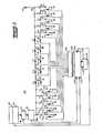
- Fig. 1illustrates the basic apparatus utilized to practice the method according to the invention.
- a radio frequency transmitter 10is of conventional design and, in this the preferred embodiment of the invention, has a nominal output impedance of 50 ohms. (not shown) may be associated with transmitter 10. In the conventional manner, the transmitter 10 may be tuned to any one of several channels by adjustment of an associated channel selector 12.
- the output from transmitter 10couples through a voltage standing wave ratio meter 14 and a phase meter 16 before being coupled to input terminal 18 of the antenna tuning elements, indicated generally at 20.
- Voltage standing wave ratio (VSWR) meter 14is of conventional design producing a signal at its output, 14a representative of the voltage standing wave ratio on the line.
- the standing wave ratiois an indicator of the relative match between sources or loads on opposite ends of the lines. Thus, for example, if the standing wave ratio is unity then a perfect match exists.
- Phase meter 16is also of conventional design and compares current and voltage on the line, producing a signal at its output 16a indicative of the phase of the current/ voltage relationship.
- the inductor/capacitor band 20is comprised of five input shunt capacitors Ci l -Ci S .
- the input shunt capacitors Ci l -Ci 5are arranged ascending binary incremented values such that, for example, the relative capacitance of the first capacitor C il is one, then that of the second capacitor Ci 2 is two, that of the third Ci 3 is four and so forth.
- Each input shunt capacitor Ci l -Ci 5is series coupled through relays 31-35 respectively, which relays, when activated, operate to connect the associated capacitor into the shunt circuit. Otherwise the input shunt capacitors are open circuited, and, thus, do not contribute to the antenna matching circuit.
- the series inductors L I -L 5have binary incremented values as with the input shunt capacitors.
- the relative value of the first inductor L 1is one, with inductors 2-5 having values two, four, eight and sixteen, respectively.
- a series of relays 41-45are coupled in shunt across each of the inductors. Upon activation of an appropriate relay the corresponding inductance is shorted, thereby removing the inductance from the circuit. In the absence of activation of its relay, an inductor will be included within the antenna matching circuit.
- Coupled to the output of the series inductors L l -L Sis a bank of five output shunt capacitors C 01 -C 05 As with the input shunt capacitors, the output shunt capacitors are arranged in binary increasing values. Also, a series of relays 51-55 are series coupled to the output shunt capacitors C 01 -C 05 , respectively, whereby an output shunt capacitor is corrected into the antenna matching circuit only upon activation of its relay.
- a node at the output shunt capacitorsdefines the output terminal 60 of the antenna matching circuit and is adapted for conventional coupling to an antenna, such as antenna 70.
- Microprocessor 100has inputs 101, 102 for receiving the provided outputs from the voltage standing wave ratio meter 14 and phase meter 16, respectively. Also provided as input 104 to microprocessor 100 is the output from the channel selector switch 11. Thus, the channel to which the transmitter 10 is tuned is an input to the microprocessor 100.
- microprocessor 100Associated with microprocessor 100 is a random access memory 110.
- the microprocessoris capable of addressing and storing information in the memory 110 via an address bus 112 and can also retrieve stored memory on a retrieval bus l14.
- the output from microprocessor 100is a plurality of lines 120 which feed to a plurality of relay drivers 122.
- the relay driversare provided with a plurality of 15 output lines, each of which couples to a predetermined one of the relays 31-35, 41-45 and 51-55 for controlling the status of the matching circuit.
- the micro- processorin response to the channel selector 12, voltage standing wave ratio meter 14 and phase meter 16, provides suitable outputs on its output lines 120 causing the relay drivers 122 to activate those input shunt capacitors, series inductors and output shunt capacitors suitable for matching the transmitter 10 to the antenna 70.
- the microprocessor control 100Once the microprocessor control 100 has determined that a particular circuit configuration is optimum for matching on a given channel, this information is loaded into memory 110 via address bus 112. Upon subsequent selection of that channel via channel selector 12, the information is retrieved from memory via retrieval bus 114 and the shunt capacitors and inductors are programmed accordingly.
- microprocessor 100may be comprised of any of numerous commercially available micro-process units. Any one of ordinary skill in this art could, having been given the following description of operation of the microprocessor 100, easily construct an operable embodiment of the invention.
- Fig. 2is a flow diagram illustrating the manner in which, according to the preferred embodiment of the invention, the microprocessor 100 is programmed.
- the systemis initialized.
- the antennais inductive and, thus, the microprocessor runs through the inductive routine.
- Table Idetails an example of the inductive routine and reference should be made to the Smith chart of Fig. 3 which illustrates the physical effects of this routine.
- the rotate inductor sequence 210is initiated.
- the series inductanceis increased by incrementing the series inductors L l -L 5 according to the truth table shown in Table I.
- this sequencebegins: L 1 , L 2 , L l + L 2 , L 3 , L 3 +L 2, L 3 + L 2 + L l , L 4 and so forth.
- the effect of increasing the series inductanceis to rotate the impedance seen at the input terminal 18 in a clockwise manner. This rotate-up sequence continues until the phase at the first terminal 18 of the antenna tuner is inductive, as is indicated by phase meter 16 to the microprocessor 100. This is illustrated as point F on Fig. 3.
- the microprocessorremoves the elemental value which resulted in the phase going inductive and inserts the next lower inductor. If this next lower element causes the phase to still be inductive point G, then it, also, is removed and the previous procedure repeats. If this next lower element results in the phase being capacitive point H, then it is left in the circuit; is not, the next lower value is added to the circult and is subjected to the same decision process as above. This routine continues until no more lower element values remain. This is illustrated in a sample tuning sequence in Table I with reference to Fig. 3 chart references F, G, H, I and J. The phase would be slightly capacitive at this point in the tuning algorithm.
- the microprocessorstores in memory that count for the largest inductor used during the rotate-up sequence. for the example of Table I, the highest inductor used was inductor L 5 .
- the series inductanceis increased by binary incrementing the series inductors L 1 -L 5 from their values at the conclusion of the rotate inductor sequence 210 until the phase is detected as going just inductive point 1.
- the output shunt capacitorsare decremented, also in a binary sequence, until the phase returns going just capacitive, point 2.
- the process of binary increasing the inductance and decreasing the capacitanceis continued via a feedback loop 245.
- the impedance seen at the antenna matching network first terminal 18sequentially increases in real value, as is indicated by arrow U in Fig. 3 and as indicated by reference numerals 1-10.
- the series inductance and output shunt capacitance valuesare stored in memory and the procedure is allowed to continue. If, on continuing in the inductive mode, a voltage standing wave ratio of 2:1 is reached, this is stored in memory, erasing the 4:1 stored settings. Finally, if a VSWR of 1.2:1 is reached, these values are stored in memory replacing those for 2:1 and the system stops since a match, within a suitable range, has been obtained. These values are then stored in memory to be used upon the transmitter being retuned to the same channel.
- the systemis activated to the capacitive routine, as indicated by block 260.
- the capacitive routine 260can also be activated if in the rotate inductor sequence 210 the system rotates through all of the inductors without detecting a phase change from capacitive to inductive, indicated via line 270.
- Table IIand corresponding Figs. 4a and 4b illustrate an example of operation in the capacitive mode.
- the antennainitially begins with a capacitive value P 2 , as shown on Fig. 4a.
- the first stepcomprises rotating the inductors, as shown by block 210. In this mode all input shunt capacitors and output shunt capacitors have been removed from the circuit by 260 in response to outputs 235 and 250 or 270.
- the inductorsare rotated until the impedance, as sensed by the phase meter 16, at the first terminal 18 goes inductive.
- the systemincrements the series inductance until the rotate sequence stops with the impedance at the first terminal 18 being slightly capacitive.
- the maximum count for the inductorsis stored, as indicated by block 220 and, as before in block 230, the series inductance is increased by binary increments until the impedance at the first terminal 18 goes slightly inductive, as is illustrated by point K on Figs. 4a and 4b.
- Fig. 4bis an enlarged section of arc 320 shown in Fig. 4a.
- the input shunt capacitorsare rotated up, as indicated by block 280. As shown in Table II, the rotation of the input shunt capacitors is accomplished by sequentially activating increasing value shunt capacitors until the phase as sensed at the first terminal 18 goes capacitive (point 0 in Fig. 4b).
- the elemental shunt capacitor value that caused the phase to go capacitiveis removed, and the next smaller valued capacitor is activated, causing the phase sensed to be inductive once again, point P.
- the next sequential lower value of shunt capacitanceis activated and the phase is monitored to detect if this elemental value caused the phase to become capacitive. If it does, point 0, then it is removed and the next lower sequential value is activated, point R, repeating the above process. If it does not cause the phase to become capacitive, then it is left in the circuit and the next lower sequential value is activated and subjected to the above process to determine if it should be left in or removed from the circuit depending on its effect upon the phase.
- the values of the shunt capacitors and the series inductorsmust be suitably selected such that the impedance seen at the first terminal 18 can be located on the real axis of the Smith chart at a value less than the nominal impedance of the transmitter, here, less than 50 ohms.
- the micro- processor controlled automatic antenna matching systemcan achieve proper impedance matching within a very short time interval.
- the instant algorithms givenprovide a practical means for incrementing and decrementing component values which takes into account parasitic effects such as the stray capacitance associated with the relays used to activate the components.
Landscapes
- Engineering & Computer Science (AREA)
- Computer Networks & Wireless Communication (AREA)
- Signal Processing (AREA)
- Transmitters (AREA)
Abstract
Description
- The present invention pertains to the radio frequency art and, more particularly, to a method for matching the output of a radio transmitter to an antenna.
- The prior art has developed numerous methods for the tuning of a radio frequency antenna to the output impedance of the transmitter, as this will assure maximum transmitted power. For fixed position, single frequency installations it is often possible to manually tune to the antenna only once without need for further concern. However, for applications wherein a transmitter is operable on any one of several channel frequencies and/or the antenna is subjected to varying conditions, such as in the case of marine applications, the maintenance of proper antenna tuning becomes very difficult.
- One approach to a tunable antenna coupling circuit is given in U.S. patent 3,906,405, which issued September 16, 1975 and is assigned to the same assignee as the instant application. In this approach, a series of inductors and capacitors are arranged between the transmitter and the antenna with relays operable to switch these components into or out of the circuit. The antenna is then manually tuned to the transmitter for each channel, with the optimum circuit configuration of the tuner being programmed via a diode matrix. Upon the transmitter being tuned to a giver: channel, the diodes activate the desired relays, thereby forming the proper matching circuit.
- While the above described prior art circuit constituted a significant advance in the antenna tuning art, it suffers from numerous disadvantages. Firstly, that system requires a manual set up of the antenna. Also, it does not automatically account for changes in the impedance of the antenna as may be caused by, for example, by spraying salt water in marine installations.
- Other attempts have been made to provide the semiautomatic tuning of an antenna. In one approach, manual tuning is accomplished to within a range, at which time a motor drives a variable capacitance to accomplish proper transmitter matching. Since the overall tuning range of this system is very small, the system provides limited utility.
- It is an object of this invention, therefore, to provide an improved method for matching the impedance of a transmitter to an antenna, which method may be accomplished by fully automatic means.
- It is a further object of the invention to provide the above described method which may be accomplished in economical manner and which requires short duration intervals for proper antenna matching.
- Briefly, according to the invention, the method for matching the nominal real impedance of a transmitter to an antenna comprises the steps of providing an input terminal, adapted for connection to the transmitter, and an output terminal adapted for connection to the antenna. A variable series inductance is provided between the first and second terminals. A variable shunt capacitance is coupled to a predetermined one of the first and second terminals. In the tuning operation, the inductance and capacitance are predeterminedly varied in a first mode, under the control of a microprocessor such that the impedance at the first terminal is substantially real having a value less than the nominal value. Then, the inductance and capacitance are varied in a second mode under the control of the microprocessor to increase the real part of the impedance at the first terminal until it is within a predetermined range from said nominal impedance, thereby establishing the impedance match.
- Fig. 1 is a schematic diagram illustrating the preferred embodiment of an antenna matching circuit according to the present invention;
- Fig. 2 is a flow diagram illustrative of operation of the inventive antenna matching circuit shown in the structure of Fig. 1;
- Fig. 3 is a Smith chart representation of operation of the instant antenna matching circuit for an inductive antenna;
- Fig. 4a is a Smith chart representation of operation of the inventive antenna matching circuit for a capacitive antenna; and
- Fig. 4b is an enlarged view of a section of the Smith chart shown in Fig. 4a.
- Fig. 1 illustrates the basic apparatus utilized to practice the method according to the invention. Here is shown a
radio frequency transmitter 10.Transmitter 10 is of conventional design and, in this the preferred embodiment of the invention, has a nominal output impedance of 50 ohms. (not shown) may be associated withtransmitter 10. In the conventional manner, thetransmitter 10 may be tuned to any one of several channels by adjustment of an associatedchannel selector 12. - The output from
transmitter 10 couples through a voltage standing wave ratio meter 14 and aphase meter 16 before being coupled to input terminal 18 of the antenna tuning elements, indicated generally at 20. - Voltage standing wave ratio (VSWR) meter 14 is of conventional design producing a signal at its output, 14a representative of the voltage standing wave ratio on the line. As is very well known in the radio frequency art, the standing wave ratio is an indicator of the relative match between sources or loads on opposite ends of the lines. Thus, for example, if the standing wave ratio is unity then a perfect match exists.
Phase meter 16 is also of conventional design and compares current and voltage on the line, producing a signal at its output 16a indicative of the phase of the current/ voltage relationship.- The inductor/
capacitor band 20 is comprised of five input shunt capacitors Cil-CiS. The input shunt capacitors Cil-Ci5 are arranged ascending binary incremented values such that, for example, the relative capacitance of the first capacitor Cil is one, then that of the second capacitor Ci2 is two, that of the third Ci3 is four and so forth. Each input shunt capacitor Cil-Ci5 is series coupled through relays 31-35 respectively, which relays, when activated, operate to connect the associated capacitor into the shunt circuit. Otherwise the input shunt capacitors are open circuited, and, thus, do not contribute to the antenna matching circuit. - Following the input shunt capacitors are a plurality of five series coupled inductors L1-L5. The series inductors LI-L5 have binary incremented values as with the input shunt capacitors. Thus the relative value of the first inductor L1 is one, with inductors 2-5 having values two, four, eight and sixteen, respectively. A series of relays 41-45 are coupled in shunt across each of the inductors. Upon activation of an appropriate relay the corresponding inductance is shorted, thereby removing the inductance from the circuit. In the absence of activation of its relay, an inductor will be included within the antenna matching circuit.
- Coupled to the output of the series inductors Ll-LS is a bank of five output shunt capacitors C01-C05 As with the input shunt capacitors, the output shunt capacitors are arranged in binary increasing values. Also, a series of relays 51-55 are series coupled to the output shunt capacitors C01-C05, respectively, whereby an output shunt capacitor is corrected into the antenna matching circuit only upon activation of its relay.
- A node at the output shunt capacitors defines the
output terminal 60 of the antenna matching circuit and is adapted for conventional coupling to an antenna, such as antenna 70. - The basic control of the system is provided by a
microprocessor 100.Microprocessor 100 hasinputs phase meter 16, respectively. Also provided asinput 104 tomicroprocessor 100 is the output from the channel selector switch 11. Thus, the channel to which thetransmitter 10 is tuned is an input to themicroprocessor 100. - Associated with
microprocessor 100 is arandom access memory 110. The microprocessor is capable of addressing and storing information in thememory 110 via anaddress bus 112 and can also retrieve stored memory on a retrieval bus l14. - The output from
microprocessor 100 is a plurality oflines 120 which feed to a plurality ofrelay drivers 122. The relay drivers are provided with a plurality of 15 output lines, each of which couples to a predetermined one of the relays 31-35, 41-45 and 51-55 for controlling the status of the matching circuit. - Thus, in response to the
channel selector 12, voltage standing wave ratio meter 14 andphase meter 16, the micro- processor provides suitable outputs on itsoutput lines 120 causing therelay drivers 122 to activate those input shunt capacitors, series inductors and output shunt capacitors suitable for matching thetransmitter 10 to the antenna 70. Once themicroprocessor control 100 has determined that a particular circuit configuration is optimum for matching on a given channel, this information is loaded intomemory 110 viaaddress bus 112. Upon subsequent selection of that channel viachannel selector 12, the information is retrieved from memory via retrieval bus 114 and the shunt capacitors and inductors are programmed accordingly. - It should be noted that the
microprocessor 100 may be comprised of any of numerous commercially available micro- processor units. Any one of ordinary skill in this art could, having been given the following description of operation of themicroprocessor 100, easily construct an operable embodiment of the invention. - Fig. 2 is a flow diagram illustrating the manner in which, according to the preferred embodiment of the invention, the
microprocessor 100 is programmed. - Firstly, according to block 200, the system is initialized. In the initialized condition, it is assumed that the antenna is inductive and, thus, the microprocessor runs through the inductive routine. Table I details an example of the inductive routine and reference should be made to the Smith chart of Fig. 3 which illustrates the physical effects of this routine.

- Thus, at initialize block 200 all of the relays 51-55 are activated, coupling the output shunt capacitors CO1-C05 into the circuit, and all of the relays 41-45 of the series inductors L1-L5 are activated thereby replacing them with a short circuit. In the inductive routine the input shunt capacitors Cil-Ci5 are not utilized, therefore their relays 31-35 remain inactive. In Table I, a "I" indicates that a component is in the circuit whereas a "0" indicates that it is not. A "C" indicates capacitive phase and an "I" indicates an inductive phase angle.
- Thus, initially all output shunt capacitors are in the circuit and all series inductors are shunted (electrically disabled) from the circuit. Thus, referring to Fig. 3, the impedance of the antenna, which initially is at point PI on the Smith chart is rotated clockwise to point A by the addition of the output shunt capacitors.
- Following the
initialize block 200 the rotateinductor sequence 210 is initiated. Here, the series inductance is increased by incrementing the series inductors Ll-L5 according to the truth table shown in Table I. Thus, this sequence begins: L1, L2, Ll+L2, L3,L3+L2, L3+L2+Ll, L4 and so forth. Referring to Fig. 3, the effect of increasing the series inductance is to rotate the impedance seen at the input terminal 18 in a clockwise manner. This rotate-up sequence continues until the phase at the first terminal 18 of the antenna tuner is inductive, as is indicated byphase meter 16 to themicroprocessor 100. This is illustrated as point F on Fig. 3. Once the phase is sensed as having gone inductive, the microprocessor removes the elemental value which resulted in the phase going inductive and inserts the next lower inductor. If this next lower element causes the phase to still be inductive point G, then it, also, is removed and the previous procedure repeats. If this next lower element results in the phase being capacitive point H, then it is left in the circuit; is not, the next lower value is added to the circult and is subjected to the same decision process as above. This routine continues until no more lower element values remain. This is illustrated in a sample tuning sequence in Table I with reference to Fig. 3 chart references F, G, H, I and J. The phase would be slightly capacitive at this point in the tuning algorithm. Atblock 220, the microprocessor stores in memory that count for the largest inductor used during the rotate-up sequence. for the example of Table I, the highest inductor used was inductor L5. - At block 230 the series inductance is increased by binary incrementing the series inductors L1-L5 from their values at the conclusion of the rotate
inductor sequence 210 until the phase is detected as going justinductive point 1. Following this, inblock 240, the output shunt capacitors are decremented, also in a binary sequence, until the phase returns going just capacitive,point 2. The process of binary increasing the inductance and decreasing the capacitance is continued via afeedback loop 245. In this manner, the impedance seen at the antenna matching network first terminal 18 sequentially increases in real value, as is indicated by arrowU in Fig. 3 and as indicated by reference numerals 1-10. If, during this sequence, the voltage standing wave ratio, as sensed bymicroprocessor 100 at itsinput 102, reaches 4:1, the series inductance and output shunt capacitance values are stored in memory and the procedure is allowed to continue. If, on continuing in the inductive mode, a voltage standing wave ratio of 2:1 is reached, this is stored in memory, erasing the 4:1 stored settings. Finally, if a VSWR of 1.2:1 is reached, these values are stored in memory replacing those for 2:1 and the system stops since a match, within a suitable range, has been obtained. These values are then stored in memory to be used upon the transmitter being retuned to the same channel. - If the system is incremented through all of the inductors, as illustrated by an
output line 235, or if it is decremented to zero all of the outputs shunt capacitors, indicated by anoutput line 250, the system is activated to the capacitive routine, as indicated byblock 260. The capacitive routine 260 can also be activated if in the rotateinductor sequence 210 the system rotates through all of the inductors without detecting a phase change from capacitive to inductive, indicated vialine 270. - Table II, and corresponding Figs. 4a and 4b illustrate an example of operation in the capacitive mode.
- Here, the antenna initially begins with a capacitive value P2, as shown on Fig. 4a. As before, the first step comprises rotating the inductors, as shown by
block 210. In this mode all input shunt capacitors and output shunt capacitors have been removed from the circuit by 260 in response tooutputs phase meter 16, at the first terminal 18 goes inductive. As before, the system increments the series inductance until the rotate sequence stops with the impedance at the first terminal 18 being slightly capacitive. - The maximum count for the inductors is stored, as indicated by
block 220 and, as before in block 230, the series inductance is increased by binary increments until the impedance at the first terminal 18 goes slightly inductive, as is illustrated by point K on Figs. 4a and 4b. Fig. 4b is an enlarged section ofarc 320 shown in Fig. 4a. Following this condition, in the capacitive routine, the input shunt capacitors are rotated up, as indicated byblock 280. As shown in Table II, the rotation of the input shunt capacitors is accomplished by sequentially activating increasing value shunt capacitors until the phase as sensed at the first terminal 18 goes capacitive (point 0 in Fig. 4b).
- Following the rotate shunt capacitance sequence, all input shunt capacitors are initialized to zero and the inductance is incremented by one binary count, as indicated by
block 290. Afeedback loop 295 returns to the capacitor rotatesequence 280 thus continuing the cycle point K'. By repetitions through this loop, (K" etc) the real part of the impedance at the first terminal 18 increases, indicated by the arrow U' of Fig. 4. As in the inductive mode, if voltage standing wave ratios of 4:1, 2:1 and/or 1.2:1 are achieved throughout the capacitive mode sequence, the values of inductors and capacitors are stored in memory to be subsequently recalled upon retuning to the same channel. - It should be noted that, whether operating in the capacitive or the inductive mode, the values of the shunt capacitors and the series inductors must be suitably selected such that the impedance seen at the first terminal 18 can be located on the real axis of the Smith chart at a value less than the nominal impedance of the transmitter, here, less than 50 ohms.
- By uslng the algorithms given hereinabove, the micro- processor controlled automatic antenna matching system can achieve proper impedance matching within a very short time interval. Also, the instant algorithms given provide a practical means for incrementing and decrementing component values which takes into account parasitic effects such as the stray capacitance associated with the relays used to activate the components.
- In summary, a fully automatic method for matching an antenna to a radio frequency transmitter has been described. The system not only achieves the desired antenna matching within a very short time, but it also requires the use of inexpensive, standard sensing devices, such as a phase meter and a voltage standing wave ratio meter.
- While a preferred embodiment of the invention has been described in detail, it should be apparent that many modifications and variations thereto are possible, all of which fall within the true spirit and scope of the invention.
- For example, whereas in the instant preferred embodiment of the invention five input shunt capacitors, five series inductors, and five output shunt capacitors are shown, it should be understood that in a given system configuration any number of circuit components may be employed, such as, in general, a number of N inductors and M capacitors, with N and M being selected in accordance with the system constraints.
- We claim:


Claims (11)
step c) comprises the steps of:
step d) comprises the steps of:
step e) comprises the steps of:
step f comprises the steps of:
step e) comprises the steps of:
step e) comprises the step of:
step f) further comprises the steps of:
step c) comprises the steps of:
L1' L2,L1+L2'L3,L3+L2'
L3+L2+Ll, L4, ... until the impedance at the first terminal becomes inductive with a real part being less than the real part of said nominal impedance;
step e) part iii) comprises the step of:
decreasing said series inductance from its value established in step e), part ii) by shunting out that inductor Lk whose value made the impedance at the first terminal inductive and successively activating those inductors of decreasing incremental binary value, Lk_l Lk-2 ..., until the impedance at said first terminal is capacitive.
step d) comprises the steps of:
step f) part i) comprises incrementing said induc- tors according to a binary sequence and wherein step f part ii) comprises decrementing the shunt capacitor according to a binary sequence.
step f) comprises the steps of:
step e) comprises the steps of:
step f) further comprises the steps of:
step c) further comprises the steps of:
L1, L2, L1+L2, L3, L3+L2,
L3+L2+Ll, L4 ... until the impedance at the first terminal becomes inductive;
step e) parti) comprises the step of:
step d) comprises the steps of:
step e) part ii) comprises the step of:
step f) comprises the steps of:
step e) further comprises the steps of:
Applications Claiming Priority (2)
| Application Number | Priority Date | Filing Date | Title |
|---|---|---|---|
| US909155 | 1978-05-24 | ||
| US05/909,155US4201960A (en) | 1978-05-24 | 1978-05-24 | Method for automatically matching a radio frequency transmitter to an antenna |
Publications (2)
| Publication Number | Publication Date |
|---|---|
| EP0005592A1true EP0005592A1 (en) | 1979-11-28 |
| EP0005592B1 EP0005592B1 (en) | 1984-04-11 |
Family
ID=25426720
Family Applications (1)
| Application Number | Title | Priority Date | Filing Date |
|---|---|---|---|
| EP79300707AExpiredEP0005592B1 (en) | 1978-05-24 | 1979-04-25 | A method of and an apparatus for automatically matching a radio frequency transmitter to an antenna |
Country Status (11)
| Country | Link |
|---|---|
| US (1) | US4201960A (en) |
| EP (1) | EP0005592B1 (en) |
| JP (1) | JPS5854685B2 (en) |
| AR (1) | AR223488A1 (en) |
| AU (1) | AU527683B2 (en) |
| BR (1) | BR7903232A (en) |
| CA (1) | CA1110707A (en) |
| DE (1) | DE2966885D1 (en) |
| DK (1) | DK157516C (en) |
| IL (1) | IL57185A (en) |
| ZA (1) | ZA791990B (en) |
Cited By (12)
| Publication number | Priority date | Publication date | Assignee | Title |
|---|---|---|---|---|
| EP0050918A3 (en)* | 1980-10-27 | 1983-06-15 | Texas Instruments Incorporated | Controlled antenna tuner |
| FR2573940A1 (en)* | 1984-11-23 | 1986-05-30 | Thomson Csf | Device for automatic adjustment of the matching cell of an antenna to its working frequency |
| EP0208984A1 (en)* | 1985-07-03 | 1987-01-21 | Siemens Aktiengesellschaft | Method for the automatic impedance matching of a transmitter with an antenna |
| EP0239219A3 (en)* | 1986-03-19 | 1989-04-05 | The Marconi Company Limited | High power systems |
| EP0663724A3 (en)* | 1993-06-28 | 1995-11-22 | Texas Instruments Deutschland | Automatic antenna tuning method. |
| EP1770665A1 (en)* | 1999-01-12 | 2007-04-04 | Soundcraft, Inc. | Auto-tuning scanning proximity reader |
| RU2308145C2 (en)* | 2005-10-17 | 2007-10-10 | Федеральное государственное унитарное предприятие Омский научно-исследовательский институт приборостроения | Antenna-matching device |
| EP1887705A2 (en) | 2006-08-07 | 2008-02-13 | Samsung Electronics Co., Ltd. | Radio frequency matching control apparatus and method for portable communication terminal |
| EP2151921A1 (en)* | 2008-08-07 | 2010-02-10 | Epcos AG | Dynamic impedance matching network and method for matching an impedance between a source and a load |
| EP1650875A3 (en)* | 2004-10-21 | 2011-11-23 | NEC Corporation | Automatic adjustment circuit, automatic adjustment method and portable terminal |
| CN102594286A (en)* | 2010-08-02 | 2012-07-18 | Lg伊诺特有限公司 | Apparatus and method for matching impedance using standing wave ratio information |
| EP2195880A4 (en)* | 2007-09-24 | 2013-02-13 | Cooper Tire & Rubber Co | Automatic antenna tuner system for rfid |
Families Citing this family (134)
| Publication number | Priority date | Publication date | Assignee | Title |
|---|---|---|---|---|
| US4335469A (en)* | 1980-06-18 | 1982-06-15 | Westinghouse Electric Corp. | Method and system for radiating RF power from a trailing wire antenna |
| DE3033407A1 (en)* | 1980-09-05 | 1982-04-22 | Robert Bosch Gmbh, 7000 Stuttgart | Two-way radio |
| JPS5851453B2 (en)* | 1980-09-29 | 1983-11-16 | 日本電信電話株式会社 | transmitting device |
| GB2100932B (en)* | 1981-06-18 | 1986-06-11 | Charles Edward Cooper | Antenna. |
| US4486722A (en)* | 1982-02-18 | 1984-12-04 | Rockwell International Corporation | Pin diode switched impedance matching network having diode driver circuits transparent to RF potential |
| US4485360A (en)* | 1982-07-16 | 1984-11-27 | Cincinnati Electronics Corporation | Apparatus for and method of impedance matching |
| JPS5950619A (en)* | 1982-09-16 | 1984-03-23 | Yaesu Musen Co Ltd | Automatic matching system of antenna circuit |
| US4513254A (en)* | 1983-05-16 | 1985-04-23 | International Business Machines Corporation | Integrated circuit filter with adjustable characteristics |
| JPS6018021A (en)* | 1983-07-09 | 1985-01-30 | Yaesu Musen Co Ltd | Antenna coupler |
| JPS6018022A (en)* | 1983-07-09 | 1985-01-30 | Yaesu Musen Co Ltd | Antenna coupler |
| JPS6080360U (en)* | 1983-11-04 | 1985-06-04 | 株式会社光電製作所 | Wireless direction finder with automatic selection of sense signal phase shift constant |
| FR2574597B1 (en)* | 1984-12-06 | 1986-12-26 | Commissariat Energie Atomique | HIGH FREQUENCY ANTENNA TUNING DEVICE |
| JPS61140640U (en)* | 1985-02-22 | 1986-08-30 | ||
| US4612669A (en)* | 1985-04-30 | 1986-09-16 | Rca Corporation | Antenna matching system |
| JPH0683081B2 (en)* | 1985-05-29 | 1994-10-19 | 日本無線株式会社 | Automatic alignment method |
| JPS6262624A (en)* | 1985-09-12 | 1987-03-19 | Yaesu Musen Co Ltd | Antenna matching device |
| US4682176A (en)* | 1986-03-12 | 1987-07-21 | The United States Of America As Represented By The Secretary Of The Air Force | Active matching transmit/receive module |
| DE3644476C2 (en)* | 1986-12-24 | 1995-11-02 | Daimler Benz Aerospace Ag | Impedance transformation method |
| DE3644477C2 (en)* | 1986-12-24 | 1995-11-02 | Daimler Benz Aerospace Ag | Impedance transformation method |
| DE3709169A1 (en)* | 1987-03-20 | 1988-09-29 | Standard Elektrik Lorenz Ag | Antenna coupler |
| US4855695A (en)* | 1988-04-29 | 1989-08-08 | E. I. Du Pont De Nemours & Company | Automated microwave tuning system for de-emulsifier systems |
| US5243356A (en)* | 1988-08-05 | 1993-09-07 | Seiko Epson Corporation | Antenna circuit and wrist radio instrument |
| US5128686A (en)* | 1989-01-23 | 1992-07-07 | Motorola, Inc. | Reactance buffered loop antenna and method for making the same |
| US5231355A (en)* | 1990-06-18 | 1993-07-27 | The Charles Machine Works, Inc. | Locator transmitter having an automatically tuned antenna |
| DE69220102T2 (en)* | 1991-02-19 | 1997-09-25 | Nippon Electric Co | Pager |
| ES2097881T3 (en)* | 1991-09-04 | 1997-04-16 | Nec Corp | RADIO TRANSCEIVER. |
| US5424691A (en)* | 1994-02-03 | 1995-06-13 | Sadinsky; Samuel | Apparatus and method for electronically controlled admittance matching network |
| US5495212A (en)* | 1994-12-19 | 1996-02-27 | Bh Electronics, Inc. | Coupling device connecting an unbalanced signal line to a balanced signal line |
| US6150896A (en)* | 1994-12-19 | 2000-11-21 | Bh Electronics, Inc. | Coupling device connecting an unbalanced signal line to a balanced signal line |
| DE59602405D1 (en)* | 1995-09-15 | 1999-08-12 | Siemens Ag | RADIO WITH MULTIPLE FREQUENCY RANGES |
| US5631611A (en)* | 1996-06-18 | 1997-05-20 | Nautel Limited | Automatic matching and tuning network |
| US6362737B1 (en) | 1998-06-02 | 2002-03-26 | Rf Code, Inc. | Object Identification system with adaptive transceivers and methods of operation |
| DE19644339C1 (en)* | 1996-10-25 | 1998-06-10 | Bosch Gmbh Robert | Device for transforming an antenna impedance |
| US8779322B2 (en) | 1997-06-26 | 2014-07-15 | Mks Instruments Inc. | Method and apparatus for processing metal bearing gases |
| US7569790B2 (en)* | 1997-06-26 | 2009-08-04 | Mks Instruments, Inc. | Method and apparatus for processing metal bearing gases |
| US6150628A (en)* | 1997-06-26 | 2000-11-21 | Applied Science And Technology, Inc. | Toroidal low-field reactive gas source |
| US6924455B1 (en) | 1997-06-26 | 2005-08-02 | Applied Science & Technology, Inc. | Integrated plasma chamber and inductively-coupled toroidal plasma source |
| US7166816B1 (en)* | 1997-06-26 | 2007-01-23 | Mks Instruments, Inc. | Inductively-coupled torodial plasma source |
| US6351215B2 (en) | 1998-06-02 | 2002-02-26 | Rf Code, Inc. | Monitoring antenna system |
| US6307468B1 (en) | 1999-07-20 | 2001-10-23 | Avid Identification Systems, Inc. | Impedance matching network and multidimensional electromagnetic field coil for a transponder interrogator |
| JP4652499B2 (en)* | 1999-07-29 | 2011-03-16 | 株式会社ダイヘン | Impedance automatic matching method and matching device |
| US6424232B1 (en)* | 1999-11-30 | 2002-07-23 | Advanced Energy's Voorhees Operations | Method and apparatus for matching a variable load impedance with an RF power generator impedance |
| AU2001274896A1 (en) | 2000-05-22 | 2001-12-03 | Avery Dennison Corporation | Trackable files and systems for using the same |
| US7865154B2 (en)* | 2000-07-20 | 2011-01-04 | Paratek Microwave, Inc. | Tunable microwave devices with auto-adjusting matching circuit |
| US8744384B2 (en) | 2000-07-20 | 2014-06-03 | Blackberry Limited | Tunable microwave devices with auto-adjusting matching circuit |
| US8064188B2 (en) | 2000-07-20 | 2011-11-22 | Paratek Microwave, Inc. | Optimized thin film capacitors |
| EP1301960A1 (en) | 2000-07-20 | 2003-04-16 | Paratek Microwave, Inc. | Tunable microwave devices with auto-adjusting matching circuit |
| US6887339B1 (en) | 2000-09-20 | 2005-05-03 | Applied Science And Technology, Inc. | RF power supply with integrated matching network |
| EP1365507A1 (en)* | 2002-05-22 | 2003-11-26 | Lucent Technologies Inc. | Universal tuning and matching device |
| EP1542311A4 (en)* | 2002-11-01 | 2011-01-05 | Fujitsu Ltd | DEVICE AND METHOD FOR CONTROLLING |
| DE10353613A1 (en)* | 2003-11-17 | 2005-06-23 | Feig Electronic Gmbh | Adjusting/controlling device for a radio frequency identification antenna has an antenna loop and an antenna adapter unit |
| EP1538557B1 (en)* | 2003-12-05 | 2013-02-13 | STMicroelectronics S.A. | Resistive and capacitive modulation in an electromagnetic transponder |
| SE0400801D0 (en) | 2004-03-26 | 2004-03-26 | Asperation Oy | Antenna device |
| GB2420923B (en)* | 2004-11-15 | 2007-05-02 | Motorola Inc | Amplifier circuit |
| US20070004344A1 (en)* | 2005-06-29 | 2007-01-04 | Degroot Robert J | Wireless device and system for discriminating different operating environments |
| FI20055420A0 (en)* | 2005-07-25 | 2005-07-25 | Lk Products Oy | Adjustable multi-band antenna |
| FI119009B (en) | 2005-10-03 | 2008-06-13 | Pulse Finland Oy | Multiple-band antenna |
| FI118782B (en) | 2005-10-14 | 2008-03-14 | Pulse Finland Oy | Adjustable antenna |
| US9406444B2 (en) | 2005-11-14 | 2016-08-02 | Blackberry Limited | Thin film capacitors |
| KR100752280B1 (en)* | 2005-12-14 | 2007-08-28 | 삼성전자주식회사 | Device for matching frequency of antenna automatically in wireless terminal |
| US7711337B2 (en) | 2006-01-14 | 2010-05-04 | Paratek Microwave, Inc. | Adaptive impedance matching module (AIMM) control architectures |
| US8125399B2 (en) | 2006-01-14 | 2012-02-28 | Paratek Microwave, Inc. | Adaptively tunable antennas incorporating an external probe to monitor radiated power |
| US8325097B2 (en) | 2006-01-14 | 2012-12-04 | Research In Motion Rf, Inc. | Adaptively tunable antennas and method of operation therefore |
| CN101401302A (en)* | 2006-03-09 | 2009-04-01 | Nxp股份有限公司 | Radio receiver |
| US8618990B2 (en) | 2011-04-13 | 2013-12-31 | Pulse Finland Oy | Wideband antenna and methods |
| US8081940B2 (en)* | 2006-09-29 | 2011-12-20 | Broadcom Corporation | Method and system for dynamically tuning and calibrating an antenna using an on-chip digitally controlled array of capacitors |
| US7535312B2 (en)* | 2006-11-08 | 2009-05-19 | Paratek Microwave, Inc. | Adaptive impedance matching apparatus, system and method with improved dynamic range |
| US8299867B2 (en)* | 2006-11-08 | 2012-10-30 | Research In Motion Rf, Inc. | Adaptive impedance matching module |
| US7714676B2 (en)* | 2006-11-08 | 2010-05-11 | Paratek Microwave, Inc. | Adaptive impedance matching apparatus, system and method |
| US7813777B2 (en)* | 2006-12-12 | 2010-10-12 | Paratek Microwave, Inc. | Antenna tuner with zero volts impedance fold back |
| US9130274B1 (en)* | 2007-03-22 | 2015-09-08 | Board Of Education, State Of Rhode Island And Providence Plantations | Systems and methods for providing distributed load monopole antenna systems |
| FI20075269A0 (en) | 2007-04-19 | 2007-04-19 | Pulse Finland Oy | Method and arrangement for antenna matching |
| US7917104B2 (en)* | 2007-04-23 | 2011-03-29 | Paratek Microwave, Inc. | Techniques for improved adaptive impedance matching |
| US8213886B2 (en) | 2007-05-07 | 2012-07-03 | Paratek Microwave, Inc. | Hybrid techniques for antenna retuning utilizing transmit and receive power information |
| US7973645B1 (en)* | 2007-05-25 | 2011-07-05 | Impinj, Inc. | RFID reader devices and methods thereof |
| FI120427B (en) | 2007-08-30 | 2009-10-15 | Pulse Finland Oy | Adjustable multiband antenna |
| US7991363B2 (en) | 2007-11-14 | 2011-08-02 | Paratek Microwave, Inc. | Tuning matching circuits for transmitter and receiver bands as a function of transmitter metrics |
| NO328610B1 (en) | 2008-05-08 | 2010-03-29 | Comrod As | Radio frequency signal transmission unit and method of alternatively using an electric antenna or magnetic antenna with a classical antenna tuner |
| US8072285B2 (en) | 2008-09-24 | 2011-12-06 | Paratek Microwave, Inc. | Methods for tuning an adaptive impedance matching network with a look-up table |
| US8067858B2 (en)* | 2008-10-14 | 2011-11-29 | Paratek Microwave, Inc. | Low-distortion voltage variable capacitor assemblies |
| US8072272B2 (en)* | 2009-08-19 | 2011-12-06 | Qualcomm, Incorporated | Digital tunable inter-stage matching circuit |
| US8472888B2 (en) | 2009-08-25 | 2013-06-25 | Research In Motion Rf, Inc. | Method and apparatus for calibrating a communication device |
| US9026062B2 (en) | 2009-10-10 | 2015-05-05 | Blackberry Limited | Method and apparatus for managing operations of a communication device |
| US8204446B2 (en)* | 2009-10-29 | 2012-06-19 | Motorola Mobility, Inc. | Adaptive antenna tuning systems and methods |
| FI20096134A0 (en) | 2009-11-03 | 2009-11-03 | Pulse Finland Oy | Adjustable antenna |
| FI20096251A0 (en) | 2009-11-27 | 2009-11-27 | Pulse Finland Oy | MIMO antenna |
| DE102010028991B4 (en)* | 2009-12-03 | 2014-12-24 | Fraunhofer-Gesellschaft zur Förderung der angewandten Forschung e.V. | Passive transponder for an RFID system and method for transmitting data to / from a data source of such a passive transponder |
| US8847833B2 (en) | 2009-12-29 | 2014-09-30 | Pulse Finland Oy | Loop resonator apparatus and methods for enhanced field control |
| FI20105158L (en) | 2010-02-18 | 2011-08-19 | Pulse Finland Oy | ANTENNA EQUIPPED WITH SHELL RADIATOR |
| US8803631B2 (en) | 2010-03-22 | 2014-08-12 | Blackberry Limited | Method and apparatus for adapting a variable impedance network |
| US8754826B2 (en)* | 2010-04-15 | 2014-06-17 | Sony Corporation | Antenna device and radio communication apparatus |
| JP5901612B2 (en) | 2010-04-20 | 2016-04-13 | ブラックベリー リミテッド | Method and apparatus for managing interference in a communication device |
| US9406998B2 (en) | 2010-04-21 | 2016-08-02 | Pulse Finland Oy | Distributed multiband antenna and methods |
| JP5489225B2 (en)* | 2010-06-24 | 2014-05-14 | 株式会社ネットコムセック | Antenna matching circuit |
| US9379454B2 (en) | 2010-11-08 | 2016-06-28 | Blackberry Limited | Method and apparatus for tuning antennas in a communication device |
| FI20115072A0 (en) | 2011-01-25 | 2011-01-25 | Pulse Finland Oy | Multi-resonance antenna, antenna module and radio unit |
| US8648752B2 (en) | 2011-02-11 | 2014-02-11 | Pulse Finland Oy | Chassis-excited antenna apparatus and methods |
| US9673507B2 (en) | 2011-02-11 | 2017-06-06 | Pulse Finland Oy | Chassis-excited antenna apparatus and methods |
| US8712340B2 (en) | 2011-02-18 | 2014-04-29 | Blackberry Limited | Method and apparatus for radio antenna frequency tuning |
| US8655286B2 (en) | 2011-02-25 | 2014-02-18 | Blackberry Limited | Method and apparatus for tuning a communication device |
| US8594584B2 (en) | 2011-05-16 | 2013-11-26 | Blackberry Limited | Method and apparatus for tuning a communication device |
| US8626083B2 (en) | 2011-05-16 | 2014-01-07 | Blackberry Limited | Method and apparatus for tuning a communication device |
| JP2013005614A (en)* | 2011-06-17 | 2013-01-07 | Toyota Motor Corp | Power transmission equipment, power incoming equipment, vehicle, and non-contact power supply system |
| US8866689B2 (en) | 2011-07-07 | 2014-10-21 | Pulse Finland Oy | Multi-band antenna and methods for long term evolution wireless system |
| US9450291B2 (en) | 2011-07-25 | 2016-09-20 | Pulse Finland Oy | Multiband slot loop antenna apparatus and methods |
| EP2740221B1 (en) | 2011-08-05 | 2019-06-26 | BlackBerry Limited | Method and apparatus for band tuning in a communication device |
| US8712355B2 (en) | 2011-08-30 | 2014-04-29 | Motorola Mobility Llc | Antenna tuning on an impedance trajectory |
| US9123990B2 (en) | 2011-10-07 | 2015-09-01 | Pulse Finland Oy | Multi-feed antenna apparatus and methods |
| US9531058B2 (en) | 2011-12-20 | 2016-12-27 | Pulse Finland Oy | Loosely-coupled radio antenna apparatus and methods |
| US9484619B2 (en) | 2011-12-21 | 2016-11-01 | Pulse Finland Oy | Switchable diversity antenna apparatus and methods |
| US8988296B2 (en) | 2012-04-04 | 2015-03-24 | Pulse Finland Oy | Compact polarized antenna and methods |
| US8948889B2 (en) | 2012-06-01 | 2015-02-03 | Blackberry Limited | Methods and apparatus for tuning circuit components of a communication device |
| US9853363B2 (en) | 2012-07-06 | 2017-12-26 | Blackberry Limited | Methods and apparatus to control mutual coupling between antennas |
| US9246223B2 (en) | 2012-07-17 | 2016-01-26 | Blackberry Limited | Antenna tuning for multiband operation |
| US9413066B2 (en) | 2012-07-19 | 2016-08-09 | Blackberry Limited | Method and apparatus for beam forming and antenna tuning in a communication device |
| US9350405B2 (en) | 2012-07-19 | 2016-05-24 | Blackberry Limited | Method and apparatus for antenna tuning and power consumption management in a communication device |
| US9362891B2 (en) | 2012-07-26 | 2016-06-07 | Blackberry Limited | Methods and apparatus for tuning a communication device |
| US9979078B2 (en) | 2012-10-25 | 2018-05-22 | Pulse Finland Oy | Modular cell antenna apparatus and methods |
| US10069209B2 (en) | 2012-11-06 | 2018-09-04 | Pulse Finland Oy | Capacitively coupled antenna apparatus and methods |
| US8725214B1 (en)* | 2012-11-30 | 2014-05-13 | The United States Of America, As Represented By The Secretary Of The Navy | Method of tuning a frequency agile electrically small tactical AM broadcast band antenna system |
| US10404295B2 (en) | 2012-12-21 | 2019-09-03 | Blackberry Limited | Method and apparatus for adjusting the timing of radio antenna tuning |
| US9374113B2 (en) | 2012-12-21 | 2016-06-21 | Blackberry Limited | Method and apparatus for adjusting the timing of radio antenna tuning |
| US9647338B2 (en) | 2013-03-11 | 2017-05-09 | Pulse Finland Oy | Coupled antenna structure and methods |
| US10079428B2 (en) | 2013-03-11 | 2018-09-18 | Pulse Finland Oy | Coupled antenna structure and methods |
| US9634383B2 (en) | 2013-06-26 | 2017-04-25 | Pulse Finland Oy | Galvanically separated non-interacting antenna sector apparatus and methods |
| US9680212B2 (en) | 2013-11-20 | 2017-06-13 | Pulse Finland Oy | Capacitive grounding methods and apparatus for mobile devices |
| US9590308B2 (en) | 2013-12-03 | 2017-03-07 | Pulse Electronics, Inc. | Reduced surface area antenna apparatus and mobile communications devices incorporating the same |
| US9350081B2 (en) | 2014-01-14 | 2016-05-24 | Pulse Finland Oy | Switchable multi-radiator high band antenna apparatus |
| US9729190B2 (en) | 2014-01-17 | 2017-08-08 | Qualcomm Incorporated | Switchable antenna array |
| US9948002B2 (en) | 2014-08-26 | 2018-04-17 | Pulse Finland Oy | Antenna apparatus with an integrated proximity sensor and methods |
| US9973228B2 (en) | 2014-08-26 | 2018-05-15 | Pulse Finland Oy | Antenna apparatus with an integrated proximity sensor and methods |
| US9722308B2 (en) | 2014-08-28 | 2017-08-01 | Pulse Finland Oy | Low passive intermodulation distributed antenna system for multiple-input multiple-output systems and methods of use |
| US9438319B2 (en) | 2014-12-16 | 2016-09-06 | Blackberry Limited | Method and apparatus for antenna selection |
| US9906260B2 (en) | 2015-07-30 | 2018-02-27 | Pulse Finland Oy | Sensor-based closed loop antenna swapping apparatus and methods |
Citations (8)
| Publication number | Priority date | Publication date | Assignee | Title |
|---|---|---|---|---|
| US3509500A (en)* | 1966-12-05 | 1970-04-28 | Avco Corp | Automatic digital tuning apparatus |
| DE1921566A1 (en)* | 1969-04-28 | 1970-12-03 | Walter Tilleke | Pressure beam for grinding machines |
| FR2040274A1 (en)* | 1969-04-26 | 1971-01-22 | Int Standard Electric Corp | |
| US3675130A (en)* | 1970-09-18 | 1972-07-04 | Int Standard Electric Corp | A circuit arrangement for effecting a tuning of a transceiver by means of a mangetic core memory |
| CH527517A (en)* | 1970-07-17 | 1972-08-31 | Zellweger Uster Ag | Method and device for automatic impedance matching, in particular for matching an antenna to a given impedance |
| US3778731A (en)* | 1972-06-05 | 1973-12-11 | Cincinnati Electronics Corp | Tuning method for t-network couplers |
| FR2344179A1 (en)* | 1976-03-09 | 1977-10-07 | Thomson Csf | RADIOELECTRIC DEVICE AND TRANSCEIVER EQUIPPED WITH SUCH A DEVICE |
| FR2346901A1 (en)* | 1976-04-02 | 1977-10-28 | Alliance Tech Ind | Radio wave aerial tuning circuit - compares increments of inductance and capacitance with known impedance in discriminating circuit |
Family Cites Families (4)
| Publication number | Priority date | Publication date | Assignee | Title |
|---|---|---|---|---|
| US2745067A (en)* | 1951-06-28 | 1956-05-08 | True Virgil | Automatic impedance matching apparatus |
| US3794941A (en)* | 1972-05-08 | 1974-02-26 | Hughes Aircraft Co | Automatic antenna impedance tuner including digital control circuits |
| GB1524965A (en)* | 1974-10-15 | 1978-09-13 | Cincinnati Electronics Corp | Technique for automatic matching of high q-loads |
| US4112395A (en)* | 1977-06-10 | 1978-09-05 | Cincinnati Electronics Corp. | Method of and apparatus for matching a load circuit to a drive circuit |
- 1978
- 1978-05-24USUS05/909,155patent/US4201960A/ennot_activeExpired - Lifetime
- 1979
- 1979-04-25DEDE7979300707Tpatent/DE2966885D1/ennot_activeExpired
- 1979-04-25CACA326,326Apatent/CA1110707A/ennot_activeExpired
- 1979-04-25ZAZA791990Apatent/ZA791990B/enunknown
- 1979-04-25EPEP79300707Apatent/EP0005592B1/ennot_activeExpired
- 1979-04-26AUAU46492/79Apatent/AU527683B2/ennot_activeExpired
- 1979-04-30ILIL57185Apatent/IL57185A/enunknown
- 1979-05-16JPJP54060235Apatent/JPS5854685B2/ennot_activeExpired
- 1979-05-18ARAR276574Apatent/AR223488A1/enactive
- 1979-05-23BRBR7903232Apatent/BR7903232A/enunknown
- 1979-05-23DKDK211679Apatent/DK157516C/ennot_activeIP Right Cessation
Patent Citations (9)
| Publication number | Priority date | Publication date | Assignee | Title |
|---|---|---|---|---|
| US3509500A (en)* | 1966-12-05 | 1970-04-28 | Avco Corp | Automatic digital tuning apparatus |
| FR2040274A1 (en)* | 1969-04-26 | 1971-01-22 | Int Standard Electric Corp | |
| DE1921566A1 (en)* | 1969-04-28 | 1970-12-03 | Walter Tilleke | Pressure beam for grinding machines |
| CH527517A (en)* | 1970-07-17 | 1972-08-31 | Zellweger Uster Ag | Method and device for automatic impedance matching, in particular for matching an antenna to a given impedance |
| DE2220749A1 (en)* | 1970-07-17 | 1973-11-15 | Zellweger Uster Ag | METHOD AND DEVICE FOR AUTOMATIC IMPEDANCE ADAPTATION, IN PARTICULAR FOR ADAPTING AN ANTENNA TO A GIVEN IMPEDANCE |
| US3675130A (en)* | 1970-09-18 | 1972-07-04 | Int Standard Electric Corp | A circuit arrangement for effecting a tuning of a transceiver by means of a mangetic core memory |
| US3778731A (en)* | 1972-06-05 | 1973-12-11 | Cincinnati Electronics Corp | Tuning method for t-network couplers |
| FR2344179A1 (en)* | 1976-03-09 | 1977-10-07 | Thomson Csf | RADIOELECTRIC DEVICE AND TRANSCEIVER EQUIPPED WITH SUCH A DEVICE |
| FR2346901A1 (en)* | 1976-04-02 | 1977-10-28 | Alliance Tech Ind | Radio wave aerial tuning circuit - compares increments of inductance and capacitance with known impedance in discriminating circuit |
Non-Patent Citations (1)
| Title |
|---|
| FUNKSCHAU, Volume 47, January 31, 1975, No. 3 Munich (DE) N. ROHDE: "Die Planung von leichten, tragbaren KW-Sendeemp-fangern", page 39-41 * figure 5; page 41, right-hand column, lines 12-23 ** |
Cited By (17)
| Publication number | Priority date | Publication date | Assignee | Title |
|---|---|---|---|---|
| EP0050918A3 (en)* | 1980-10-27 | 1983-06-15 | Texas Instruments Incorporated | Controlled antenna tuner |
| FR2573940A1 (en)* | 1984-11-23 | 1986-05-30 | Thomson Csf | Device for automatic adjustment of the matching cell of an antenna to its working frequency |
| EP0208984A1 (en)* | 1985-07-03 | 1987-01-21 | Siemens Aktiengesellschaft | Method for the automatic impedance matching of a transmitter with an antenna |
| EP0239219A3 (en)* | 1986-03-19 | 1989-04-05 | The Marconi Company Limited | High power systems |
| EP0663724A3 (en)* | 1993-06-28 | 1995-11-22 | Texas Instruments Deutschland | Automatic antenna tuning method. |
| EP1770665A1 (en)* | 1999-01-12 | 2007-04-04 | Soundcraft, Inc. | Auto-tuning scanning proximity reader |
| EP1650875A3 (en)* | 2004-10-21 | 2011-11-23 | NEC Corporation | Automatic adjustment circuit, automatic adjustment method and portable terminal |
| RU2308145C2 (en)* | 2005-10-17 | 2007-10-10 | Федеральное государственное унитарное предприятие Омский научно-исследовательский институт приборостроения | Antenna-matching device |
| EP1887705A2 (en) | 2006-08-07 | 2008-02-13 | Samsung Electronics Co., Ltd. | Radio frequency matching control apparatus and method for portable communication terminal |
| EP1887705A3 (en)* | 2006-08-07 | 2011-09-14 | Samsung Electronics Co., Ltd. | Radio frequency matching control apparatus and method for portable communication terminal |
| EP2195880A4 (en)* | 2007-09-24 | 2013-02-13 | Cooper Tire & Rubber Co | Automatic antenna tuner system for rfid |
| EP2151921A1 (en)* | 2008-08-07 | 2010-02-10 | Epcos AG | Dynamic impedance matching network and method for matching an impedance between a source and a load |
| WO2010015550A1 (en)* | 2008-08-07 | 2010-02-11 | Epcos Ag | Dynamic impedance matching network and method for matching an impedance between a source and a load |
| US8542078B2 (en) | 2008-08-07 | 2013-09-24 | Epcos Ag | Dynamic impedance matching network and method for matching an impedance between a source and a load |
| CN102594286A (en)* | 2010-08-02 | 2012-07-18 | Lg伊诺特有限公司 | Apparatus and method for matching impedance using standing wave ratio information |
| EP2416494A3 (en)* | 2010-08-02 | 2013-04-03 | LG Innotek Co., Ltd. | Apparatus and method for matching impedance using standing wave ratio information |
| US9166551B2 (en) | 2010-08-02 | 2015-10-20 | Lg Innotek Co., Ltd. | Apparatus and method for matching impedance using standing wave ratio information |
Also Published As
| Publication number | Publication date |
|---|---|
| AU527683B2 (en) | 1983-03-17 |
| CA1110707A (en) | 1981-10-13 |
| BR7903232A (en) | 1979-12-11 |
| DK157516C (en) | 1990-06-05 |
| IL57185A (en) | 1981-10-30 |
| AU4649279A (en) | 1979-11-29 |
| US4201960A (en) | 1980-05-06 |
| DE2966885D1 (en) | 1984-05-17 |
| DK157516B (en) | 1990-01-15 |
| EP0005592B1 (en) | 1984-04-11 |
| AR223488A1 (en) | 1981-08-31 |
| DK211679A (en) | 1979-11-25 |
| JPS5854685B2 (en) | 1983-12-06 |
| JPS54153507A (en) | 1979-12-03 |
| IL57185A0 (en) | 1979-07-25 |
| ZA791990B (en) | 1980-05-28 |
Similar Documents
| Publication | Publication Date | Title |
|---|---|---|
| EP0005592A1 (en) | A method of and an apparatus for automatically matching a radio frequency transmitter to an antenna | |
| US3794941A (en) | Automatic antenna impedance tuner including digital control circuits | |
| US4799066A (en) | Impedance matching arrangement | |
| CA1167577A (en) | Multiplexing arrangement for a plurality of voltage controlled filters | |
| USRE39051E1 (en) | Fuzzy logic tuning of RF matching network | |
| US6424232B1 (en) | Method and apparatus for matching a variable load impedance with an RF power generator impedance | |
| US3160832A (en) | Automatic coupling and impedance matching network | |
| US4263539A (en) | Automatic antenna positioning apparatus | |
| US4352202A (en) | Combined remote control for wireless communication equipment and associated antenna | |
| EP0428229A1 (en) | tunable high-frequency antenna | |
| US20110273354A1 (en) | Transfer Unit for Radio Frequency Signals and Method for Alternatively Using an Electrical Antenna or a Magnetic Antenna with a Classic Antenna Tuner | |
| EP0147518B1 (en) | Aligning method for a multistage selective amplifier and circuit arrangement for carrying it out | |
| EP0239219A2 (en) | High power systems | |
| US3293572A (en) | Electrically variable resonant circuit controlled by the frequency of a separate pilot input signal | |
| US4692724A (en) | High power tunable filter | |
| US3942122A (en) | Multiband tuner control system | |
| US3987400A (en) | Multiband scanning radio receiver | |
| EP1073199B1 (en) | Television tuner that generates no interfering signal | |
| US4325030A (en) | Frequency discriminator for signal receiver of telecommunication system | |
| US2502396A (en) | Automatic control of radio transmitters and the like | |
| DE4335091C2 (en) | Programmable electronic tuner for television antennas | |
| US2804544A (en) | Two band long line superheterodyne tuner using two modes of resonance for oscillatorline | |
| US1658718A (en) | Tuned circuits of wireless apparatus | |
| US4352206A (en) | Comparison arrangement for a digital tuning system | |
| JPS6316192Y2 (en) |
Legal Events
| Date | Code | Title | Description |
|---|---|---|---|
| PUAI | Public reference made under article 153(3) epc to a published international application that has entered the european phase | Free format text:ORIGINAL CODE: 0009012 | |
| AK | Designated contracting states | Designated state(s):CH DE FR GB NL SE | |
| 17P | Request for examination filed | ||
| GRAA | (expected) grant | Free format text:ORIGINAL CODE: 0009210 | |
| AK | Designated contracting states | Designated state(s):CH DE FR GB NL SE | |
| REF | Corresponds to: | Ref document number:2966885 Country of ref document:DE Date of ref document:19840517 | |
| ET | Fr: translation filed | ||
| PLBE | No opposition filed within time limit | Free format text:ORIGINAL CODE: 0009261 | |
| STAA | Information on the status of an ep patent application or granted ep patent | Free format text:STATUS: NO OPPOSITION FILED WITHIN TIME LIMIT | |
| 26N | No opposition filed | ||
| PGFP | Annual fee paid to national office [announced via postgrant information from national office to epo] | Ref country code:GB Payment date:19900402 Year of fee payment:12 | |
| PGFP | Annual fee paid to national office [announced via postgrant information from national office to epo] | Ref country code:FR Payment date:19900423 Year of fee payment:12 | |
| PGFP | Annual fee paid to national office [announced via postgrant information from national office to epo] | Ref country code:DE Payment date:19900424 Year of fee payment:12 | |
| PGFP | Annual fee paid to national office [announced via postgrant information from national office to epo] | Ref country code:NL Payment date:19900430 Year of fee payment:12 | |
| PGFP | Annual fee paid to national office [announced via postgrant information from national office to epo] | Ref country code:CH Payment date:19900507 Year of fee payment:12 | |
| PG25 | Lapsed in a contracting state [announced via postgrant information from national office to epo] | Ref country code:GB Effective date:19910425 | |
| PGFP | Annual fee paid to national office [announced via postgrant information from national office to epo] | Ref country code:SE Payment date:19910425 Year of fee payment:13 | |
| PG25 | Lapsed in a contracting state [announced via postgrant information from national office to epo] | Ref country code:CH Effective date:19910430 | |
| PG25 | Lapsed in a contracting state [announced via postgrant information from national office to epo] | Ref country code:NL Effective date:19911101 | |
| NLV4 | Nl: lapsed or anulled due to non-payment of the annual fee | ||
| PG25 | Lapsed in a contracting state [announced via postgrant information from national office to epo] | Ref country code:FR Effective date:19911230 | |
| REG | Reference to a national code | Ref country code:CH Ref legal event code:PL | |
| GBPC | Gb: european patent ceased through non-payment of renewal fee | ||
| PG25 | Lapsed in a contracting state [announced via postgrant information from national office to epo] | Ref country code:DE Effective date:19920201 | |
| REG | Reference to a national code | Ref country code:FR Ref legal event code:ST | |
| PG25 | Lapsed in a contracting state [announced via postgrant information from national office to epo] | Ref country code:SE Effective date:19920426 | |
| EUG | Se: european patent has lapsed | Ref document number:79300707.1 Effective date:19921108 |