EP0001885B1 - Electrical connector assembly including latching means - Google Patents
Electrical connector assembly including latching meansDownload PDFInfo
- Publication number
- EP0001885B1 EP0001885B1EP78300430AEP78300430AEP0001885B1EP 0001885 B1EP0001885 B1EP 0001885B1EP 78300430 AEP78300430 AEP 78300430AEP 78300430 AEP78300430 AEP 78300430AEP 0001885 B1EP0001885 B1EP 0001885B1
- Authority
- EP
- European Patent Office
- Prior art keywords
- housing
- connector
- connectors
- spring member
- projections
- Prior art date
- Legal status (The legal status is an assumption and is not a legal conclusion. Google has not performed a legal analysis and makes no representation as to the accuracy of the status listed.)
- Expired
Links
- 230000013011matingEffects0.000claimsdescription11
- 239000004020conductorSubstances0.000description7
- 230000000712assemblyEffects0.000description1
- 238000000429assemblyMethods0.000description1
- 230000037431insertionEffects0.000description1
- 238000003780insertionMethods0.000description1
- 239000000463materialSubstances0.000description1
- 239000002184metalSubstances0.000description1
- 230000002093peripheral effectEffects0.000description1
- 229920003023plasticPolymers0.000description1
- 239000004033plasticSubstances0.000description1
Images


Classifications
- H—ELECTRICITY
- H01—ELECTRIC ELEMENTS
- H01R—ELECTRICALLY-CONDUCTIVE CONNECTIONS; STRUCTURAL ASSOCIATIONS OF A PLURALITY OF MUTUALLY-INSULATED ELECTRICAL CONNECTING ELEMENTS; COUPLING DEVICES; CURRENT COLLECTORS
- H01R13/00—Details of coupling devices of the kinds covered by groups H01R12/70 or H01R24/00 - H01R33/00
- H01R13/46—Bases; Cases
- H01R13/516—Means for holding or embracing insulating body, e.g. casing, hoods
Definitions
- This inventionrelates to an electrical connector assembly comprising first and second matable connectors each comprising a housing carrying a plurality of electrical terminals matable with the terminals of the other connector, the assembly including latching means to latch the connector housings together in the mated condition.
- the latching meanscomprises a U-shaped spring member having, for example, inwardly directed projections at the free ends of the arms, the spring member being engageable about the housing of the first connector with the projections engaging the housing of the second connector thereby to latch the connectors together in the mated condition.
- the arms of the spring memberextend parallel to the mating direction of the first and second connectors with the free ends of the arms extending beyond the housing of the first connector to engage the second connector.
- forces tending to unmate the first and second connectorsact longitudinally of the arms of the spring member and the arms are unsupported by either housing against such forces.
- the armsare therefore subjected to the full unmating forces and must be made suitably strong to resist these forces and prevent the possibility of distortion of the arms allowing unwanted unlatching of the first and second connectors.
- such a connector assemblyis characterised in that the housing of the first connector is formed with channels which receive the arms of the spring member, the channels extending at right-angles to the direction of mating of the first and second connectors, the projections of the spring member, in the mated condition of the first and second connectors, projecting through apertures in the housing of the first connector and engaging in recesses in the housing of the second connector, the projections and recesses having cooperating planar surfaces extending at right-angles to the mating direction of the first and second connectors.
- the assembly of this inventionovercomes the disadvantages of the known assembly discussed above in that the arms of the spring member are supported at their edges by the walls of the channels receiving them substantially throughout their length, this support acting at right-angles to the direction of unmating of the first and second connectors. Any forces tending to unmate the connectors are thus resisted by not only the spring member but also the housing of the first connector such that reliable latching can be assured at all times. Further, the free ends of the arms of the spring member are protected at all times, particularly when the connectors are unmated, and there is little possibility of damage of the spring member.
- the assembly to be describedis for connecting two multi-conductor cables, and incorporates connectors of the type disclosed in U.S. Patent Specification No. 3,760,335.
- the connectorswill be described only in sufficient detail for an understanding of the present invention, and in particular the terminals used in the connectors and the manner in which conductors are connected to the terminals will not be described herein.
- the assemblycomprises first and second matable connectors 1 and 2 each comprising a housing 3 or 4 of electrically insulating plastics material carrying a plurality of electrical terminals (not shown) matable with the terminals of the other connector.
- the housing 3has a mating face 5 having a projecting skirt 6, while the housing 4 has a mating face 7 on a projecting portion 8 shaped to be received in the skirt 6 of the housing 3, as clearly shown in Figures 5 and 7, when the connectors are mated.
- the portion 8 of the housing 4is formed with a longitudinally extending terminal-containing slot 9 which receives a terminal-separating wall 10 of the housing 3, all this as described in the above mentioned U.S. Patent Specification No. 3,760,335.
- each housing 3 or 4Opposite the mating face 5 or 7 of each housing 3 or 4 is a conductor terminating face 11 or 12, at which conductors of a multi-conductor cable (not shown) are connected to the terminals in the housing 3 or 4.
- Each housing 3 or 4has a longitudinally extending peripheral flange 13 or 14 which, as shown in Figures 2 and 3, is in the assembled state, received in a groove 15 or 16 in a cover 17 or 18 which is slid longitudinally onto the housing 3 or 4 to cover the connections between the terminals carried by the housing 3 or 4 and conductors terminated thereto.
- each cover 17 or 18,that is the end trailing during mounting of the cover 17 or 18 on the housing 3 or 4 is formed with a depending projection 19 or 20 carried by a resilient arm 21 or 22, and the flange 13 or 14 of the associated housing 3 or 4 is formed with a recess 23 or 24 which, when the cover 17 or 18 is mounted on the housing 3 or 4, receives the projection 19 or 20 to latch the cover 17 or 18 to the housing 3 or 4.
- the cover 17 or 18can subsequently be removed from the housing 3 or 4 by manual pressure on the projection 19 or 20 to urge the projection 19 or 20 out of the associated recess 23 or 24, and then sliding the cover 17 or 18 off the housing 3 or 4.
- each cover 17 or 18is formed with an enlarged portion 25 or 26 having a plurality of inwardly directed serrations 27 or 28 on opposed inner surfaces.
- the enlarged portion 25 or 26receives a plug 29 or 30 having corresponding serrations 31 or 32 on opposed outwardly facing surfaces.
- the serrations 27 and 31, or 28 and 32 on the two membersengage to secure the plug 29 or 30 to the cover 17 or 18.
- the plug 29 or 30is formed with a cable-engaging wall 33 or 34, and the base of the enlarged cover portion 25 or 26 is formed with a cable engaging rib 35 or 36, the arrangement being such that with the cover 17 or 18 installed on the housing 3 or 4 with a cable 100 ( Figure 9) having a plurality of conductors connected to terminals carried by the housing 3 or 4, leaving the cover 17 or 18 through the enlarged portion 25 or 26 thereof, the plug 29 or 30 can be inserted into the cover portion 25 or 26 with the engaging serrations operating ratchet fashion until the cable 100 becomes clamped between the wall 33 or 34 of the plug 29 and 30, and the rib 35 or 36 of the cover 17 or 18, as shown in Figure 9.
- the connector assemblyalso includes a latching means operative to latch the connectors 1 and 2 together in the mated condition, this means comprising a U-shaped metal spring member 37 having rounded inwardly directed projections 38 at the free ends of its arms 39.
- this meanscomprising a U-shaped metal spring member 37 having rounded inwardly directed projections 38 at the free ends of its arms 39.
- the spring member 37is engageable about the housing 3 of the connector 1, with the arms 39 received in channels 40 formed in the outer surfaces of the housing 3.
- the projections 38 at the ends of the arms 39project through apertures 41 (see Figures 7 and 8) in the housing 3 to engage in recesses 42 formed in the housing 4 of the connector 2 thereby to latch the connectors 1 and 2 together (see Figure 6).
- the spring member 37can be slid into its latching position after mating of the connectors 1 and 2, the projections 38 passing along the channels 40 until they enter the apertures 41 and engage in the recesses 42.
- the mating face of the housing 4is formed with two inwardly tapering guide slots 43 which communicate with the recesses 42 respectively, whereby with the spring member 37 mounted on the housing 3 with the projections 38 received in the apertures 41, when the housing 4 is mated with the housing 3, the projections 38 of the spring member 37 engage in the guide slots 43 and are cammed outwardly to permit entry of the portion 7 of the housing 4 into the housing 3.
- the projections 38spring into the recesses 42 in the housing 4 to latch the connectors together, as shown in Figures 5 and 6.
- the connector assembly described abovehas the advantages that it can be assembled and disassembled without the use of special tools, that is purely manually, and that there are no loose parts such as the nuts and bolts used in known assemblies.
Landscapes
- Details Of Connecting Devices For Male And Female Coupling (AREA)
- Coupling Device And Connection With Printed Circuit (AREA)
Description
- This invention relates to an electrical connector assembly comprising first and second matable connectors each comprising a housing carrying a plurality of electrical terminals matable with the terminals of the other connector, the assembly including latching means to latch the connector housings together in the mated condition.
- In German Offenlegungsschrift No. 1465642 there is disclosed such an assembly in which the latching means comprises a U-shaped spring member having, for example, inwardly directed projections at the free ends of the arms, the spring member being engageable about the housing of the first connector with the projections engaging the housing of the second connector thereby to latch the connectors together in the mated condition.
- In this known assembly the arms of the spring member extend parallel to the mating direction of the first and second connectors with the free ends of the arms extending beyond the housing of the first connector to engage the second connector. Thus, in this known assembly forces tending to unmate the first and second connectors act longitudinally of the arms of the spring member and the arms are unsupported by either housing against such forces. The arms are therefore subjected to the full unmating forces and must be made suitably strong to resist these forces and prevent the possibility of distortion of the arms allowing unwanted unlatching of the first and second connectors.
- According to this invention such a connector assembly is characterised in that the housing of the first connector is formed with channels which receive the arms of the spring member, the channels extending at right-angles to the direction of mating of the first and second connectors, the projections of the spring member, in the mated condition of the first and second connectors, projecting through apertures in the housing of the first connector and engaging in recesses in the housing of the second connector, the projections and recesses having cooperating planar surfaces extending at right-angles to the mating direction of the first and second connectors.
- The assembly of this invention overcomes the disadvantages of the known assembly discussed above in that the arms of the spring member are supported at their edges by the walls of the channels receiving them substantially throughout their length, this support acting at right-angles to the direction of unmating of the first and second connectors. Any forces tending to unmate the connectors are thus resisted by not only the spring member but also the housing of the first connector such that reliable latching can be assured at all times. Further, the free ends of the arms of the spring member are protected at all times, particularly when the connectors are unmated, and there is little possibility of damage of the spring member.
- An electrical connector assembly according to this invention will now be described by way of example with reference to the drawings, in which:-
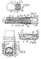
- Figure 1 is an exploded perspective view of the assembly but with no terminals mounted in the housings of the assembly;
- Figure 2 is a perspective view of part of one connector of the assembly in a dismantled state;
- Figure 3 is a perspective view of the connector part of Figure 2 in the assembled state;
- Figure 4 is a top plan view with part broken away, of the connector of Figures 2 and 3 in the assembled state;
- Figure 5 is a sectional view on the line V-V in Figure 6 through the assembly in the assembled state;
- Figure 6 is a section on the line VI-VI in Figure 5;
- Figure 7 is a view similar to Figure 5 but showing the assembly in a partly disassembled state;
- Figure 8 shows part of Figure 5 illustrating operation of a latching means of the assembly; and
- Figure 9 is a sectional view through one connector of the assembly, showing a cable clamping arrangement used therein.
- The assembly to be described is for connecting two multi-conductor cables, and incorporates connectors of the type disclosed in U.S. Patent Specification No. 3,760,335. For this reason, the connectors will be described only in sufficient detail for an understanding of the present invention, and in particular the terminals used in the connectors and the manner in which conductors are connected to the terminals will not be described herein.
- The assembly comprises first and second
matable connectors housing 3 or 4 of electrically insulating plastics material carrying a plurality of electrical terminals (not shown) matable with the terminals of the other connector. - The housing 3 has a
mating face 5 having a projectingskirt 6, while thehousing 4 has a mating face 7 on a projectingportion 8 shaped to be received in theskirt 6 of the housing 3, as clearly shown in Figures 5 and 7, when the connectors are mated. - The
portion 8 of thehousing 4 is formed with a longitudinally extending terminal-containingslot 9 which receives a terminal-separating wall 10 of the housing 3, all this as described in the above mentioned U.S. Patent Specification No. 3,760,335. - Opposite the
mating face 5 or 7 of eachhousing 3 or 4 is aconductor terminating face housing 3 or 4. - Each
housing 3 or 4 has a longitudinally extendingperipheral flange groove 15 or 16 in acover housing 3 or 4 to cover the connections between the terminals carried by thehousing 3 or 4 and conductors terminated thereto. The trailing end of eachcover cover housing 3 or 4, is formed with a dependingprojection resilient arm flange housing 3 or 4 is formed with arecess cover housing 3 or 4, receives theprojection cover housing 3 or 4. Thecover housing 3 or 4 by manual pressure on theprojection projection recess cover housing 3 or 4. - As clearly shown in Figures 1 and 9, the leading end of each
cover portion serrations portion plug corresponding serrations plug cover portion serrations plug cover plug wall cover portion cable engaging rib cover housing 3 or 4 with a cable 100 (Figure 9) having a plurality of conductors connected to terminals carried by thehousing 3 or 4, leaving thecover portion plug cover portion cable 100 becomes clamped between thewall plug rib cover - The connector assembly also includes a latching means operative to latch the
connectors metal spring member 37 having rounded inwardly directedprojections 38 at the free ends of itsarms 39. As clearly shown in Figures 5 and 6, thespring member 37 is engageable about the housing 3 of theconnector 1, with thearms 39 received inchannels 40 formed in the outer surfaces of the housing 3. Theprojections 38 at the ends of thearms 39 project through apertures 41 (see Figures 7 and 8) in the housing 3 to engage inrecesses 42 formed in thehousing 4 of theconnector 2 thereby to latch theconnectors - As shown in Figure 7, the
spring member 37 can be slid into its latching position after mating of theconnectors projections 38 passing along thechannels 40 until they enter theapertures 41 and engage in therecesses 42. However, as shown in Figure 1, the mating face of thehousing 4 is formed with two inwardly taperingguide slots 43 which communicate with therecesses 42 respectively, whereby with thespring member 37 mounted on the housing 3 with theprojections 38 received in theapertures 41, when thehousing 4 is mated with the housing 3, theprojections 38 of thespring member 37 engage in theguide slots 43 and are cammed outwardly to permit entry of the portion 7 of thehousing 4 into the housing 3. When thehousings 3 and 4 are fully mated theprojections 38 spring into therecesses 42 in thehousing 4 to latch the connectors together, as shown in Figures 5 and 6. - As clearly shown in Figure 5, when the
connectors spring member 37, thebight 44 of thespring member 37 is spaced from the adjacent wall of the housing 3. When it is required to unlatch the connectors thebight 44 is urged towards the housing 3, as indicated by an arrow A in Figure 8, this causing theprojections 38 to ride up the edges of theapertures 41 and thus be cammed out of therecesses 42 in thehousing 4 as indicated by an arrow B in Figure 8, thus permitting unmating of the connectors. As clearly shown in Figure 8 the edges of theapertures 41 are sloped to permit easy riding of theprojections 38 over the edges. When the connectors have been unmated thespring member 37 will return under its own resiliency to the rest position with theprojections 38 received in theapertures 41. - The connector assembly described above has the advantages that it can be assembled and disassembled without the use of special tools, that is purely manually, and that there are no loose parts such as the nuts and bolts used in known assemblies.
Claims (3)
1. An electrical connector assembly comprising first (1) and second (2) matable connectors each comprising a housing carrying a plurality of electrical terminals matable with the terminals of the other connector, the assembly including latching means to latch the connectors together in the mated condition, the latching means comprising a U-shaped spring member (37) having inwardly directed projections (38) at the free ends of the arms (38), the spring member being engageable about the housing (3) of the first connector with the projections engaging the housing (4) of the second connector thereby to latch the connectors together in the mated condition, characterised in that the housing (3) of the first connector (1) is formed with channels (40) which receive the arms (39) of the spring member (37), the channels (40) extending at right-angles to the direction of mating of the first and second connectors (1 and 2), the projections (38) of the spring member (37), in the mated condition of the first and second connectors (1 and 2), projecting through apertures (41) in the housing (3) of the first connector (1) and engaging in recesses (42) in the housing (4) of the second connector (2), the projections (38) and recesses (42) having cooperating planar surfaces extending at right-angles to the mating direction of the first and second connectors (1 and 2).
2. An assembly as claimed in Claim 1, characterised in that the housing (4) of the second connector (2) is formed with inwardly tapering guide slots (43) which communicate with the recesses (42) respectively, the guide slots (43) being adapted and arranged such that with the spring member (37) mounted on the housing (3) of the first connector (1) with the projections (38) received in the apertures (41) therein, when the housing (4) of the second connector (2) is mated with the housing (3) of the first connector (1), the projections (38) of the spring member (37) engage in the guide slots (43) and are cammed outwardly to permit mating of the connectors (1 and 2).
3. An assembly as claimed in Claim 1 or Claim 2, characterised in that in the latched mated condition, the bight (44) of the spring member (37) is spaced from the adjacent wall of the housing (3) of the first connector (1) whereby by urging the bight (44) towards the housing (3) of the first connector (1) the projections (38) of the spring member (37) are caused to ride up the edges of the apertures (41) in the housing (3) of the first connector (1) and thus be cammed out of the recesses (42) in the housing (4) of the second connector (2) to permit unmating of the connectors (1 and 2).
Applications Claiming Priority (2)
| Application Number | Priority Date | Filing Date | Title |
|---|---|---|---|
| US840349 | 1977-10-06 | ||
| US05/840,349US4130329A (en) | 1977-10-06 | 1977-10-06 | Electrical connector assembly retention system |
Publications (2)
| Publication Number | Publication Date |
|---|---|
| EP0001885A1 EP0001885A1 (en) | 1979-05-16 |
| EP0001885B1true EP0001885B1 (en) | 1982-04-07 |
Family
ID=25282119
Family Applications (1)
| Application Number | Title | Priority Date | Filing Date |
|---|---|---|---|
| EP78300430AExpiredEP0001885B1 (en) | 1977-10-06 | 1978-09-29 | Electrical connector assembly including latching means |
Country Status (7)
| Country | Link |
|---|---|
| US (1) | US4130329A (en) |
| EP (1) | EP0001885B1 (en) |
| JP (1) | JPS5463288A (en) |
| CA (1) | CA1107366A (en) |
| DE (1) | DE2861720D1 (en) |
| ES (1) | ES245503Y (en) |
| IT (1) | IT1099634B (en) |
Families Citing this family (16)
| Publication number | Priority date | Publication date | Assignee | Title |
|---|---|---|---|---|
| US4432592A (en)* | 1979-02-21 | 1984-02-21 | Allied Corporation | Electrical connector assembly |
| DE3150424C2 (en)* | 1981-06-16 | 1987-04-23 | Robert Bosch Gmbh, 7000 Stuttgart | Electrical connector |
| US4558914A (en)* | 1982-09-23 | 1985-12-17 | Gould Inc. | Readily expandable input/output construction for programmable controller |
| US4691979A (en)* | 1983-08-04 | 1987-09-08 | Manda R & D | Compliant press-fit electrical contact |
| US4538878A (en)* | 1983-08-12 | 1985-09-03 | Molex Incorporated | Solderless circuit board connector |
| US4653832A (en)* | 1984-02-29 | 1987-03-31 | Sanchez Michael A | Cable connector cover with integral strain relief |
| US4781330A (en)* | 1986-09-09 | 1988-11-01 | Custom Computer Cables, Inc. | Connector hood |
| NL8700210A (en)* | 1987-01-28 | 1988-08-16 | Du Pont Nederland | POWER CONNECTOR. |
| DE3738593A1 (en)* | 1987-11-13 | 1989-05-24 | Grote & Hartmann | MULTIPOLE ELECTRICAL CONNECTOR |
| US4842547A (en)* | 1988-05-19 | 1989-06-27 | Amp Incorporated | Staple cable strain relief |
| JPH03118432A (en)* | 1989-09-29 | 1991-05-21 | Terumo Corp | Electronic clinical thermometer and manufacture thereof |
| WO1996037924A1 (en)* | 1995-05-25 | 1996-11-28 | Futura Developments Limited | Electrical insulating device |
| EP0776068B1 (en)* | 1995-11-21 | 2001-06-06 | The Whitaker Corporation | Electrical connector assembly |
| DE19611965B4 (en)* | 1996-03-26 | 2006-09-07 | The Whitaker Corp., Wilmington | Arrangement for locking an electrical connector |
| DE19903416A1 (en)* | 1999-01-29 | 2000-08-24 | Harting Kgaa | Electrical plug connector e.g. for printed circuit boards, has spring element with front end pointing into inner chamber bounded by collar, and end of spring element acts upon wall surface of counter plug |
| US20060252308A1 (en)* | 2005-05-05 | 2006-11-09 | Siemens Westinghouse Power Corp. | Hazard boundary termination box |
Family Cites Families (12)
| Publication number | Priority date | Publication date | Assignee | Title |
|---|---|---|---|---|
| DE1465642A1 (en)* | 1963-11-11 | 1969-04-30 | Harting Elektro W | Electrical connector |
| US3398390A (en)* | 1966-07-18 | 1968-08-20 | Gen Electric | Spring lock electrical connector |
| US3566336A (en)* | 1968-08-30 | 1971-02-23 | Itt | Connector assembly |
| US3707696A (en)* | 1971-01-11 | 1972-12-26 | Amp Inc | Multi-contact electrical connector for flat cable |
| US3760335A (en)* | 1971-05-27 | 1973-09-18 | Amp Inc | Pre-loaded electric connector |
| DE2165037C3 (en)* | 1971-12-28 | 1975-04-30 | Siemens Ag, 1000 Berlin Und 8000 Muenchen | Lock for a multi-pole electrical connector |
| US3751579A (en)* | 1972-02-04 | 1973-08-07 | Honeywell Inc | Electrical wiring bushing with strain relief |
| US3904265A (en)* | 1972-02-23 | 1975-09-09 | Amp Inc | Electrical connector shield having an internal cable clamp |
| US3977748A (en)* | 1974-04-23 | 1976-08-31 | Molex Incorporated | Zero insertion force connector assembly |
| US3936129A (en)* | 1974-09-16 | 1976-02-03 | Western Electric Company, Inc. | Molded plastic hood assembly for a cable connector plug |
| JPS5442472Y2 (en)* | 1976-02-02 | 1979-12-10 | ||
| US4035051A (en)* | 1976-10-19 | 1977-07-12 | Western Electric Company, Inc. | Adjustable molded hood assembly for a cable connector plug |
- 1977
- 1977-10-06USUS05/840,349patent/US4130329A/ennot_activeExpired - Lifetime
- 1978
- 1978-09-28ITIT28211/78Apatent/IT1099634B/enactive
- 1978-09-29DEDE7878300430Tpatent/DE2861720D1/ennot_activeExpired
- 1978-09-29EPEP78300430Apatent/EP0001885B1/ennot_activeExpired
- 1978-10-05ESES1978245503Upatent/ES245503Y/ennot_activeExpired
- 1978-10-05CACA312,732Apatent/CA1107366A/ennot_activeExpired
- 1978-10-06JPJP12274678Apatent/JPS5463288A/enactiveGranted
Also Published As
| Publication number | Publication date |
|---|---|
| ES245503U (en) | 1980-01-01 |
| IT1099634B (en) | 1985-09-18 |
| ES245503Y (en) | 1980-06-16 |
| EP0001885A1 (en) | 1979-05-16 |
| US4130329A (en) | 1978-12-19 |
| IT7828211A0 (en) | 1978-09-28 |
| JPS6235228B2 (en) | 1987-07-31 |
| CA1107366A (en) | 1981-08-18 |
| JPS5463288A (en) | 1979-05-22 |
| DE2861720D1 (en) | 1982-05-19 |
Similar Documents
| Publication | Publication Date | Title |
|---|---|---|
| EP0561405B1 (en) | Hybrid input/output connector having low mating force and high cycle life and contacts and latching system therefor | |
| EP0001885B1 (en) | Electrical connector assembly including latching means | |
| US4341428A (en) | Interconnection system for shielded electrical cable | |
| EP0351083B1 (en) | Electrical connector | |
| US4941849A (en) | Shielded electrical connector having an insulating cover on the shielding member | |
| US5344335A (en) | Latching system for electrical connectors | |
| US4501459A (en) | Electrical connector | |
| US6231392B1 (en) | Cable interconnection | |
| US4653825A (en) | Shielded electrical connector assembly | |
| EP0592101B1 (en) | Electrical connector having improved strain relief | |
| US4786260A (en) | Electrical cable assembly | |
| JP3995174B2 (en) | Electrical connector | |
| USRE32760E (en) | Electrical connector | |
| US4455056A (en) | Multi-pin high voltage connector | |
| US4345813A (en) | Keyable connector-header assemblies for multiple conductor cables | |
| US5158481A (en) | Shielded electrical connector with torsioned shield interconnect | |
| EP0112711B1 (en) | Shunt-protected electrical connector | |
| US10886640B2 (en) | Conductive terminal and electrical connector | |
| EP0125786A2 (en) | Electrical connector assembly | |
| US4475786A (en) | T Bar cover latch | |
| US4444450A (en) | Flat transmission cable connector and housing therefor | |
| KR100198409B1 (en) | Self locking coupling terminal structure | |
| US4089579A (en) | Ribbon connector constructions | |
| US20090305536A1 (en) | Electrical connector having a lever assist mating mechanism | |
| EP0294460B1 (en) | Shielded data connector |
Legal Events
| Date | Code | Title | Description |
|---|---|---|---|
| PUAI | Public reference made under article 153(3) epc to a published international application that has entered the european phase | Free format text:ORIGINAL CODE: 0009012 | |
| AK | Designated contracting states | Designated state(s):DE FR GB | |
| 17P | Request for examination filed | ||
| GRAA | (expected) grant | Free format text:ORIGINAL CODE: 0009210 | |
| AK | Designated contracting states | Designated state(s):DE FR GB | |
| REF | Corresponds to: | Ref document number:2861720 Country of ref document:DE Date of ref document:19820519 | |
| REG | Reference to a national code | Ref country code:GB Ref legal event code:732E | |
| PGFP | Annual fee paid to national office [announced via postgrant information from national office to epo] | Ref country code:GB Payment date:19970804 Year of fee payment:20 | |
| PGFP | Annual fee paid to national office [announced via postgrant information from national office to epo] | Ref country code:FR Payment date:19970905 Year of fee payment:20 | |
| PGFP | Annual fee paid to national office [announced via postgrant information from national office to epo] | Ref country code:DE Payment date:19970930 Year of fee payment:20 | |
| PG25 | Lapsed in a contracting state [announced via postgrant information from national office to epo] | Ref country code:GB Free format text:LAPSE BECAUSE OF EXPIRATION OF PROTECTION Effective date:19980928 | |
| REG | Reference to a national code | Ref country code:GB Ref legal event code:PE20 Effective date:19980928 | |
| PLBE | No opposition filed within time limit | Free format text:ORIGINAL CODE: 0009261 | |
| STAA | Information on the status of an ep patent application or granted ep patent | Free format text:STATUS: NO OPPOSITION FILED WITHIN TIME LIMIT |